EP2965734B1 - Disposable underwear-style diaper - Google Patents
Disposable underwear-style diaper Download PDFInfo
- Publication number
- EP2965734B1 EP2965734B1 EP13877018.5A EP13877018A EP2965734B1 EP 2965734 B1 EP2965734 B1 EP 2965734B1 EP 13877018 A EP13877018 A EP 13877018A EP 2965734 B1 EP2965734 B1 EP 2965734B1
- Authority
- EP
- European Patent Office
- Prior art keywords
- leg
- region
- transverse direction
- edge
- elastic member
- Prior art date
- Legal status (The legal status is an assumption and is not a legal conclusion. Google has not performed a legal analysis and makes no representation as to the accuracy of the status listed.)
- Active
Links
Images


Classifications
-
- A—HUMAN NECESSITIES
- A61—MEDICAL OR VETERINARY SCIENCE; HYGIENE
- A61F—FILTERS IMPLANTABLE INTO BLOOD VESSELS; PROSTHESES; DEVICES PROVIDING PATENCY TO, OR PREVENTING COLLAPSING OF, TUBULAR STRUCTURES OF THE BODY, e.g. STENTS; ORTHOPAEDIC, NURSING OR CONTRACEPTIVE DEVICES; FOMENTATION; TREATMENT OR PROTECTION OF EYES OR EARS; BANDAGES, DRESSINGS OR ABSORBENT PADS; FIRST-AID KITS
- A61F13/00—Bandages or dressings; Absorbent pads
- A61F13/15—Absorbent pads, e.g. sanitary towels, swabs or tampons for external or internal application to the body; Supporting or fastening means therefor; Tampon applicators
- A61F13/45—Absorbent pads, e.g. sanitary towels, swabs or tampons for external or internal application to the body; Supporting or fastening means therefor; Tampon applicators characterised by the shape
- A61F13/49—Absorbent articles specially adapted to be worn around the waist, e.g. diapers
- A61F13/494—Absorbent articles specially adapted to be worn around the waist, e.g. diapers characterised by edge leakage prevention means
- A61F13/49406—Absorbent articles specially adapted to be worn around the waist, e.g. diapers characterised by edge leakage prevention means the edge leakage prevention means being at the crotch region
-
- A—HUMAN NECESSITIES
- A61—MEDICAL OR VETERINARY SCIENCE; HYGIENE
- A61F—FILTERS IMPLANTABLE INTO BLOOD VESSELS; PROSTHESES; DEVICES PROVIDING PATENCY TO, OR PREVENTING COLLAPSING OF, TUBULAR STRUCTURES OF THE BODY, e.g. STENTS; ORTHOPAEDIC, NURSING OR CONTRACEPTIVE DEVICES; FOMENTATION; TREATMENT OR PROTECTION OF EYES OR EARS; BANDAGES, DRESSINGS OR ABSORBENT PADS; FIRST-AID KITS
- A61F13/00—Bandages or dressings; Absorbent pads
- A61F13/15—Absorbent pads, e.g. sanitary towels, swabs or tampons for external or internal application to the body; Supporting or fastening means therefor; Tampon applicators
- A61F13/45—Absorbent pads, e.g. sanitary towels, swabs or tampons for external or internal application to the body; Supporting or fastening means therefor; Tampon applicators characterised by the shape
- A61F13/49—Absorbent articles specially adapted to be worn around the waist, e.g. diapers
- A61F13/49007—Form-fitting, self-adjusting disposable diapers
- A61F13/49009—Form-fitting, self-adjusting disposable diapers with elastic means
- A61F13/49017—Form-fitting, self-adjusting disposable diapers with elastic means the elastic means being located at the crotch region
-
- A—HUMAN NECESSITIES
- A61—MEDICAL OR VETERINARY SCIENCE; HYGIENE
- A61F—FILTERS IMPLANTABLE INTO BLOOD VESSELS; PROSTHESES; DEVICES PROVIDING PATENCY TO, OR PREVENTING COLLAPSING OF, TUBULAR STRUCTURES OF THE BODY, e.g. STENTS; ORTHOPAEDIC, NURSING OR CONTRACEPTIVE DEVICES; FOMENTATION; TREATMENT OR PROTECTION OF EYES OR EARS; BANDAGES, DRESSINGS OR ABSORBENT PADS; FIRST-AID KITS
- A61F13/00—Bandages or dressings; Absorbent pads
- A61F13/15—Absorbent pads, e.g. sanitary towels, swabs or tampons for external or internal application to the body; Supporting or fastening means therefor; Tampon applicators
- A61F13/45—Absorbent pads, e.g. sanitary towels, swabs or tampons for external or internal application to the body; Supporting or fastening means therefor; Tampon applicators characterised by the shape
- A61F13/49—Absorbent articles specially adapted to be worn around the waist, e.g. diapers
- A61F13/49007—Form-fitting, self-adjusting disposable diapers
- A61F13/49009—Form-fitting, self-adjusting disposable diapers with elastic means
- A61F13/49019—Form-fitting, self-adjusting disposable diapers with elastic means the elastic means being placed longitudinally, transversely or diagonally over the article
-
- A—HUMAN NECESSITIES
- A61—MEDICAL OR VETERINARY SCIENCE; HYGIENE
- A61F—FILTERS IMPLANTABLE INTO BLOOD VESSELS; PROSTHESES; DEVICES PROVIDING PATENCY TO, OR PREVENTING COLLAPSING OF, TUBULAR STRUCTURES OF THE BODY, e.g. STENTS; ORTHOPAEDIC, NURSING OR CONTRACEPTIVE DEVICES; FOMENTATION; TREATMENT OR PROTECTION OF EYES OR EARS; BANDAGES, DRESSINGS OR ABSORBENT PADS; FIRST-AID KITS
- A61F13/00—Bandages or dressings; Absorbent pads
- A61F13/15—Absorbent pads, e.g. sanitary towels, swabs or tampons for external or internal application to the body; Supporting or fastening means therefor; Tampon applicators
- A61F13/45—Absorbent pads, e.g. sanitary towels, swabs or tampons for external or internal application to the body; Supporting or fastening means therefor; Tampon applicators characterised by the shape
- A61F13/49—Absorbent articles specially adapted to be worn around the waist, e.g. diapers
- A61F13/49058—Absorbent articles specially adapted to be worn around the waist, e.g. diapers characterised by the modular concept of constructing the diaper
-
- A—HUMAN NECESSITIES
- A61—MEDICAL OR VETERINARY SCIENCE; HYGIENE
- A61F—FILTERS IMPLANTABLE INTO BLOOD VESSELS; PROSTHESES; DEVICES PROVIDING PATENCY TO, OR PREVENTING COLLAPSING OF, TUBULAR STRUCTURES OF THE BODY, e.g. STENTS; ORTHOPAEDIC, NURSING OR CONTRACEPTIVE DEVICES; FOMENTATION; TREATMENT OR PROTECTION OF EYES OR EARS; BANDAGES, DRESSINGS OR ABSORBENT PADS; FIRST-AID KITS
- A61F13/00—Bandages or dressings; Absorbent pads
- A61F13/15—Absorbent pads, e.g. sanitary towels, swabs or tampons for external or internal application to the body; Supporting or fastening means therefor; Tampon applicators
- A61F13/45—Absorbent pads, e.g. sanitary towels, swabs or tampons for external or internal application to the body; Supporting or fastening means therefor; Tampon applicators characterised by the shape
- A61F13/49—Absorbent articles specially adapted to be worn around the waist, e.g. diapers
- A61F13/494—Absorbent articles specially adapted to be worn around the waist, e.g. diapers characterised by edge leakage prevention means
- A61F13/49406—Absorbent articles specially adapted to be worn around the waist, e.g. diapers characterised by edge leakage prevention means the edge leakage prevention means being at the crotch region
- A61F13/49413—Absorbent articles specially adapted to be worn around the waist, e.g. diapers characterised by edge leakage prevention means the edge leakage prevention means being at the crotch region the edge leakage prevention means being an upstanding barrier
- A61F13/4942—Absorbent articles specially adapted to be worn around the waist, e.g. diapers characterised by edge leakage prevention means the edge leakage prevention means being at the crotch region the edge leakage prevention means being an upstanding barrier the barrier not being integral with the top- or back-sheet
-
- A—HUMAN NECESSITIES
- A61—MEDICAL OR VETERINARY SCIENCE; HYGIENE
- A61F—FILTERS IMPLANTABLE INTO BLOOD VESSELS; PROSTHESES; DEVICES PROVIDING PATENCY TO, OR PREVENTING COLLAPSING OF, TUBULAR STRUCTURES OF THE BODY, e.g. STENTS; ORTHOPAEDIC, NURSING OR CONTRACEPTIVE DEVICES; FOMENTATION; TREATMENT OR PROTECTION OF EYES OR EARS; BANDAGES, DRESSINGS OR ABSORBENT PADS; FIRST-AID KITS
- A61F13/00—Bandages or dressings; Absorbent pads
- A61F13/15—Absorbent pads, e.g. sanitary towels, swabs or tampons for external or internal application to the body; Supporting or fastening means therefor; Tampon applicators
- A61F13/45—Absorbent pads, e.g. sanitary towels, swabs or tampons for external or internal application to the body; Supporting or fastening means therefor; Tampon applicators characterised by the shape
- A61F13/49—Absorbent articles specially adapted to be worn around the waist, e.g. diapers
- A61F13/496—Absorbent articles specially adapted to be worn around the waist, e.g. diapers in the form of pants or briefs
-
- A—HUMAN NECESSITIES
- A61—MEDICAL OR VETERINARY SCIENCE; HYGIENE
- A61F—FILTERS IMPLANTABLE INTO BLOOD VESSELS; PROSTHESES; DEVICES PROVIDING PATENCY TO, OR PREVENTING COLLAPSING OF, TUBULAR STRUCTURES OF THE BODY, e.g. STENTS; ORTHOPAEDIC, NURSING OR CONTRACEPTIVE DEVICES; FOMENTATION; TREATMENT OR PROTECTION OF EYES OR EARS; BANDAGES, DRESSINGS OR ABSORBENT PADS; FIRST-AID KITS
- A61F13/00—Bandages or dressings; Absorbent pads
- A61F13/15—Absorbent pads, e.g. sanitary towels, swabs or tampons for external or internal application to the body; Supporting or fastening means therefor; Tampon applicators
- A61F13/45—Absorbent pads, e.g. sanitary towels, swabs or tampons for external or internal application to the body; Supporting or fastening means therefor; Tampon applicators characterised by the shape
- A61F13/49—Absorbent articles specially adapted to be worn around the waist, e.g. diapers
- A61F2013/49088—Absorbent articles specially adapted to be worn around the waist, e.g. diapers characterized by the leg opening
- A61F2013/49092—Absorbent articles specially adapted to be worn around the waist, e.g. diapers characterized by the leg opening comprising leg cuffs
-
- A—HUMAN NECESSITIES
- A61—MEDICAL OR VETERINARY SCIENCE; HYGIENE
- A61F—FILTERS IMPLANTABLE INTO BLOOD VESSELS; PROSTHESES; DEVICES PROVIDING PATENCY TO, OR PREVENTING COLLAPSING OF, TUBULAR STRUCTURES OF THE BODY, e.g. STENTS; ORTHOPAEDIC, NURSING OR CONTRACEPTIVE DEVICES; FOMENTATION; TREATMENT OR PROTECTION OF EYES OR EARS; BANDAGES, DRESSINGS OR ABSORBENT PADS; FIRST-AID KITS
- A61F13/00—Bandages or dressings; Absorbent pads
- A61F13/15—Absorbent pads, e.g. sanitary towels, swabs or tampons for external or internal application to the body; Supporting or fastening means therefor; Tampon applicators
- A61F13/45—Absorbent pads, e.g. sanitary towels, swabs or tampons for external or internal application to the body; Supporting or fastening means therefor; Tampon applicators characterised by the shape
- A61F13/49—Absorbent articles specially adapted to be worn around the waist, e.g. diapers
- A61F13/494—Absorbent articles specially adapted to be worn around the waist, e.g. diapers characterised by edge leakage prevention means
- A61F2013/4948—Absorbent articles specially adapted to be worn around the waist, e.g. diapers characterised by edge leakage prevention means the edge leakage prevention means being elastic
Definitions
- the present invention relates to disposable pull-on diapers, more in detail, the disposable pull-on diaper having a front panel defining a front waist region, a rear panel defining a rear waist region and a crotch panel defining a crotch region.
- JP 2008-508082 A discloses a disposable pull-on type wearing article of which an example is a disposable pull-on diaper and an example of this disposable pull-on diaper is a disposable pant-shaped diaper.
- Leg barrier cuffs rise toward the wearer's body as the diaper is put on the wearer's body.
- Patent Literature 2 An example of an absorbent article disclosed in JP H4-144558 A (Patent Literature 2) is a disposable pull-on diaper constituted by a longitudinally long main body including an absorbent body and an annular elastic belt. The main body is formed along both side edges with side flaps and, in leg side regions of these side flaps, gather forming elastic members are arranged.
- the leg barrier cuffs or the side flaps arranged on both side edge portions of the crotch panel may rise on the side edge portions of the absorbent body under contraction of the elastic members arranged in these barrier cuffs and side flaps so as to straiten the leg-openings. If the mother tries to pass the legs of her baby through the leg-openings straiten in this manner, there will be a possibility that the toe of the baby may be caught by the barrier cuffs or the side flaps, making it difficult to put the diaper on her baby smoothly and quickly.
- An object of the present invention is to provide a disposable pull-on diaper improved so that the diaper may be conveniently put on the wearer's body.
- the present invention is directed to a disposable pull-on diaper as recited by Claim 1.
- each of the leg side flaps in the crotch region is divided into the outer side region and the inner side region as viewed in the width direction and the respective regions are formed so that the respective regions may have a dimension of at least 10 mm, the inner side region may extend in the longitudinal direction and the outer side region may extend outward in the transverse direction.
- Fig. 1 is a perspective view of a diaper 10 for baby as an example of the disposable pull-on diaper according to the present invention and the diaper 10 is illustrated in a state subjected to no other external force than a force acting to broaden a waist-opening 22 described later.
- the diaper 10 has a front panel 12 defining a front waist region 2, a rear panel 13 defining a rear waist region 3 and a crotch panel 14 defining a crotch region 4.
- Side edge portions 16 opposed to each other in a transverse direction X of the front panel 12 and side edge portions 17 opposed to each other in the transverse direction X of the rear panel 13 are put flat and joined together along seams 15 made by ultrasonic joining.
- the crotch panel 14 has a front end portion 18 and a rear end portion 19, both described later, joined to an interior surface of the front panel 12 and an interior surface of the rear panel 13, respectively.
- the front panel 12 and the rear panel 13 cooperate with each other to form the waist-opening 22 and the front panel 12, the rear panel 13 and the crotch panel 14 cooperate together to form a pair of leg-openings 23.
- leg-openings 23 only one of leg-openings 23 is illustrated in Fig. 1 .
- Concerning each of the leg-openings 23, a lower portion of a peripheral region is defined by a leg side flap 42 in the crotch panel 14.
- the leg side flap 42 has an outer side region 91 and inner side region 92 as viewed in the transverse direction X of the diaper 10.
- double-headed arrows X, Y and Z indicate a transverse direction, a longitudinal direction and a front-back direction of the diaper 10.
- Fig. 2 is a partially cutaway plan view illustrating flatly extended diaper 10a obtained by unjoining the front and rear panels 12, 13 along the seals 15 and extending the front and rear panels 12, 13 and the crotch panel 14 in the transverse direction X and the front-back direction Z
- Fig. 3 is an exploded view of this extended diaper 10a.
- various elastic members described later are under tension in the transverse direction X or in the front-back direction Z.
- the extended diaper 10a has a longitudinal center line P bisecting a dimension in the transverse direction X and a transverse center line Q bisecting a dimension in the front-back direction Z wherein the extended diaper 10a is made symmetrically about the longitudinal center line P.
- extended used herein means that the diaper 10 is whereby or at least partially stretched in the transverse direction X, the longitudinal direction Y or in the front-back direction X until the gathers formed owing to contraction of the elastic members, or traces of folding disappear.
- the front panel 12 and the rear panel 13 cooperate with each other not only to form a waist region but also to function as an elastic belt to retain an absorbent structure 41 attached to the crotch panel 14 in a crotch region 4 of the wearer.
- the front panel 12 has an interior layer sheet 54 defining part of skin-facing surface corresponding to an interior surface of the diaper 10 and to an interior surface of the extended diaper also and an exterior layer sheet 56 defining an exterior surface, i.e., non-skin-facing surface of the extended diaper 10a.
- the exterior layer sheet 56 extends in the front-back direction Z in Fig. 2 from the interior layer sheet 54 and is folded back along an upper end edge 12a of the front panel 12 onto the side of an interior surface of the extended diaper 10a to overlap with this interior surface.
- first and second waist elastic members 57, 58 parallel extending in the transverse direction X are respectively secured under tension to the exterior layer sheet 56 with hot melt adhesive (not shown).
- the first waist elastic members 57 are interposed between the exterior layer sheet 56 folded back along the upper end edge 12a and overlapping with itself.
- the second waist elastic members 58 are interposed between an elongate cover sheet 59 partly forming the skin-facing surface and the exterior layer sheet 56.
- the rear panel 13 has an interior layer sheet 64 defining the skin-facing surface and an exterior layer sheet 66 defining the non-skin-facing surface.
- An upper-end portion the exterior layer sheet 66 extends in the front-back direction Z from the interior layer sheet 64 and is folded back along an upper end edge 13a of the rear panel 13 onto the interior surface to overlap therewith.
- a plurality of third and fourth waist elastic members 67, 68 extending parallel to the end edges 13a, 13b in the transverse direction X are arranged and secured to the outer layer sheet 66 with hot melt adhesive (not shown).
- the third waist elastics 67 are interposed between the exterior layer sheet 66 folded back along the upper end edge 13a and overlapping with itself.
- the fourth waist elastics 68 is interposed between a cover sheet 69 partly defining the skin-facing surface and the exterior layer sheet 66.
- nonwoven fabrics such as a spunbonded/meltblown/spunbonded nonwoven fabric (SMS nonwoven fabric) or a spunbonded nonwoven fabric each having a mass per unit area in a range of 15 to 30 g/m 2 or a plastic film having a thickness in a range of 10 to 50 ⁇ m may be used.
- SMS nonwoven fabric spunbonded/meltblown/spunbonded nonwoven fabric
- the second elastics 58 extend between the side edge portions 16 of the front panel 12 and the absorbent structure 41 on the crotch panel 14 so as to extend across the leg side flaps 42 but not to extend across the absorbent structure 41.
- the fourth waist elastics 68 extend between the side edge portions 17 of the rear panel 13 and the leg side flaps 42 not so as to extend across the absorbent structure 41 and the leg side flaps 42. Consequently, contraction of the fourth waist elastics 68 causes no contraction of the inner side regions 92 described later in more detail of the leg side flaps 42.
- the front panel 12 and the rear panel 13 illustrated in Fig. 1 and arranged as described above may elastically fit the wearer's waist under contraction of the first, second, third and fourth waist elastics 57, 58, 67, 68.
- the crotch panel 41 has the absorbent structure 41 located on a central region as viewed in the transverse direction X and the leg side flaps 42 extending in the front-back direction Z in Fig. 2 along the both side edges of the absorbent structure 41.
- the absorbent structure 41 has a front end portion 41a, a rear end portion 41b and an intermediate portion 41c.
- the front end portion 41a overlaps with the front panel 12 and is joined to the front panel 12 with hot melt adhesive (not shown) .
- the front end portion 41a is partly covered with the folded back exterior layer sheet 56.
- the rear end portion 41b overlaps with the rear panel 13 and is joined thereto through the intermediary of hot melt adhesive (not shown) and partly interposed between the exterior layer sheet 66 and the interior layer sheet 64 and joined to these two sheets 66, 64 with hot melt adhesive (not shown).
- Each of the leg side flaps 42 of the crotch panel 14 is dimensioned in the front-back direction Z to be smaller than that of the absorbent structure 41 and has a front end portion 42a joined to the cover sheet 59 in the front panel 12 with hot melt adhesive (not shown) and a rear end portion 42b joined to the cover sheet 69 in the rear panel 13 with hot melt adhesive (not shown).
- the absorbent structure 41 is constituted of an absorbent body 73 including an absorbent core 71 formed of, for example, fluff pulp or a mixture of fluff pulp and superabsorbent polymer particles widely used in the relevant technical field and a liquid-permeable covering sheet 72 formed of tissue paper or nonwoven fabrics, a liquid-permeable top sheet 74 adapted to cover at least upper surface, i.e., the skin-facing surface of the absorbent body 73 and a back sheet 76 formed of liquid-impermeable plastic films to cover a bottom surface of the absorbent body 73.
- An exterior sheet 79 (see Figs. 1 and 3 ) formed of nonwoven fabrics is joined on the outer surface of the back sheet 76 with hot melt adhesive (not shown) so that the exterior surface of the crotch panel 14 may have a fabric-like texture.
- Each of the leg side flaps 42 is formed from a pair of overlapping sheets 81, for example, a pair of water repellent nonwoven fabric sheets formed of thermoplastic synthetic fibers between which a plurality of thread-like leg elastics 82 are interposed, and has an outer side edge 83 and an inner side edge 84.
- the inner side edge 84 and a narrow region 86 extending along the inner side edge 84 and having a width dimension in a range of 2 to 5 mm are secured to the bottom surface of the absorbent body 73 and the back sheet 76 with hot melt adhesive (not sown) to define a proximal edge 87 of the leg side flap 42.
- the outer side edge 83 defines a distal edge 88 of the leg side flap 42.
- the leg side flap 42 has, as viewed in the transverse direction X, the outer side region 91 including a plurality of the leg elastic members 82 and the inner side region 92 including none of the leg elastic members 82.
- the leg elastic members 82 extend from the front end portion 42a to the rear end portion 42b of the leg side flap 42 under tension and in parallel and are joined to at least one of a pair of the overlapping sheets 81 with hot melt adhesive (not shown) .
- the outer side region 91 is elastically contractible in the front-back direction Z in Fig. 2 and, in the diaper 10 in the state as illustrated in Fig. 1 , a number of gathers 93 are formed in the outer side region 91 under contraction.
- the inner side region 92 may be constituted of a pair of the sheets 81
- nonwoven fabrics are used as material for the sheets 81 and liquid-impermeable plastic films 94
- a polyethylene film having a thickness in a range of 10 to 20 ⁇ m is interposed between these two nonwoven fabric sheets 81 to make the inner side region 92 liquid-impermeable.
- the plastic film 94 is present only in the inner side region 92 to avoid a possibility that, if the plastic film 94 is present also in the outer side region 94, elastic contraction required for the outer side region 91 may be restricted by the presence of the plastic film 94.
- Fig. 4 is a sectional view taken along line IV-IV in Fig. 2 and the line IV-IV is in coincidence with the transverse center line Q.
- the transverse center line Q is in coincidence also with a line extending in the transverse direction X along the lowest region 70 of the crotch region 4.
- the leg side flaps 42 prepared separately of the absorbent structure 41 are joined at the respective proximal edges 87 to the absorbent structure 41 with hot melt adhesive HA.
- the other regions of hot melt adhesive in Fig. 4 are not shown.
- a pair of sheets 81 defining each of the leg side flaps 42 are formed of a single nonwoven fabric sheet doubled up along the distal edge 88.
- the outer side region 91 of the leg side flap 42 includes the outermost elastic member 82a located along the distal edge 88 and designated as a first elastic member in the present invention and inner side elastic members 82b-82f arranged between the outermost elastic member 82a and the inner side region 92 and designated as the second elastic member or the third elastic members in the present invention.
- the designation "the second elastic members” used herein means the leg elastic members arranged on the inner side of the outermost elastic member 82a and having the same stretch ratio as that of the first elastic member 82a and the designation "the third elastic” used herein means the leg side elastic members arranged on the inner side of the outermost elastic member 82a and having a stretch ratio higher than that of the outermost elastic member 82a.
- the third elastic members are located in an inner side area in the outer side region 91.
- the inner side elastic member 82f of the inner side elastic members 82b-82f is designated as the innermost elastic member.
- Such outer side region 91 includes lateral sub-regions extending in the transverse direction X across the lowest region 70 of the crotch panel 14, i.e., the lateral sub-regions extending along the transverse center line Q which extends across the lowest region 70 and each of these lateral sub-regions has a dimension L 1 in the transverse direction X preset to at least 10 mm.
- the dimension L 1 is the dimension from the distal edge 88 to the innermost elastic member in the outer side region 91, for example, to the inner side elastic member 82f.
- the term "stretch ratio" used herein means a ratio S 1 /S 2 , specifically, a ratio of a length S 1 of the elastic member measured on a test piece prepared by cutting out from the leg side flap 42 so as to include one of the leg elastic at a moment that the sheet 81 has been pulled until the gather due to contraction of the elastic member disappears versus a length S 2 of the elastic member in natural but straightened state after having been detached from the test piece by immersing the test piece in toluene solution.
- the lengths S 1 , S 2 may be defined, respectively, by dimensions between the lines marked on the test piece or the elastic member, respectively.
- extension force means a force required to extend the test piece including single leg elastic member from the length thereof in relaxed natural condition twice the length.
- any one of Autograph AG-Xplus series or a like-quality tester may be used at a rate of extension (a rate of pulling) set to 100 m/min.
- the inner side region 92 in the waist side flap 42 is the region having none of the leg elastic members 82 or the region including the elastic member having a stretch ratio lower than that of the outermost elastic member 82a.
- the inner side region 92 having the lateral sub-region extending in the transverse direction X across the lowest region 70 of the crotch panel 14 in which a dimension L 2 in the transverse direction X set to at least 10 mm. This dimension L 2 corresponds to the dimension from the proximal edge 87 to the innermost elastic member 82f arranged in the innermost sub-region of the outer side region 91, as illustrated.
- spandex having fineness in a range of 310 to 620 dtex may be used at a stretch ratio preset to a range of 2.0 to 3.0 as the leg elastic members 82.
- the sheet material widely known in the related technique field such as SMS nonwoven fabrics or spunbonded nonwoven fabrics each having a mass per unit area in a range of 15 to 30 g/m 2 may be used.
- Fig. 1 exemplarily illustrates the case in which the inner side elastic members 82b-82f being the same as the outermost elastic member 82 in thickness as well as in length are used at the same stretch ratio as that of the outermost elastic member 82a.
- the inner side region 92 of the leg side flap 42 positively stands up so as to intersect with an imaginary vertical line Y 1 parallel to a vertical line indicated by a double-headed arrow Y at a relatively small intersecting angle ⁇ .
- the outer side region 91 in which the elastic members 82a-82f are in a contracted state extends in the transverse direction X so as to intersect with the vertical line Y 1 at a relatively large intersecting angle ⁇ .
- the inner side region 92 positively rises in the longitudinal direction Y and the outer side region 91 extends in the transverse direction X from the inner side region 92.
- the leg openings 23 formed in the above-mentioned manner according to this embodiment make it possible to maintain the leg openings in sufficiently opened condition.
- the leg openings 23 are visually recognizable and easily targetable through the waist opening for a mother intending to put the diaper 10 on her baby's body.
- operation of passing the baby's legs through the leg openings 23 is facilitated. This operation is facilitated not only for the reason that the leg openings are maintained in sufficiently opened condition but also for the other reason relating to the particular arrangement of the leg side flaps 42.
- each of the leg side flaps 42 includes the regions defining walls which may rise and catch the baby's toe when the mother intends to pass her baby's legs through the leg openings 23, such regions in question are only the inner side regions 92.
- the walls are sufficiently low to facilitate the mother's handling.
- the distal edges 88 and the vicinity thereof rather behave to extend outward in the transverse direction X than upward in the longitudinal direction Y and such behavior facilitates the distal edges 88 and the vicinity thereof to extend downward along the legs in the course of passing the legs through the leg openings 23. Consequently, the entirety of the outer side regions 91 as viewed in the transverse direction X extend downward and smoothly come in close contact around the respective legs at a desired fit.
- leg side flaps 42 as a whole extend upward, the leg side flaps 42 as a whole will remain in extending upward even after the diaper 10 has been put on the baby's body so as to intersect with the vertical line Y 1 at a relatively small intersecting angle and, as the case may be, an exterior surface of a portion of one or both leg side flaps 42 will come in contact around the baby's legs, causing a possibility that the bodily-fluids such as urine leak may occur around the baby's legs.
- the mother after having put the diaper 10 on the baby's body, it will be required for the mother to insert her hand(s) from the outside of the diaper 10 into the inside of the leg openings 23 and to force the portion in question to extend downward.
- the diaper 10 according to the present invention assures that the respective outer side regions 91 are kept in close contact around the baby's legs at a desired fit to prevent leakage of the bodily-fluids which may occur around the legs without any troublesome posterior handling required for the mother.
- the fourth elastic members 68 for the rear panel 13 extend so as to intersect with the leg elastic members 82 arranged in the outer side regions 91 of the leg side flaps 42 but extend not to the inner side regions 92.
- the dimension L 2 in the transverse direction X of the inner side regions 92 is not shortened even under contraction of the fourth waist elastic members 68 and the inner side regions 92 are apt to intersect with the vertical lines Y 1 indicated in Fig. 1 at a relatively large intersecting angle in the vicinity of the lowest region 70 of the crotch region 4.
- the vertical lines Y 1 in Fig. 1 is defined as will be described as follows: an imaginary line X1 connecting top portions 10a of the side edge portions 16, 17 respectively opposite in the transverse direction X along which the front and rear panels 12, 13 are joined to each other may be horizontalized to be put approximately in coincidence with a double-headed arrow mark X.
- the vertical line Y 1 in Fig. 1 is the vertical line being orthogonal to such horizontal imaginary line X1 or another vertical line being orthogonal to such vertical line.
- Fig. 5 is a side view of the diaper 10 in Fig. 1 , illustrating one of the leg openings 23 observed at a horizontal visual angle.
- the outer side region 91 of the leg side flap 42 functions to outspread the leg opening 23.
- Fig. 6 is a view similar to Fig. 4 , illustrating another embodiment.
- leakage barrier cuffs 101 extending in the front-back direction Z are formed along the side edges of the absorbent structure 41.
- Each of the leakage barrier cuffs 101 is widely known in the relevant technical field and includes a base edge portion 102 joined to the leg side flap 42 in the vicinity of the proximal edge 87 and extending in the front-back direction Z and a free edge portion 103 extending in the front-back direction Z in parallel to the base edge portion 102 and provided with an elastic member 104 attached thereto under tension.
- the free edge portion 103 rises on the absorbent structure 41 as indicated by an imaginary line under contraction of the elastic member 104 and functions as the leakage barrier cuff 101.
- the free edge portion 103 collapses onto the skin-facing surface of the absorbent structure 41 and bonded thereto.
- Such leakage barrier cuff 101 has a height H defined by a distance between the base edge portion 102 and the free edge portion 103 on the center line Q (see Fig.
- the base edge portion 102 of the leakage barrier cuff 101 may be attached so as to overlap the proximal edge 87 or attached contiguously to the proximal edge 87 to assure that, even when the free edge portion 103 rises as indicated by an imaginary line under contraction of the elastic member 104, there is no possibility that the inner side region 92 of the leg side flap 42 may move upward together with the free edge portion 103 and positively rise from the proximal edge 87. In this manner, when the mother intends to pass the baby's legs through the leg openings 23, the baby's toe or toes may not be caught by the inner side regions 92 owing the presence of the leakage barrier cuffs 101.
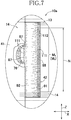
- Fig. 7 is a partially enlarged view of Fig. 2 to illustrate still another embodiment.
- a plurality of the proximal edge 87 of the leg side flap 42 formed with a number of gathers 111 parallel arranged in the transverse direction X, in other words, in the width direction of the leg side flap 42 is attached to the back sheet 76 and/or the exterior layer sheet 79 with hot melt adhesive (not shown) .
- the gathers 111 are formed also in a region between the proximal edge 87 and the distal edge 88.
- the outer side region 91 also is formed with gathers 112 under contraction of the leg elastic members 82.
- An apparent dimension M1 of such leg side flap 42 between the front panel 12 and the rear panel 13 is the same to a dimension N of the absorbent structure 41 as long as viewed in Fig. 7 .
- a real dimension M2 of the leg side flap 42 as measured on the leg side flap 42 extended until the gathers 111, 112 disappear is a real length of the sheet 81 extending between the front and rear panels 12, 13 in Fig. 7 and a length thereof is larger than the dimension N.
- leg side flap 42 formed in this manner, an elastic contraction of the outer side region 91 is not restricted or negligibly restricted by the absorbent structure 41, allowing the outer side region 91 to contract with no significant restriction.
- the outer side region 91 in which the leg elastic members 82, for example, the leg elastic members 82 exemplarily illustrated in Fig. 4 more specifically, all the elastic members 82a-82f are uniform to extend approximately in parallel to the imaginary line X1 or at a small angle of obliquity to the imaginary line X1.
- the leg openings 23 including such outer side regions 91 ensure sufficient sizes to make it easy to pass the baby's legs therethrough.
- leg side flaps 42 By the way, a method of attaching such leg side flaps 42 to the absorbent structure 41 will be exemplarily described hereunder. Feeding a first web as a continuum of the sheet 81 forming the leg side flaps 42 in a machine direction, continuous elastic members as a continuum of the leg elastic members stretched at a desired stretch ratio is fed in the machine direction and secured to the first web at desired regions thereof to form first composite web.
- a pair of a first feed rollers having a relatively high circumferential velocity is set upstream in the machine direction and a pair of second feed rollers having a relatively low circumferential velocity is set downstream in the machine direction so that the first composite web may be formed with gathers corresponding to the gathers 111 upstream of the second feed rollers as the first composite web passes through these first and second feed rollers.
- the first web formed with the gathers in this manner is joined to a web as a continuum of the back sheet 76 with hot melt adhesive to form second composite web immediately after having passed through the a second feed rollers.
- the second composite web is joined to predetermined regions of the absorbent body 73 or the top sheet 74 or the back sheet 76 covering the absorbent body 73 intermittently fed in the machine direction with hot melt adhesive.
- Fig. 8 is a photo exemplarily showing a condition of the outer side regions 91 and the inner side regions 92 of the leg side flaps 42 as observed from the front of the diaper 10.
- the front panel 12 has been extended together with the rear panel 13 until the gathers generated under contraction of the first and second waist elastic members 57, 58 disappear and the diaper 10 has been fixed to a flat plate (not shown) with the straightened upper end edge 12a of the front panel 12 being horizontalized.
- Fig. 8 may be designated also as a front elevational view of such diaper 10.
- the upper end edge 12a of this diaper 10 may be assumed as a horizontal line in coincidence with the imaginary line X1 in Fig. 1 .
- Fig. 8 indicates lines E, F passing the points A, B and orthogonal to the upper end edge 1a of the front panel 12.
- the lines E, F are parallel to each other and also to the vertical line Y 1 in Fig. 1 . With use of such photo, it is possible to compare degrees of inclination of the outer side region 91 and the inner side region 92 of the leg side flap 42 in a quantitative manner.
- the inventors measured the intersecting angle ⁇ between the first straight line AB passing through the points A, B and the line E and the intersecting angle ⁇ between the second straight line BC passing through the points B, C and the line E.
- the measurement result suggested that, at least in the diaper 10 for baby, the intersecting angle ⁇ in a range of 15 to 40° and the intersecting angle ⁇ in a range of 50 to 90° ensure that the diaper 10 is smoothly put on the baby's body and the possibility of bodily fluid leakage is effectively restricted.
Applications Claiming Priority (2)
| Application Number | Priority Date | Filing Date | Title |
|---|---|---|---|
| JP2013047393 | 2013-03-08 | ||
| PCT/JP2013/065630 WO2014136281A1 (ja) | 2013-03-08 | 2013-06-05 | 使い捨てのパンツ型おむつ |
Publications (3)
| Publication Number | Publication Date |
|---|---|
| EP2965734A1 EP2965734A1 (en) | 2016-01-13 |
| EP2965734A4 EP2965734A4 (en) | 2016-03-23 |
| EP2965734B1 true EP2965734B1 (en) | 2019-10-16 |
Family
ID=50112405
Family Applications (1)
| Application Number | Title | Priority Date | Filing Date |
|---|---|---|---|
| EP13877018.5A Active EP2965734B1 (en) | 2013-03-08 | 2013-06-05 | Disposable underwear-style diaper |
Country Status (13)
| Country | Link |
|---|---|
| US (1) | US10123915B2 (ru) |
| EP (1) | EP2965734B1 (ru) |
| JP (1) | JP5400982B1 (ru) |
| KR (1) | KR102181975B1 (ru) |
| CN (1) | CN105073080B (ru) |
| AU (1) | AU2013381272B2 (ru) |
| BR (1) | BR112015019465B1 (ru) |
| EA (1) | EA030105B1 (ru) |
| MY (1) | MY179751A (ru) |
| PH (1) | PH12015501692B1 (ru) |
| SA (1) | SA515360993B1 (ru) |
| SG (1) | SG11201506692YA (ru) |
| WO (1) | WO2014136281A1 (ru) |
Families Citing this family (4)
| Publication number | Priority date | Publication date | Assignee | Title |
|---|---|---|---|---|
| JP5960791B2 (ja) * | 2014-12-24 | 2016-08-02 | 花王株式会社 | パンツ型吸収性物品 |
| JP6224782B1 (ja) * | 2016-07-28 | 2017-11-01 | 花王株式会社 | パンツ型吸収性物品 |
| JP7473307B2 (ja) * | 2019-08-21 | 2024-04-23 | ユニ・チャーム株式会社 | パンツ型吸収性物品 |
| JP2023162995A (ja) * | 2022-04-27 | 2023-11-09 | 大王製紙株式会社 | パンツタイプ使い捨て着用物品 |
Family Cites Families (15)
| Publication number | Priority date | Publication date | Assignee | Title |
|---|---|---|---|---|
| JPS5184622A (ru) * | 1975-01-22 | 1976-07-24 | Sanyo Electric Co | |
| MA21077A1 (fr) * | 1986-10-10 | 1988-07-01 | Procter & Gamble | Article absorbant comportant des doubles manchettes resistant aux fluides . |
| JP3015091B2 (ja) | 1990-10-05 | 2000-02-28 | 花王株式会社 | 使い捨て吸収性物品及びその製造方法 |
| JPH04244152A (ja) * | 1991-01-30 | 1992-09-01 | Kao Corp | パンツ型おむつ |
| JP3209355B2 (ja) | 1992-01-17 | 2001-09-17 | 花王株式会社 | パンツ型使い捨ておむつ |
| US5911713A (en) * | 1994-08-23 | 1999-06-15 | Yamada; Jiro | Absorbent product with leg closures |
| US5993433A (en) * | 1997-10-20 | 1999-11-30 | Kimberly-Clark Worldwide, Inc. | Absorbent article with enhanced elastic design for improved aesthetics and containment |
| JP3398047B2 (ja) * | 1998-04-24 | 2003-04-21 | ユニ・チャーム株式会社 | 使い捨てのパンツ型おむつ |
| JP4330281B2 (ja) * | 2001-01-17 | 2009-09-16 | 花王株式会社 | パンツ型使い捨ておむつ |
| JP4244152B2 (ja) * | 2003-03-25 | 2009-03-25 | 三菱電機株式会社 | 換気用箱体 |
| MX2007001430A (es) | 2004-08-05 | 2008-10-27 | Procter & Gamble | Prenda desechable tipo calzon. |
| ES2532262T3 (es) * | 2004-12-06 | 2015-03-25 | Dsg Technology Holdings Ltd. | Artículo absorbente desechable que tiene envolturas para las piernas y método de fabricación del mismo |
| JP5479865B2 (ja) * | 2009-11-30 | 2014-04-23 | 花王株式会社 | パンツ型吸収性物品 |
| JP5346276B2 (ja) * | 2009-12-28 | 2013-11-20 | ユニ・チャーム株式会社 | 着用物品 |
| JP5135379B2 (ja) * | 2010-04-07 | 2013-02-06 | ユニ・チャーム株式会社 | 吸収性物品 |
-
2013
- 2013-06-05 JP JP2013119222A patent/JP5400982B1/ja active Active
- 2013-06-05 SG SG11201506692YA patent/SG11201506692YA/en unknown
- 2013-06-05 KR KR1020157023927A patent/KR102181975B1/ko active IP Right Grant
- 2013-06-05 MY MYPI2015702422A patent/MY179751A/en unknown
- 2013-06-05 US US14/772,776 patent/US10123915B2/en active Active
- 2013-06-05 CN CN201380073799.0A patent/CN105073080B/zh active Active
- 2013-06-05 EP EP13877018.5A patent/EP2965734B1/en active Active
- 2013-06-05 BR BR112015019465-6A patent/BR112015019465B1/pt active IP Right Grant
- 2013-06-05 AU AU2013381272A patent/AU2013381272B2/en not_active Ceased
- 2013-06-05 WO PCT/JP2013/065630 patent/WO2014136281A1/ja active Application Filing
- 2013-06-05 EA EA201591208A patent/EA030105B1/ru not_active IP Right Cessation
-
2015
- 2015-07-31 PH PH12015501692A patent/PH12015501692B1/en unknown
- 2015-09-06 SA SA515360993A patent/SA515360993B1/ar unknown
Non-Patent Citations (1)
| Title |
|---|
| None * |
Also Published As
| Publication number | Publication date |
|---|---|
| JP5400982B1 (ja) | 2014-01-29 |
| CN105073080B (zh) | 2019-05-17 |
| US20160015575A1 (en) | 2016-01-21 |
| SG11201506692YA (en) | 2015-09-29 |
| US10123915B2 (en) | 2018-11-13 |
| AU2013381272A1 (en) | 2015-08-27 |
| PH12015501692A1 (en) | 2015-12-07 |
| EA030105B1 (ru) | 2018-06-29 |
| CN105073080A (zh) | 2015-11-18 |
| JP2014195631A (ja) | 2014-10-16 |
| EP2965734A1 (en) | 2016-01-13 |
| PH12015501692B1 (en) | 2015-12-07 |
| MY179751A (en) | 2020-11-12 |
| KR102181975B1 (ko) | 2020-11-24 |
| AU2013381272B2 (en) | 2018-07-19 |
| SA515360993B1 (ar) | 2017-01-29 |
| BR112015019465A2 (pt) | 2017-07-18 |
| EP2965734A4 (en) | 2016-03-23 |
| BR112015019465B1 (pt) | 2021-01-26 |
| KR20150128685A (ko) | 2015-11-18 |
| EA201591208A1 (ru) | 2016-05-31 |
| WO2014136281A1 (ja) | 2014-09-12 |
Similar Documents
| Publication | Publication Date | Title |
|---|---|---|
| JP6153338B2 (ja) | 低月齢児用パンツ型おむつ | |
| AU2015235782B2 (en) | Absorbent article | |
| EP2554149B1 (en) | Disposable article for wearing | |
| EP2832327B1 (en) | Disposable undergarment | |
| EP2805700A1 (en) | Disposable worn article | |
| JP5996511B2 (ja) | パンツ型の着用物品 | |
| EP2965734B1 (en) | Disposable underwear-style diaper | |
| JP5592578B1 (ja) | パンツ型の着用物品 | |
| CN105705123B (zh) | 内裤型的一次性吸收性物品 | |
| US10016317B2 (en) | Pull-on disposable wearing article | |
| KR101759815B1 (ko) | 팬츠형 기저귀 | |
| JP5871506B2 (ja) | 使い捨て着用物品 | |
| TW201630581A (zh) | 用後即棄式穿著用物品 | |
| KR20140092927A (ko) | 일회용 기저귀 | |
| KR20160037886A (ko) | 일회용 기저귀 | |
| WO2014203679A1 (ja) | プルオンおむつ | |
| BR112016010066B1 (pt) | Artigo do vestuário tipo calça | |
| KR20160037885A (ko) | 일회용 기저귀 |
Legal Events
| Date | Code | Title | Description |
|---|---|---|---|
| PUAI | Public reference made under article 153(3) epc to a published international application that has entered the european phase |
Free format text: ORIGINAL CODE: 0009012 |
|
| 17P | Request for examination filed |
Effective date: 20150820 |
|
| AK | Designated contracting states |
Kind code of ref document: A1 Designated state(s): AL AT BE BG CH CY CZ DE DK EE ES FI FR GB GR HR HU IE IS IT LI LT LU LV MC MK MT NL NO PL PT RO RS SE SI SK SM TR |
|
| AX | Request for extension of the european patent |
Extension state: BA ME |
|
| A4 | Supplementary search report drawn up and despatched |
Effective date: 20160223 |
|
| RIC1 | Information provided on ipc code assigned before grant |
Ipc: A61F 13/494 20060101ALI20160217BHEP Ipc: A61F 13/496 20060101AFI20160217BHEP Ipc: A61F 13/49 20060101ALI20160217BHEP Ipc: A61F 13/15 20060101ALI20160217BHEP |
|
| DAX | Request for extension of the european patent (deleted) | ||
| STAA | Information on the status of an ep patent application or granted ep patent |
Free format text: STATUS: EXAMINATION IS IN PROGRESS |
|
| 17Q | First examination report despatched |
Effective date: 20170704 |
|
| GRAP | Despatch of communication of intention to grant a patent |
Free format text: ORIGINAL CODE: EPIDOSNIGR1 |
|
| STAA | Information on the status of an ep patent application or granted ep patent |
Free format text: STATUS: GRANT OF PATENT IS INTENDED |
|
| INTG | Intention to grant announced |
Effective date: 20190513 |
|
| GRAS | Grant fee paid |
Free format text: ORIGINAL CODE: EPIDOSNIGR3 |
|
| GRAA | (expected) grant |
Free format text: ORIGINAL CODE: 0009210 |
|
| STAA | Information on the status of an ep patent application or granted ep patent |
Free format text: STATUS: THE PATENT HAS BEEN GRANTED |
|
| AK | Designated contracting states |
Kind code of ref document: B1 Designated state(s): AL AT BE BG CH CY CZ DE DK EE ES FI FR GB GR HR HU IE IS IT LI LT LU LV MC MK MT NL NO PL PT RO RS SE SI SK SM TR |
|
| REG | Reference to a national code |
Ref country code: GB Ref legal event code: FG4D |
|
| REG | Reference to a national code |
Ref country code: CH Ref legal event code: EP |
|
| REG | Reference to a national code |
Ref country code: DE Ref legal event code: R096 Ref document number: 602013061872 Country of ref document: DE |
|
| REG | Reference to a national code |
Ref country code: IE Ref legal event code: FG4D |
|
| REG | Reference to a national code |
Ref country code: AT Ref legal event code: REF Ref document number: 1190577 Country of ref document: AT Kind code of ref document: T Effective date: 20191115 |
|
| REG | Reference to a national code |
Ref country code: SE Ref legal event code: TRGR |
|
| REG | Reference to a national code |
Ref country code: NL Ref legal event code: FP |
|
| REG | Reference to a national code |
Ref country code: LT Ref legal event code: MG4D |
|
| REG | Reference to a national code |
Ref country code: AT Ref legal event code: MK05 Ref document number: 1190577 Country of ref document: AT Kind code of ref document: T Effective date: 20191016 |
|
| PG25 | Lapsed in a contracting state [announced via postgrant information from national office to epo] |
Ref country code: PT Free format text: LAPSE BECAUSE OF FAILURE TO SUBMIT A TRANSLATION OF THE DESCRIPTION OR TO PAY THE FEE WITHIN THE PRESCRIBED TIME-LIMIT Effective date: 20200217 Ref country code: FI Free format text: LAPSE BECAUSE OF FAILURE TO SUBMIT A TRANSLATION OF THE DESCRIPTION OR TO PAY THE FEE WITHIN THE PRESCRIBED TIME-LIMIT Effective date: 20191016 Ref country code: BG Free format text: LAPSE BECAUSE OF FAILURE TO SUBMIT A TRANSLATION OF THE DESCRIPTION OR TO PAY THE FEE WITHIN THE PRESCRIBED TIME-LIMIT Effective date: 20200116 Ref country code: AT Free format text: LAPSE BECAUSE OF FAILURE TO SUBMIT A TRANSLATION OF THE DESCRIPTION OR TO PAY THE FEE WITHIN THE PRESCRIBED TIME-LIMIT Effective date: 20191016 Ref country code: LV Free format text: LAPSE BECAUSE OF FAILURE TO SUBMIT A TRANSLATION OF THE DESCRIPTION OR TO PAY THE FEE WITHIN THE PRESCRIBED TIME-LIMIT Effective date: 20191016 Ref country code: ES Free format text: LAPSE BECAUSE OF FAILURE TO SUBMIT A TRANSLATION OF THE DESCRIPTION OR TO PAY THE FEE WITHIN THE PRESCRIBED TIME-LIMIT Effective date: 20191016 Ref country code: NO Free format text: LAPSE BECAUSE OF FAILURE TO SUBMIT A TRANSLATION OF THE DESCRIPTION OR TO PAY THE FEE WITHIN THE PRESCRIBED TIME-LIMIT Effective date: 20200116 Ref country code: GR Free format text: LAPSE BECAUSE OF FAILURE TO SUBMIT A TRANSLATION OF THE DESCRIPTION OR TO PAY THE FEE WITHIN THE PRESCRIBED TIME-LIMIT Effective date: 20200117 Ref country code: LT Free format text: LAPSE BECAUSE OF FAILURE TO SUBMIT A TRANSLATION OF THE DESCRIPTION OR TO PAY THE FEE WITHIN THE PRESCRIBED TIME-LIMIT Effective date: 20191016 Ref country code: PL Free format text: LAPSE BECAUSE OF FAILURE TO SUBMIT A TRANSLATION OF THE DESCRIPTION OR TO PAY THE FEE WITHIN THE PRESCRIBED TIME-LIMIT Effective date: 20191016 |
|
| PG25 | Lapsed in a contracting state [announced via postgrant information from national office to epo] |
Ref country code: HR Free format text: LAPSE BECAUSE OF FAILURE TO SUBMIT A TRANSLATION OF THE DESCRIPTION OR TO PAY THE FEE WITHIN THE PRESCRIBED TIME-LIMIT Effective date: 20191016 Ref country code: RS Free format text: LAPSE BECAUSE OF FAILURE TO SUBMIT A TRANSLATION OF THE DESCRIPTION OR TO PAY THE FEE WITHIN THE PRESCRIBED TIME-LIMIT Effective date: 20191016 Ref country code: IS Free format text: LAPSE BECAUSE OF FAILURE TO SUBMIT A TRANSLATION OF THE DESCRIPTION OR TO PAY THE FEE WITHIN THE PRESCRIBED TIME-LIMIT Effective date: 20200224 |
|
| PG25 | Lapsed in a contracting state [announced via postgrant information from national office to epo] |
Ref country code: AL Free format text: LAPSE BECAUSE OF FAILURE TO SUBMIT A TRANSLATION OF THE DESCRIPTION OR TO PAY THE FEE WITHIN THE PRESCRIBED TIME-LIMIT Effective date: 20191016 |
|
| REG | Reference to a national code |
Ref country code: DE Ref legal event code: R097 Ref document number: 602013061872 Country of ref document: DE |
|
| PG2D | Information on lapse in contracting state deleted |
Ref country code: IS |
|
| PG25 | Lapsed in a contracting state [announced via postgrant information from national office to epo] |
Ref country code: DK Free format text: LAPSE BECAUSE OF FAILURE TO SUBMIT A TRANSLATION OF THE DESCRIPTION OR TO PAY THE FEE WITHIN THE PRESCRIBED TIME-LIMIT Effective date: 20191016 Ref country code: EE Free format text: LAPSE BECAUSE OF FAILURE TO SUBMIT A TRANSLATION OF THE DESCRIPTION OR TO PAY THE FEE WITHIN THE PRESCRIBED TIME-LIMIT Effective date: 20191016 Ref country code: CZ Free format text: LAPSE BECAUSE OF FAILURE TO SUBMIT A TRANSLATION OF THE DESCRIPTION OR TO PAY THE FEE WITHIN THE PRESCRIBED TIME-LIMIT Effective date: 20191016 Ref country code: RO Free format text: LAPSE BECAUSE OF FAILURE TO SUBMIT A TRANSLATION OF THE DESCRIPTION OR TO PAY THE FEE WITHIN THE PRESCRIBED TIME-LIMIT Effective date: 20191016 Ref country code: IS Free format text: LAPSE BECAUSE OF FAILURE TO SUBMIT A TRANSLATION OF THE DESCRIPTION OR TO PAY THE FEE WITHIN THE PRESCRIBED TIME-LIMIT Effective date: 20200216 |
|
| PLBE | No opposition filed within time limit |
Free format text: ORIGINAL CODE: 0009261 |
|
| STAA | Information on the status of an ep patent application or granted ep patent |
Free format text: STATUS: NO OPPOSITION FILED WITHIN TIME LIMIT |
|
| PG25 | Lapsed in a contracting state [announced via postgrant information from national office to epo] |
Ref country code: IT Free format text: LAPSE BECAUSE OF FAILURE TO SUBMIT A TRANSLATION OF THE DESCRIPTION OR TO PAY THE FEE WITHIN THE PRESCRIBED TIME-LIMIT Effective date: 20191016 Ref country code: SK Free format text: LAPSE BECAUSE OF FAILURE TO SUBMIT A TRANSLATION OF THE DESCRIPTION OR TO PAY THE FEE WITHIN THE PRESCRIBED TIME-LIMIT Effective date: 20191016 Ref country code: SM Free format text: LAPSE BECAUSE OF FAILURE TO SUBMIT A TRANSLATION OF THE DESCRIPTION OR TO PAY THE FEE WITHIN THE PRESCRIBED TIME-LIMIT Effective date: 20191016 |
|
| 26N | No opposition filed |
Effective date: 20200717 |
|
| PG25 | Lapsed in a contracting state [announced via postgrant information from national office to epo] |
Ref country code: SI Free format text: LAPSE BECAUSE OF FAILURE TO SUBMIT A TRANSLATION OF THE DESCRIPTION OR TO PAY THE FEE WITHIN THE PRESCRIBED TIME-LIMIT Effective date: 20191016 |
|
| PG25 | Lapsed in a contracting state [announced via postgrant information from national office to epo] |
Ref country code: MC Free format text: LAPSE BECAUSE OF FAILURE TO SUBMIT A TRANSLATION OF THE DESCRIPTION OR TO PAY THE FEE WITHIN THE PRESCRIBED TIME-LIMIT Effective date: 20191016 |
|
| REG | Reference to a national code |
Ref country code: CH Ref legal event code: PL |
|
| PG25 | Lapsed in a contracting state [announced via postgrant information from national office to epo] |
Ref country code: LU Free format text: LAPSE BECAUSE OF NON-PAYMENT OF DUE FEES Effective date: 20200605 |
|
| REG | Reference to a national code |
Ref country code: BE Ref legal event code: MM Effective date: 20200630 |
|
| PG25 | Lapsed in a contracting state [announced via postgrant information from national office to epo] |
Ref country code: CH Free format text: LAPSE BECAUSE OF NON-PAYMENT OF DUE FEES Effective date: 20200630 Ref country code: IE Free format text: LAPSE BECAUSE OF NON-PAYMENT OF DUE FEES Effective date: 20200605 Ref country code: LI Free format text: LAPSE BECAUSE OF NON-PAYMENT OF DUE FEES Effective date: 20200630 |
|
| PG25 | Lapsed in a contracting state [announced via postgrant information from national office to epo] |
Ref country code: BE Free format text: LAPSE BECAUSE OF NON-PAYMENT OF DUE FEES Effective date: 20200630 |
|
| PG25 | Lapsed in a contracting state [announced via postgrant information from national office to epo] |
Ref country code: TR Free format text: LAPSE BECAUSE OF FAILURE TO SUBMIT A TRANSLATION OF THE DESCRIPTION OR TO PAY THE FEE WITHIN THE PRESCRIBED TIME-LIMIT Effective date: 20191016 Ref country code: MT Free format text: LAPSE BECAUSE OF FAILURE TO SUBMIT A TRANSLATION OF THE DESCRIPTION OR TO PAY THE FEE WITHIN THE PRESCRIBED TIME-LIMIT Effective date: 20191016 Ref country code: CY Free format text: LAPSE BECAUSE OF FAILURE TO SUBMIT A TRANSLATION OF THE DESCRIPTION OR TO PAY THE FEE WITHIN THE PRESCRIBED TIME-LIMIT Effective date: 20191016 |
|
| PG25 | Lapsed in a contracting state [announced via postgrant information from national office to epo] |
Ref country code: MK Free format text: LAPSE BECAUSE OF FAILURE TO SUBMIT A TRANSLATION OF THE DESCRIPTION OR TO PAY THE FEE WITHIN THE PRESCRIBED TIME-LIMIT Effective date: 20191016 |
|
| PGFP | Annual fee paid to national office [announced via postgrant information from national office to epo] |
Ref country code: NL Payment date: 20230515 Year of fee payment: 11 Ref country code: FR Payment date: 20230510 Year of fee payment: 11 Ref country code: DE Payment date: 20230502 Year of fee payment: 11 |
|
| PGFP | Annual fee paid to national office [announced via postgrant information from national office to epo] |
Ref country code: SE Payment date: 20230510 Year of fee payment: 11 |
|
| PGFP | Annual fee paid to national office [announced via postgrant information from national office to epo] |
Ref country code: GB Payment date: 20230427 Year of fee payment: 11 |