EP2965729A1 - Providing information to a user through somatosensory feedback - Google Patents
Providing information to a user through somatosensory feedback Download PDFInfo
- Publication number
- EP2965729A1 EP2965729A1 EP14181812.0A EP14181812A EP2965729A1 EP 2965729 A1 EP2965729 A1 EP 2965729A1 EP 14181812 A EP14181812 A EP 14181812A EP 2965729 A1 EP2965729 A1 EP 2965729A1
- Authority
- EP
- European Patent Office
- Prior art keywords
- data
- samples
- tactile interface
- interface devices
- array
- Prior art date
- Legal status (The legal status is an assumption and is not a legal conclusion. Google has not performed a legal analysis and makes no representation as to the accuracy of the status listed.)
- Granted
Links
- 230000003238 somatosensory effect Effects 0.000 title 1
- 238000013507 mapping Methods 0.000 claims abstract description 50
- 238000012545 processing Methods 0.000 claims description 58
- 238000000034 method Methods 0.000 claims description 49
- 230000005236 sound signal Effects 0.000 claims description 17
- 230000001131 transforming effect Effects 0.000 claims description 17
- 230000003595 spectral effect Effects 0.000 claims description 7
- 238000004590 computer program Methods 0.000 claims description 4
- 230000004044 response Effects 0.000 claims description 4
- 230000001953 sensory effect Effects 0.000 abstract description 22
- 238000006467 substitution reaction Methods 0.000 abstract description 20
- 206010011878 Deafness Diseases 0.000 abstract description 13
- 230000008447 perception Effects 0.000 abstract description 6
- 230000009466 transformation Effects 0.000 description 23
- 230000006835 compression Effects 0.000 description 14
- 238000007906 compression Methods 0.000 description 14
- 230000006870 function Effects 0.000 description 14
- 238000012546 transfer Methods 0.000 description 13
- 230000008569 process Effects 0.000 description 12
- 239000011159 matrix material Substances 0.000 description 10
- 238000000354 decomposition reaction Methods 0.000 description 9
- 230000009467 reduction Effects 0.000 description 7
- 230000008901 benefit Effects 0.000 description 6
- 238000010586 diagram Methods 0.000 description 6
- 238000001914 filtration Methods 0.000 description 6
- 238000013528 artificial neural network Methods 0.000 description 5
- 238000004891 communication Methods 0.000 description 5
- 238000007781 pre-processing Methods 0.000 description 5
- 238000013139 quantization Methods 0.000 description 5
- 230000035807 sensation Effects 0.000 description 5
- 238000012549 training Methods 0.000 description 5
- 230000000638 stimulation Effects 0.000 description 4
- 230000002123 temporal effect Effects 0.000 description 4
- 238000012935 Averaging Methods 0.000 description 3
- 230000003213 activating effect Effects 0.000 description 3
- 210000004556 brain Anatomy 0.000 description 3
- 239000007943 implant Substances 0.000 description 3
- 238000003064 k means clustering Methods 0.000 description 3
- 238000004519 manufacturing process Methods 0.000 description 3
- 239000000203 mixture Substances 0.000 description 3
- 230000003287 optical effect Effects 0.000 description 3
- 238000002513 implantation Methods 0.000 description 2
- 238000005070 sampling Methods 0.000 description 2
- 238000001228 spectrum Methods 0.000 description 2
- 230000003068 static effect Effects 0.000 description 2
- 238000001356 surgical procedure Methods 0.000 description 2
- 238000010408 sweeping Methods 0.000 description 2
- 230000001360 synchronised effect Effects 0.000 description 2
- 239000003826 tablet Substances 0.000 description 2
- WQZGKKKJIJFFOK-GASJEMHNSA-N Glucose Natural products OC[C@H]1OC(O)[C@H](O)[C@@H](O)[C@@H]1O WQZGKKKJIJFFOK-GASJEMHNSA-N 0.000 description 1
- 230000009471 action Effects 0.000 description 1
- 230000004913 activation Effects 0.000 description 1
- 230000004075 alteration Effects 0.000 description 1
- 238000013459 approach Methods 0.000 description 1
- 230000005540 biological transmission Effects 0.000 description 1
- 230000003139 buffering effect Effects 0.000 description 1
- 230000001413 cellular effect Effects 0.000 description 1
- 230000008859 change Effects 0.000 description 1
- 238000006243 chemical reaction Methods 0.000 description 1
- 238000010276 construction Methods 0.000 description 1
- 238000013500 data storage Methods 0.000 description 1
- 231100000895 deafness Toxicity 0.000 description 1
- 238000001514 detection method Methods 0.000 description 1
- 239000008103 glucose Substances 0.000 description 1
- 230000036541 health Effects 0.000 description 1
- 208000016354 hearing loss disease Diseases 0.000 description 1
- 230000010354 integration Effects 0.000 description 1
- 230000003993 interaction Effects 0.000 description 1
- 230000008520 organization Effects 0.000 description 1
- 210000001428 peripheral nervous system Anatomy 0.000 description 1
- 230000001105 regulatory effect Effects 0.000 description 1
- 230000021317 sensory perception Effects 0.000 description 1
- 230000031893 sensory processing Effects 0.000 description 1
- 239000007787 solid Substances 0.000 description 1
- 230000001225 therapeutic effect Effects 0.000 description 1
- 238000000844 transformation Methods 0.000 description 1
- 230000000007 visual effect Effects 0.000 description 1
Images


Classifications
-
- G—PHYSICS
- G09—EDUCATION; CRYPTOGRAPHY; DISPLAY; ADVERTISING; SEALS
- G09B—EDUCATIONAL OR DEMONSTRATION APPLIANCES; APPLIANCES FOR TEACHING, OR COMMUNICATING WITH, THE BLIND, DEAF OR MUTE; MODELS; PLANETARIA; GLOBES; MAPS; DIAGRAMS
- G09B21/00—Teaching, or communicating with, the blind, deaf or mute
- G09B21/009—Teaching or communicating with deaf persons
-
- A—HUMAN NECESSITIES
- A61—MEDICAL OR VETERINARY SCIENCE; HYGIENE
- A61F—FILTERS IMPLANTABLE INTO BLOOD VESSELS; PROSTHESES; DEVICES PROVIDING PATENCY TO, OR PREVENTING COLLAPSING OF, TUBULAR STRUCTURES OF THE BODY, e.g. STENTS; ORTHOPAEDIC, NURSING OR CONTRACEPTIVE DEVICES; FOMENTATION; TREATMENT OR PROTECTION OF EYES OR EARS; BANDAGES, DRESSINGS OR ABSORBENT PADS; FIRST-AID KITS
- A61F11/00—Methods or devices for treatment of the ears or hearing sense; Non-electric hearing aids; Methods or devices for enabling ear patients to achieve auditory perception through physiological senses other than hearing sense; Protective devices for the ears, carried on the body or in the hand
- A61F11/04—Methods or devices for enabling ear patients to achieve auditory perception through physiological senses other than hearing sense, e.g. through the touch sense
- A61F11/045—Methods or devices for enabling ear patients to achieve auditory perception through physiological senses other than hearing sense, e.g. through the touch sense using mechanical stimulation of nerves
-
- G—PHYSICS
- G06—COMPUTING; CALCULATING OR COUNTING
- G06F—ELECTRIC DIGITAL DATA PROCESSING
- G06F3/00—Input arrangements for transferring data to be processed into a form capable of being handled by the computer; Output arrangements for transferring data from processing unit to output unit, e.g. interface arrangements
- G06F3/01—Input arrangements or combined input and output arrangements for interaction between user and computer
- G06F3/016—Input arrangements with force or tactile feedback as computer generated output to the user
-
- G—PHYSICS
- G08—SIGNALLING
- G08B—SIGNALLING OR CALLING SYSTEMS; ORDER TELEGRAPHS; ALARM SYSTEMS
- G08B6/00—Tactile signalling systems, e.g. personal calling systems
-
- G—PHYSICS
- G09—EDUCATION; CRYPTOGRAPHY; DISPLAY; ADVERTISING; SEALS
- G09B—EDUCATIONAL OR DEMONSTRATION APPLIANCES; APPLIANCES FOR TEACHING, OR COMMUNICATING WITH, THE BLIND, DEAF OR MUTE; MODELS; PLANETARIA; GLOBES; MAPS; DIAGRAMS
- G09B21/00—Teaching, or communicating with, the blind, deaf or mute
- G09B21/001—Teaching or communicating with blind persons
- G09B21/003—Teaching or communicating with blind persons using tactile presentation of the information, e.g. Braille displays
Definitions
- the instant disclosure relates to providing information through touch sensation. More specifically, this disclosure relates to high-information rate substitution devices (such as, for hearing).
- Auditory perception is an important part of an individual's integration into society because much of a person's interactions with other people and electronic and mechanical devices is through audible information. For deaf individuals, conversing with friends and family, interacting with mobile devices, watching television, and hearing cars and other nearby machinery can be difficult or impossible. Without auditory perception, deaf individuals face operational difficulties, entertainment difficulties, and safety difficulties.
- cochlear implants are not a viable hearing solution for a large fraction of the deaf individuals.
- cost is a lower bound, the overall cost of a CI implantation procedure and subsequent follow-ups is $40,000. This places CIs out of economic reach for many.
- CIs require an invasive surgery.
- CIs have limited benefits in early-onset deaf adults who are receiving the CI after the age of 12.
- the CI is an expensive and the implantation a dangerous surgical process, but the CI must be implanted while the individual is young. This limits options for deaf individuals who seek auditory perception later in life.
- a somatosensation feedback device may provide information to a user by transforming and/or compressing the information and mapping the information to an array of devices in the somatosensation feedback device.
- the somatosensation feedback device may be a wearable item or embedded in wearable clothing, such as a vest.
- the vest may include an array of feedback devices that provide somatosensation feedback, such as vibration or motion. The vibration or motion may convey the transformed and/or compressed information to the user.
- the vest may be used as a hearing device to provide audio-to-touch transformation of data.
- the hearing device may provide hearing-to-touch sensory substitution as a therapeutic approach to deafness.
- the signal processing may include low bitrate audio compression algorithms, such as linear predictive coding, mathematical transforms, such as Fourier transforms, and/or wavelet algorithms.
- the processed signals may activate tactile interface devices that provide touch sensation to a user.
- the tactile interface devices may be vibrating devices attached to a vest, which is worn by the user.
- a deaf individual may learn to interpret skin sensations as audible speech and sounds.
- the signal processing for activating tactile interface devices may be performed in real-time through a controller integrated with tactile interface devices or from a separate computing device, such as a smart phone, tablet computer, laptop computer, MP3 player, and/or voice recorder. Users often have one of these computing devices with them, and such a computing device may be used to provide signal processing for the tactile interface devices.
- a computing device may be used to provide signal processing for the tactile interface devices.
- electrotactile stimulation such as against bare skin, may be used provide information transfer through somatosensation.
- the vest may provide a wearable sound-to-touch sensory substitution system designed for perceiving auditory information, possibly without adjunct information, such as lip reading.
- a wearable hearing-to-touch sensory substitution may cost less than one thousand dollars and provide hearing substitution without the invasive and dangerous surgery required by cochlear implants (CIs). Further, such a device may benefit deaf adults who were born deaf, a group of individuals for who CIs do not work well. Further, the signal processing, described in further detail below, may overcome temporal limitations of skin-based sensory perception through the use of mathematical transforms and/or parametric modeling. Further, the system for providing hearing-to-touch sensory substitution may also be configured to provide other data, including news, financial information, caller identification, message notification, or the like, to the user through somatosensation.
- an apparatus may include one or more microphones, an array of tactile interface devices, and a processing module coupled to the array of tactile interface devices and coupled to the microphone.
- the processing module may be configured to perform the steps of receiving audio samples of an audio signal from the microphone; transforming the audio samples from a time domain to a space domain; compressing the transformed audio samples; and/or generating control signals for operating the array of tactile interface devices by mapping the compressed audio samples to individual devices of the array of tactile interface devices.
- a method may include receiving samples of a data signal; transforming the samples from a time domain to a space domain; compressing the transformed samples; and/or generating control signals for operating an array of tactile interface devices by mapping the compressed samples to individual devices of the array of tactile interface devices.
- a computer program product may include a non-transitory computer readable medium having code to perform the steps of receiving samples of a data signal; transforming the samples from a time domain to a space domain; compressing the transformed samples; and/or generating control signals for operating an array of tactile interface devices by mapping the compressed samples to individual devices of the array of tactile interface devices.
- FIGURE 1 is an illustration showing a vest with tactile interface devices configured to provide information transfer through somatosensation according to one embodiment of the disclosure.
- a data-to-touch system may include a vest 100 having an array of tactile interface devices 108 located on a front and back of the best 100. Also mounted to the vest 100 may be a microcontroller 104, which receives data from an input device 102, such as a microphone, and converts the data into somatosensation feedback for output by the array of tactile interface devices 108.
- the vest 100 may also include battery pack 106 for operating the microcontroller 104 and the array of tactile interface devices 108.
- the input device 102 alternatively include other devices, such as data sensors, including a GPS compass, a camera, and/or a network adapter configured to receive a data signal, such as through a cellular or other wireless connection.
- the microcontroller 104 may process audio signals received by the microphone and generate signals for activating various devices of the array of tactile interface devices 108.
- the activation of the tactile interface devices 108 may be in a predictable manner based on the detected audio signal.
- a user wearing the vest 100 may learn to associate patterns generated in the array of tactile interface devices 108 with particular audible sounds.
- the array of tactile interface devices 108 may include tactile and/or haptic interfaces, which may line the inside of an article of clothing, such as the vest 100.
- the tactile interface devices may include Eccentric Rotating Mass (ERMs) motors, Linear Resonant Actuators (LRAs), Piezoelectric Actuators, Voice/Speaker Coil Actuators, and/or Electrotactile Stimulators (wire leads).
- ECMs Eccentric Rotating Mass
- LRAs Linear Resonant Actuators
- Piezoelectric Actuators Piezoelectric Actuators
- Voice/Speaker Coil Actuators Voice/Speaker Coil Actuators
- Electrotactile Stimulators wire leads
- the processing of audio signals may be performed by a computing device separate from the vest 100.
- a user's computing device such as a smart phone, may communicate with the vest 100 to provide control signals for activating the array of tactile interface devices 108.
- FIGURE 2 is an illustration showing a vest with tactile interface devices configured to provide information, received from a smart phone, to a user through somatosensation according to one embodiment of the disclosure.
- the vest 100 may include a combined battery pack and microcontroller 204 coupled to the array of tactile interface devices 108.
- the microcontroller 204 of system 200 may be less sophisticated than the microcontroller 104 of FIGURE 1 , because some signal processing may be offloaded to a user's computing device 206.
- the computing device 206 such as a smart phone, may include a microphone 202 for detecting ambient sounds.
- the computing device 206 may process received audio signals to generate control signals that are transmitted to the microcontroller 204 through a connection 210.
- the connection 210 may be a low-power wireless connection, such as a Bluetooth connection.
- the computing device 206 may be responsible for gathering data either via a connection to the Internet, or through integrated sensors, including a camera, a microphone, and/or an accelerometer. The device 206 may also perform computational processing on the data. After the information is processed, the phone may write data-frames, which include control signals, that instruct the microcontroller 204 how to present the information to the user through the array of tactile interface devices 108.
- the microcontroller 204 may be part of a control board (not shown) that may be responsible for regulating/providing power to the array of tactile interface devices 108.
- the control board may also include a Bluetooth interface for collecting and processing data-frames from the computing device 206.
- the microcontroller 204 may receive the data-frames and modulate the array of tactile interface devices 108 based, at least in part, on control signals contained in the received data-frames.
- the array of tactile interface devices 108 may be controlled through Pulse Width Modulation (PWM).
- the array of tactile interface devices 108 may be controlled through custom-generated signals through digital-to-analog converters (DAC or D2A).
- the control board may also include a wireless transmitter for forwarding data-frames to other control boards, such as through I2C protocol, Bluetooth, or ZigBee.
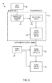
- FIGURE 3 is a block diagram illustrating a system configured to provide information transfer through somatosensation according to one embodiment of the disclosure.
- An input device 302 may receive data for conveyance to a user of the data-to-touch system.
- the input device 302 may be, for example, a microphone configured to receive ambient sounds around the user.
- the input device 302 may also be, for example, a network interface configured to receive data from a remote source, such as the Internet.
- a processing module 310 may be coupled to the input device 302 and to a tactile interface controller 322.
- the processing module 310 processes the data from input device 302 and generates control signals to instruct the tactile interface controller 322 to activate tactile interface devices 108.
- a power supply 326 may be coupled to the tactile interface controller 322 and/or the tactile interface devices 108.
- the processing module 310 may include several modules for performing different operations on data received from the input device 302.
- a sensory data recording module 312 may record sensory data from the environment or Internet into a buffer.
- a computational module 314 may transform, compress, and/or encode data recorded by the sensory data recording module 312.
- the computation module 314 may output data to a tactile interface control module 316, which generates data-frames for playback to the skin by the controller 322.
- the data-frames provide near real-time playback of sensory data by the tactile interface devices 108.
- Data-frames generated by the processing module 310 may be transmitted to the tactile interface controller 322.
- the processing module 310 may reside on the computing device 206 of FIGURE 2 .
- the processing module 310 may include microprocessors programmed to perform specific tasks or the processing module 310 may include computer program code that when executed by a general purpose computer processing unit (CPU) may configure the CPU to perform specific tasks.
- CPU general purpose computer processing unit
- the tactile interface controller 322 may receive the encoded data-frames from the processing module 310 and control the tactile interface devices 108, by turning them on and off, modulating their intensity (such as frequency or amplitude of vibration, or magnitude of electrical stimulation), encoding more complex patterns to induce a sensation of texture, and/or combining actions of multiple tactile interface devices through coordination to produce sensations of sweeps, according to control signals in the received data-frames.
- intensity such as frequency or amplitude of vibration, or magnitude of electrical stimulation
- a sound from the environment may be recorded via a microphone of a smartphone, such as the input device 302.
- the smartphone may include processing module 310 that transforms, compresses, and/or encodes frames of audio (in near real-time) as data-frames for tactile playback to the skin.
- the smartphone then transmits these data-frames to the tactile interface controller over a Bluetooth link.
- the controller 322 may then turn on and off and modulate the tactile interface devices 108 based on the data-frames.
- the tactile interface devices 108 may stimulate touch receptors in the skin, which send information to the brain via electrical impulses from the peripheral nervous system to the brain.
- the tactile interface devices 108 may be remapped in the processing module 310 to provide arbitrary layouts, such as tonotopic layouts and/or anti-tonotopic layouts of the tactile interface devices 108 in clothing.
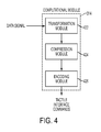
- FIGURE 4 is a block diagram illustrating a computational module for signal processing of data to provide information transfer through somatosensation according to one embodiment of the disclosure.
- the computational module 314 may include modules for processing and interpreting sensory data recorded in the recording module 312.
- the computation module 314 may include a transformation module 422, a compression module 424, and/or an encoding module 426.
- Sending information that has a faster sampling rate or frame-rate than what the skin can support provides challenges not encountered by other sensory substitution devices, such as vision-to-touch systems.
- raw speech (auditory) information may be too fast (0.125 ms/sample) for the skin's temporal acuity ( ⁇ 5-10 ms).
- visual information can be provided at durations as slow as 40 ms, which is within the detection capabilities of skin.
- the data for somatosensation may be transformed to trade off time for space-in other words, the spatial pattern of a high number of tactile interfaces (e.g. motors) can be used to summarize an underlying time-window of fast-changing information.
- the transformation may be performed by transformation module 422.
- a number (which may also be referred to as a plurality) of samples (e.g. audio samples) may be buffered and then transformed or parameterized to a set of values in such a way that these values represent the information contained for all of the samples.
- the resulting values may represent a spatial pattern.
- the resulting values may be fixed over the duration of the collected samples.
- 128 samples of 8 kHz sampled speech audio may be buffered, and then parameterized values extracted from the signals. The values may be fixed over this 16 ms period.
- the skin's temporal acuity constraint may be overcome when the data is transformed.
- transformation may involve a mathematical transformation, such as but not limited to a Discrete Cosine Transform (DCT), or a parameterized modeling of the signal, such as but not limited to Linear Predictive Coding (LPC).
- DCT Discrete Cosine Transform
- LPC Linear Predictive Coding
- Transforms are a lossless mathematical conversion that may trade off time for space and may retain all of the information from the original signal. Parameterized models are lossy but may still produce close approximations of the information contained in the buffered data signal.
- the transformation module 314 may transform the incoming single-dimensional fast-varying sound signal to a multi-dimensional space that varies slow enough for the skin to perceive.
- One method of transforming data performed by the transformation module 422 may be Linear Predictive Filtering/Coding (LPC).
- LPC Linear Predictive Filtering/Coding
- An incoming digitally-sampled signal may be buffered into frames of samples, where the duration of the frame is longer than the acuity of the skin and tactile interfaces. A certain number of samples may correspond to a frame, and after that number of samples is buffered, processing and transformation may be performed on the frame.
- For each framed signal a set of filter coefficients and a simple source signal may be derived. When the source signal is passed through the filter (defined by the derived coefficients), an estimate of the original signal may be reconstructed.
- the filter coefficients may remain fixed for the duration of each frame.
- the parameters for the LPC transformation may include a set of predictive filter coefficients, the energy of the frame, whether or not the frame was voiced, and an estimated fundamental pitch. In one embodiment, only the coefficients and energy may be stored from the LPC transformation
- Signal decomposition may begin with digitally-sampling an audio signal into frames with further processing performed on each frame.
- the signal may then be decomposed into a combination of a fixed set of basis functions.
- the set of basis functions may remain invariant from frame to frame, while the amount of each basis function present in the original signal may vary from frame to frame.
- An example of a signal decomposition is the Fast Fourier Transform (FFT), which decomposes a signal into a sum of sine functions of different frequencies.
- FFT Fast Fourier Transform
- signal decomposition may include Discrete Cosine Transform (DCT), which is similar to FFT but uses a cosine basis function, Wavelet Transform, which is similar to DCT but allows use of a number of different or custom basis functions that are parameterized by how stretched they are in time as opposed to frequency, and Autoencoding Neural Networks, which learn an optimal set of basis functions to represent some training data, parameterized by a desired output dimensionality.
- DCT Discrete Cosine Transform
- Wavelet Transform which is similar to DCT but allows use of a number of different or custom basis functions that are parameterized by how stretched they are in time as opposed to frequency
- Autoencoding Neural Networks which learn an optimal set of basis functions to represent some training data, parameterized by a desired output dimensionality.
- the transformed data may be passed to a compression module 424 to reduce the output dimensionality of the signal. That is, after the information conveyed by the original audio signal has been sufficiently reduced in time by the transformation algorithm, the resulting dimensionality may be larger than can be represented by the array of tactile interface devices that are available in the system. A dimensionality reduction by compressing the transformed signals may reduce the dimensionality to a size appropriate for the tactile interface devices. Additionally, in some embodiments, the range of values for each dimension may exceed a number of different values the skin can discriminate. For example, a given dimension may vary between 0 and 1 with all real numbers in-between.
- the tactile interface device is an eccentric rotating mass motor (ERM)
- the skin may only be able to discriminate between 8-16 different intensity levels. Quantizing the range of possible values for each dimension to 8-16 possible discrete values from 0 to 1 may further compress the transformed audio signal for the tactile interface devices.
- the compression module 424 may limit the range of possible values that can be represented to suit the skin.
- the natural statistics of speech may be used to determine a desired grouping dimensions of output dimensions and compress the data.
- DCT Discrete Cosine Transform
- a 27-cluster 1-D K-means clustering algorithm may then be applied to the peak frequency observations to yield a frequency binning listing the bins that capture the most relevant speech information.
- the number of tactile interface devices may be reduced from 128 components to 27 components through the compression algorithm.
- quantization may include linear mapping, trained statistical mapping by dimension, and global trained statistical mapping.
- level assignments may be divided. For example, if a dimension can take on values on [0 1], the [0 1] values may be quantized to N steps (e.g. 0, 0.25, 0.75, 1), which may be evenly spaced.
- trained statistical mapping by dimension quantitation includes examining a resulting histogram of some training data for each dimension and then determining an uneven spacing of levels based on equal units of area underneath the histogram.
- global trained statistical mapping steps similar to trained statistical mapping by dimension are performed, but the histogram of observations is taken across all dimensions, such that all dimensions use the same level spacing.
- K-Means clustering for transformed data may be performed by the compression module 424.
- K-Means processing may be applied to a frequency-parameterized transform performed by the transformation module 422, such as an FFT, to find the most relevant frequency locations based, at least in part, on some training examples.
- the frequency bins generated by the transformation module 422 may be reduced to K larger bands by the compression module 424.
- auto-encoding neural networks may wrap dimensionality reduction into the transformation phase itself.
- an optimal set of basis functions parameterized by a desired dimensionality may be derived by training an autoencoder neural network.
- an audio signal is processed by transformation module 422 and/or compression module 424, the resulting data may be applied to the skin through the actuation of tactile interface devices.
- An encoding module 426 may receive the data and generate control signals for the tactile interface devices, which map the data signals to tactile interface devices. The mapping may be based, at least in part, on a physical layout for the tactile interface devices, which may be customized to enhance acuity for certain applications.
- decomposition-based transform processing may be performed by the encoding module 426.
- a 1:1 mapping is obtained where each tactile interface devices is assigned to one dimension of output.
- the tactile interface device may be actuated monotonically based on the quantized value of the data. For example, if a dimension of output has a value of zero, the element is turned off. If the dimension is the maximum quantized value, the element may be actuated at a maximum level.
- the encoding module 426 may generate data-frames with control signals to activate tactile interface devices according to the mapping.
- LPC Linear Predictive Filtering/Coding
- Each frame may produce a set of filter coefficients and an energy parameter. These coefficients may be converted to frequency-locations in a line spectral pair (LSP) representation. Unlike a decomposition transform where each dimension represents how much of a basis function is present, the LSPs specify where the most relevant frequencies are for each frame of audio. Any tactile elements that are turned on for a given frame may be assigned a stimulus intensity level that is mapped to the frame's quantized energy parameter. In one embodiment using LSP, all active devices are assigned the same intensity level within each frame. The intensity and active elements may vary from frame to frame, but within a single frame all active devices operate at the same intensity.
- single global axis mapping may be performed by the encoding module 426.
- the possible range of frequencies may be discretized to a set of bands based on the number of tactile interface devices in the array.
- each element may represent a band of frequencies.
- the nearest (in frequency-space) tactile element may be turned on for each LSP by control signals generated by the encoding module 426. For example, if there are six LSPs, six tactile elements may be turned on for each frame, unless LSPs happen to fall in the same quantized frequency band.
- multiple local axis mapping may be performed by the encoding module 426. This mapping is similar to single global axis mapping, but each LSP is given a different set of tactile interface devices to represent a range of frequencies. For example, if there are six LSPs then there may be six axis.
- coded local axis mapping may be performed by the encoding module 426. This mapping is similar to multiple local axis mapping, in that each LSP is given a different set of axis representative of the frequency domain.
- tactile interface devices may be mapped to a frequency using a tree-type code. For example, a binary code with two levels (four tactile elements total) may be used for the tree-type code. The first two elements may represent a top-half and bottom of the entire frequency range. The next two elements may represent either the top two quarters or bottom two quarters as a function of the first level.
- a pre-processing module may perform signal processing operations on the data signal prior to the transformation module 422. Pre-processing may enhance the resulting output quality of subsequent processing by the transformation module 422, the compression module 424, and the encoding module 426. Pre-processing may include, for example, noise reduction. Pre-processing may also include, for example, gating such that if the overall energy of the data signal is below a threshold within a given analysis window or data frame, the data signal may be zeroed for that window. Pre-processing may further include spectral subtraction, such that if the overall energy of the signal is below a threshold within a given analysis window or data frame, the spectral footprint of the signal's spectrogram is subtracted the from subsequent frames.
- a physical layout for the tactile interface devices may be stored in a file accessible by the encoding module 426 and used as part of the mapping process described above.
- the smart phone 206 of FIGURE 2 may receive an identification from the microcontroller 204 of a layout of the tactile interface devices 108.
- the user may input to the smart phone 206 a layout of the tactile interface devices 108.
- the physical layout of the tactile interface devices 108 may be selected to improve the relevance of information being mapped to the tactile interface devices.
- the computational module 314 may be used to assist in the selection of a physical layout for the tactile interface devices.
- a 2-D tonotopic layout may be created that is agnostic of the type of decomposition used.
- training data may be passed through the transformation module 422 and the compression module 424 to obtain example signals.
- a correlation matrix may be calculated for the data.
- a dissimilarity/distance matrix may be calculated by subtracting from 1 the correlation matrix.
- multi-dimensional scaling may be performed on the this distance matrix to obtain a two-dimensional layout that is tuned to the natural statistics for speech audio.
- a column layout may be created for each axis. Then, as LSPs are produced in a sorted order, columns may be ordered from left-to-right by increasing frequency.
- FIGURE 5 is a flow chart illustrating a method for providing information transfer through somatosensation according to one embodiment of the disclosure.
- a method 500 begins with buffering data samples, such as audio samples, from a data signal at block 502.
- the data samples of block 502 may be transformed from the time domain to the space domain.
- the transformed data samples of block 504 may be compressed and/or quantized to reduce a dimensionality of the transformed data samples.
- the compressed data samples may be mapped to tactile interface devices. Control signals for the tactile interface devices may be generated from the mappings of block 508.
- the method 500 of FIGURE 5 may operate on the computational module 314 to process, for example, audio signals or any other type of data. Processing of non-audio data may be similar to that described above with reference to FIGURE 5 and the other figures presented herein.
- data processing by the processing computation module 314 may include representation processing, transformation processing if the data is too fast for skin, dimensionality reduction processing if dimensionality exceeds the number of tactile interface devices, and/or quantization based on representation capability of each tactile interface device.
- the data may be transformed.
- a DCT may collect up N-samples and translate them to an N-dimensional sample, where the information may be fixed for the duration of those N-Samples.
- an N-point 1-D DCT may be applied to each stock, which produces a 10xN dimensional output.
- a 10-D DCT may be applied to the stock data.
- DCT is used as an example, other methods, such as Autoencoding Neural Networks, may be used to transform non-audio data.
- the dimensionality may be reduced through compression if the signal is highly dimensional and there are a limited number of tactile interface devices.
- Speech data may be transformed into a high-dimensional signal because a large number of samples are collected in an effort to "slow down" the information rate for skin.
- a similar issue arises for certain non-audio data, such as stock market or weather data where a large number of stocks or weather locations are being tracked.
- Dimensionality reduction may be accomplished through a number of methods, such as Dictionary Coding with K-Means as described above, using K-Means to find the most important dimensions to collapse to such as used in the DCT, through a parameter of autoencoding neural networks, or through Singular Value Decomposition (SVD).
- the resulting data may be quantized for the tactile interface devices. Quantization may be performed by statistical processes, such as histogram sweeping and K-Means averaging. In histogram sweeping, data may be processed and for each dimension, a histogram of the resulting samples may be generated. Quantization boundaries may be derived as equal area regions, where the area is defined by the number of values to represent. In K-Means averaging, data may be processed and, for each dimension, a histogram of the resulting samples may be generated. Then, the number of clusters may be set to be the number of output values capable of being represented by the tactile interface device.
- K-Means averaging data may be processed and, for each dimension, a histogram of the resulting samples may be generated.
- K-Means may be performed on the histogram for each dimension by running multiple times, each time with different cluster centroid initializations, and averaging the sorted results.
- the 1-D centroids may be quantized values to use for mapping the unquantized data. After quantizing the data, the data may be mapped to the tactile interface array.
- FIGURE 6 is a graph illustrating assignment of frequency bins according to one embodiment of the disclosure.
- a spectrum 600 shows a range of frequencies between 0 to 4000 Hertz common to speech audio.
- the spectrum 600 may be divided into bins 602A, 602B, ..., 602N.
- Each of the bins may be assigned to a tactile interface device. For example, if there are 10 tactile interface devices there may be 10 frequency bins.
- a quantized value for each of the bins 602A-N may be generated by the compression module 424 of FIGURE 4 .
- the quantized value for those bins may be used by the encoding module 426 to generate control signals to activate, at various levels corresponding to the quantized value, the corresponding tactile interface devices by mapping those signals to tactile interface devices.
- the bins 602A-N of FIGURE 6 may be selected based on natural statistics of speech. In one example, if DCT transformations are used, data may be produced that is sorted by frequency. The grouping or layout of bins 602A-N may then be ordered accordingly. More generically, recorded speech across different speakers may be processed through the compression module 424 to produce N-dimensional frames of data and identify statistically how dimensions co-occur with one another. A selection of frequency bins 602A-N and a corresponding physical layout of tactile interface devices may be generated such that dimensions that tend to co-occur are placed close together, and those that tend to not co-occur are spaced further apart, or vice-versa.
- FIGURE 7 is a flow chart illustrating a method for developing a mapping of frequency bins to individual tactile interface devices of an array of tactile interface devices according to one embodiment of the disclosure.
- a method 700 begins at block 702 with receiving a data set of recorded speech.
- N-dimensional samples of the data of block 702 may be produced by the computational module 314.
- statistical correlations are determined between the samples.
- the processed data frames may be used to calculate a correlation matrix.
- the correlation matrix may be an NxN matrix, where an element in row i col j is a measure of the statistical dependency of the ith and jth dimensions.
- the correlation matrix is subtracted from 1, if co-occurring dimensions are to be physically placed closer to one another.
- the resulting correlation matrix provides a notion of distance or dissimilarity.
- the correlation matrix may be processed by a Multi-Dimensional-Scaling (MDS) algorithm to find a physical layout for where each dimension should be placed in a 2-D space corresponding to locations of the tactile interface devices.
- MDS Multi-Dimensional-Scaling
- FIGURE 8 is a flow chart illustrating a method of processing data for providing information transfer through somatosensation using a transform according to one embodiment of the disclosure.
- a method 800 begins at block 802 with collecting N samples of buffered data, such as collecting 128 sample frames of 8 kHz sampled audio.
- a DCT is performed on each of the N samples of buffered data to obtain N coefficient bins.
- the DCT When, the DCT is performed on 128-sample frames, the DCT produces 128 temporally static coefficients "bins.” In one embodiment, negative coefficients may be set to zero (for tactile mapping purposes).
- the N coefficient bins for the buffered data may be compressed to Y coefficient bins corresponding to Y tactile interface devices. In one embodiment, the coefficients may each be quantized to N bits (2 ⁇ N possible values), which are then mapped to a tactile stimulus intensity for each tactile interface device.
- control signals may be generated for the Y tactile interface devices based on the Y coefficient bins of block 806.
- the compression of block 806 may include dimensionality reduction based on a clustering algorithm, such as a K-Means algorithm.
- the dimensionality reduction may include accessing a configuration file generated offline (in non-real time).
- the configuration file may be created by accessing a large data set of recorded speech and performing an N-Sample DCT across the data, which produces N-dimensional frames of data. For each frame, Z dimensions/indices may be found containing the largest values and those indices appended into a list/vector. This list may be a 1-D list, where each index is not representative of a dimension but of a sample.
- a K-Means clustering algorithm may then be executed on this list to form Y clusters, thus finding a set of Y representative DCT indices to represent the data.
- FIGURE 8 represents one specific application of the method 500 of FIGURE 5 using DCT
- other processing may be used within the method 500 of FIGURE 5 .
- performing high-throughput sensory substitution may be performed with linear predicting coding (LPC) as described with reference to FIGURE 9.
- FIGURE 9 is a flow chart illustrating a method of processing data for providing information transfer through somatosensation using linear predictive coding (LPC) according to one embodiment of the disclosure.
- a method 900 may include at block 902 collecting N samples of buffered data.
- a digital finite impulse response (FIR) filter may be derived for each of the N samples, each filter having coefficients that approximate the buffered data.
- the coefficients may be static for the duration of the N samples.
- FIR digital finite impulse response
- LSPs Line Spectral Pairs
- a set of tactile interface devices may represent a quantized array of frequencies, in which for each LSP frequency value in a given frame, a representative tactile interface device may be turned on based on control signals generated at block 908.
- the data-to-touch system described above creates a generalized framework for designing devices to send streams of information to the brain for sensory processing via unusual sensory modalities.
- the system described above may convey information including weather data, stock market data, biological signatures (glucose levels, heart-rate, etc.) of one's self, another individual, or groups of individuals, social media data (e.g. message feeds), and/or sensory information outside the range of normal perception (e.g. supersonic or subsonic auditory information).
- FIGURE 10 illustrates a computer system 1000 adapted according to certain embodiments of the computing device 206 or microcontroller 104.
- the central processing unit (“CPU") 1002 is coupled to the system bus 1004. Although only a single CPU is shown, multiple CPUs may be present.
- the CPU 1002 may be a general purpose CPU or microprocessor, graphics processing unit (“GPU”), and/or microcontroller.
- the present embodiments are not restricted by the architecture of the CPU 1002 so long as the CPU 1002, whether directly or indirectly, supports the operations as described herein.
- the CPU 1002 may execute the various logical instructions according to the present embodiments.
- the computer system 1000 may also include random access memory (RAM) 1008, which may be synchronous RAM (SRAM), dynamic RAM (DRAM), synchronous dynamic RAM (SDRAM), or the like.
- RAM random access memory
- the computer system 1000 may utilize RAM 1008 to store the various data structures used by a software application.
- the computer system 1000 may also include read only memory (ROM) 1006 which may be PROM, EPROM, EEPROM, optical storage, or the like.
- ROM read only memory
- the ROM may store configuration information for booting the computer system 1000.
- the RAM 1008 and the ROM 1006 hold user and system data, and both the RAM 1008 and the ROM 1006 may be randomly accessed.
- the computer system 1000 may also include an input/output (I/O) adapter 1010, a communications adapter 1014, a user interface adapter 1016, and a display adapter 1022.
- the I/O adapter 1010 and/or the user interface adapter 1016 may, in certain embodiments, enable a user to interact with the computer system 1000.
- the display adapter 1022 may display a graphical user interface (GUI) associated with a software or web-based application on a display device 1024, such as a monitor or touch screen.
- GUI graphical user interface
- the I/O adapter 1010 may couple one or more storage devices 1012, such as one or more of a hard drive, a solid state storage device, a flash drive, and a compact disc (CD) drive to the computer system 1000.
- the data storage 1012 may be a separate server coupled to the computer system 1000 through a network connection to the communications adapter 1014.
- the communications adapter 1014 may be adapted to couple the computer system 1000 to the network, which may be one or more of a LAN, WAN, and/or the Internet.
- the user interface adapter 1016 may couple user input devices, such as a keyboard 1020, a pointing device 1018, and/or a touch screen (not shown) to the computer system 1000.
- the keyboard 1020 may be an on-screen keyboard displayed on a touch panel.
- the display adapter 1022 may be driven by the CPU 1002 to control the display on the display device 1024. Any of the devices 1002-1022 may be physical and/or logical.
- the applications of the present disclosure are not limited to the architecture of computer system 1000. Rather the computer system 1000 is provided as an example of one type of computing device that may be adapted to perform the functions of the computing device 206 or microcontroller 104 of FIGURES 1 and 2 .
- any suitable processor-based device may be utilized including, without limitation, personal data assistants (PDAs), tablet computers, smartphones, computer game consoles, and multi-processor servers.
- PDAs personal data assistants
- the systems and methods of the present disclosure may be implemented on application specific integrated circuits (ASIC), very large scale integrated (VLSI) circuits, or other circuitry.
- ASIC application specific integrated circuits
- VLSI very large scale integrated circuits
- persons of ordinary skill in the art may utilize any number of suitable structures capable of executing logical operations according to the described embodiments.
- the computer system may be virtualized for access by multiple users and/or applications.
- Computer-readable media includes physical computer storage media.
- a storage medium may be any available medium that can be accessed by a computer.
- such computer-readable media can comprise RAM, ROM, EEPROM, CD-ROM or other optical disk storage, magnetic disk storage or other magnetic storage devices, or any other medium that can be used to store desired program code in the form of instructions or data structures and that can be accessed by a computer.
- Disk and disc includes compact discs (CD), laser discs, optical discs, digital versatile discs (DVD), floppy disks and blu-ray discs. Generally, disks reproduce data magnetically, and discs reproduce data optically. Combinations of the above should also be included within the scope of computer-readable media. Additionally, the firmware and/or software may be executed by processors integrated with components described above.
- instructions and/or data may be provided as signals on transmission media included in a communication apparatus.
- a communication apparatus may include a transceiver having signals indicative of instructions and data. The instructions and data are configured to cause one or more processors to implement the functions outlined in the claims.
Abstract
Description
- This invention was made with government support under Grant # 5T32EB006350-05 awarded by National Institutes of Health (NIH). The government has certain rights in the invention.
- The instant disclosure relates to providing information through touch sensation. More specifically, this disclosure relates to high-information rate substitution devices (such as, for hearing).
- There are at least 2 million functionally deaf individuals in the United States, and an estimated 53 million worldwide. Auditory perception is an important part of an individual's integration into society because much of a person's interactions with other people and electronic and mechanical devices is through audible information. For deaf individuals, conversing with friends and family, interacting with mobile devices, watching television, and hearing cars and other nearby machinery can be difficult or impossible. Without auditory perception, deaf individuals face operational difficulties, entertainment difficulties, and safety difficulties.
- One conventional tool available for deaf individuals is the cochlear implant. However, cochlear implants (CI) are not a viable hearing solution for a large fraction of the deaf individuals. One reason is cost: as a lower bound, the overall cost of a CI implantation procedure and subsequent follow-ups is $40,000. This places CIs out of economic reach for many. Additionally, CIs require an invasive surgery. Furthermore, CIs have limited benefits in early-onset deaf adults who are receiving the CI after the age of 12. Thus, not only is the CI an expensive and the implantation a dangerous surgical process, but the CI must be implanted while the individual is young. This limits options for deaf individuals who seek auditory perception later in life.
- The problems described above underscore the need for a low-cost, non-invasive hearing solution, and one that can work for adults who have been deaf since birth. One conventional solution is to use sound-to-touch sensory substitution devices. However, a successful sound-to-touch sensory substitution device has yet to be developed. Sound-to-touch devices as an aid for hearing have been researched in the past. However, such devices have been unable to achieve a sufficient efficacy to act as a full substitution for hearing and instead only act as a hearing "aid," rather than as a substitution device. These devices generally rely on band-pass filtering an audio signal and playing this filtered output to the skin over vibrating solenoids. These solenoids operate at a fixed frequency of less than half the bandwidth of some of these band-passed channels, leading to aliasing noise. Thus, the touch representation of received audio sounds is inaccurate and also insufficiently accurate enough to provide a substitute for hearing the audio sounds. Furthermore, the limited bandwidth available for conveying information restricts the application of these prior sound-to-touch substitution devices to only low-bandwidth audio applications, without the ability to convey high-throughput data.
- A somatosensation feedback device may provide information to a user by transforming and/or compressing the information and mapping the information to an array of devices in the somatosensation feedback device. In one embodiment, the somatosensation feedback device may be a wearable item or embedded in wearable clothing, such as a vest. The vest may include an array of feedback devices that provide somatosensation feedback, such as vibration or motion. The vibration or motion may convey the transformed and/or compressed information to the user.
- In one embodiment, the vest may be used as a hearing device to provide audio-to-touch transformation of data. The hearing device may provide hearing-to-touch sensory substitution as a therapeutic approach to deafness. Through use of signal processing on received signals, the hearing device may provide better accuracy with the hearing-to-touch sensory substitution by extending beyond the simple filtering of an incoming audio stream as found in previous tactile hearing aids. The signal processing may include low bitrate audio compression algorithms, such as linear predictive coding, mathematical transforms, such as Fourier transforms, and/or wavelet algorithms. The processed signals may activate tactile interface devices that provide touch sensation to a user. For example, the tactile interface devices may be vibrating devices attached to a vest, which is worn by the user. Through use of the signal processing and mapping of processed signals to tactile interface devices, a deaf individual may learn to interpret skin sensations as audible speech and sounds.
- The signal processing for activating tactile interface devices may be performed in real-time through a controller integrated with tactile interface devices or from a separate computing device, such as a smart phone, tablet computer, laptop computer, MP3 player, and/or voice recorder. Users often have one of these computing devices with them, and such a computing device may be used to provide signal processing for the tactile interface devices. In addition to vibrotactile stimulation, electrotactile stimulation, such as against bare skin, may be used provide information transfer through somatosensation. Whether the vest incorporates electrotactile, vibrotactile, or other stimulation, the vest may provide a wearable sound-to-touch sensory substitution system designed for perceiving auditory information, possibly without adjunct information, such as lip reading.
- A wearable hearing-to-touch sensory substitution, such as described in further detail below, may cost less than one thousand dollars and provide hearing substitution without the invasive and dangerous surgery required by cochlear implants (CIs). Further, such a device may benefit deaf adults who were born deaf, a group of individuals for who CIs do not work well. Further, the signal processing, described in further detail below, may overcome temporal limitations of skin-based sensory perception through the use of mathematical transforms and/or parametric modeling. Further, the system for providing hearing-to-touch sensory substitution may also be configured to provide other data, including news, financial information, caller identification, message notification, or the like, to the user through somatosensation.
- According to one embodiment, an apparatus may include one or more microphones, an array of tactile interface devices, and a processing module coupled to the array of tactile interface devices and coupled to the microphone. The processing module may be configured to perform the steps of receiving audio samples of an audio signal from the microphone; transforming the audio samples from a time domain to a space domain; compressing the transformed audio samples; and/or generating control signals for operating the array of tactile interface devices by mapping the compressed audio samples to individual devices of the array of tactile interface devices.
- According to another embodiment, a method may include receiving samples of a data signal; transforming the samples from a time domain to a space domain; compressing the transformed samples; and/or generating control signals for operating an array of tactile interface devices by mapping the compressed samples to individual devices of the array of tactile interface devices.
- According to yet another embodiment, a computer program product may include a non-transitory computer readable medium having code to perform the steps of receiving samples of a data signal; transforming the samples from a time domain to a space domain; compressing the transformed samples; and/or generating control signals for operating an array of tactile interface devices by mapping the compressed samples to individual devices of the array of tactile interface devices.
- The foregoing has outlined rather broadly the features and technical advantages of the present invention in order that the detailed description of the invention that follows may be better understood. Additional features and advantages of the invention will be described hereinafter that form the subject of the claims of the invention. It should be appreciated by those skilled in the art that the conception and specific embodiment disclosed may be readily utilized as a basis for modifying or designing other structures for carrying out the same purposes of the present invention. It should also be realized by those skilled in the art that such equivalent constructions do not depart from the spirit and scope of the invention as set forth in the appended claims. The novel features that are believed to be characteristic of the invention, both as to its organization and method of operation, together with further objects and advantages will be better understood from the following description when considered in connection with the accompanying figures. It is to be expressly understood, however, that each of the figures is provided for the purpose of illustration and description only and is not intended as a definition of the limits of the present invention.
- For a more complete understanding of the disclosed system and methods, reference is now made to the following descriptions taken in conjunction with the accompanying drawings.
-
FIGURE 1 is an illustration showing a vest with tactile interface devices configured to provide information transfer through somatosensation according to one embodiment of the disclosure. -
FIGURE 2 is an illustration showing a vest with tactile interface devices configured to provide information, received from a smart phone, to a user through somatosensation according to one embodiment of the disclosure. -
FIGURE 3 is a block diagram illustrating a system configured to provide information transfer through somatosensation according to one embodiment of the disclosure. -
FIGURE 4 is a block diagram illustrating a computational module for signal processing of data to provide information transfer through somatosensation according to one embodiment of the disclosure. -
FIGURE 5 is a flow chart illustrating a method for providing information transfer through somatosensation according to one embodiment of the disclosure. -
FIGURE 6 is a graph illustrating assignment of frequency bins according to one embodiment of the disclosure. -
FIGURE 7 is a flow chart illustrating a method for developing a mapping of frequency bins to individual tactile interface devices of an array of tactile interface devices according to one embodiment of the disclosure. -
FIGURE 8 is a flow chart illustrating a method of processing data for providing information transfer through somatosensation using a transform according to one embodiment of the disclosure. -
FIGURE 9 is a flow chart illustrating a method of processing data for providing information transfer through somatosensation using linear predictive coding (LPC) according to one embodiment of the disclosure. -
FIGURE 10 is a block diagram illustrating a computer system according to one embodiment of the disclosure. -
FIGURE 1 is an illustration showing a vest with tactile interface devices configured to provide information transfer through somatosensation according to one embodiment of the disclosure. A data-to-touch system may include avest 100 having an array oftactile interface devices 108 located on a front and back of the best 100. Also mounted to thevest 100 may be amicrocontroller 104, which receives data from aninput device 102, such as a microphone, and converts the data into somatosensation feedback for output by the array oftactile interface devices 108. Thevest 100 may also includebattery pack 106 for operating themicrocontroller 104 and the array oftactile interface devices 108. Theinput device 102 alternatively include other devices, such as data sensors, including a GPS compass, a camera, and/or a network adapter configured to receive a data signal, such as through a cellular or other wireless connection. - When the
input device 102 is a microphone, themicrocontroller 104 may process audio signals received by the microphone and generate signals for activating various devices of the array oftactile interface devices 108. The activation of thetactile interface devices 108 may be in a predictable manner based on the detected audio signal. Thus, a user wearing thevest 100 may learn to associate patterns generated in the array oftactile interface devices 108 with particular audible sounds. The array oftactile interface devices 108 may include tactile and/or haptic interfaces, which may line the inside of an article of clothing, such as thevest 100. The tactile interface devices may include Eccentric Rotating Mass (ERMs) motors, Linear Resonant Actuators (LRAs), Piezoelectric Actuators, Voice/Speaker Coil Actuators, and/or Electrotactile Stimulators (wire leads). - In another embodiment, the processing of audio signals may be performed by a computing device separate from the
vest 100. For example, a user's computing device, such as a smart phone, may communicate with thevest 100 to provide control signals for activating the array oftactile interface devices 108.FIGURE 2 is an illustration showing a vest with tactile interface devices configured to provide information, received from a smart phone, to a user through somatosensation according to one embodiment of the disclosure. Thevest 100 may include a combined battery pack andmicrocontroller 204 coupled to the array oftactile interface devices 108. Themicrocontroller 204 ofsystem 200 may be less sophisticated than themicrocontroller 104 ofFIGURE 1 , because some signal processing may be offloaded to a user'scomputing device 206. Thecomputing device 206, such as a smart phone, may include amicrophone 202 for detecting ambient sounds. Thecomputing device 206 may process received audio signals to generate control signals that are transmitted to themicrocontroller 204 through aconnection 210. Theconnection 210 may be a low-power wireless connection, such as a Bluetooth connection. - The
computing device 206 may be responsible for gathering data either via a connection to the Internet, or through integrated sensors, including a camera, a microphone, and/or an accelerometer. Thedevice 206 may also perform computational processing on the data. After the information is processed, the phone may write data-frames, which include control signals, that instruct themicrocontroller 204 how to present the information to the user through the array oftactile interface devices 108. - The
microcontroller 204 may be part of a control board (not shown) that may be responsible for regulating/providing power to the array oftactile interface devices 108. The control board may also include a Bluetooth interface for collecting and processing data-frames from thecomputing device 206. Themicrocontroller 204 may receive the data-frames and modulate the array oftactile interface devices 108 based, at least in part, on control signals contained in the received data-frames. In one embodiment, the array oftactile interface devices 108 may be controlled through Pulse Width Modulation (PWM). In another embodiment, the array oftactile interface devices 108 may be controlled through custom-generated signals through digital-to-analog converters (DAC or D2A). The control board may also include a wireless transmitter for forwarding data-frames to other control boards, such as through I2C protocol, Bluetooth, or ZigBee. - Operation of a data-to-touch sensory substitution system, such as those described above, may be illustrated in a block diagram.
FIGURE 3 is a block diagram illustrating a system configured to provide information transfer through somatosensation according to one embodiment of the disclosure. Aninput device 302 may receive data for conveyance to a user of the data-to-touch system. Theinput device 302 may be, for example, a microphone configured to receive ambient sounds around the user. Theinput device 302 may also be, for example, a network interface configured to receive data from a remote source, such as the Internet. - A
processing module 310 may be coupled to theinput device 302 and to atactile interface controller 322. Theprocessing module 310 processes the data frominput device 302 and generates control signals to instruct thetactile interface controller 322 to activatetactile interface devices 108. Apower supply 326 may be coupled to thetactile interface controller 322 and/or thetactile interface devices 108. - The
processing module 310 may include several modules for performing different operations on data received from theinput device 302. A sensorydata recording module 312 may record sensory data from the environment or Internet into a buffer. Acomputational module 314 may transform, compress, and/or encode data recorded by the sensorydata recording module 312. Thecomputation module 314 may output data to a tactileinterface control module 316, which generates data-frames for playback to the skin by thecontroller 322. In one embodiment, the data-frames provide near real-time playback of sensory data by thetactile interface devices 108. - Data-frames generated by the
processing module 310 may be transmitted to thetactile interface controller 322. In one embodiment, theprocessing module 310 may reside on thecomputing device 206 ofFIGURE 2 . For example, theprocessing module 310 may include microprocessors programmed to perform specific tasks or theprocessing module 310 may include computer program code that when executed by a general purpose computer processing unit (CPU) may configure the CPU to perform specific tasks. Thetactile interface controller 322 may receive the encoded data-frames from theprocessing module 310 and control thetactile interface devices 108, by turning them on and off, modulating their intensity (such as frequency or amplitude of vibration, or magnitude of electrical stimulation), encoding more complex patterns to induce a sensation of texture, and/or combining actions of multiple tactile interface devices through coordination to produce sensations of sweeps, according to control signals in the received data-frames. - In one example operation of a
system 300 ofFIGURE 3 , a sound from the environment may be recorded via a microphone of a smartphone, such as theinput device 302. The smartphone may includeprocessing module 310 that transforms, compresses, and/or encodes frames of audio (in near real-time) as data-frames for tactile playback to the skin. The smartphone then transmits these data-frames to the tactile interface controller over a Bluetooth link. Thecontroller 322 may then turn on and off and modulate thetactile interface devices 108 based on the data-frames. Thetactile interface devices 108 may stimulate touch receptors in the skin, which send information to the brain via electrical impulses from the peripheral nervous system to the brain. Thetactile interface devices 108 may be remapped in theprocessing module 310 to provide arbitrary layouts, such as tonotopic layouts and/or anti-tonotopic layouts of thetactile interface devices 108 in clothing. - Further details regarding the
computational module 314 are shown inFIGURE 4. FIGURE 4 is a block diagram illustrating a computational module for signal processing of data to provide information transfer through somatosensation according to one embodiment of the disclosure. Thecomputational module 314 may include modules for processing and interpreting sensory data recorded in therecording module 312. For example, thecomputation module 314 may include atransformation module 422, acompression module 424, and/or anencoding module 426. - Sending information that has a faster sampling rate or frame-rate than what the skin can support (such as speech audio or stock trading data being streamed form the Internet) provides challenges not encountered by other sensory substitution devices, such as vision-to-touch systems. For example, raw speech (auditory) information may be too fast (0.125 ms/sample) for the skin's temporal acuity (∼5-10 ms). In contrast, visual information can be provided at durations as slow as 40 ms, which is within the detection capabilities of skin. In one embodiment, the data for somatosensation may be transformed to trade off time for space-in other words, the spatial pattern of a high number of tactile interfaces (e.g. motors) can be used to summarize an underlying time-window of fast-changing information.
- The transformation may be performed by
transformation module 422. For example, a number (which may also be referred to as a plurality) of samples (e.g. audio samples) may be buffered and then transformed or parameterized to a set of values in such a way that these values represent the information contained for all of the samples. The resulting values may represent a spatial pattern. The resulting values may be fixed over the duration of the collected samples. In one embodiment, 128 samples of 8 kHz sampled speech audio may be buffered, and then parameterized values extracted from the signals. The values may be fixed over this 16 ms period. Thus, the skin's temporal acuity constraint may be overcome when the data is transformed. In different embodiments, transformation may involve a mathematical transformation, such as but not limited to a Discrete Cosine Transform (DCT), or a parameterized modeling of the signal, such as but not limited to Linear Predictive Coding (LPC). Transforms are a lossless mathematical conversion that may trade off time for space and may retain all of the information from the original signal. Parameterized models are lossy but may still produce close approximations of the information contained in the buffered data signal. - Because skin has a much lower temporal acuity (slower response) than that of the ear, the
transformation module 314 may transform the incoming single-dimensional fast-varying sound signal to a multi-dimensional space that varies slow enough for the skin to perceive. Conventional "tactile hearing aids," such as those referred to in the background, process audio signals by splitting the audio signal into multiple channels using band-pass filtering. The conventional band-pass processing does not change the dimensionality or compress the audio signal as performed in certain embodiments of the present audio-to-speech system. - One method of transforming data performed by the
transformation module 422 may be Linear Predictive Filtering/Coding (LPC). An incoming digitally-sampled signal may be buffered into frames of samples, where the duration of the frame is longer than the acuity of the skin and tactile interfaces. A certain number of samples may correspond to a frame, and after that number of samples is buffered, processing and transformation may be performed on the frame. For each framed signal, a set of filter coefficients and a simple source signal may be derived. When the source signal is passed through the filter (defined by the derived coefficients), an estimate of the original signal may be reconstructed. The filter coefficients may remain fixed for the duration of each frame. The parameters for the LPC transformation may include a set of predictive filter coefficients, the energy of the frame, whether or not the frame was voiced, and an estimated fundamental pitch. In one embodiment, only the coefficients and energy may be stored from the LPC transformation. - Another method of transforming data performed by the
transformation model 422 may include signal decomposition. Signal decomposition may begin with digitally-sampling an audio signal into frames with further processing performed on each frame. The signal may then be decomposed into a combination of a fixed set of basis functions. The set of basis functions may remain invariant from frame to frame, while the amount of each basis function present in the original signal may vary from frame to frame. An example of a signal decomposition is the Fast Fourier Transform (FFT), which decomposes a signal into a sum of sine functions of different frequencies. Other examples of signal decomposition may include Discrete Cosine Transform (DCT), which is similar to FFT but uses a cosine basis function, Wavelet Transform, which is similar to DCT but allows use of a number of different or custom basis functions that are parameterized by how stretched they are in time as opposed to frequency, and Autoencoding Neural Networks, which learn an optimal set of basis functions to represent some training data, parameterized by a desired output dimensionality. - After the signal has been transformed or modeled by
transformation module 422, the transformed data may be passed to acompression module 424 to reduce the output dimensionality of the signal. That is, after the information conveyed by the original audio signal has been sufficiently reduced in time by the transformation algorithm, the resulting dimensionality may be larger than can be represented by the array of tactile interface devices that are available in the system. A dimensionality reduction by compressing the transformed signals may reduce the dimensionality to a size appropriate for the tactile interface devices. Additionally, in some embodiments, the range of values for each dimension may exceed a number of different values the skin can discriminate. For example, a given dimension may vary between 0 and 1 with all real numbers in-between. However, when the tactile interface device is an eccentric rotating mass motor (ERM), the skin may only be able to discriminate between 8-16 different intensity levels. Quantizing the range of possible values for each dimension to 8-16 possible discrete values from 0 to 1 may further compress the transformed audio signal for the tactile interface devices. - In one example of quantization, the
compression module 424 may limit the range of possible values that can be represented to suit the skin. When the data is speech, the natural statistics of speech may be used to determine a desired grouping dimensions of output dimensions and compress the data. As an example, to determine one possible allocation of frequency bands for a Discrete Cosine Transform (DCT)-based transform: for each collapsed bin, 2 hours of sampled natural speech audio may be broken into 16 ms frames (128-point, 8 kHz sampled) on which a DCT is taken. For each output, the five bins with the most energy are appended to a vector. These peak frequencies may be presumed to represent the most important formants, such as spectral energy sweeps that make up phonemes, the fundamental building blocks of speech. A 27-cluster 1-D K-means clustering algorithm may then be applied to the peak frequency observations to yield a frequency binning listing the bins that capture the most relevant speech information. In this example, the number of tactile interface devices may be reduced from 128 components to 27 components through the compression algorithm. - Other examples of quantization may include linear mapping, trained statistical mapping by dimension, and global trained statistical mapping. In linear mapping, level assignments may be divided. For example, if a dimension can take on values on [0 1], the [0 1] values may be quantized to N steps (e.g. 0, 0.25, 0.75, 1), which may be evenly spaced. In trained statistical mapping by dimension, quantitation includes examining a resulting histogram of some training data for each dimension and then determining an uneven spacing of levels based on equal units of area underneath the histogram. In global trained statistical mapping, steps similar to trained statistical mapping by dimension are performed, but the histogram of observations is taken across all dimensions, such that all dimensions use the same level spacing.
- In one example of reducing dimensionality, K-Means clustering for transformed data may be performed by the
compression module 424. K-Means processing may be applied to a frequency-parameterized transform performed by thetransformation module 422, such as an FFT, to find the most relevant frequency locations based, at least in part, on some training examples. After having determined a set of the K most relevant frequency locations, the frequency bins generated by thetransformation module 422 may be reduced to K larger bands by thecompression module 424. - In another example of reducing dimensionality, auto-encoding neural networks may wrap dimensionality reduction into the transformation phase itself. In this example, an optimal set of basis functions parameterized by a desired dimensionality may be derived by training an autoencoder neural network.
- After an audio signal is processed by
transformation module 422 and/orcompression module 424, the resulting data may be applied to the skin through the actuation of tactile interface devices. Anencoding module 426 may receive the data and generate control signals for the tactile interface devices, which map the data signals to tactile interface devices. The mapping may be based, at least in part, on a physical layout for the tactile interface devices, which may be customized to enhance acuity for certain applications. - In one example of mapping the data to tactile interface devices, decomposition-based transform processing may be performed by the
encoding module 426. In this example, a 1:1 mapping is obtained where each tactile interface devices is assigned to one dimension of output. The tactile interface device may be actuated monotonically based on the quantized value of the data. For example, if a dimension of output has a value of zero, the element is turned off. If the dimension is the maximum quantized value, the element may be actuated at a maximum level. Theencoding module 426 may generate data-frames with control signals to activate tactile interface devices according to the mapping. - In another example of mapping the data to tactile interface devices, Linear Predictive Filtering/Coding (LPC) may be performed by the
encoding module 426. Each frame may produce a set of filter coefficients and an energy parameter. These coefficients may be converted to frequency-locations in a line spectral pair (LSP) representation. Unlike a decomposition transform where each dimension represents how much of a basis function is present, the LSPs specify where the most relevant frequencies are for each frame of audio. Any tactile elements that are turned on for a given frame may be assigned a stimulus intensity level that is mapped to the frame's quantized energy parameter. In one embodiment using LSP, all active devices are assigned the same intensity level within each frame. The intensity and active elements may vary from frame to frame, but within a single frame all active devices operate at the same intensity. - In a further example of mapping the data to tactile interface devices, single global axis mapping may be performed by the
encoding module 426. In this example, the possible range of frequencies may be discretized to a set of bands based on the number of tactile interface devices in the array. Thus, each element may represent a band of frequencies. For each output frame, the nearest (in frequency-space) tactile element may be turned on for each LSP by control signals generated by theencoding module 426. For example, if there are six LSPs, six tactile elements may be turned on for each frame, unless LSPs happen to fall in the same quantized frequency band. - In another example of mapping the data to tactile interface devices, multiple local axis mapping may be performed by the
encoding module 426. This mapping is similar to single global axis mapping, but each LSP is given a different set of tactile interface devices to represent a range of frequencies. For example, if there are six LSPs then there may be six axis. - In a further example of mapping the data to tactile interface devices, coded local axis mapping may be performed by the
encoding module 426. This mapping is similar to multiple local axis mapping, in that each LSP is given a different set of axis representative of the frequency domain. However, tactile interface devices may be mapped to a frequency using a tree-type code. For example, a binary code with two levels (four tactile elements total) may be used for the tree-type code. The first two elements may represent a top-half and bottom of the entire frequency range. The next two elements may represent either the top two quarters or bottom two quarters as a function of the first level. - According to one embodiment, a pre-processing module (not shown) may perform signal processing operations on the data signal prior to the
transformation module 422. Pre-processing may enhance the resulting output quality of subsequent processing by thetransformation module 422, thecompression module 424, and theencoding module 426. Pre-processing may include, for example, noise reduction. Pre-processing may also include, for example, gating such that if the overall energy of the data signal is below a threshold within a given analysis window or data frame, the data signal may be zeroed for that window. Pre-processing may further include spectral subtraction, such that if the overall energy of the signal is below a threshold within a given analysis window or data frame, the spectral footprint of the signal's spectrogram is subtracted the from subsequent frames. - A physical layout for the tactile interface devices may be stored in a file accessible by the
encoding module 426 and used as part of the mapping process described above. For example, thesmart phone 206 ofFIGURE 2 may receive an identification from themicrocontroller 204 of a layout of thetactile interface devices 108. Alternatively, the user may input to the smart phone 206 a layout of thetactile interface devices 108. The physical layout of thetactile interface devices 108 may be selected to improve the relevance of information being mapped to the tactile interface devices. - The
computational module 314 may be used to assist in the selection of a physical layout for the tactile interface devices. In one example of mapping the tactile interface devices for decomposition-based transforms, a 2-D tonotopic layout may be created that is agnostic of the type of decomposition used. First, training data may be passed through thetransformation module 422 and thecompression module 424 to obtain example signals. Then, a correlation matrix may be calculated for the data. Next, a dissimilarity/distance matrix may be calculated by subtracting from 1 the correlation matrix. Then, multi-dimensional scaling may be performed on the this distance matrix to obtain a two-dimensional layout that is tuned to the natural statistics for speech audio. In another example of mapping the tactile interface devices for Linear Predictive Filtering/Coding (LPC), a column layout may be created for each axis. Then, as LSPs are produced in a sorted order, columns may be ordered from left-to-right by increasing frequency. - One method performed by the
computational module 314 is illustrated inFIGURE 5. FIGURE 5 is a flow chart illustrating a method for providing information transfer through somatosensation according to one embodiment of the disclosure. Amethod 500 begins with buffering data samples, such as audio samples, from a data signal atblock 502. Atblock 504, the data samples ofblock 502 may be transformed from the time domain to the space domain. Atblock 506, the transformed data samples ofblock 504 may be compressed and/or quantized to reduce a dimensionality of the transformed data samples. Then, atblock 508, the compressed data samples may be mapped to tactile interface devices. Control signals for the tactile interface devices may be generated from the mappings ofblock 508. - The
method 500 ofFIGURE 5 may operate on thecomputational module 314 to process, for example, audio signals or any other type of data. Processing of non-audio data may be similar to that described above with reference toFIGURE 5 and the other figures presented herein. In general, data processing by theprocessing computation module 314 may include representation processing, transformation processing if the data is too fast for skin, dimensionality reduction processing if dimensionality exceeds the number of tactile interface devices, and/or quantization based on representation capability of each tactile interface device. - Non-audio data in an information stream, agnostic of source, may be adapted to be represented as a numerical N-dimensional time-varying stream of data, where each sample-point contains N-values. For example, if a user is observing ten stocks, a 10-dimensional time-varying stream may be produced. Stocks and other data, such as temperature weather data begin as numerical data. Non-numerical data, such as whether the weather condition is cloudy, raining, or sunny, may be considered categorical variables that can be represented in numerical variables based on a mapping. For example, clouds = -1, raining = 0, and sunny = 1.
- After the non-audio data is represented as numerical data, the data may be transformed. For example, agnostic to the source of data, a DCT may collect up N-samples and translate them to an N-dimensional sample, where the information may be fixed for the duration of those N-Samples. In the stock market example, where a user is tracking 10 stocks, an N-point 1-D DCT may be applied to each stock, which produces a 10xN dimensional output. Alternatively, a 10-D DCT may be applied to the stock data. Although DCT is used as an example, other methods, such as Autoencoding Neural Networks, may be used to transform non-audio data.
- After transforming the non-audio data, the dimensionality may be reduced through compression if the signal is highly dimensional and there are a limited number of tactile interface devices. Speech data may be transformed into a high-dimensional signal because a large number of samples are collected in an effort to "slow down" the information rate for skin. A similar issue arises for certain non-audio data, such as stock market or weather data where a large number of stocks or weather locations are being tracked. Dimensionality reduction may be accomplished through a number of methods, such as Dictionary Coding with K-Means as described above, using K-Means to find the most important dimensions to collapse to such as used in the DCT, through a parameter of autoencoding neural networks, or through Singular Value Decomposition (SVD).
- After representing data, transforming the data, and/or compressing the data, the resulting data may be quantized for the tactile interface devices. Quantization may be performed by statistical processes, such as histogram sweeping and K-Means averaging. In histogram sweeping, data may be processed and for each dimension, a histogram of the resulting samples may be generated. Quantization boundaries may be derived as equal area regions, where the area is defined by the number of values to represent. In K-Means averaging, data may be processed and, for each dimension, a histogram of the resulting samples may be generated. Then, the number of clusters may be set to be the number of output values capable of being represented by the tactile interface device. K-Means may be performed on the histogram for each dimension by running multiple times, each time with different cluster centroid initializations, and averaging the sorted results. The 1-D centroids may be quantized values to use for mapping the unquantized data. After quantizing the data, the data may be mapped to the tactile interface array.
- Referring back to
FIGURE 5 , block 508 describes the mapping of data to tactile interface devices. An illustration of the mappings of various frequencies of audible speech to tactile interface devices is shown inFIGURE 6. FIGURE 6 is a graph illustrating assignment of frequency bins according to one embodiment of the disclosure. Aspectrum 600 shows a range of frequencies between 0 to 4000 Hertz common to speech audio. Thespectrum 600 may be divided intobins bins 602A-N may be generated by thecompression module 424 ofFIGURE 4 . The quantized value for those bins may be used by theencoding module 426 to generate control signals to activate, at various levels corresponding to the quantized value, the corresponding tactile interface devices by mapping those signals to tactile interface devices. - The
bins 602A-N ofFIGURE 6 may be selected based on natural statistics of speech. In one example, if DCT transformations are used, data may be produced that is sorted by frequency. The grouping or layout ofbins 602A-N may then be ordered accordingly. More generically, recorded speech across different speakers may be processed through thecompression module 424 to produce N-dimensional frames of data and identify statistically how dimensions co-occur with one another. A selection offrequency bins 602A-N and a corresponding physical layout of tactile interface devices may be generated such that dimensions that tend to co-occur are placed close together, and those that tend to not co-occur are spaced further apart, or vice-versa. - The selection of locations for
bins 602A-N may be performed in non-real time and stored as a configuration file for reference.FIGURE 7 is a flow chart illustrating a method for developing a mapping of frequency bins to individual tactile interface devices of an array of tactile interface devices according to one embodiment of the disclosure. Amethod 700 begins atblock 702 with receiving a data set of recorded speech. Atblock 704, N-dimensional samples of the data ofblock 702 may be produced by thecomputational module 314. Atblock 706, statistical correlations are determined between the samples. Atblock 708, the processed data frames may be used to calculate a correlation matrix. The correlation matrix may be an NxN matrix, where an element in row i col j is a measure of the statistical dependency of the ith and jth dimensions. The correlation matrix is subtracted from 1, if co-occurring dimensions are to be physically placed closer to one another. The resulting correlation matrix provides a notion of distance or dissimilarity. Atblock 710, the correlation matrix may be processed by a Multi-Dimensional-Scaling (MDS) algorithm to find a physical layout for where each dimension should be placed in a 2-D space corresponding to locations of the tactile interface devices. - Referring back to
FIGURE 5 , themethod 500 describes a generic process for mapping audio-to-touch sensory substitution. One specific method for performing high-throughput sensory substitution using Discrete Cosine Transform (DCT) is described with respect toFIGURE 8. FIGURE 8 is a flow chart illustrating a method of processing data for providing information transfer through somatosensation using a transform according to one embodiment of the disclosure. Amethod 800 begins atblock 802 with collecting N samples of buffered data, such as collecting 128 sample frames of 8 kHz sampled audio. Atblock 804, a DCT is performed on each of the N samples of buffered data to obtain N coefficient bins. When, the DCT is performed on 128-sample frames, the DCT produces 128 temporally static coefficients "bins." In one embodiment, negative coefficients may be set to zero (for tactile mapping purposes). Atblock 806, the N coefficient bins for the buffered data may be compressed to Y coefficient bins corresponding to Y tactile interface devices. In one embodiment, the coefficients may each be quantized to N bits (2^N possible values), which are then mapped to a tactile stimulus intensity for each tactile interface device. Atblock 808, control signals may be generated for the Y tactile interface devices based on the Y coefficient bins ofblock 806. - The compression of
block 806 may include dimensionality reduction based on a clustering algorithm, such as a K-Means algorithm. In the case of the DCT, the dimensionality reduction may include accessing a configuration file generated offline (in non-real time). The configuration file may be created by accessing a large data set of recorded speech and performing an N-Sample DCT across the data, which produces N-dimensional frames of data. For each frame, Z dimensions/indices may be found containing the largest values and those indices appended into a list/vector. This list may be a 1-D list, where each index is not representative of a dimension but of a sample. A K-Means clustering algorithm may then be executed on this list to form Y clusters, thus finding a set of Y representative DCT indices to represent the data. - In one example, there are 128 bins (ordered from
index 0 to index 127) and the K-Means algorithm may select the indices Y=[5, 19, 94, 120]. Then, for each incoming 128-sample frame of data, a 128-pt DCT is processing to generate a data frame with 128 bins. A L1/L2 distance is used to collapse each bin into the nearest representative bin Y. Thus, the values inbins 0, 1, 2, 3, 4, 5, 6, 7, 8, 9, 10, 11 (the closest bins to 5 from Y) may be collapsed to a single value, which may be either an average value, a weighted average, a max value, a median value, or any other statistically generated value from that set. The process may be repeated for the other indices identified by the K-Means algorithm. - Although
FIGURE 8 represents one specific application of themethod 500 ofFIGURE 5 using DCT, other processing may be used within themethod 500 ofFIGURE 5 . For example, performing high-throughput sensory substitution may be performed with linear predicting coding (LPC) as described with reference toFIGURE 9. FIGURE 9 is a flow chart illustrating a method of processing data for providing information transfer through somatosensation using linear predictive coding (LPC) according to one embodiment of the disclosure. Amethod 900 may include atblock 902 collecting N samples of buffered data. Atblock 904, a digital finite impulse response (FIR) filter may be derived for each of the N samples, each filter having coefficients that approximate the buffered data. In one embodiment, the coefficients may be static for the duration of the N samples. These filter coefficients may be used to reconstruct a close approximation of the input original signal. Atblock 906, these filter coefficients may be converted to a frequency-domain representation of Line Spectral Pairs (LSPs), which represent frequency locations. A set of tactile interface devices may represent a quantized array of frequencies, in which for each LSP frequency value in a given frame, a representative tactile interface device may be turned on based on control signals generated atblock 908. - Beyond applications for hearing, the data-to-touch system described above creates a generalized framework for designing devices to send streams of information to the brain for sensory processing via unusual sensory modalities. The system described above may convey information including weather data, stock market data, biological signatures (glucose levels, heart-rate, etc.) of one's self, another individual, or groups of individuals, social media data (e.g. message feeds), and/or sensory information outside the range of normal perception (e.g. supersonic or subsonic auditory information).
-
FIGURE 10 illustrates acomputer system 1000 adapted according to certain embodiments of thecomputing device 206 ormicrocontroller 104. The central processing unit ("CPU") 1002 is coupled to thesystem bus 1004. Although only a single CPU is shown, multiple CPUs may be present. TheCPU 1002 may be a general purpose CPU or microprocessor, graphics processing unit ("GPU"), and/or microcontroller. The present embodiments are not restricted by the architecture of theCPU 1002 so long as theCPU 1002, whether directly or indirectly, supports the operations as described herein. TheCPU 1002 may execute the various logical instructions according to the present embodiments. - The
computer system 1000 may also include random access memory (RAM) 1008, which may be synchronous RAM (SRAM), dynamic RAM (DRAM), synchronous dynamic RAM (SDRAM), or the like. Thecomputer system 1000 may utilizeRAM 1008 to store the various data structures used by a software application. Thecomputer system 1000 may also include read only memory (ROM) 1006 which may be PROM, EPROM, EEPROM, optical storage, or the like. The ROM may store configuration information for booting thecomputer system 1000. TheRAM 1008 and theROM 1006 hold user and system data, and both theRAM 1008 and theROM 1006 may be randomly accessed. - The
computer system 1000 may also include an input/output (I/O)adapter 1010, acommunications adapter 1014, auser interface adapter 1016, and adisplay adapter 1022. The I/O adapter 1010 and/or theuser interface adapter 1016 may, in certain embodiments, enable a user to interact with thecomputer system 1000. In a further embodiment, thedisplay adapter 1022 may display a graphical user interface (GUI) associated with a software or web-based application on adisplay device 1024, such as a monitor or touch screen. - The I/
O adapter 1010 may couple one ormore storage devices 1012, such as one or more of a hard drive, a solid state storage device, a flash drive, and a compact disc (CD) drive to thecomputer system 1000. According to one embodiment, thedata storage 1012 may be a separate server coupled to thecomputer system 1000 through a network connection to thecommunications adapter 1014. Thecommunications adapter 1014 may be adapted to couple thecomputer system 1000 to the network, which may be one or more of a LAN, WAN, and/or the Internet. Theuser interface adapter 1016 may couple user input devices, such as akeyboard 1020, apointing device 1018, and/or a touch screen (not shown) to thecomputer system 1000. Thekeyboard 1020 may be an on-screen keyboard displayed on a touch panel. Thedisplay adapter 1022 may be driven by theCPU 1002 to control the display on thedisplay device 1024. Any of the devices 1002-1022 may be physical and/or logical. - The applications of the present disclosure are not limited to the architecture of
computer system 1000. Rather thecomputer system 1000 is provided as an example of one type of computing device that may be adapted to perform the functions of thecomputing device 206 ormicrocontroller 104 ofFIGURES 1 and 2 . For example, any suitable processor-based device may be utilized including, without limitation, personal data assistants (PDAs), tablet computers, smartphones, computer game consoles, and multi-processor servers. Moreover, the systems and methods of the present disclosure may be implemented on application specific integrated circuits (ASIC), very large scale integrated (VLSI) circuits, or other circuitry. In fact, persons of ordinary skill in the art may utilize any number of suitable structures capable of executing logical operations according to the described embodiments. For example, the computer system may be virtualized for access by multiple users and/or applications. - If implemented in firmware and/or software, the functions described above may be stored as one or more instructions or code on a computer-readable medium. Examples include non-transitory computer-readable media encoded with a data structure and computer-readable media encoded with a computer program. Computer-readable media includes physical computer storage media. A storage medium may be any available medium that can be accessed by a computer. By way of example, and not limitation, such computer-readable media can comprise RAM, ROM, EEPROM, CD-ROM or other optical disk storage, magnetic disk storage or other magnetic storage devices, or any other medium that can be used to store desired program code in the form of instructions or data structures and that can be accessed by a computer. Disk and disc includes compact discs (CD), laser discs, optical discs, digital versatile discs (DVD), floppy disks and blu-ray discs. Generally, disks reproduce data magnetically, and discs reproduce data optically. Combinations of the above should also be included within the scope of computer-readable media. Additionally, the firmware and/or software may be executed by processors integrated with components described above.
- In addition to storage on computer readable medium, instructions and/or data may be provided as signals on transmission media included in a communication apparatus. For example, a communication apparatus may include a transceiver having signals indicative of instructions and data. The instructions and data are configured to cause one or more processors to implement the functions outlined in the claims.
- Although the present disclosure and its advantages have been described in detail, it should be understood that various changes, substitutions and alterations can be made herein without departing from the spirit and scope of the disclosure as defined by the appended claims. Moreover, the scope of the present application is not intended to be limited to the particular embodiments of the process, machine, manufacture, composition of matter, means, methods and steps described in the specification. As one of ordinary skill in the art will readily appreciate from the present invention, disclosure, machines, manufacture, compositions of matter, means, methods, or steps, presently existing or later to be developed that perform substantially the same function or achieve substantially the same result as the corresponding embodiments described herein may be utilized according to the present disclosure. Accordingly, the appended claims are intended to include within their scope such processes, machines, manufacture, compositions of matter, means, methods, or steps.
Claims (14)
- An apparatus, comprising:an input device;a processing module configured to control an array of tactile interface devices and coupled to the input device, wherein the processing module is configured to control the array of tactile interface devices by performing the steps of:receiving samples of a data signal from the input device;transforming the data samples into spatial patterns; andgenerating control signals for operating the array of tactile interface devices by mapping the spatial patterns to one or more devices of the array of tactile interface devices.
- The apparatus of claim 1, wherein the processing module is configured to transform the data samples into spatial patterns by transforming the data samples from a time domain to a space domain, and wherein the processing module is further configured to compress the transformed data samples to reduce a dimensionality of the data samples.
- The apparatus of claim 1 or 2, wherein the processing module is configured to transform one or more pluralities of the data samples, each plurality of the data samples being transformed into a corresponding spatial pattern that is fixed for the duration of the plurality of data samples.
- The apparatus of any one of the preceding claims, wherein the tactile interface devices comprise at least one of eccentric rotating mass (ERM) motors, electrotactile leads, piezoelectric interfaces, and/or vibrating solenoids.
- The apparatus of any of the preceding claims, wherein: the input device comprises at least one of a microphone, a network adapter, and a camera; and/or the processing module comprises a smart phone, the input devices comprises a microphone integrated with the smart phone, and the data signal comprises an audio signal.
- The apparatus of any of the preceding claims, further comprising a tactile interface microcontroller coupled to the array of tactile interface devices, wherein the tactile interface microcontroller is configured to receive the generated control signals and activate individual tactile interface devices of the array of tactile interface devices.
- The apparatus of any of the preceding claims, wherein the processing module is configured to transform the data samples with a discrete cosine transform (DCT) to obtain a set of coefficients, wherein, optionally, the processing module is further configured to compress the transformed data samples by reducing the resulting set of coefficients to a smaller second set of coefficients, wherein, optionally, each of the second set of coefficients corresponds to a device in the array of tactile interface devices or may map to a more complex tactile pattern that spans multiple devices in the array of tactile interface devices, and wherein, optionally, the second set of coefficients are mapped to the array of tactile interface devices based on mapping data retrieved from a configuration file.
- The apparatus of any of the preceding claims, wherein the processing module is configured to transform the data samples by deriving a digital finite impulse response (FIR) filter for one or more data samples, wherein the produced FIR filter for a data sample comprises coefficients that approximate the data sample, wherein, optionally, the processing module is configured to translate the predictive FIR coefficients for a data sample into a frequency-domain representation set of line spectral pairs (LSPs), and wherein, optionally, the processing module is configured to generate control signals by quantizing each LSP from the set of LSPs based on a mapping from this set to the array of tactile interface devices.
- A method, comprising:receiving samples of a data signal;transforming the samples from a time domain to a space domain to reduce a data rate of the samples;compressing the transformed samples to reduce a dimensionality of the transformed samples; andgenerating control signals for operating an array of tactile interface devices by mapping the compressed samples to one or more devices of the array of tactile interface devices.
- The method of claim 9, wherein the step of receiving samples of a data signal comprises receiving audio samples of an audio signal.
- The method of claim 9 or 10, wherein the step of transforming the samples comprises transforming one or more pluralities of the samples, each plurality of the samples being transformed into a corresponding spatial pattern that is fixed for the duration of the plurality of data samples.
- The method of any of claims 9-11, wherein the step of transforming the samples comprises transforming the samples with a discrete cosine transform (DCT) to obtain a set of coefficients, wherein, optionally, the step of compressing the transformed samples comprises compressing the transformed samples by reducing the dimensionality of the resulting set of coefficients to a smaller second set of coefficients, wherein each of the second set of coefficients corresponds to one or more devices of the array of tactile interface devices, and wherein, optionally, the method further comprises:retrieving a configuration file comprising mapping data; andmapping the second set of coefficients to the array of tactile interface devices based on the mapping data, wherein the generated control signals are based, at least in part, on the mapping of the first or second set of coefficients to the array of tactile interface devices.
- The method of any of claims 9-12, wherein the step of transforming the samples comprises transforming the samples by deriving a digital finite impulse response (FIR) filter for a set of one or more samples, wherein the produced FIR filter for a sample comprises coefficients that approximate the sample, wherein, optionally, the step of compressing the samples comprises converting the predicted FIR coefficients for a sample into a frequency-domain representation set of line spectral pairs (LSPs), and wherein, optionally, the step of generating control signals comprises quantizing each LSP from the set of LSPs based on a mapping from this set to the array of tactile interface devices.
- A computer program product, comprising:a non-transitory computer readable medium comprising code to perform the method of any of claims 9-13.
Priority Applications (1)
| Application Number | Priority Date | Filing Date | Title |
|---|---|---|---|
| PL14181812T PL2965729T3 (en) | 2014-07-09 | 2014-08-21 | Providing information to a user through somatosensory feedback |
Applications Claiming Priority (1)
| Application Number | Priority Date | Filing Date | Title |
|---|---|---|---|
| US201462022478P | 2014-07-09 | 2014-07-09 |
Publications (2)
| Publication Number | Publication Date |
|---|---|
| EP2965729A1 true EP2965729A1 (en) | 2016-01-13 |
| EP2965729B1 EP2965729B1 (en) | 2019-07-10 |
Family
ID=51454542
Family Applications (1)
| Application Number | Title | Priority Date | Filing Date |
|---|---|---|---|
| EP14181812.0A Active EP2965729B1 (en) | 2014-07-09 | 2014-08-21 | Providing information to a user through somatosensory feedback |
Country Status (7)
| Country | Link |
|---|---|
| US (2) | US9626845B2 (en) |
| EP (1) | EP2965729B1 (en) |
| AU (1) | AU2014210579B2 (en) |
| CA (1) | CA2861155C (en) |
| DK (1) | DK2965729T3 (en) |
| HK (1) | HK1220105A1 (en) |
| PL (1) | PL2965729T3 (en) |
Cited By (5)
| Publication number | Priority date | Publication date | Assignee | Title |
|---|---|---|---|---|
| CN106263122A (en) * | 2016-10-21 | 2017-01-04 | 佟冠竺 | A kind of multifunctional student dress |
| CN106510047A (en) * | 2016-12-09 | 2017-03-22 | 刘彩英 | Kneecap |
| CN108837503A (en) * | 2018-07-05 | 2018-11-20 | 池州市德聚软件开发有限公司 | A kind of adjustable VR gaming vest |
| CN110753957A (en) * | 2017-04-17 | 2020-02-04 | 脸谱公司 | Haptic communication system using skin actuators to simulate continuous human touch |
| GR20190100249A (en) * | 2019-06-07 | 2021-01-19 | Κωνσταντινα Γκανη | Swimsuit for hearing-impaired persons |
Families Citing this family (40)
| Publication number | Priority date | Publication date | Assignee | Title |
|---|---|---|---|---|
| US9786201B2 (en) * | 2014-05-16 | 2017-10-10 | Not Impossible LLC | Wearable sound |
| US20170098350A1 (en) | 2015-05-15 | 2017-04-06 | Mick Ebeling | Vibrotactile control software systems and methods |
| AU2014210579B2 (en) * | 2014-07-09 | 2019-10-10 | Baylor College Of Medicine | Providing information to a user through somatosensory feedback |
| CN107835645B (en) * | 2015-03-13 | 2021-11-12 | 乌杰尔有限公司 | Sensor mesh |
| IL242106B (en) * | 2015-10-15 | 2019-08-29 | Shaie Shvartzberg | System and method for translating sound to tactile |
| US10994188B2 (en) * | 2015-11-30 | 2021-05-04 | Nike, Inc. | Shin guard with remote haptic feedback |
| CN109843245A (en) * | 2016-05-09 | 2019-06-04 | 萨巴帕克公司 | Tactile sound device with active feedback system |
| CN106267552B (en) * | 2016-07-25 | 2020-03-10 | 京东方科技集团股份有限公司 | Wearable device, virtual reality method and terminal system |
| US10699538B2 (en) | 2016-07-27 | 2020-06-30 | Neosensory, Inc. | Method and system for determining and providing sensory experiences |
| WO2018048907A1 (en) | 2016-09-06 | 2018-03-15 | Neosensory, Inc. C/O Tmc+260 | Method and system for providing adjunct sensory information to a user |
| US11205103B2 (en) | 2016-12-09 | 2021-12-21 | The Research Foundation for the State University | Semisupervised autoencoder for sentiment analysis |
| WO2018151770A1 (en) | 2017-02-16 | 2018-08-23 | Neosensory, Inc. | Method and system for transforming language inputs into haptic outputs |
| US10744058B2 (en) | 2017-04-20 | 2020-08-18 | Neosensory, Inc. | Method and system for providing information to a user |
| EP3676823A4 (en) | 2017-09-01 | 2021-10-13 | Georgetown University | Wearable vibrotactile speech aid |
| CA3092689A1 (en) | 2017-10-23 | 2019-05-02 | Patent Holding Company 001, Llc | Communication devices, methods, and systems |
| JP2019082904A (en) * | 2017-10-31 | 2019-05-30 | ソニー株式会社 | Information processor, information processing method and program |
| CN111492327A (en) | 2017-11-07 | 2020-08-04 | 多特布利斯有限责任公司 | Electronic garment with tactile feedback |
| KR102479035B1 (en) | 2018-03-22 | 2022-12-20 | 한국전자통신연구원 | System and method for language learning for the deaf |
| US11392203B2 (en) * | 2018-03-27 | 2022-07-19 | Sony Corporation | Information processing apparatus, information processing method, and program |
| JP7155643B2 (en) * | 2018-06-18 | 2022-10-19 | ソニーグループ株式会社 | Information processing device, information processing method, and program |
| DE112019003209T5 (en) | 2018-06-28 | 2021-04-08 | Sony Corporation | Coding device, coding method, decoding device, decoding method and program |
| US11823557B2 (en) | 2018-07-03 | 2023-11-21 | Sony Corporation | Encoding apparatus, encoding method, decoding apparatus, decoding method, transmission system, receiving apparatus, and program |
| US11562315B2 (en) | 2018-08-31 | 2023-01-24 | Accenture Global Solutions Limited | Detecting an issue related to a report |
| US10834543B2 (en) * | 2018-11-26 | 2020-11-10 | International Business Machines Corporation | Creating a social group with mobile phone vibration |
| CN109710058A (en) * | 2018-11-27 | 2019-05-03 | 南京恩诺网络科技有限公司 | Tactile data recording method and device, system |
| US20200265119A1 (en) * | 2019-02-14 | 2020-08-20 | Accenture Global Solutions Limited | Site-specific anomaly detection |
| US11467667B2 (en) | 2019-09-25 | 2022-10-11 | Neosensory, Inc. | System and method for haptic stimulation |
| AT17923U1 (en) * | 2019-10-15 | 2023-08-15 | Katerina Sedlackova Ma | garment |
| US11467668B2 (en) * | 2019-10-21 | 2022-10-11 | Neosensory, Inc. | System and method for representing virtual object information with haptic stimulation |
| RU198694U1 (en) * | 2019-12-19 | 2020-07-22 | Артём Максимович Бражников | HEARING AID FOR PERSONS WITH DEEP Hearing Loss |
| US11079854B2 (en) | 2020-01-07 | 2021-08-03 | Neosensory, Inc. | Method and system for haptic stimulation |
| US11497675B2 (en) | 2020-10-23 | 2022-11-15 | Neosensory, Inc. | Method and system for multimodal stimulation |
| US11934583B2 (en) | 2020-10-30 | 2024-03-19 | Datafeel Inc. | Wearable data communication apparatus, kits, methods, and systems |
| KR20220083448A (en) * | 2020-12-11 | 2022-06-20 | 주식회사 비햅틱스 | Tactile stimulation providing device |
| MX2020013711A (en) * | 2020-12-15 | 2022-06-16 | Jesus Raul Beltran Ramirez | Sound detection and alert device for people with hearing impairment. |
| WO2022207910A1 (en) * | 2021-04-01 | 2022-10-06 | CereGate GmbH | Balance prosthesis and auditory interface device and computer program |
| EP4197587A1 (en) | 2021-12-17 | 2023-06-21 | CereGate GmbH | Auditory neural interface device |
| US11862147B2 (en) | 2021-08-13 | 2024-01-02 | Neosensory, Inc. | Method and system for enhancing the intelligibility of information for a user |
| USD985888S1 (en) | 2022-03-09 | 2023-05-16 | Human Exploratorium LLC | Vest |
| WO2024068005A1 (en) | 2022-09-30 | 2024-04-04 | CereGate GmbH | Tinnitus suppression device, system and computer program |
Citations (2)
| Publication number | Priority date | Publication date | Assignee | Title |
|---|---|---|---|---|
| US20070041600A1 (en) * | 2005-08-22 | 2007-02-22 | Zachman James M | Electro-mechanical systems for enabling the hearing impaired and the visually impaired |
| WO2012069429A1 (en) * | 2010-11-23 | 2012-05-31 | National University Of Ireland Maynooth | Method and apparatus for sensory substitution |
Family Cites Families (22)
| Publication number | Priority date | Publication date | Assignee | Title |
|---|---|---|---|---|
| US4926879A (en) * | 1988-06-13 | 1990-05-22 | Sevrain-Tech, Inc. | Electro-tactile stimulator |
| AU6095200A (en) | 1999-07-14 | 2001-02-05 | Evenson, Mckeown, Edwards & Lenahan, P.L.L.C. | Secure digital laboratory and research record-keeping system |
| US7222075B2 (en) | 1999-08-31 | 2007-05-22 | Accenture Llp | Detecting emotions using voice signal analysis |
| US6594524B2 (en) | 2000-12-12 | 2003-07-15 | The Trustees Of The University Of Pennsylvania | Adaptive method and apparatus for forecasting and controlling neurological disturbances under a multi-level control |
| NL1026670C2 (en) | 2004-07-16 | 2006-01-17 | Fico Bv | Encapsulation of electronic components, e.g. semiconductors, in mold by introducing part of conditioning gas into mold cavity during release of encapsulating material such that releasing gas pressure is exerted on encapsulating material |
| US20130218456A1 (en) * | 2006-02-16 | 2013-08-22 | John S. Zelek | Wearable tactile navigation system |
| US7979146B2 (en) * | 2006-04-13 | 2011-07-12 | Immersion Corporation | System and method for automatically producing haptic events from a digital audio signal |
| US20080221876A1 (en) | 2007-03-08 | 2008-09-11 | Universitat Fur Musik Und Darstellende Kunst | Method for processing audio data into a condensed version |
| US7921069B2 (en) | 2007-06-28 | 2011-04-05 | Yahoo! Inc. | Granular data for behavioral targeting using predictive models |
| US9019087B2 (en) * | 2007-10-16 | 2015-04-28 | Immersion Corporation | Synchronization of haptic effect data in a media stream |
| EP2277096A1 (en) * | 2008-05-09 | 2011-01-26 | Koninklijke Philips Electronics N.V. | Method and system for conveying an emotion |
| US8068025B2 (en) * | 2009-05-28 | 2011-11-29 | Simon Paul Devenyi | Personal alerting device and method |
| US9298260B2 (en) * | 2010-03-12 | 2016-03-29 | Broadcom Corporation | Tactile communication system with communications based on capabilities of a remote system |
| US8754757B1 (en) * | 2013-03-05 | 2014-06-17 | Immersion Corporation | Automatic fitting of haptic effects |
| US9613619B2 (en) | 2013-10-30 | 2017-04-04 | Genesys Telecommunications Laboratories, Inc. | Predicting recognition quality of a phrase in automatic speech recognition systems |
| US10360901B2 (en) | 2013-12-06 | 2019-07-23 | Nuance Communications, Inc. | Learning front-end speech recognition parameters within neural network training |
| AU2014210579B2 (en) * | 2014-07-09 | 2019-10-10 | Baylor College Of Medicine | Providing information to a user through somatosensory feedback |
| CN104157791A (en) | 2014-08-05 | 2014-11-19 | 京东方科技集团股份有限公司 | OLED (Organic Light Emitting Diode) display device and manufacturing method thereof as well as display device |
| US9324320B1 (en) | 2014-10-02 | 2016-04-26 | Microsoft Technology Licensing, Llc | Neural network-based speech processing |
| US9659384B2 (en) | 2014-10-03 | 2017-05-23 | EyeEm Mobile GmbH. | Systems, methods, and computer program products for searching and sorting images by aesthetic quality |
| US10115194B2 (en) | 2015-04-06 | 2018-10-30 | IDx, LLC | Systems and methods for feature detection in retinal images |
| US9327397B1 (en) | 2015-04-09 | 2016-05-03 | Codeshelf | Telepresence based inventory pick and place operations through robotic arms affixed to each row of a shelf |
-
2014
- 2014-08-06 AU AU2014210579A patent/AU2014210579B2/en active Active
- 2014-08-21 DK DK14181812.0T patent/DK2965729T3/en active
- 2014-08-21 EP EP14181812.0A patent/EP2965729B1/en active Active
- 2014-08-21 PL PL14181812T patent/PL2965729T3/en unknown
- 2014-08-27 CA CA2861155A patent/CA2861155C/en active Active
-
2015
- 2015-06-25 US US14/750,626 patent/US9626845B2/en active Active
-
2016
- 2016-07-12 HK HK16108157.4A patent/HK1220105A1/en unknown
-
2017
- 2017-03-07 US US15/452,207 patent/US10019912B2/en active Active
Patent Citations (2)
| Publication number | Priority date | Publication date | Assignee | Title |
|---|---|---|---|---|
| US20070041600A1 (en) * | 2005-08-22 | 2007-02-22 | Zachman James M | Electro-mechanical systems for enabling the hearing impaired and the visually impaired |
| WO2012069429A1 (en) * | 2010-11-23 | 2012-05-31 | National University Of Ireland Maynooth | Method and apparatus for sensory substitution |
Cited By (7)
| Publication number | Priority date | Publication date | Assignee | Title |
|---|---|---|---|---|
| CN106263122A (en) * | 2016-10-21 | 2017-01-04 | 佟冠竺 | A kind of multifunctional student dress |
| CN106510047A (en) * | 2016-12-09 | 2017-03-22 | 刘彩英 | Kneecap |
| CN106510047B (en) * | 2016-12-09 | 2018-04-24 | 张福谦 | A kind of knee-pad |
| CN110753957A (en) * | 2017-04-17 | 2020-02-04 | 脸谱公司 | Haptic communication system using skin actuators to simulate continuous human touch |
| US11355033B2 (en) | 2017-04-17 | 2022-06-07 | Meta Platforms, Inc. | Neural network model for generation of compressed haptic actuator signal from audio input |
| CN108837503A (en) * | 2018-07-05 | 2018-11-20 | 池州市德聚软件开发有限公司 | A kind of adjustable VR gaming vest |
| GR20190100249A (en) * | 2019-06-07 | 2021-01-19 | Κωνσταντινα Γκανη | Swimsuit for hearing-impaired persons |
Also Published As
| Publication number | Publication date |
|---|---|
| CA2861155C (en) | 2021-05-04 |
| CA2861155A1 (en) | 2016-01-09 |
| AU2014210579A1 (en) | 2016-01-28 |
| US20160012688A1 (en) | 2016-01-14 |
| US20170178539A1 (en) | 2017-06-22 |
| PL2965729T3 (en) | 2019-12-31 |
| AU2014210579B2 (en) | 2019-10-10 |
| DK2965729T3 (en) | 2019-08-12 |
| US9626845B2 (en) | 2017-04-18 |
| US10019912B2 (en) | 2018-07-10 |
| HK1220105A1 (en) | 2017-04-28 |
| EP2965729B1 (en) | 2019-07-10 |
Similar Documents
| Publication | Publication Date | Title |
|---|---|---|
| US10019912B2 (en) | Providing information to a user through somatosensory feedback | |
| US11079851B2 (en) | Method and system for providing adjunct sensory information to a user | |
| US11011075B1 (en) | Calibration of haptic device using sensor harness | |
| Pasley et al. | Decoding speech for understanding and treating aphasia | |
| Angrick et al. | Speech Spectrogram Estimation from Intracranial Brain Activity Using a Quantization Approach. | |
| Yu et al. | ThumbUp: Secure Smartwatch Controller for Smart Homes Using Simple Hand Gestures |
Legal Events
| Date | Code | Title | Description |
|---|---|---|---|
| PUAI | Public reference made under article 153(3) epc to a published international application that has entered the european phase |
Free format text: ORIGINAL CODE: 0009012 |
|
| AK | Designated contracting states |
Kind code of ref document: A1 Designated state(s): AL AT BE BG CH CY CZ DE DK EE ES FI FR GB GR HR HU IE IS IT LI LT LU LV MC MK MT NL NO PL PT RO RS SE SI SK SM TR |
|
| AX | Request for extension of the european patent |
Extension state: BA ME |
|
| 17P | Request for examination filed |
Effective date: 20160713 |
|
| RBV | Designated contracting states (corrected) |
Designated state(s): AL AT BE BG CH CY CZ DE DK EE ES FI FR GB GR HR HU IE IS IT LI LT LU LV MC MK MT NL NO PL PT RO RS SE SI SK SM TR |
|
| REG | Reference to a national code |
Ref country code: HK Ref legal event code: DE Ref document number: 1220105 Country of ref document: HK |
|
| GRAP | Despatch of communication of intention to grant a patent |
Free format text: ORIGINAL CODE: EPIDOSNIGR1 |
|
| STAA | Information on the status of an ep patent application or granted ep patent |
Free format text: STATUS: GRANT OF PATENT IS INTENDED |
|
| INTG | Intention to grant announced |
Effective date: 20190227 |
|
| GRAS | Grant fee paid |
Free format text: ORIGINAL CODE: EPIDOSNIGR3 |
|
| GRAA | (expected) grant |
Free format text: ORIGINAL CODE: 0009210 |
|
| STAA | Information on the status of an ep patent application or granted ep patent |
Free format text: STATUS: THE PATENT HAS BEEN GRANTED |
|
| AK | Designated contracting states |
Kind code of ref document: B1 Designated state(s): AL AT BE BG CH CY CZ DE DK EE ES FI FR GB GR HR HU IE IS IT LI LT LU LV MC MK MT NL NO PL PT RO RS SE SI SK SM TR |
|
| REG | Reference to a national code |
Ref country code: GB Ref legal event code: FG4D |
|
| REG | Reference to a national code |
Ref country code: CH Ref legal event code: EP Ref country code: AT Ref legal event code: REF Ref document number: 1152758 Country of ref document: AT Kind code of ref document: T Effective date: 20190715 |
|
| REG | Reference to a national code |
Ref country code: DE Ref legal event code: R096 Ref document number: 602014049757 Country of ref document: DE |
|
| REG | Reference to a national code |
Ref country code: IE Ref legal event code: FG4D |
|
| REG | Reference to a national code |
Ref country code: DK Ref legal event code: T3 Effective date: 20190808 |
|
| REG | Reference to a national code |
Ref country code: SE Ref legal event code: TRGR |
|
| REG | Reference to a national code |
Ref country code: NO Ref legal event code: T2 Effective date: 20190710 |
|
| REG | Reference to a national code |
Ref country code: NL Ref legal event code: MP Effective date: 20190710 |
|
| REG | Reference to a national code |
Ref country code: LT Ref legal event code: MG4D |
|
| REG | Reference to a national code |
Ref country code: AT Ref legal event code: MK05 Ref document number: 1152758 Country of ref document: AT Kind code of ref document: T Effective date: 20190710 |
|
| PG25 | Lapsed in a contracting state [announced via postgrant information from national office to epo] |
Ref country code: AT Free format text: LAPSE BECAUSE OF FAILURE TO SUBMIT A TRANSLATION OF THE DESCRIPTION OR TO PAY THE FEE WITHIN THE PRESCRIBED TIME-LIMIT Effective date: 20190710 Ref country code: HR Free format text: LAPSE BECAUSE OF FAILURE TO SUBMIT A TRANSLATION OF THE DESCRIPTION OR TO PAY THE FEE WITHIN THE PRESCRIBED TIME-LIMIT Effective date: 20190710 Ref country code: PT Free format text: LAPSE BECAUSE OF FAILURE TO SUBMIT A TRANSLATION OF THE DESCRIPTION OR TO PAY THE FEE WITHIN THE PRESCRIBED TIME-LIMIT Effective date: 20191111 Ref country code: NL Free format text: LAPSE BECAUSE OF FAILURE TO SUBMIT A TRANSLATION OF THE DESCRIPTION OR TO PAY THE FEE WITHIN THE PRESCRIBED TIME-LIMIT Effective date: 20190710 Ref country code: BG Free format text: LAPSE BECAUSE OF FAILURE TO SUBMIT A TRANSLATION OF THE DESCRIPTION OR TO PAY THE FEE WITHIN THE PRESCRIBED TIME-LIMIT Effective date: 20191010 Ref country code: LT Free format text: LAPSE BECAUSE OF FAILURE TO SUBMIT A TRANSLATION OF THE DESCRIPTION OR TO PAY THE FEE WITHIN THE PRESCRIBED TIME-LIMIT Effective date: 20190710 |
|
| PG25 | Lapsed in a contracting state [announced via postgrant information from national office to epo] |
Ref country code: AL Free format text: LAPSE BECAUSE OF FAILURE TO SUBMIT A TRANSLATION OF THE DESCRIPTION OR TO PAY THE FEE WITHIN THE PRESCRIBED TIME-LIMIT Effective date: 20190710 Ref country code: GR Free format text: LAPSE BECAUSE OF FAILURE TO SUBMIT A TRANSLATION OF THE DESCRIPTION OR TO PAY THE FEE WITHIN THE PRESCRIBED TIME-LIMIT Effective date: 20191011 Ref country code: RS Free format text: LAPSE BECAUSE OF FAILURE TO SUBMIT A TRANSLATION OF THE DESCRIPTION OR TO PAY THE FEE WITHIN THE PRESCRIBED TIME-LIMIT Effective date: 20190710 Ref country code: IS Free format text: LAPSE BECAUSE OF FAILURE TO SUBMIT A TRANSLATION OF THE DESCRIPTION OR TO PAY THE FEE WITHIN THE PRESCRIBED TIME-LIMIT Effective date: 20191110 Ref country code: LV Free format text: LAPSE BECAUSE OF FAILURE TO SUBMIT A TRANSLATION OF THE DESCRIPTION OR TO PAY THE FEE WITHIN THE PRESCRIBED TIME-LIMIT Effective date: 20190710 Ref country code: ES Free format text: LAPSE BECAUSE OF FAILURE TO SUBMIT A TRANSLATION OF THE DESCRIPTION OR TO PAY THE FEE WITHIN THE PRESCRIBED TIME-LIMIT Effective date: 20190710 |
|
| PG25 | Lapsed in a contracting state [announced via postgrant information from national office to epo] |
Ref country code: IT Free format text: LAPSE BECAUSE OF FAILURE TO SUBMIT A TRANSLATION OF THE DESCRIPTION OR TO PAY THE FEE WITHIN THE PRESCRIBED TIME-LIMIT Effective date: 20190710 Ref country code: RO Free format text: LAPSE BECAUSE OF FAILURE TO SUBMIT A TRANSLATION OF THE DESCRIPTION OR TO PAY THE FEE WITHIN THE PRESCRIBED TIME-LIMIT Effective date: 20190710 Ref country code: EE Free format text: LAPSE BECAUSE OF FAILURE TO SUBMIT A TRANSLATION OF THE DESCRIPTION OR TO PAY THE FEE WITHIN THE PRESCRIBED TIME-LIMIT Effective date: 20190710 |
|
| PG25 | Lapsed in a contracting state [announced via postgrant information from national office to epo] |
Ref country code: CZ Free format text: LAPSE BECAUSE OF FAILURE TO SUBMIT A TRANSLATION OF THE DESCRIPTION OR TO PAY THE FEE WITHIN THE PRESCRIBED TIME-LIMIT Effective date: 20190710 Ref country code: LI Free format text: LAPSE BECAUSE OF NON-PAYMENT OF DUE FEES Effective date: 20190831 Ref country code: MC Free format text: LAPSE BECAUSE OF FAILURE TO SUBMIT A TRANSLATION OF THE DESCRIPTION OR TO PAY THE FEE WITHIN THE PRESCRIBED TIME-LIMIT Effective date: 20190710 Ref country code: LU Free format text: LAPSE BECAUSE OF NON-PAYMENT OF DUE FEES Effective date: 20190821 Ref country code: IS Free format text: LAPSE BECAUSE OF FAILURE TO SUBMIT A TRANSLATION OF THE DESCRIPTION OR TO PAY THE FEE WITHIN THE PRESCRIBED TIME-LIMIT Effective date: 20200224 Ref country code: SM Free format text: LAPSE BECAUSE OF FAILURE TO SUBMIT A TRANSLATION OF THE DESCRIPTION OR TO PAY THE FEE WITHIN THE PRESCRIBED TIME-LIMIT Effective date: 20190710 Ref country code: CH Free format text: LAPSE BECAUSE OF NON-PAYMENT OF DUE FEES Effective date: 20190831 Ref country code: SK Free format text: LAPSE BECAUSE OF FAILURE TO SUBMIT A TRANSLATION OF THE DESCRIPTION OR TO PAY THE FEE WITHIN THE PRESCRIBED TIME-LIMIT Effective date: 20190710 |
|
| REG | Reference to a national code |
Ref country code: BE Ref legal event code: MM Effective date: 20190831 |
|
| REG | Reference to a national code |
Ref country code: DE Ref legal event code: R097 Ref document number: 602014049757 Country of ref document: DE |
|
| PLBE | No opposition filed within time limit |
Free format text: ORIGINAL CODE: 0009261 |
|
| STAA | Information on the status of an ep patent application or granted ep patent |
Free format text: STATUS: NO OPPOSITION FILED WITHIN TIME LIMIT |
|
| PG2D | Information on lapse in contracting state deleted |
Ref country code: IS |
|
| PG25 | Lapsed in a contracting state [announced via postgrant information from national office to epo] |
Ref country code: IE Free format text: LAPSE BECAUSE OF NON-PAYMENT OF DUE FEES Effective date: 20190821 |
|
| 26N | No opposition filed |
Effective date: 20200603 |
|
| PG25 | Lapsed in a contracting state [announced via postgrant information from national office to epo] |
Ref country code: BE Free format text: LAPSE BECAUSE OF NON-PAYMENT OF DUE FEES Effective date: 20190831 Ref country code: SI Free format text: LAPSE BECAUSE OF FAILURE TO SUBMIT A TRANSLATION OF THE DESCRIPTION OR TO PAY THE FEE WITHIN THE PRESCRIBED TIME-LIMIT Effective date: 20190710 |
|
| PG25 | Lapsed in a contracting state [announced via postgrant information from national office to epo] |
Ref country code: CY Free format text: LAPSE BECAUSE OF FAILURE TO SUBMIT A TRANSLATION OF THE DESCRIPTION OR TO PAY THE FEE WITHIN THE PRESCRIBED TIME-LIMIT Effective date: 20190710 |
|
| PG25 | Lapsed in a contracting state [announced via postgrant information from national office to epo] |
Ref country code: HU Free format text: LAPSE BECAUSE OF FAILURE TO SUBMIT A TRANSLATION OF THE DESCRIPTION OR TO PAY THE FEE WITHIN THE PRESCRIBED TIME-LIMIT; INVALID AB INITIO Effective date: 20140821 Ref country code: MT Free format text: LAPSE BECAUSE OF FAILURE TO SUBMIT A TRANSLATION OF THE DESCRIPTION OR TO PAY THE FEE WITHIN THE PRESCRIBED TIME-LIMIT Effective date: 20190710 |
|
| PG25 | Lapsed in a contracting state [announced via postgrant information from national office to epo] |
Ref country code: MK Free format text: LAPSE BECAUSE OF FAILURE TO SUBMIT A TRANSLATION OF THE DESCRIPTION OR TO PAY THE FEE WITHIN THE PRESCRIBED TIME-LIMIT Effective date: 20190710 |
|
| PGFP | Annual fee paid to national office [announced via postgrant information from national office to epo] |
Ref country code: TR Payment date: 20230818 Year of fee payment: 10 Ref country code: NO Payment date: 20230809 Year of fee payment: 10 Ref country code: GB Payment date: 20230706 Year of fee payment: 10 Ref country code: FI Payment date: 20230816 Year of fee payment: 10 |
|
| PGFP | Annual fee paid to national office [announced via postgrant information from national office to epo] |
Ref country code: SE Payment date: 20230630 Year of fee payment: 10 Ref country code: PL Payment date: 20230712 Year of fee payment: 10 Ref country code: FR Payment date: 20230703 Year of fee payment: 10 Ref country code: DK Payment date: 20230814 Year of fee payment: 10 Ref country code: DE Payment date: 20230703 Year of fee payment: 10 |