EP2965614A1 - Einlaufkopfgehäuse - Google Patents
Einlaufkopfgehäuse Download PDFInfo
- Publication number
- EP2965614A1 EP2965614A1 EP15165242.7A EP15165242A EP2965614A1 EP 2965614 A1 EP2965614 A1 EP 2965614A1 EP 15165242 A EP15165242 A EP 15165242A EP 2965614 A1 EP2965614 A1 EP 2965614A1
- Authority
- EP
- European Patent Office
- Prior art keywords
- head housing
- inlet head
- shaped
- separating element
- housing
- Prior art date
- Legal status (The legal status is an assumption and is not a legal conclusion. Google has not performed a legal analysis and makes no representation as to the accuracy of the status listed.)
- Granted
Links
Images


Classifications
-
- A—HUMAN NECESSITIES
- A01—AGRICULTURE; FORESTRY; ANIMAL HUSBANDRY; HUNTING; TRAPPING; FISHING
- A01F—PROCESSING OF HARVESTED PRODUCE; HAY OR STRAW PRESSES; DEVICES FOR STORING AGRICULTURAL OR HORTICULTURAL PRODUCE
- A01F12/00—Parts or details of threshing apparatus
- A01F12/30—Straw separators, i.e. straw walkers, for separating residual grain from the straw
- A01F12/395—Conical or cylindrical straw separators with internal working surface
-
- A—HUMAN NECESSITIES
- A01—AGRICULTURE; FORESTRY; ANIMAL HUSBANDRY; HUNTING; TRAPPING; FISHING
- A01D—HARVESTING; MOWING
- A01D41/00—Combines, i.e. harvesters or mowers combined with threshing devices
- A01D41/12—Details of combines
-
- A—HUMAN NECESSITIES
- A01—AGRICULTURE; FORESTRY; ANIMAL HUSBANDRY; HUNTING; TRAPPING; FISHING
- A01F—PROCESSING OF HARVESTED PRODUCE; HAY OR STRAW PRESSES; DEVICES FOR STORING AGRICULTURAL OR HORTICULTURAL PRODUCE
- A01F7/00—Threshing apparatus
- A01F7/02—Threshing apparatus with rotating tools
- A01F7/06—Threshing apparatus with rotating tools with axles in line with the feeding direction ; Axial threshing machines
- A01F7/067—Threshing apparatus with rotating tools with axles in line with the feeding direction ; Axial threshing machines with material-flow influencing means
Definitions
- the present invention relates to an inlet head housing for a pair of Axialabscheiderotoren according to the preamble of claim 1 and a self-propelled combine harvester according to claim 10.
- the combine harvester comprises an axial separation device having a pair of separator motors, which are arranged with their one end in the inlet head housing. In a region in front of the openings of the separator motors is in each case a flat inlet section through which crop is fed to the respective separator rotor.
- the supply of the crop is carried out by a tangentially conveying feed drum, which is arranged above the inlet section of the openings of the separator motors.
- the inlet head housing has a ramp-shaped housing section whose width substantially corresponds to the distance between the two separator motors to one another.
- This ramp-shaped housing section rising in the vertical direction has a concave profile and serves to assist in the separation of the fed crop to achieve a uniform feed of the separation motors with crop.
- a deflecting element is arranged above the ramp-shaped housing section, on the side opposite the inlet sections of the inlet head housing.
- the deflecting element serves to deflect crop material, which is not separated from the ramp-shaped housing section, but rather is pushed upwards along its surface, in the circumferential direction of the feed drum. The deflected by the deflecting crop passes before or on top of the feed drum, which merges this with newly picked up by the combine crop. Then the crop is fed again to the separator motors.
- an axially parallel to this extending, substantially blade-shaped separating element is arranged on the ramp-shaped housing portion.
- the separating element acts as a cutting edge on the crop, so that the effect of the ramp-shaped housing section when separating the crop, which is pressed against the separating element, is significantly improved.
- the separating element has a contour corresponding to the housing section.
- the separating element can be arranged directly on the ramp-shaped housing section. It can be provided that the separating element is releasably secured to the housing portion. This makes it easy to replace or retrofit the ramp-shaped housing section with the separating element accomplish.
- a wedge-shaped projection which serves to receive the separating element, can be arranged on the ramp-shaped housing section.
- the partition may be releasably attached to the projection.
- the wedge-shaped projection may have an increasing width in the longitudinal direction. The additional projection on the housing section, due to its longitudinally varying width, assists lateral deflection of the separated crop to the openings of the separator motors.
- the separating element may extend in sections over the width of the projection.
- the separating element may have a base for attachment to the projection and be designed to taper uniformly or suddenly in the axial direction, so that it opens into a kind of cutting edge.
- the separating element may extend at least in sections in the longitudinal direction of the housing section.
- the separating element may have a profiled separating edge.
- This separating edge may vary depending on the crop type and harvesting conditions.
- the separating element can be replaced accordingly, if required by the harvesting conditions.
- the separating edge may have a profile formed from a large number of sections that are at least partially curved.
- the separating edge may have a sawtooth-shaped profile. This profile has a more aggressive effect on the crop to be cut.
- the separating edge may preferably have a profile formed from a plurality of polygons.
- the height of the profiling in the longitudinal direction of the separating element decrease.
- This embodiment takes into account the fact that in the lower region of the ramp-shaped housing section or the projection, the amount of crop to be separated is greater than in the upper region in which the crop quantity to be separated decreases.
- the invention relates to a self-propelled combine harvester, which is characterized by an inlet head according to one of claims 1 to 9.
- the inlet head housing may be associated with a tangentially arranged feed drum having in its center region arranged in the circumferential direction V-shaped guide plates, which, starting from the lateral surface of the feed drum extend radially outward.
- the baffles may be tapered in the direction of rotation of the feed drum.
- the respective baffle may have a profiling on its outer edge.
- This profiling can be carried out according to the profiling of the separating element.
- This arrangement is advantageous because the profiling on the outer edges of the baffles of the rotating feed drum can cooperate with acting as a kind of counter knife separating element.
- the profiling can be incorporated into the outer edge of the baffle.
- the profiling may be provided on an outer edge of a profile sheet, which is releasably secured to the baffle.
- the profile sheet may be designed as a wear component, which is replaceable if necessary due to the detachable attachment to the baffle.
- the profiled sheet may substantially correspond to the shape and dimensions of the baffle.
- FIG. 1 shows a schematic longitudinal section through the rear portion of a combine harvester 20.
- the threshing device 2 comprises a threshing drum 3 with an axis oriented transversely to the direction of travel of the combine harvester 20, which axis is surrounded by a threshing basket 4 over part of its circumference.
- a partial flow of the crop from the threshing 2 processed passes through openings in the concave 4 on an underlying conveyor bottom eleventh
- Axialabscheidevorraum 6 is designed as at least one cylindrical, open at its ends housing 7, in which over its entire length designed as a conveying member Axialabscheiderotoren 8 is rotatably mounted. Due to the opposite rotation of the Axialabscheiderotoren 8, the crop is conveyed on a helical path through the Axialabscheidevorraum 6.
- the housing 7 From a top of the housing 7 in its interior projecting ribs 9 promote the kneading of the crop, when the outer edge of the coil 18 of the Axialabscheiderotors 8 is guided past them.
- the lower portion of the housing 7 is formed by separating baskets 10.
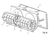
- the front end of the Axialabscheiderotors 8 extends into an inlet head housing 17, which in Fig. 2 is shown in more detail.
- the coarse straw largely freed from the grain during the passage through the axial separation device 6 is ejected at the rear end of the axial separation device 6 and falls over a chute 13 onto the ground.
- the threshing device 2 and the Axialabscheidevoriques 6 thus form a first separation stage or Abscheideeck.
- a second separation stage or purification stage is essentially composed of a fan 14 and a lying in the wind of the blower 14 group of sieve plates 15 which are driven to oscillate in a frame, not shown, and are charged with the pre-cleaned partial flow.
- the grain contained in the pre-cleaned partial stream trickles through the vibrating trays 15 through a downhill first guide bottom 16.
- a screw conveyor 17 is arranged, which promotes the grain to an elevator and through this into a grain tank.
- the Fig. 2a and 2b show a view obliquely from the front and a front view of the inlet head housing 17 of the combine 20.
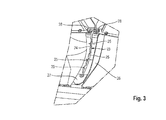
- the inlet head housing 17 each has an over the width of the corresponding Axialabscheiderotors 8 extending flat inlet portion 21 which extends in sections below the feed drum 5. Between the two inlet sections 21 there is a ramp-shaped housing section 22.
- the ramp-shaped housing section 22 has a substantially concave profile, as shown in the side view in FIG Fig. 2b can be seen.
- the separating element 23 extends substantially parallel to the axis of the housing section 22, wherein its profile substantially corresponds to that of the housing section 22.
- the separating element 23 is preferably detachably arranged on the housing portion 22, so that a simple interchangeability, for example as a result of wear is possible.
- the separating element 23 can be screwed to the inlet head housing 17, as in Fig. 3 indicated.
- the separating element 23 is, as in particular from the Fig. 2b and Fig. 3 can be seen, performed blade-shaped.
- the separating element 23 extends perpendicular to the surface of the housing section 22.
- the separating element 23 has a profiled separating edge 24.
- the separating edge 24 has a profile formed from a plurality of at least partially arcuate sections 25.
- the separating edge 24 has a sawtooth-shaped profile or a profile formed from a large number of polygons.
- the height of the profiling decreases in the longitudinal direction of the separating element 23, that is to say in the circumferential direction of the feed drum 5.
- the feed drum 5 has V-shaped baffles 29 in its central region.
- the baffles 29 are in the circumferential direction of Feed drum 5 arranged one behind the other and extending from the lateral surface of the feed roller 5, starting in the radial direction to the outside.
- the guide plates 29 have a profiling 30.
- the shape of this profiling is preferably matched to the shape of the profiling of the separating element 23.
- the separating element 23 cooperates with the rotating feed drum 5.
- the fixed separating element 23 is a type of counter knife for the profiled baffles 29 of the feed drum.
- the profiling 30 may be provided directly on the outer edge of the guide plates 29.
- a profile sheet, which has a corresponding profiling 30 on its outer edge can be detachably fastened to the guide plates 29.
- a base plate 26 is provided, on which the separating element 23 is arranged.
- the base element 26 is releasably connected by means of screws 27 with the housing portion 22 and the inlet head housing 17.
- the separating element 23 is arranged indirectly on the housing portion 22.
- a wedge-shaped projection 26 is mounted on the housing portion 22.
- the immediate arrangement of the separating element 23 on the housing portion 22 is also conceivable.
Landscapes
- Life Sciences & Earth Sciences (AREA)
- Environmental Sciences (AREA)
- Threshing Machine Elements (AREA)
- Outside Dividers And Delivering Mechanisms For Harvesters (AREA)
Abstract
Description
- Die vorliegende Erfindung betrifft ein Einlaufkopfgehäuse für ein Paar Axialabscheiderotoren gemäß dem Oberbegriff des Anspruches 1 sowie einen selbstfahrenden Mähdrescher gemäß Anspruch 10.
- Aus der
WO 2010/086063 A1 sind ein Einlaufkopfgehäuse sowie ein selbstfahrender Mähdrescher der eingangs genannten Art bekannt. Der Mähdrescher umfasst eine ein Paar Abscheiderotoren aufweisende Axialabscheidevorrichtung, welche mit ihrem einen Ende in dem Einlaufkopfgehäuse angeordnet sind. In einem Bereich vor den Öffnungen der Abscheiderotoren befindet sich jeweils ein flächiger Einlaufabschnitt, durch welchen Erntegut dem jeweiligen Abscheiderotor zugeführt wird. Die Zuführung des Erntegutes erfolgt durch eine tangential fördernde Zuführtrommel, die oberhalb des Einlaufabschnittes von den Öffnungen der Abscheiderotoren angeordnet ist. Auf Grund der räumlichen Beabstandung der Abscheiderotoren zueinander weist das Einlaufkopfgehäuse einen rampenförmigen Gehäuseabschnitt auf, dessen Breite im Wesentlichen dem Abstand der beiden Abscheiderotoren zueinander entspricht. Dieser in vertikaler Richtung ansteigende rampenförmige Gehäuseabschnitt weist ein konkaves Profil auf und dient der Unterstützung bei der Auftrennung des zugeführten Erntegutes, um eine gleichmäßige Beschickung der Abscheiderotoren mit Erntegut zu erreichen. Oberhalb des rampenförmigen Gehäuseabschnittes, auf der den Einlaufabschnitten gegenüberliegenden Seite des Einlaufkopfgehäuses ist ein Umlenkelement angeordnet. Das Umlenkelement dient dazu, Erntegut, welches von dem rampenförmigen Gehäuseabschnitt nicht aufgetrennt wird, sondern vielmehr entlang seiner Oberfläche nach oben geschoben wird, in Umfangsrichtung der Zuführtrommel abzulenken. Das von dem Umlenkelement abgelenkte Erntegut gelangt vor oder oben auf die Zuführtrommel, welche dieses mit neu von dem Mähdrescher aufgenommenen Erntegut zusammenführt. Daraufhin wird das Erntegut erneut den Abscheiderotoren zugeführt. - Nachteilig an diesem Umlenkelement ist, dass das Erntegut, welches in Folge von Feuchtigkeit oder Strohlänge durch den rampenförmigen Gehäuseabschnitt zwischen den Abscheiderotoren nicht aufgeteilt werden konnte, erneut der Zuführwalze zugeführt wird, um in zumindest einem weiteren Zuführversuch aufgetrennt zu werden. Diese Vorgehensweise führt zu einer nicht unerheblichen Belastung der Zuführtrommel.
- Es ist daher die Aufgabe der vorliegenden Erfindung, ein Einlaufkopfgehäuse für eine Axialabscheidevorrichtung sowie einen Mähdrescher bereitzustellen, welche sich durch eine verbesserte Auftrennung des Erntegutstromes vor dessen Eintritt in die Axialabscheidevorrichtung auszeichnen.
- Diese Aufgabe wird erfindungsgemäß durch einen Einlaufkopfgehäuse gemäß dem Anspruch 1 sowie durch einen Mähdrescher gemäß dem Anspruch 9 gelöst.
- Gemäß dem Anspruch 1 wird vorgeschlagen, dass auf dem rampenförmigen Gehäuseabschnitt ein sich achsparallel zu diesem erstreckendes, im Wesentlichen klingenförmiges Trennelement angeordnet ist. Das Trennelement wirkt wie eine Schneide auf das Erntegut ein, so dass die Wirkung des rampenförmigen Gehäuseabschnittes beim Auftrennen des Erntegutes, welches gegen das Trennelement gepresst wird, deutlich verbessert wird. Das Trennelement weist eine mit dem Gehäuseabschnitt korrespondierende Kontur auf.
- Das Trennelement kann unmittelbar auf dem rampenförmigen Gehäuseabschnitt angeordnet sein. Dabei kann vorgesehen sein, dass das Trennelement lösbar an dem Gehäuseabschnitt befestigt ist. Hierdurch lässt sich ein einfaches Austauschen beziehungsweise Nachrüsten des rampenförmigen Gehäuseabschnittes mit dem Trennelement bewerkstelligen.
- Vorzugsweise kann auf dem rampenförmigen Gehäuseabschnitt ein keilförmiger Vorsprung angeordnet sein, der der Aufnahme des Trennelementes dient. Das Trennelement kann lösbar an dem Vorsprung befestigt sein. Dabei kann der keilförmige Vorsprung in Längsrichtung eine zunehmende Breite aufweisen. Der zusätzliche Vorsprung auf dem Gehäuseabschnitt unterstützt auf Grund seiner sich in Längsrichtung ändernden Breite das seitliche Ablenken des Aufgetrennten Erntegutes zu den Öffnungen der Abscheiderotoren hin.
- Weiterhin kann sich das Trennelement abschnittsweise über die Breite des Vorsprunges erstrecken. Das Trennelement kann einen Sockel zur Befestigung an dem Vorsprung aufweisen und sich in axialer Richtung gleichförmig oder sprunghaft verjüngend ausgeführt sein, so dass es in einer Art Schneide mündet.
- Insbesondere kann sich das Trennelement zumindest abschnittsweise in Längsrichtung des Gehäuseabschnittes erstrecken.
- Vorzugsweise kann das Trennelement eine profilierte Trennkante aufweisen. Diese Trennkante kann in Abhängigkeit von Erntegutart und Erntebedingungen variieren. Insbesondere auf Grund der Nachrüstbarkeit beziehungsweise damit einhergehend der Auswechselbarkeit kann das Trennelement entsprechend ausgetauscht werden, wenn es die Erntebedingungen erfordern.
- Hierbei kann die Trennkante ein aus einer Vielzahl von zumindest teilweise bogenförmig ausgeführten Abschnitten gebildetes Profil aufweisen. Ein Vorteil dieses Profils besteht darin, dass ein Verklemmen von Stroh zwischen den Abschnitten vermieden werden kann.
- Alternativ kann die Trennkante ein sägezahnförmiges Profil aufweisen. Dieses Profil wirkt aggressiver auf das aufzutrennende Erntegut ein.
- Bevorzugt kann die Trennkante ein aus einer Vielzahl von Polygonen gebildetes Profil aufweisen.
- Vorteilhafterweise kann die Höhe der Profilierung in Längsrichtung des Trennelementes abnehmen. Diese Ausführung trägt dem Umstand Rechnung, dass im unteren Bereich des rampenförmigen Gehäuseabschnittes beziehungsweise des Vorsprunges das Aufkommen an aufzutrennendem Erntegut größer ist, als im oberen Bereich, in welchem die aufzutrennende Erntegutmenge abnimmt.
- Weiterhin betrifft die Erfindung einen selbstfahrenden Mähdrescher, der durch einen Einlaufkopf nach einem der Ansprüche 1 bis 9 gekennzeichnet ist.
- Vorzugsweise kann dem Einlaufkopfgehäuse eine tangential angeordnete Zuführtrommel zugeordnet sein, die in ihrem Mittenbereich in Umfangsrichtung angeordnete V-förmige Leitbleche aufweist, die sich, ausgehend von der Mantelfläche der Zuführtrommel radial nach außen erstrecken. Die Leitbleche können sich in Rotationsrichtung der Zuführtrommel verjüngend ausgebildet sein.
- Vorteilhafterweise kann das jeweilige Leitblech auf seiner Außenkante eine Profilierung aufweisen. Diese Profilierung kann entsprechend der Profilierung des Trennelementes ausgeführt sein. Diese Anordnung ist vorteilhaft, da die Profilierung auf den Außenkanten der Leitbleche der rotierenden Zuführtrommel mit dem als eine Art Gegenmesser fungierenden Trennelement zusammenwirken kann.
- Hierbei kann die Profilierung in die Außenkante des Leitbleches eingearbeitet sein.
- Alternativ kann die Profilierung an einer Außenkante eines Profilbleches vorgesehen sein, welches an dem Leitblech lösbar befestigt ist. Das Profilblech kann als Verschleißbauteil ausgeführt sein, welches bei Bedarf auf Grund der lösbaren Anbringung an dem Leitblech auswechselbar ist. Das Profilblech kann im Wesentlichen mit der Form und den Abmessungen des Leitbleches korrespondieren.
- Die vorliegende Erfindung wird nachstehend anhand eines in den Zeichnungen dargestellten Ausführungsbeispieles näher erläutert.
- Es zeigen:
- Fig. 1
- eine schematische Ansicht eines selbstfahrenden Mähdrescher;
- Fig. 2a
- eine Ansicht eines Einlaufkopfgehäuses des Mähdreschers gemäß
Fig. 1 von schräg vorne; - Fig. 2b
- eine Seitenansicht des Einlaufkopfgehäuses gemäß
Fig. 2a ; - Fig. 3
- eine Detailansicht eines Trennelementes.
- Die Darstellung in
Fig. 1 zeigt einen schematischen Längsschnitt durch den hinteren Bereich eines Mähdreschers 20. In dem nicht dargestellten vorderen Bereich des Mähdreschers 20 wird zu verarbeitendes Erntegut aufgenommen und von einer nur ansatzweise dargestellten Fördereinrichtung 1 einer tangential wirkenden Drescheinrichtung 2 zugeführt. Die Drescheinrichtung 2 umfasst eine Dreschtrommel 3 mit quer zur Fahrrichtung des Mähdreschers 20 orientierter Achse, die auf einem Teil ihres Umfangs von einem Dreschkorb 4 umgeben ist. Ein Teilstrom des von der Drescheinrichtung 2 bearbeiteten Erntegutes gelangt durch Öffnungen in dem Dreschkorb 4 auf einen darunter befindlichen Förderboden 11. - Ein größerer Teilstrom des Erntegutes wird jedoch zwischen Dreschtrommel 3 und Dreschkorb 4 hindurchgeführt und mit Unterstützung durch eine Leittrommel oder Zuführtrommel 5 einer Axialabscheidevorrichtung 6 zugeführt. Die schematisiert dargestellte Axialabscheidevorrichtung 6 ist als zumindest ein zylindrisches, an seinen Enden offenes Gehäuse 7 ausgeführt, in dem über seine gesamte Länge zwei als Förderorgan ausgebildete Axialabscheiderotoren 8 drehantreibbar gelagert ist. Durch die gegenläufige Drehung der Axialabscheiderotoren 8 wird das Erntegut auf einer schraubenlinienförmigen Bahn durch die Axialabscheidevorrichtung 6 gefördert. Von einer Oberseite des Gehäuses 7 in dessen Inneres vorstehende Rippen 9 fördern das Durchkneten des Erntegutes, wenn der äußere Rand der Wendel 18 des Axialabscheiderotors 8 an ihnen vorbeigeführt wird. Der untere Bereich des Gehäuses 7 ist durch Abscheidekörbe 10 gebildet. Das vordere Ende des Axialabscheiderotors 8 erstreckt sich in ein Einlaufkopfgehäuse 17, welches in
Fig. 2 näher dargestellt ist. - Die Bestandteile des von der Axialabscheidevorrichtung 6 abgegebenen Teilstromes, Körner, Spreu und Feinstroh, die durch Öffnungen der Abscheidekörbe 10 aus der Axialabscheidevorrichtung 6 ausgeschieden werden, fallen auf den darunter befindlichen Förderboden 11 beziehungsweise einen Rücklaufboden 12.
- Das während des Durchgangs durch die Axialabscheidevorrichtung 6 weitestgehend vom Korn befreite Grobstroh wird am rückseitigen Ende der Axialabscheidevorrichtung 6 ausgeworfen und fällt über eine Rutsche 13 auf den Boden. Die Drescheinrichtung 2 und die Axialabscheidevorrichtung 6 bilden so eine erste Trennstufe oder Abscheidestufe.
- Eine zweite Trennstufe oder Reinigungsstufe ist im Wesentlichen aufgebaut aus einem Gebläse 14 und einer im Windstrom des Gebläses 14 liegenden Gruppe von Siebböden 15, die in einem nicht dargestellten Rahmengestell oszillierend angetrieben sind, und mit dem vorgereinigten Teilstrom beschickt werden. Das im vorgereinigten Teilstrom enthaltene Korn rieselt durch die schwingenden Siebböden 15 hindurch auf einen abschüssigen ersten Leitboden 16. Am unteren Ende des Leitbodens 16 ist eine Förderschnecke 17 angeordnet, die das Korn zu einem Elevator und durch diesen in einen Korntank fördert.
- Die
Fig. 2a und 2b zeigen eine Ansicht von schräg vorne beziehungsweise eine Seitenansicht des Einlaufkopfgehäuses 17 des Mähdreschers 20. Das Einlaufkopfgehäuse 17 weist jeweils einen sich über die Breite des entsprechenden Axialabscheiderotors 8 erstreckenden flächigen Einlaufabschnitt 21, welcher sich abschnittsweise unterhalb der Zuführtrommel 5 erstreckt. Zwischen den beiden Einlaufabschnitten 21 befindet sich ein rampenförmiger Gehäuseabschnitt 22. Der rampenförmige Gehäuseabschnitt 22 weist ein im Wesentlichen konkaves Profil auf, wie der Seitenansicht inFig. 2b zu entnehmen ist. Auf dem Gehäuseabschnitt 22 ist ein im Wesentlichen klingenförmiges Trennelement 23 angeordnet. Das Trennelement 23 erstreckt sich im Wesentlichen achsparallel zu dem Gehäuseabschnitt 22, wobei dessen Profil im Wesentlichen dem des Gehäuseabschnittes 22 entspricht. Das Trennelement 23 ist vorzugsweise lösbar an dem Gehäuseabschnitt 22 angeordnet, so dass eine einfache Auswechselbarkeit beispielsweise in Folge von Verschleiß möglich ist. Hierzu kann das Trennelement 23 an dem Einlaufkopfgehäuse 17 anschraubbar sein, wie inFig. 3 angedeutet. - Das Trennelement 23 ist, wie insbesondere aus den
Fig. 2b undFig. 3 ersichtlich ist, klingenförmig ausgeführt. Das Trennelement 23 erstreckt sich senkrecht zur Oberfläche des Gehäuseabschnittes 22. Weiterhin weist das Trennelement 23 eine profilierte Trennkante 24 auf. Die Trennkante 24 weist ein aus einer Vielzahl von zumindest teilweise bogenförmig ausgeführten Abschnitten 25 gebildetes Profil auf. Alternativ sind auch Ausführungsformen denkbar, gemäß denen die Trennkante 24 ein sägezahnförmiges Profil oder ein aus einer Vielzahl von Polygonen gebildetes Profil aufweist. Die Höhe der Profilierung nimmt in Längsrichtung des Trennelementes 23, das heißt in Umfangsrichtung der Zuführtrommel 5, ab. Die Zuführtrommel 5 weist in ihrem Mittenbereich V-förmige Leitbleche 29 auf. Die Leitbleche 29 sind in Umfangsrichtung der Zuführtrommel 5 hintereinander angeordnet und erstrecken sich von der Mantelfläche der Zuführwalze 5 ausgehend in radialer Richtung nach außen. An ihren Außenkanten weisen die Leitbleche 29 eine Profilierung 30 auf. Die Form dieser Profilierung ist vorzugsweise auf die Form der Profilierung des Trennelementes 23 abgestimmt. Das Trennelement 23 wirkt mit der rotierenden Zuführtrommel 5 zusammen. Dabei stellt das feststehende Trennelement 23 eine Art Gegenmesser für die profilierten Leitbleche 29 der Zuführtrommel dar. Die Profilierung 30 kann unmittelbar an der Außenkante der Leitbleche 29 vorgesehen sein. Alternativ kann ein Profilblech, welches an seiner Außenkante eine entsprechende Profilierung 30 aufweist, an den Leitblechen 29 lösbar befestigbar sein. - Zur Lösbaren Befestigung an dem rampenförmigen Gehäuseabschnitt 22 ist ein Sockelblech 26 vorgesehen, auf welchem das Trennelement 23 angeordnet ist. Das Sockelelement 26 ist mittels Schrauben 27 mit dem Gehäuseabschnitt 22 beziehungsweise dem Einlaufkopfgehäuse 17 lösbar verbunden. In dem in den Figuren dargestellten Ausführungsbeispiel ist das Trennelement 23 mittelbar an dem Gehäuseabschnitt 22 angeordnet. Hierzu ist auf dem Gehäuseabschnitt 22 ein keilförmiger Vorsprung 26 befestigt. Die unmittelbare Anordnung des Trennelementes 23 auf dem Gehäuseabschnitt 22 ist ebenfalls denkbar.
Bezugszeichenliste 1 Fördereinrichtung 30 Profilierung 2 Drescheinrichtung 3 Dreschtrommel 4 Dreschkorb 5 Zuführtrommel 6 Axialabscheidevorrichtung 7 Gehäuse 8 Axialabscheiderotor 9 Rippen 10 Abscheidekorb 11 Förderboden 12 Rücklaufboden 13 Rutsche 14 Gebläse 15 Siebboden 16 Leitboden 17 Einlaufkopfgehäuse 18 Wendel 19 Förderschnecke 20 Mähdrescher 21 Einlaufabschnitt 22 Rampenförmiger Gehäuseabschnitt 23 Trennelement 24 Trennkante 25 Bogenförmige Abschnitte 26 Keilförmiger Vorsprung 27 Sockelblech 28 Schraube 29 Leitblech
Claims (14)
- Einlaufkopfgehäuse (17) für eine ein Paar Abscheiderotoren (8) aufweisende Axialabscheidevorrichtung (6), die parallel nebeneinander angeordnet mit einem ersten Ende abschnittsweise in das Einlaufkopfgehäuse (17) hineinragen, wobei das Einlaufkopfgehäuse (17) einen sich über die Breite des jeweiligen Abscheiderotors (8) erstreckenden flächigen Einlaufabschnitt (21) aufweist, zwischen denen ein rampenförmiger, im Wesentlichen konkaves Profil aufweisender Gehäuseabschnitt (22) angeordnet ist, welcher die Auftrennung eines Erntegutstromes in zwei den Abscheiderotoren (8) zuzuführende Teilströme zumindest unterstützt, dadurch gekennzeichnet, dass auf dem rampenförmigen Gehäuseabschnitt (22) ein sich im Wesentlichen achsparallel zu diesem erstreckendes, im Wesentlichen klingenförmiges Trennelement (23) angeordnet ist.
- Einlaufkopfgehäuse (17) nach Anspruch 1, dadurch gekennzeichnet, dass auf dem rampenförmigen Gehäuseabschnitt (22) ein keilförmiger Vorsprung (26) angeordnet ist, der der Aufnahme des Trennelementes (23) dient.
- Einlaufkopfgehäuse (17) nach Anspruch 2, dadurch gekennzeichnet, dass sich das Trennelement (23) abschnittsweise über die Breite des Vorsprunges (26) erstreckt.
- Einlaufkopfgehäuse (17) nach einem der Ansprüche 1 bis 3, dadurch gekennzeichnet, dass sich das Trennelement (23) zumindest abschnittsweise in Längsrichtung des Gehäuseabschnittes (22) erstreckt.
- Einlaufkopfgehäuse (17) nach einem der Ansprüche 1 bis 4, dadurch gekennzeichnet, dass das Trennelement (23) eine profilierte Trennkante (24) aufweist.
- Einlaufkopfgehäuse (17) nach Anspruch 5, dadurch gekennzeichnet, dass die Trennkante (24) ein aus einer Vielzahl von zumindest teilweise bogenförmig ausgeführten Abschnitten (25) gebildetes Profil aufweist.
- Einlaufkopfgehäuse (17) nach Anspruch 5, dadurch gekennzeichnet, dass die Trennkante (24) ein sägezahnförmiges Profil aufweist.
- Einlaufkopfgehäuse (17) nach Anspruch 5, dadurch gekennzeichnet, dass die Trennkante (24) ein aus einer Vielzahl von Polygonen gebildetes Profil aufweist.
- Einlaufkopfgehäuse (17) nach einem der Ansprüche 5 bis 8, dadurch gekennzeichnet, dass die Höhe der Profilierung in Längsrichtung des Trennelementes (23) abnimmt.
- Selbstfahrender Mähdrescher (20), gekennzeichnet durch ein Einlaufkopfgehäuse (17) nach einem der Ansprüche 1 bis 9.
- Selbstfahrender Mähdrescher (20) nach Anspruch 10, dadurch gekennzeichnet, dass dem Einlaufkopfgehäuse eine tangential angeordnete Zuführtrommel (5) zugeordnet ist, die in ihrem Mittenbereich in Umfangsrichtung angeordnete V-förmige Leitbleche (29) aufweist, die sich radial nach außen erstrecken.
- Selbstfahrender Mähdrescher (20) nach Anspruch 11, dadurch gekennzeichnet, dass das jeweilige Leitblech (30) an seiner Außenkante eine Profilierung (30) aufweist.
- Selbstfahrender Mähdrescher (20) nach Anspruch 12, dadurch gekennzeichnet, dass die Profilierung (30) in die Außenkante des Leitbleches (29) eingearbeitet ist.
- Selbstfahrender Mähdrescher (20) nach Anspruch 12, dadurch gekennzeichnet, dass die Profilierung (30) an einer Außenkante eines Profilbleches vorgesehen ist, welches an dem Leitblech (29) lösbar befestigt ist.
Applications Claiming Priority (1)
| Application Number | Priority Date | Filing Date | Title |
|---|---|---|---|
| DE102014109702.5A DE102014109702A1 (de) | 2014-07-10 | 2014-07-10 | Einlaufkopfgehäuse |
Publications (2)
| Publication Number | Publication Date |
|---|---|
| EP2965614A1 true EP2965614A1 (de) | 2016-01-13 |
| EP2965614B1 EP2965614B1 (de) | 2018-01-31 |
Family
ID=53005508
Family Applications (1)
| Application Number | Title | Priority Date | Filing Date |
|---|---|---|---|
| EP15165242.7A Active EP2965614B1 (de) | 2014-07-10 | 2015-04-27 | Einlaufkopfgehäuse |
Country Status (3)
| Country | Link |
|---|---|
| US (1) | US9706714B2 (de) |
| EP (1) | EP2965614B1 (de) |
| DE (1) | DE102014109702A1 (de) |
Cited By (5)
| Publication number | Priority date | Publication date | Assignee | Title |
|---|---|---|---|---|
| EP3335543A1 (de) * | 2016-12-16 | 2018-06-20 | CLAAS Selbstfahrende Erntemaschinen GmbH | Austauschbares und/oder verstellbares einlaufsegment für einen mähdrescher mit axialrotor |
| EP3616498A1 (de) * | 2018-08-27 | 2020-03-04 | CLAAS Selbstfahrende Erntemaschinen GmbH | Selbstfahrender mähdrescher mit einem endlos umlaufenden rücklauf-förderband und rücklaufbaugruppe dafür |
| US11382274B2 (en) | 2019-04-29 | 2022-07-12 | Claas Selbstfahrende Erntemaschinen Gmbh | Separation arrangement for a combine harvester |
| EP4338578A1 (de) * | 2022-09-13 | 2024-03-20 | CLAAS Selbstfahrende Erntemaschinen GmbH | Dreschtrommel für eine drescheinrichtung eines mähdreschers sowie mähdrescher |
| EP4338579A1 (de) * | 2022-09-13 | 2024-03-20 | CLAAS Selbstfahrende Erntemaschinen GmbH | Selbstfahrender mähdrescher |
Families Citing this family (9)
| Publication number | Priority date | Publication date | Assignee | Title |
|---|---|---|---|---|
| GB201319215D0 (en) * | 2013-10-31 | 2013-12-18 | Agco As | Grain seperating apparatus in a combine harvester |
| GB201322403D0 (en) * | 2013-12-18 | 2014-02-05 | Agco As | Combine harvester grain cleaning system |
| US9854742B2 (en) * | 2014-12-17 | 2018-01-02 | Agco International Gmbh | Crop processing apparatus in a combine harvester |
| GB201501090D0 (en) * | 2015-01-22 | 2015-03-11 | Agco Int Gmbh | Method of manufacturing a feed beater for an axial-flow crop processor in a combine harvester |
| US20190261571A1 (en) * | 2018-02-27 | 2019-08-29 | Vanderlei Kamphorst | Grain beater accelerator cylinder to harvester |
| WO2019199889A1 (en) | 2018-04-12 | 2019-10-17 | Cnh Industrial America Llc | Concave ramp for an agricultural vehicle |
| US11234373B2 (en) * | 2019-08-13 | 2022-02-01 | Cnh Industrial America Llc | Crop flow guide vanes |
| US12457939B2 (en) * | 2021-11-23 | 2025-11-04 | Deere & Company | Feed accelerator for an agricultural harvester |
| EP4289254A1 (de) * | 2022-06-10 | 2023-12-13 | CNH Industrial Belgium N.V. | Einzugswalze für mähdrescher |
Citations (4)
| Publication number | Priority date | Publication date | Assignee | Title |
|---|---|---|---|---|
| EP0230276A1 (de) * | 1986-01-18 | 1987-07-29 | Claas Ohg | Selbstfahrenden Mähdrescher |
| EP1147701A1 (de) * | 2000-04-19 | 2001-10-24 | CLAAS Selbstfahrende Erntemaschinen GmbH | Selbstfahrender Mähdrescher |
| WO2010086063A1 (en) | 2009-01-27 | 2010-08-05 | Agco A/S | Combine harvesters |
| EP2574231A1 (de) * | 2011-09-30 | 2013-04-03 | CLAAS Selbstfahrende Erntemaschinen GmbH | Mähdrescher |
Family Cites Families (19)
| Publication number | Priority date | Publication date | Assignee | Title |
|---|---|---|---|---|
| US3616800A (en) * | 1969-01-09 | 1971-11-02 | Sperry Rand Corp | Axial flow type combine with a discharge conveyor |
| US3828793A (en) * | 1973-06-29 | 1974-08-13 | Int Harvester Co | Crop feeding mechanism for axial flow combines |
| US3994304A (en) * | 1976-01-06 | 1976-11-30 | Sperry Rand Corporation | Back-flow retarding feed plate for rotary combine |
| US4291709A (en) * | 1980-07-02 | 1981-09-29 | Sperry Corporation | Infeed geometry |
| US4611605A (en) * | 1984-08-29 | 1986-09-16 | Deere & Company | Axial flow rotary separator |
| US4739773A (en) * | 1986-05-09 | 1988-04-26 | Deere & Company | Feeding arrangement for an axial flow rotary separator |
| US4875890A (en) * | 1988-02-29 | 1989-10-24 | Ford New Holland, Inc. | Feed plate assembly for axial flow combine |
| US5342239A (en) * | 1991-05-10 | 1994-08-30 | Deere & Company | Operation parameters for an axial separator |
| US5334093A (en) * | 1991-05-10 | 1994-08-02 | Deere & Company | Detachable covers for an axial separator |
| US5556337A (en) * | 1992-09-28 | 1996-09-17 | Claas Ohg Beschraebkt Haftende Offene | Self-propelling harvester thresher |
| US5344367A (en) * | 1993-03-31 | 1994-09-06 | Deere & Company | Infeed plate for an axial agricultural combine |
| US6129629A (en) * | 1997-05-27 | 2000-10-10 | Claas Selbstfahrende Erntemaschinen Gmbh | Intake zone for axial separator |
| DE10019640A1 (de) * | 2000-04-19 | 2002-04-18 | Claas Selbstfahr Erntemasch | Selbstfahrender Mähdrescher |
| DE10062429A1 (de) * | 2000-12-14 | 2002-07-11 | Claas Selbstfahr Erntemasch | Selbstfahrende Erntemaschine |
| GB0106725D0 (en) * | 2001-03-19 | 2001-05-09 | Claas Selbstfahr Erntemasch | Combine harvester |
| US7070498B2 (en) * | 2003-07-29 | 2006-07-04 | Deere & Company | Frusto-conical drum infeed and threshing region for a combine rotor |
| GB0710995D0 (en) * | 2007-06-08 | 2007-07-18 | Agco Do Brasil Com E Ind Stria | Combines |
| GB0710994D0 (en) * | 2007-06-08 | 2007-07-18 | Agco Do Brasil Com E Ind Stria | Combines |
| US8062109B1 (en) * | 2010-08-27 | 2011-11-22 | Deere & Company | Dust suppressor for combine harvester feederhouse |
-
2014
- 2014-07-10 DE DE102014109702.5A patent/DE102014109702A1/de not_active Withdrawn
-
2015
- 2015-04-27 EP EP15165242.7A patent/EP2965614B1/de active Active
- 2015-07-08 US US14/794,108 patent/US9706714B2/en active Active
Patent Citations (4)
| Publication number | Priority date | Publication date | Assignee | Title |
|---|---|---|---|---|
| EP0230276A1 (de) * | 1986-01-18 | 1987-07-29 | Claas Ohg | Selbstfahrenden Mähdrescher |
| EP1147701A1 (de) * | 2000-04-19 | 2001-10-24 | CLAAS Selbstfahrende Erntemaschinen GmbH | Selbstfahrender Mähdrescher |
| WO2010086063A1 (en) | 2009-01-27 | 2010-08-05 | Agco A/S | Combine harvesters |
| EP2574231A1 (de) * | 2011-09-30 | 2013-04-03 | CLAAS Selbstfahrende Erntemaschinen GmbH | Mähdrescher |
Cited By (5)
| Publication number | Priority date | Publication date | Assignee | Title |
|---|---|---|---|---|
| EP3335543A1 (de) * | 2016-12-16 | 2018-06-20 | CLAAS Selbstfahrende Erntemaschinen GmbH | Austauschbares und/oder verstellbares einlaufsegment für einen mähdrescher mit axialrotor |
| EP3616498A1 (de) * | 2018-08-27 | 2020-03-04 | CLAAS Selbstfahrende Erntemaschinen GmbH | Selbstfahrender mähdrescher mit einem endlos umlaufenden rücklauf-förderband und rücklaufbaugruppe dafür |
| US11382274B2 (en) | 2019-04-29 | 2022-07-12 | Claas Selbstfahrende Erntemaschinen Gmbh | Separation arrangement for a combine harvester |
| EP4338578A1 (de) * | 2022-09-13 | 2024-03-20 | CLAAS Selbstfahrende Erntemaschinen GmbH | Dreschtrommel für eine drescheinrichtung eines mähdreschers sowie mähdrescher |
| EP4338579A1 (de) * | 2022-09-13 | 2024-03-20 | CLAAS Selbstfahrende Erntemaschinen GmbH | Selbstfahrender mähdrescher |
Also Published As
| Publication number | Publication date |
|---|---|
| DE102014109702A1 (de) | 2016-01-14 |
| EP2965614B1 (de) | 2018-01-31 |
| US9706714B2 (en) | 2017-07-18 |
| US20160007536A1 (en) | 2016-01-14 |
Similar Documents
| Publication | Publication Date | Title |
|---|---|---|
| EP2965614B1 (de) | Einlaufkopfgehäuse | |
| DE2948272C2 (de) | ||
| EP2752108B1 (de) | Dreschvorrichtung | |
| EP0522268B1 (de) | Axialabscheider | |
| EP0522267B1 (de) | Axialabscheider | |
| DE2725588C2 (de) | ||
| EP2594126B1 (de) | Abscheidekorb | |
| EP0521280B1 (de) | Axialabscheider | |
| DE2462568A1 (de) | Dreschmaschine, insbesondere maehdrescher | |
| EP1894465A1 (de) | Erntegutbearbeitungseinheit mit wählbaren Leitschienen unterschiedlicher Steigung | |
| DE2943839A1 (de) | Maehdrescher mit axialer durchlaufrichtung | |
| EP2011384B1 (de) | Erntegutbearbeitungseinheit mit durchsatzabhängiger Umlaufzahl | |
| EP3208466A1 (de) | Reinigungsgebläse mit kunststoffgehäuse sowie verwendung eines rotationsformverfahrens zur herstellung eines einteiligen gehäuses | |
| DE102016117598A1 (de) | Abscheidekorb für einen Mähdrescher | |
| EP3797577B1 (de) | Mähdrescher mit restkornsensor | |
| EP3753393B1 (de) | Selbstfahrender mähdrescher | |
| EP3501258A1 (de) | Mähdrescher | |
| EP3369301A1 (de) | Landwirtschaftliche erntemaschine | |
| EP2382857B1 (de) | Drescheinrichtung für Mähdrescher | |
| EP3150058B1 (de) | Mähdrescher | |
| EP3763198B1 (de) | Dreschtrommel einer dreschvorrichtung für einen mähdrescher | |
| DE102011088543B4 (de) | Mähdrescher mit einer zwischen der Drescheinrichtung und der Reinigung angeordneten Nachdrescheinrichtung | |
| WO2022129548A1 (de) | Trennvorrichtung, mähdrescher mit einer trennvorrichtung und verfahren zur separierung von beikrautsamen und verlustfrüchten aus dem reinigungsabgang einer erntemaschine | |
| EP2997813B1 (de) | Mähdrescher | |
| DE102014114025A1 (de) | Mähdrescher mit einer tangential angeordneten Drescheinrichtung |
Legal Events
| Date | Code | Title | Description |
|---|---|---|---|
| PUAI | Public reference made under article 153(3) epc to a published international application that has entered the european phase |
Free format text: ORIGINAL CODE: 0009012 |
|
| AK | Designated contracting states |
Kind code of ref document: A1 Designated state(s): AL AT BE BG CH CY CZ DE DK EE ES FI FR GB GR HR HU IE IS IT LI LT LU LV MC MK MT NL NO PL PT RO RS SE SI SK SM TR |
|
| AX | Request for extension of the european patent |
Extension state: BA ME |
|
| 17P | Request for examination filed |
Effective date: 20160713 |
|
| RBV | Designated contracting states (corrected) |
Designated state(s): AL AT BE BG CH CY CZ DE DK EE ES FI FR GB GR HR HU IE IS IT LI LT LU LV MC MK MT NL NO PL PT RO RS SE SI SK SM TR |
|
| RAP1 | Party data changed (applicant data changed or rights of an application transferred) |
Owner name: CLAAS SELBSTFAHRENDE ERNTEMASCHINEN GMBH |
|
| STAA | Information on the status of an ep patent application or granted ep patent |
Free format text: STATUS: EXAMINATION IS IN PROGRESS |
|
| 17Q | First examination report despatched |
Effective date: 20170203 |
|
| GRAP | Despatch of communication of intention to grant a patent |
Free format text: ORIGINAL CODE: EPIDOSNIGR1 |
|
| STAA | Information on the status of an ep patent application or granted ep patent |
Free format text: STATUS: GRANT OF PATENT IS INTENDED |
|
| INTG | Intention to grant announced |
Effective date: 20171023 |
|
| GRAS | Grant fee paid |
Free format text: ORIGINAL CODE: EPIDOSNIGR3 |
|
| GRAA | (expected) grant |
Free format text: ORIGINAL CODE: 0009210 |
|
| STAA | Information on the status of an ep patent application or granted ep patent |
Free format text: STATUS: THE PATENT HAS BEEN GRANTED |
|
| AK | Designated contracting states |
Kind code of ref document: B1 Designated state(s): AL AT BE BG CH CY CZ DE DK EE ES FI FR GB GR HR HU IE IS IT LI LT LU LV MC MK MT NL NO PL PT RO RS SE SI SK SM TR |
|
| REG | Reference to a national code |
Ref country code: GB Ref legal event code: FG4D Free format text: NOT ENGLISH Ref country code: CH Ref legal event code: EP |
|
| REG | Reference to a national code |
Ref country code: AT Ref legal event code: REF Ref document number: 966490 Country of ref document: AT Kind code of ref document: T Effective date: 20180215 |
|
| REG | Reference to a national code |
Ref country code: IE Ref legal event code: FG4D Free format text: LANGUAGE OF EP DOCUMENT: GERMAN |
|
| REG | Reference to a national code |
Ref country code: DE Ref legal event code: R096 Ref document number: 502015002937 Country of ref document: DE |
|
| REG | Reference to a national code |
Ref country code: FR Ref legal event code: PLFP Year of fee payment: 4 |
|
| REG | Reference to a national code |
Ref country code: NL Ref legal event code: MP Effective date: 20180131 |
|
| REG | Reference to a national code |
Ref country code: LT Ref legal event code: MG4D |
|
| PG25 | Lapsed in a contracting state [announced via postgrant information from national office to epo] |
Ref country code: FI Free format text: LAPSE BECAUSE OF FAILURE TO SUBMIT A TRANSLATION OF THE DESCRIPTION OR TO PAY THE FEE WITHIN THE PRESCRIBED TIME-LIMIT Effective date: 20180131 Ref country code: HR Free format text: LAPSE BECAUSE OF FAILURE TO SUBMIT A TRANSLATION OF THE DESCRIPTION OR TO PAY THE FEE WITHIN THE PRESCRIBED TIME-LIMIT Effective date: 20180131 Ref country code: NL Free format text: LAPSE BECAUSE OF FAILURE TO SUBMIT A TRANSLATION OF THE DESCRIPTION OR TO PAY THE FEE WITHIN THE PRESCRIBED TIME-LIMIT Effective date: 20180131 Ref country code: NO Free format text: LAPSE BECAUSE OF FAILURE TO SUBMIT A TRANSLATION OF THE DESCRIPTION OR TO PAY THE FEE WITHIN THE PRESCRIBED TIME-LIMIT Effective date: 20180430 Ref country code: LT Free format text: LAPSE BECAUSE OF FAILURE TO SUBMIT A TRANSLATION OF THE DESCRIPTION OR TO PAY THE FEE WITHIN THE PRESCRIBED TIME-LIMIT Effective date: 20180131 Ref country code: ES Free format text: LAPSE BECAUSE OF FAILURE TO SUBMIT A TRANSLATION OF THE DESCRIPTION OR TO PAY THE FEE WITHIN THE PRESCRIBED TIME-LIMIT Effective date: 20180131 |
|
| PG25 | Lapsed in a contracting state [announced via postgrant information from national office to epo] |
Ref country code: BG Free format text: LAPSE BECAUSE OF FAILURE TO SUBMIT A TRANSLATION OF THE DESCRIPTION OR TO PAY THE FEE WITHIN THE PRESCRIBED TIME-LIMIT Effective date: 20180430 Ref country code: SE Free format text: LAPSE BECAUSE OF FAILURE TO SUBMIT A TRANSLATION OF THE DESCRIPTION OR TO PAY THE FEE WITHIN THE PRESCRIBED TIME-LIMIT Effective date: 20180131 Ref country code: IS Free format text: LAPSE BECAUSE OF FAILURE TO SUBMIT A TRANSLATION OF THE DESCRIPTION OR TO PAY THE FEE WITHIN THE PRESCRIBED TIME-LIMIT Effective date: 20180531 Ref country code: LV Free format text: LAPSE BECAUSE OF FAILURE TO SUBMIT A TRANSLATION OF THE DESCRIPTION OR TO PAY THE FEE WITHIN THE PRESCRIBED TIME-LIMIT Effective date: 20180131 Ref country code: GR Free format text: LAPSE BECAUSE OF FAILURE TO SUBMIT A TRANSLATION OF THE DESCRIPTION OR TO PAY THE FEE WITHIN THE PRESCRIBED TIME-LIMIT Effective date: 20180501 Ref country code: PL Free format text: LAPSE BECAUSE OF FAILURE TO SUBMIT A TRANSLATION OF THE DESCRIPTION OR TO PAY THE FEE WITHIN THE PRESCRIBED TIME-LIMIT Effective date: 20180131 Ref country code: RS Free format text: LAPSE BECAUSE OF FAILURE TO SUBMIT A TRANSLATION OF THE DESCRIPTION OR TO PAY THE FEE WITHIN THE PRESCRIBED TIME-LIMIT Effective date: 20180131 |
|
| PG25 | Lapsed in a contracting state [announced via postgrant information from national office to epo] |
Ref country code: MT Free format text: LAPSE BECAUSE OF FAILURE TO SUBMIT A TRANSLATION OF THE DESCRIPTION OR TO PAY THE FEE WITHIN THE PRESCRIBED TIME-LIMIT Effective date: 20180131 |
|
| PG25 | Lapsed in a contracting state [announced via postgrant information from national office to epo] |
Ref country code: RO Free format text: LAPSE BECAUSE OF FAILURE TO SUBMIT A TRANSLATION OF THE DESCRIPTION OR TO PAY THE FEE WITHIN THE PRESCRIBED TIME-LIMIT Effective date: 20180131 Ref country code: EE Free format text: LAPSE BECAUSE OF FAILURE TO SUBMIT A TRANSLATION OF THE DESCRIPTION OR TO PAY THE FEE WITHIN THE PRESCRIBED TIME-LIMIT Effective date: 20180131 Ref country code: AL Free format text: LAPSE BECAUSE OF FAILURE TO SUBMIT A TRANSLATION OF THE DESCRIPTION OR TO PAY THE FEE WITHIN THE PRESCRIBED TIME-LIMIT Effective date: 20180131 |
|
| REG | Reference to a national code |
Ref country code: DE Ref legal event code: R097 Ref document number: 502015002937 Country of ref document: DE |
|
| PG25 | Lapsed in a contracting state [announced via postgrant information from national office to epo] |
Ref country code: DK Free format text: LAPSE BECAUSE OF FAILURE TO SUBMIT A TRANSLATION OF THE DESCRIPTION OR TO PAY THE FEE WITHIN THE PRESCRIBED TIME-LIMIT Effective date: 20180131 Ref country code: SK Free format text: LAPSE BECAUSE OF FAILURE TO SUBMIT A TRANSLATION OF THE DESCRIPTION OR TO PAY THE FEE WITHIN THE PRESCRIBED TIME-LIMIT Effective date: 20180131 Ref country code: MC Free format text: LAPSE BECAUSE OF FAILURE TO SUBMIT A TRANSLATION OF THE DESCRIPTION OR TO PAY THE FEE WITHIN THE PRESCRIBED TIME-LIMIT Effective date: 20180131 Ref country code: CZ Free format text: LAPSE BECAUSE OF FAILURE TO SUBMIT A TRANSLATION OF THE DESCRIPTION OR TO PAY THE FEE WITHIN THE PRESCRIBED TIME-LIMIT Effective date: 20180131 Ref country code: SM Free format text: LAPSE BECAUSE OF FAILURE TO SUBMIT A TRANSLATION OF THE DESCRIPTION OR TO PAY THE FEE WITHIN THE PRESCRIBED TIME-LIMIT Effective date: 20180131 |
|
| REG | Reference to a national code |
Ref country code: CH Ref legal event code: PL |
|
| PLBE | No opposition filed within time limit |
Free format text: ORIGINAL CODE: 0009261 |
|
| STAA | Information on the status of an ep patent application or granted ep patent |
Free format text: STATUS: NO OPPOSITION FILED WITHIN TIME LIMIT |
|
| 26N | No opposition filed |
Effective date: 20181102 |
|
| REG | Reference to a national code |
Ref country code: IE Ref legal event code: MM4A |
|
| PG25 | Lapsed in a contracting state [announced via postgrant information from national office to epo] |
Ref country code: LU Free format text: LAPSE BECAUSE OF NON-PAYMENT OF DUE FEES Effective date: 20180427 |
|
| PG25 | Lapsed in a contracting state [announced via postgrant information from national office to epo] |
Ref country code: LI Free format text: LAPSE BECAUSE OF NON-PAYMENT OF DUE FEES Effective date: 20180430 Ref country code: CH Free format text: LAPSE BECAUSE OF NON-PAYMENT OF DUE FEES Effective date: 20180430 Ref country code: SI Free format text: LAPSE BECAUSE OF FAILURE TO SUBMIT A TRANSLATION OF THE DESCRIPTION OR TO PAY THE FEE WITHIN THE PRESCRIBED TIME-LIMIT Effective date: 20180131 |
|
| PG25 | Lapsed in a contracting state [announced via postgrant information from national office to epo] |
Ref country code: IE Free format text: LAPSE BECAUSE OF NON-PAYMENT OF DUE FEES Effective date: 20180427 |
|
| GBPC | Gb: european patent ceased through non-payment of renewal fee |
Effective date: 20190427 |
|
| PG25 | Lapsed in a contracting state [announced via postgrant information from national office to epo] |
Ref country code: GB Free format text: LAPSE BECAUSE OF NON-PAYMENT OF DUE FEES Effective date: 20190427 |
|
| PG25 | Lapsed in a contracting state [announced via postgrant information from national office to epo] |
Ref country code: TR Free format text: LAPSE BECAUSE OF FAILURE TO SUBMIT A TRANSLATION OF THE DESCRIPTION OR TO PAY THE FEE WITHIN THE PRESCRIBED TIME-LIMIT Effective date: 20180131 |
|
| PG25 | Lapsed in a contracting state [announced via postgrant information from national office to epo] |
Ref country code: PT Free format text: LAPSE BECAUSE OF FAILURE TO SUBMIT A TRANSLATION OF THE DESCRIPTION OR TO PAY THE FEE WITHIN THE PRESCRIBED TIME-LIMIT Effective date: 20180131 |
|
| PG25 | Lapsed in a contracting state [announced via postgrant information from national office to epo] |
Ref country code: HU Free format text: LAPSE BECAUSE OF FAILURE TO SUBMIT A TRANSLATION OF THE DESCRIPTION OR TO PAY THE FEE WITHIN THE PRESCRIBED TIME-LIMIT; INVALID AB INITIO Effective date: 20150427 Ref country code: CY Free format text: LAPSE BECAUSE OF FAILURE TO SUBMIT A TRANSLATION OF THE DESCRIPTION OR TO PAY THE FEE WITHIN THE PRESCRIBED TIME-LIMIT Effective date: 20180131 Ref country code: MK Free format text: LAPSE BECAUSE OF NON-PAYMENT OF DUE FEES Effective date: 20180131 |
|
| REG | Reference to a national code |
Ref country code: AT Ref legal event code: MM01 Ref document number: 966490 Country of ref document: AT Kind code of ref document: T Effective date: 20200427 |
|
| PG25 | Lapsed in a contracting state [announced via postgrant information from national office to epo] |
Ref country code: AT Free format text: LAPSE BECAUSE OF NON-PAYMENT OF DUE FEES Effective date: 20200427 |
|
| P01 | Opt-out of the competence of the unified patent court (upc) registered |
Effective date: 20230516 |
|
| PGFP | Annual fee paid to national office [announced via postgrant information from national office to epo] |
Ref country code: DE Payment date: 20250422 Year of fee payment: 11 |
|
| PGFP | Annual fee paid to national office [announced via postgrant information from national office to epo] |
Ref country code: BE Payment date: 20250418 Year of fee payment: 11 Ref country code: IT Payment date: 20250424 Year of fee payment: 11 |
|
| PGFP | Annual fee paid to national office [announced via postgrant information from national office to epo] |
Ref country code: FR Payment date: 20250425 Year of fee payment: 11 |