EP2965614A1 - Boîtier de collecteur d'entrée - Google Patents
Boîtier de collecteur d'entrée Download PDFInfo
- Publication number
- EP2965614A1 EP2965614A1 EP15165242.7A EP15165242A EP2965614A1 EP 2965614 A1 EP2965614 A1 EP 2965614A1 EP 15165242 A EP15165242 A EP 15165242A EP 2965614 A1 EP2965614 A1 EP 2965614A1
- Authority
- EP
- European Patent Office
- Prior art keywords
- head housing
- inlet head
- shaped
- separating element
- housing
- Prior art date
- Legal status (The legal status is an assumption and is not a legal conclusion. Google has not performed a legal analysis and makes no representation as to the accuracy of the status listed.)
- Granted
Links
Images


Classifications
-
- A—HUMAN NECESSITIES
- A01—AGRICULTURE; FORESTRY; ANIMAL HUSBANDRY; HUNTING; TRAPPING; FISHING
- A01F—PROCESSING OF HARVESTED PRODUCE; HAY OR STRAW PRESSES; DEVICES FOR STORING AGRICULTURAL OR HORTICULTURAL PRODUCE
- A01F12/00—Parts or details of threshing apparatus
- A01F12/30—Straw separators, i.e. straw walkers, for separating residual grain from the straw
- A01F12/395—Conical or cylindrical straw separators with internal working surface
-
- A—HUMAN NECESSITIES
- A01—AGRICULTURE; FORESTRY; ANIMAL HUSBANDRY; HUNTING; TRAPPING; FISHING
- A01D—HARVESTING; MOWING
- A01D41/00—Combines, i.e. harvesters or mowers combined with threshing devices
- A01D41/12—Details of combines
-
- A—HUMAN NECESSITIES
- A01—AGRICULTURE; FORESTRY; ANIMAL HUSBANDRY; HUNTING; TRAPPING; FISHING
- A01F—PROCESSING OF HARVESTED PRODUCE; HAY OR STRAW PRESSES; DEVICES FOR STORING AGRICULTURAL OR HORTICULTURAL PRODUCE
- A01F7/00—Threshing apparatus
- A01F7/02—Threshing apparatus with rotating tools
- A01F7/06—Threshing apparatus with rotating tools with axles in line with the feeding direction ; Axial threshing machines
- A01F7/067—Threshing apparatus with rotating tools with axles in line with the feeding direction ; Axial threshing machines with material-flow influencing means
Definitions
- the present invention relates to an inlet head housing for a pair of Axialabscheiderotoren according to the preamble of claim 1 and a self-propelled combine harvester according to claim 10.
- the combine harvester comprises an axial separation device having a pair of separator motors, which are arranged with their one end in the inlet head housing. In a region in front of the openings of the separator motors is in each case a flat inlet section through which crop is fed to the respective separator rotor.
- the supply of the crop is carried out by a tangentially conveying feed drum, which is arranged above the inlet section of the openings of the separator motors.
- the inlet head housing has a ramp-shaped housing section whose width substantially corresponds to the distance between the two separator motors to one another.
- This ramp-shaped housing section rising in the vertical direction has a concave profile and serves to assist in the separation of the fed crop to achieve a uniform feed of the separation motors with crop.
- a deflecting element is arranged above the ramp-shaped housing section, on the side opposite the inlet sections of the inlet head housing.
- the deflecting element serves to deflect crop material, which is not separated from the ramp-shaped housing section, but rather is pushed upwards along its surface, in the circumferential direction of the feed drum. The deflected by the deflecting crop passes before or on top of the feed drum, which merges this with newly picked up by the combine crop. Then the crop is fed again to the separator motors.
- an axially parallel to this extending, substantially blade-shaped separating element is arranged on the ramp-shaped housing portion.
- the separating element acts as a cutting edge on the crop, so that the effect of the ramp-shaped housing section when separating the crop, which is pressed against the separating element, is significantly improved.
- the separating element has a contour corresponding to the housing section.
- the separating element can be arranged directly on the ramp-shaped housing section. It can be provided that the separating element is releasably secured to the housing portion. This makes it easy to replace or retrofit the ramp-shaped housing section with the separating element accomplish.
- a wedge-shaped projection which serves to receive the separating element, can be arranged on the ramp-shaped housing section.
- the partition may be releasably attached to the projection.
- the wedge-shaped projection may have an increasing width in the longitudinal direction. The additional projection on the housing section, due to its longitudinally varying width, assists lateral deflection of the separated crop to the openings of the separator motors.
- the separating element may extend in sections over the width of the projection.
- the separating element may have a base for attachment to the projection and be designed to taper uniformly or suddenly in the axial direction, so that it opens into a kind of cutting edge.
- the separating element may extend at least in sections in the longitudinal direction of the housing section.
- the separating element may have a profiled separating edge.
- This separating edge may vary depending on the crop type and harvesting conditions.
- the separating element can be replaced accordingly, if required by the harvesting conditions.
- the separating edge may have a profile formed from a large number of sections that are at least partially curved.
- the separating edge may have a sawtooth-shaped profile. This profile has a more aggressive effect on the crop to be cut.
- the separating edge may preferably have a profile formed from a plurality of polygons.
- the height of the profiling in the longitudinal direction of the separating element decrease.
- This embodiment takes into account the fact that in the lower region of the ramp-shaped housing section or the projection, the amount of crop to be separated is greater than in the upper region in which the crop quantity to be separated decreases.
- the invention relates to a self-propelled combine harvester, which is characterized by an inlet head according to one of claims 1 to 9.
- the inlet head housing may be associated with a tangentially arranged feed drum having in its center region arranged in the circumferential direction V-shaped guide plates, which, starting from the lateral surface of the feed drum extend radially outward.
- the baffles may be tapered in the direction of rotation of the feed drum.
- the respective baffle may have a profiling on its outer edge.
- This profiling can be carried out according to the profiling of the separating element.
- This arrangement is advantageous because the profiling on the outer edges of the baffles of the rotating feed drum can cooperate with acting as a kind of counter knife separating element.
- the profiling can be incorporated into the outer edge of the baffle.
- the profiling may be provided on an outer edge of a profile sheet, which is releasably secured to the baffle.
- the profile sheet may be designed as a wear component, which is replaceable if necessary due to the detachable attachment to the baffle.
- the profiled sheet may substantially correspond to the shape and dimensions of the baffle.
- FIG. 1 shows a schematic longitudinal section through the rear portion of a combine harvester 20.
- the threshing device 2 comprises a threshing drum 3 with an axis oriented transversely to the direction of travel of the combine harvester 20, which axis is surrounded by a threshing basket 4 over part of its circumference.
- a partial flow of the crop from the threshing 2 processed passes through openings in the concave 4 on an underlying conveyor bottom eleventh
- Axialabscheidevorraum 6 is designed as at least one cylindrical, open at its ends housing 7, in which over its entire length designed as a conveying member Axialabscheiderotoren 8 is rotatably mounted. Due to the opposite rotation of the Axialabscheiderotoren 8, the crop is conveyed on a helical path through the Axialabscheidevorraum 6.
- the housing 7 From a top of the housing 7 in its interior projecting ribs 9 promote the kneading of the crop, when the outer edge of the coil 18 of the Axialabscheiderotors 8 is guided past them.
- the lower portion of the housing 7 is formed by separating baskets 10.
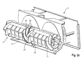
- the front end of the Axialabscheiderotors 8 extends into an inlet head housing 17, which in Fig. 2 is shown in more detail.
- the coarse straw largely freed from the grain during the passage through the axial separation device 6 is ejected at the rear end of the axial separation device 6 and falls over a chute 13 onto the ground.
- the threshing device 2 and the Axialabscheidevoriques 6 thus form a first separation stage or Abscheideeck.
- a second separation stage or purification stage is essentially composed of a fan 14 and a lying in the wind of the blower 14 group of sieve plates 15 which are driven to oscillate in a frame, not shown, and are charged with the pre-cleaned partial flow.
- the grain contained in the pre-cleaned partial stream trickles through the vibrating trays 15 through a downhill first guide bottom 16.
- a screw conveyor 17 is arranged, which promotes the grain to an elevator and through this into a grain tank.
- the Fig. 2a and 2b show a view obliquely from the front and a front view of the inlet head housing 17 of the combine 20.
- the inlet head housing 17 each has an over the width of the corresponding Axialabscheiderotors 8 extending flat inlet portion 21 which extends in sections below the feed drum 5. Between the two inlet sections 21 there is a ramp-shaped housing section 22.
- the ramp-shaped housing section 22 has a substantially concave profile, as shown in the side view in FIG Fig. 2b can be seen.
- the separating element 23 extends substantially parallel to the axis of the housing section 22, wherein its profile substantially corresponds to that of the housing section 22.
- the separating element 23 is preferably detachably arranged on the housing portion 22, so that a simple interchangeability, for example as a result of wear is possible.
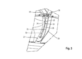
- the separating element 23 can be screwed to the inlet head housing 17, as in Fig. 3 indicated.
- the separating element 23 is, as in particular from the Fig. 2b and Fig. 3 can be seen, performed blade-shaped.
- the separating element 23 extends perpendicular to the surface of the housing section 22.
- the separating element 23 has a profiled separating edge 24.
- the separating edge 24 has a profile formed from a plurality of at least partially arcuate sections 25.
- the separating edge 24 has a sawtooth-shaped profile or a profile formed from a large number of polygons.
- the height of the profiling decreases in the longitudinal direction of the separating element 23, that is to say in the circumferential direction of the feed drum 5.
- the feed drum 5 has V-shaped baffles 29 in its central region.
- the baffles 29 are in the circumferential direction of Feed drum 5 arranged one behind the other and extending from the lateral surface of the feed roller 5, starting in the radial direction to the outside.
- the guide plates 29 have a profiling 30.
- the shape of this profiling is preferably matched to the shape of the profiling of the separating element 23.
- the separating element 23 cooperates with the rotating feed drum 5.
- the fixed separating element 23 is a type of counter knife for the profiled baffles 29 of the feed drum.
- the profiling 30 may be provided directly on the outer edge of the guide plates 29.
- a profile sheet, which has a corresponding profiling 30 on its outer edge can be detachably fastened to the guide plates 29.
- a base plate 26 is provided, on which the separating element 23 is arranged.
- the base element 26 is releasably connected by means of screws 27 with the housing portion 22 and the inlet head housing 17.
- the separating element 23 is arranged indirectly on the housing portion 22.
- a wedge-shaped projection 26 is mounted on the housing portion 22.
- the immediate arrangement of the separating element 23 on the housing portion 22 is also conceivable.
Applications Claiming Priority (1)
| Application Number | Priority Date | Filing Date | Title |
|---|---|---|---|
| DE102014109702.5A DE102014109702A1 (de) | 2014-07-10 | 2014-07-10 | Einlaufkopfgehäuse |
Publications (2)
| Publication Number | Publication Date |
|---|---|
| EP2965614A1 true EP2965614A1 (fr) | 2016-01-13 |
| EP2965614B1 EP2965614B1 (fr) | 2018-01-31 |
Family
ID=53005508
Family Applications (1)
| Application Number | Title | Priority Date | Filing Date |
|---|---|---|---|
| EP15165242.7A Active EP2965614B1 (fr) | 2014-07-10 | 2015-04-27 | Boîtier de collecteur d'entrée |
Country Status (3)
| Country | Link |
|---|---|
| US (1) | US9706714B2 (fr) |
| EP (1) | EP2965614B1 (fr) |
| DE (1) | DE102014109702A1 (fr) |
Cited By (5)
| Publication number | Priority date | Publication date | Assignee | Title |
|---|---|---|---|---|
| EP3335543A1 (fr) * | 2016-12-16 | 2018-06-20 | CLAAS Selbstfahrende Erntemaschinen GmbH | Segment d'entrée échangeable et/ou ajustable pour une moissonneuse-batteuse à rotor axial |
| EP3616498A1 (fr) * | 2018-08-27 | 2020-03-04 | CLAAS Selbstfahrende Erntemaschinen GmbH | Moissonneuse-batteuse automotrice dotée d'une bande transporteuse de retour sans fin et module de retour correspondant |
| US11382274B2 (en) | 2019-04-29 | 2022-07-12 | Claas Selbstfahrende Erntemaschinen Gmbh | Separation arrangement for a combine harvester |
| EP4338578A1 (fr) * | 2022-09-13 | 2024-03-20 | CLAAS Selbstfahrende Erntemaschinen GmbH | Tambour batteur pour un dispositif batteur d'une moissonneuse-batteuse ainsi que moissonneuse-batteuse |
| EP4338579A1 (fr) * | 2022-09-13 | 2024-03-20 | CLAAS Selbstfahrende Erntemaschinen GmbH | Moissonneuse-batteuse automotrice |
Families Citing this family (8)
| Publication number | Priority date | Publication date | Assignee | Title |
|---|---|---|---|---|
| GB201319215D0 (en) * | 2013-10-31 | 2013-12-18 | Agco As | Grain seperating apparatus in a combine harvester |
| GB201322403D0 (en) * | 2013-12-18 | 2014-02-05 | Agco As | Combine harvester grain cleaning system |
| EP3232767B1 (fr) * | 2014-12-17 | 2021-02-24 | AGCO International GmbH | Appareil de traitement de récolte dans une moissonneuse-batteuse |
| GB201501090D0 (en) * | 2015-01-22 | 2015-03-11 | Agco Int Gmbh | Method of manufacturing a feed beater for an axial-flow crop processor in a combine harvester |
| US20190261571A1 (en) * | 2018-02-27 | 2019-08-29 | Vanderlei Kamphorst | Grain beater accelerator cylinder to harvester |
| US11116137B2 (en) | 2018-04-12 | 2021-09-14 | Cnh Industrial America Llc | Concave ramp for an agricultural vehicle |
| US11234373B2 (en) * | 2019-08-13 | 2022-02-01 | Cnh Industrial America Llc | Crop flow guide vanes |
| EP4289254A1 (fr) * | 2022-06-10 | 2023-12-13 | CNH Industrial Belgium N.V. | Rouleau d'alimentation pour moissonneuse-batteuse |
Citations (4)
| Publication number | Priority date | Publication date | Assignee | Title |
|---|---|---|---|---|
| EP0230276A1 (fr) * | 1986-01-18 | 1987-07-29 | Claas Ohg | Moissonneuse-batteuse automotrice |
| EP1147701A1 (fr) * | 2000-04-19 | 2001-10-24 | CLAAS Selbstfahrende Erntemaschinen GmbH | Moissonneuse-batteuse automotrice |
| WO2010086063A1 (fr) | 2009-01-27 | 2010-08-05 | Agco A/S | Moissonneuse-batteuse |
| EP2574231A1 (fr) * | 2011-09-30 | 2013-04-03 | CLAAS Selbstfahrende Erntemaschinen GmbH | Moissonneuse-batteuse |
Family Cites Families (19)
| Publication number | Priority date | Publication date | Assignee | Title |
|---|---|---|---|---|
| US3645270A (en) * | 1969-01-09 | 1972-02-29 | Sperry Rand Corp | Axial flow threshing and separating unit creating an airflow along the grain pan |
| US3828793A (en) * | 1973-06-29 | 1974-08-13 | Int Harvester Co | Crop feeding mechanism for axial flow combines |
| US3994304A (en) * | 1976-01-06 | 1976-11-30 | Sperry Rand Corporation | Back-flow retarding feed plate for rotary combine |
| US4291709A (en) * | 1980-07-02 | 1981-09-29 | Sperry Corporation | Infeed geometry |
| US4611605A (en) * | 1984-08-29 | 1986-09-16 | Deere & Company | Axial flow rotary separator |
| US4739773A (en) * | 1986-05-09 | 1988-04-26 | Deere & Company | Feeding arrangement for an axial flow rotary separator |
| US4875890A (en) * | 1988-02-29 | 1989-10-24 | Ford New Holland, Inc. | Feed plate assembly for axial flow combine |
| US5334093A (en) * | 1991-05-10 | 1994-08-02 | Deere & Company | Detachable covers for an axial separator |
| US5342239A (en) * | 1991-05-10 | 1994-08-30 | Deere & Company | Operation parameters for an axial separator |
| US5556337A (en) * | 1992-09-28 | 1996-09-17 | Claas Ohg Beschraebkt Haftende Offene | Self-propelling harvester thresher |
| US5344367A (en) * | 1993-03-31 | 1994-09-06 | Deere & Company | Infeed plate for an axial agricultural combine |
| US6129629A (en) * | 1997-05-27 | 2000-10-10 | Claas Selbstfahrende Erntemaschinen Gmbh | Intake zone for axial separator |
| DE10019640A1 (de) * | 2000-04-19 | 2002-04-18 | Claas Selbstfahr Erntemasch | Selbstfahrender Mähdrescher |
| DE10062429A1 (de) * | 2000-12-14 | 2002-07-11 | Claas Selbstfahr Erntemasch | Selbstfahrende Erntemaschine |
| GB0106725D0 (en) * | 2001-03-19 | 2001-05-09 | Claas Selbstfahr Erntemasch | Combine harvester |
| US7070498B2 (en) * | 2003-07-29 | 2006-07-04 | Deere & Company | Frusto-conical drum infeed and threshing region for a combine rotor |
| GB0710995D0 (en) * | 2007-06-08 | 2007-07-18 | Agco Do Brasil Com E Ind Stria | Combines |
| GB0710994D0 (en) * | 2007-06-08 | 2007-07-18 | Agco Do Brasil Com E Ind Stria | Combines |
| US8062109B1 (en) * | 2010-08-27 | 2011-11-22 | Deere & Company | Dust suppressor for combine harvester feederhouse |
-
2014
- 2014-07-10 DE DE102014109702.5A patent/DE102014109702A1/de not_active Withdrawn
-
2015
- 2015-04-27 EP EP15165242.7A patent/EP2965614B1/fr active Active
- 2015-07-08 US US14/794,108 patent/US9706714B2/en active Active
Patent Citations (4)
| Publication number | Priority date | Publication date | Assignee | Title |
|---|---|---|---|---|
| EP0230276A1 (fr) * | 1986-01-18 | 1987-07-29 | Claas Ohg | Moissonneuse-batteuse automotrice |
| EP1147701A1 (fr) * | 2000-04-19 | 2001-10-24 | CLAAS Selbstfahrende Erntemaschinen GmbH | Moissonneuse-batteuse automotrice |
| WO2010086063A1 (fr) | 2009-01-27 | 2010-08-05 | Agco A/S | Moissonneuse-batteuse |
| EP2574231A1 (fr) * | 2011-09-30 | 2013-04-03 | CLAAS Selbstfahrende Erntemaschinen GmbH | Moissonneuse-batteuse |
Cited By (5)
| Publication number | Priority date | Publication date | Assignee | Title |
|---|---|---|---|---|
| EP3335543A1 (fr) * | 2016-12-16 | 2018-06-20 | CLAAS Selbstfahrende Erntemaschinen GmbH | Segment d'entrée échangeable et/ou ajustable pour une moissonneuse-batteuse à rotor axial |
| EP3616498A1 (fr) * | 2018-08-27 | 2020-03-04 | CLAAS Selbstfahrende Erntemaschinen GmbH | Moissonneuse-batteuse automotrice dotée d'une bande transporteuse de retour sans fin et module de retour correspondant |
| US11382274B2 (en) | 2019-04-29 | 2022-07-12 | Claas Selbstfahrende Erntemaschinen Gmbh | Separation arrangement for a combine harvester |
| EP4338578A1 (fr) * | 2022-09-13 | 2024-03-20 | CLAAS Selbstfahrende Erntemaschinen GmbH | Tambour batteur pour un dispositif batteur d'une moissonneuse-batteuse ainsi que moissonneuse-batteuse |
| EP4338579A1 (fr) * | 2022-09-13 | 2024-03-20 | CLAAS Selbstfahrende Erntemaschinen GmbH | Moissonneuse-batteuse automotrice |
Also Published As
| Publication number | Publication date |
|---|---|
| US9706714B2 (en) | 2017-07-18 |
| EP2965614B1 (fr) | 2018-01-31 |
| DE102014109702A1 (de) | 2016-01-14 |
| US20160007536A1 (en) | 2016-01-14 |
Similar Documents
| Publication | Publication Date | Title |
|---|---|---|
| EP2965614B1 (fr) | Boîtier de collecteur d'entrée | |
| DE2948272C2 (fr) | ||
| EP2752108B1 (fr) | Dispositif de battage | |
| EP0522268B1 (fr) | Séparateur axial | |
| EP0522267B1 (fr) | Séparateur axial | |
| DE2725588C2 (fr) | ||
| EP0521280B1 (fr) | Séparateur axial | |
| DE2462568A1 (de) | Dreschmaschine, insbesondere maehdrescher | |
| EP1894465A1 (fr) | Unité de traitement de récoltes dotée de rails de guidage pouvant être sélectionnés à différents niveaux d'augmentation | |
| DE2943839A1 (de) | Maehdrescher mit axialer durchlaufrichtung | |
| EP2594126B1 (fr) | Panier de séparation | |
| EP2011384B1 (fr) | Unité de traitement de récoltes dotée d'un nombre de rotations dépendant du débit | |
| EP0514820A1 (fr) | Dent, support, dispositif de fixation des dents et séparateur axial | |
| EP3031316B1 (fr) | Tambour batteur | |
| EP3208466A1 (fr) | Soufflante de nettoyage avec carter en plastique et utilisation d'une méthode de moulage rotatif pour fabriquer un carter intégral | |
| DE102016117598A1 (de) | Abscheidekorb für einen Mähdrescher | |
| EP3369301B1 (fr) | Moissonneuse | |
| DE2503693A1 (de) | Kornabscheidevorrichtung fuer einen maehdrescher | |
| EP3150058B1 (fr) | Moissonneuse-batteuse | |
| EP2382857B1 (fr) | Dispositif de battage pour moissonneuse-batteuse | |
| EP3501258A1 (fr) | Moissonneuse-batteuse | |
| EP3763198B1 (fr) | Batteur d'un dispositif batteur pour moissonneuse-batteuse | |
| DE102005046005B4 (de) | Verfahren und Vorrichtung zum Dreschen und Trennen des Erntegutes an einem Mähdrescher | |
| DE102006007810A1 (de) | Mähdrescher mit mehrstufigem Trennbereich | |
| DE102014114025A1 (de) | Mähdrescher mit einer tangential angeordneten Drescheinrichtung |
Legal Events
| Date | Code | Title | Description |
|---|---|---|---|
| PUAI | Public reference made under article 153(3) epc to a published international application that has entered the european phase |
Free format text: ORIGINAL CODE: 0009012 |
|
| AK | Designated contracting states |
Kind code of ref document: A1 Designated state(s): AL AT BE BG CH CY CZ DE DK EE ES FI FR GB GR HR HU IE IS IT LI LT LU LV MC MK MT NL NO PL PT RO RS SE SI SK SM TR |
|
| AX | Request for extension of the european patent |
Extension state: BA ME |
|
| 17P | Request for examination filed |
Effective date: 20160713 |
|
| RBV | Designated contracting states (corrected) |
Designated state(s): AL AT BE BG CH CY CZ DE DK EE ES FI FR GB GR HR HU IE IS IT LI LT LU LV MC MK MT NL NO PL PT RO RS SE SI SK SM TR |
|
| RAP1 | Party data changed (applicant data changed or rights of an application transferred) |
Owner name: CLAAS SELBSTFAHRENDE ERNTEMASCHINEN GMBH |
|
| 17Q | First examination report despatched |
Effective date: 20170203 |
|
| GRAP | Despatch of communication of intention to grant a patent |
Free format text: ORIGINAL CODE: EPIDOSNIGR1 |
|
| INTG | Intention to grant announced |
Effective date: 20171023 |
|
| GRAS | Grant fee paid |
Free format text: ORIGINAL CODE: EPIDOSNIGR3 |
|
| GRAA | (expected) grant |
Free format text: ORIGINAL CODE: 0009210 |
|
| AK | Designated contracting states |
Kind code of ref document: B1 Designated state(s): AL AT BE BG CH CY CZ DE DK EE ES FI FR GB GR HR HU IE IS IT LI LT LU LV MC MK MT NL NO PL PT RO RS SE SI SK SM TR |
|
| REG | Reference to a national code |
Ref country code: GB Ref legal event code: FG4D Free format text: NOT ENGLISH Ref country code: CH Ref legal event code: EP |
|
| REG | Reference to a national code |
Ref country code: AT Ref legal event code: REF Ref document number: 966490 Country of ref document: AT Kind code of ref document: T Effective date: 20180215 |
|
| REG | Reference to a national code |
Ref country code: IE Ref legal event code: FG4D Free format text: LANGUAGE OF EP DOCUMENT: GERMAN |
|
| REG | Reference to a national code |
Ref country code: DE Ref legal event code: R096 Ref document number: 502015002937 Country of ref document: DE |
|
| REG | Reference to a national code |
Ref country code: FR Ref legal event code: PLFP Year of fee payment: 4 |
|
| REG | Reference to a national code |
Ref country code: NL Ref legal event code: MP Effective date: 20180131 |
|
| REG | Reference to a national code |
Ref country code: LT Ref legal event code: MG4D |
|
| PG25 | Lapsed in a contracting state [announced via postgrant information from national office to epo] |
Ref country code: FI Free format text: LAPSE BECAUSE OF FAILURE TO SUBMIT A TRANSLATION OF THE DESCRIPTION OR TO PAY THE FEE WITHIN THE PRESCRIBED TIME-LIMIT Effective date: 20180131 Ref country code: HR Free format text: LAPSE BECAUSE OF FAILURE TO SUBMIT A TRANSLATION OF THE DESCRIPTION OR TO PAY THE FEE WITHIN THE PRESCRIBED TIME-LIMIT Effective date: 20180131 Ref country code: NL Free format text: LAPSE BECAUSE OF FAILURE TO SUBMIT A TRANSLATION OF THE DESCRIPTION OR TO PAY THE FEE WITHIN THE PRESCRIBED TIME-LIMIT Effective date: 20180131 Ref country code: NO Free format text: LAPSE BECAUSE OF FAILURE TO SUBMIT A TRANSLATION OF THE DESCRIPTION OR TO PAY THE FEE WITHIN THE PRESCRIBED TIME-LIMIT Effective date: 20180430 Ref country code: LT Free format text: LAPSE BECAUSE OF FAILURE TO SUBMIT A TRANSLATION OF THE DESCRIPTION OR TO PAY THE FEE WITHIN THE PRESCRIBED TIME-LIMIT Effective date: 20180131 Ref country code: ES Free format text: LAPSE BECAUSE OF FAILURE TO SUBMIT A TRANSLATION OF THE DESCRIPTION OR TO PAY THE FEE WITHIN THE PRESCRIBED TIME-LIMIT Effective date: 20180131 |
|
| PG25 | Lapsed in a contracting state [announced via postgrant information from national office to epo] |
Ref country code: BG Free format text: LAPSE BECAUSE OF FAILURE TO SUBMIT A TRANSLATION OF THE DESCRIPTION OR TO PAY THE FEE WITHIN THE PRESCRIBED TIME-LIMIT Effective date: 20180430 Ref country code: SE Free format text: LAPSE BECAUSE OF FAILURE TO SUBMIT A TRANSLATION OF THE DESCRIPTION OR TO PAY THE FEE WITHIN THE PRESCRIBED TIME-LIMIT Effective date: 20180131 Ref country code: IS Free format text: LAPSE BECAUSE OF FAILURE TO SUBMIT A TRANSLATION OF THE DESCRIPTION OR TO PAY THE FEE WITHIN THE PRESCRIBED TIME-LIMIT Effective date: 20180531 Ref country code: LV Free format text: LAPSE BECAUSE OF FAILURE TO SUBMIT A TRANSLATION OF THE DESCRIPTION OR TO PAY THE FEE WITHIN THE PRESCRIBED TIME-LIMIT Effective date: 20180131 Ref country code: GR Free format text: LAPSE BECAUSE OF FAILURE TO SUBMIT A TRANSLATION OF THE DESCRIPTION OR TO PAY THE FEE WITHIN THE PRESCRIBED TIME-LIMIT Effective date: 20180501 Ref country code: PL Free format text: LAPSE BECAUSE OF FAILURE TO SUBMIT A TRANSLATION OF THE DESCRIPTION OR TO PAY THE FEE WITHIN THE PRESCRIBED TIME-LIMIT Effective date: 20180131 Ref country code: RS Free format text: LAPSE BECAUSE OF FAILURE TO SUBMIT A TRANSLATION OF THE DESCRIPTION OR TO PAY THE FEE WITHIN THE PRESCRIBED TIME-LIMIT Effective date: 20180131 |
|
| PG25 | Lapsed in a contracting state [announced via postgrant information from national office to epo] |
Ref country code: MT Free format text: LAPSE BECAUSE OF FAILURE TO SUBMIT A TRANSLATION OF THE DESCRIPTION OR TO PAY THE FEE WITHIN THE PRESCRIBED TIME-LIMIT Effective date: 20180131 |
|
| PG25 | Lapsed in a contracting state [announced via postgrant information from national office to epo] |
Ref country code: RO Free format text: LAPSE BECAUSE OF FAILURE TO SUBMIT A TRANSLATION OF THE DESCRIPTION OR TO PAY THE FEE WITHIN THE PRESCRIBED TIME-LIMIT Effective date: 20180131 Ref country code: EE Free format text: LAPSE BECAUSE OF FAILURE TO SUBMIT A TRANSLATION OF THE DESCRIPTION OR TO PAY THE FEE WITHIN THE PRESCRIBED TIME-LIMIT Effective date: 20180131 Ref country code: AL Free format text: LAPSE BECAUSE OF FAILURE TO SUBMIT A TRANSLATION OF THE DESCRIPTION OR TO PAY THE FEE WITHIN THE PRESCRIBED TIME-LIMIT Effective date: 20180131 |
|
| REG | Reference to a national code |
Ref country code: DE Ref legal event code: R097 Ref document number: 502015002937 Country of ref document: DE |
|
| PG25 | Lapsed in a contracting state [announced via postgrant information from national office to epo] |
Ref country code: DK Free format text: LAPSE BECAUSE OF FAILURE TO SUBMIT A TRANSLATION OF THE DESCRIPTION OR TO PAY THE FEE WITHIN THE PRESCRIBED TIME-LIMIT Effective date: 20180131 Ref country code: SK Free format text: LAPSE BECAUSE OF FAILURE TO SUBMIT A TRANSLATION OF THE DESCRIPTION OR TO PAY THE FEE WITHIN THE PRESCRIBED TIME-LIMIT Effective date: 20180131 Ref country code: MC Free format text: LAPSE BECAUSE OF FAILURE TO SUBMIT A TRANSLATION OF THE DESCRIPTION OR TO PAY THE FEE WITHIN THE PRESCRIBED TIME-LIMIT Effective date: 20180131 Ref country code: CZ Free format text: LAPSE BECAUSE OF FAILURE TO SUBMIT A TRANSLATION OF THE DESCRIPTION OR TO PAY THE FEE WITHIN THE PRESCRIBED TIME-LIMIT Effective date: 20180131 Ref country code: SM Free format text: LAPSE BECAUSE OF FAILURE TO SUBMIT A TRANSLATION OF THE DESCRIPTION OR TO PAY THE FEE WITHIN THE PRESCRIBED TIME-LIMIT Effective date: 20180131 |
|
| REG | Reference to a national code |
Ref country code: CH Ref legal event code: PL |
|
| PLBE | No opposition filed within time limit |
Free format text: ORIGINAL CODE: 0009261 |
|
| STAA | Information on the status of an ep patent application or granted ep patent |
Free format text: STATUS: NO OPPOSITION FILED WITHIN TIME LIMIT |
|
| 26N | No opposition filed |
Effective date: 20181102 |
|
| REG | Reference to a national code |
Ref country code: IE Ref legal event code: MM4A |
|
| PG25 | Lapsed in a contracting state [announced via postgrant information from national office to epo] |
Ref country code: LU Free format text: LAPSE BECAUSE OF NON-PAYMENT OF DUE FEES Effective date: 20180427 |
|
| PG25 | Lapsed in a contracting state [announced via postgrant information from national office to epo] |
Ref country code: LI Free format text: LAPSE BECAUSE OF NON-PAYMENT OF DUE FEES Effective date: 20180430 Ref country code: CH Free format text: LAPSE BECAUSE OF NON-PAYMENT OF DUE FEES Effective date: 20180430 Ref country code: SI Free format text: LAPSE BECAUSE OF FAILURE TO SUBMIT A TRANSLATION OF THE DESCRIPTION OR TO PAY THE FEE WITHIN THE PRESCRIBED TIME-LIMIT Effective date: 20180131 |
|
| PG25 | Lapsed in a contracting state [announced via postgrant information from national office to epo] |
Ref country code: IE Free format text: LAPSE BECAUSE OF NON-PAYMENT OF DUE FEES Effective date: 20180427 |
|
| GBPC | Gb: european patent ceased through non-payment of renewal fee |
Effective date: 20190427 |
|
| PG25 | Lapsed in a contracting state [announced via postgrant information from national office to epo] |
Ref country code: GB Free format text: LAPSE BECAUSE OF NON-PAYMENT OF DUE FEES Effective date: 20190427 |
|
| PG25 | Lapsed in a contracting state [announced via postgrant information from national office to epo] |
Ref country code: TR Free format text: LAPSE BECAUSE OF FAILURE TO SUBMIT A TRANSLATION OF THE DESCRIPTION OR TO PAY THE FEE WITHIN THE PRESCRIBED TIME-LIMIT Effective date: 20180131 |
|
| PG25 | Lapsed in a contracting state [announced via postgrant information from national office to epo] |
Ref country code: PT Free format text: LAPSE BECAUSE OF FAILURE TO SUBMIT A TRANSLATION OF THE DESCRIPTION OR TO PAY THE FEE WITHIN THE PRESCRIBED TIME-LIMIT Effective date: 20180131 |
|
| PG25 | Lapsed in a contracting state [announced via postgrant information from national office to epo] |
Ref country code: HU Free format text: LAPSE BECAUSE OF FAILURE TO SUBMIT A TRANSLATION OF THE DESCRIPTION OR TO PAY THE FEE WITHIN THE PRESCRIBED TIME-LIMIT; INVALID AB INITIO Effective date: 20150427 Ref country code: CY Free format text: LAPSE BECAUSE OF FAILURE TO SUBMIT A TRANSLATION OF THE DESCRIPTION OR TO PAY THE FEE WITHIN THE PRESCRIBED TIME-LIMIT Effective date: 20180131 Ref country code: MK Free format text: LAPSE BECAUSE OF NON-PAYMENT OF DUE FEES Effective date: 20180131 |
|
| REG | Reference to a national code |
Ref country code: AT Ref legal event code: MM01 Ref document number: 966490 Country of ref document: AT Kind code of ref document: T Effective date: 20200427 |
|
| PG25 | Lapsed in a contracting state [announced via postgrant information from national office to epo] |
Ref country code: AT Free format text: LAPSE BECAUSE OF NON-PAYMENT OF DUE FEES Effective date: 20200427 |
|
| P01 | Opt-out of the competence of the unified patent court (upc) registered |
Effective date: 20230516 |
|
| PGFP | Annual fee paid to national office [announced via postgrant information from national office to epo] |
Ref country code: IT Payment date: 20230426 Year of fee payment: 9 Ref country code: FR Payment date: 20230424 Year of fee payment: 9 Ref country code: DE Payment date: 20230420 Year of fee payment: 9 |
|
| PGFP | Annual fee paid to national office [announced via postgrant information from national office to epo] |
Ref country code: BE Payment date: 20230419 Year of fee payment: 9 |