EP2965069B1 - Ultraempfindliches kapazitätsverhältnis-dilatometer und zugehörige verfahren - Google Patents
Ultraempfindliches kapazitätsverhältnis-dilatometer und zugehörige verfahren Download PDFInfo
- Publication number
- EP2965069B1 EP2965069B1 EP14760499.5A EP14760499A EP2965069B1 EP 2965069 B1 EP2965069 B1 EP 2965069B1 EP 14760499 A EP14760499 A EP 14760499A EP 2965069 B1 EP2965069 B1 EP 2965069B1
- Authority
- EP
- European Patent Office
- Prior art keywords
- cell
- dilatometer
- capacitor
- conductive
- parallel plate
- Prior art date
- Legal status (The legal status is an assumption and is not a legal conclusion. Google has not performed a legal analysis and makes no representation as to the accuracy of the status listed.)
- Not-in-force
Links
- 238000000034 method Methods 0.000 title description 4
- 239000003990 capacitor Substances 0.000 claims description 69
- 230000005291 magnetic effect Effects 0.000 claims description 19
- 230000008859 change Effects 0.000 claims description 12
- 229910000881 Cu alloy Inorganic materials 0.000 claims description 7
- 230000001154 acute effect Effects 0.000 claims description 3
- 239000003989 dielectric material Substances 0.000 claims 1
- 210000004027 cell Anatomy 0.000 description 110
- 239000000523 sample Substances 0.000 description 45
- 238000005259 measurement Methods 0.000 description 19
- VYPSYNLAJGMNEJ-UHFFFAOYSA-N Silicium dioxide Chemical compound O=[Si]=O VYPSYNLAJGMNEJ-UHFFFAOYSA-N 0.000 description 10
- 239000000463 material Substances 0.000 description 9
- 230000000694 effects Effects 0.000 description 8
- 239000005350 fused silica glass Substances 0.000 description 7
- 238000013461 design Methods 0.000 description 6
- RYGMFSIKBFXOCR-UHFFFAOYSA-N Copper Chemical compound [Cu] RYGMFSIKBFXOCR-UHFFFAOYSA-N 0.000 description 5
- 229910052802 copper Inorganic materials 0.000 description 5
- 239000010949 copper Substances 0.000 description 5
- 239000007787 solid Substances 0.000 description 5
- 238000001179 sorption measurement Methods 0.000 description 4
- 230000003068 static effect Effects 0.000 description 4
- 230000008901 benefit Effects 0.000 description 3
- 239000004020 conductor Substances 0.000 description 3
- 238000010276 construction Methods 0.000 description 3
- 238000001514 detection method Methods 0.000 description 3
- 230000007246 mechanism Effects 0.000 description 3
- 238000012937 correction Methods 0.000 description 2
- 230000000704 physical effect Effects 0.000 description 2
- 239000010453 quartz Substances 0.000 description 2
- 230000005855 radiation Effects 0.000 description 2
- 238000012552 review Methods 0.000 description 2
- 125000006850 spacer group Chemical group 0.000 description 2
- 238000012956 testing procedure Methods 0.000 description 2
- 230000009286 beneficial effect Effects 0.000 description 1
- 229910052790 beryllium Inorganic materials 0.000 description 1
- ATBAMAFKBVZNFJ-UHFFFAOYSA-N beryllium atom Chemical compound [Be] ATBAMAFKBVZNFJ-UHFFFAOYSA-N 0.000 description 1
- 210000005056 cell body Anatomy 0.000 description 1
- 230000000295 complement effect Effects 0.000 description 1
- 239000004035 construction material Substances 0.000 description 1
- 230000001419 dependent effect Effects 0.000 description 1
- 238000000151 deposition Methods 0.000 description 1
- 238000009713 electroplating Methods 0.000 description 1
- 238000007572 expansion measurement Methods 0.000 description 1
- 239000003302 ferromagnetic material Substances 0.000 description 1
- 230000006872 improvement Effects 0.000 description 1
- 239000011810 insulating material Substances 0.000 description 1
- 230000003993 interaction Effects 0.000 description 1
- 238000004519 manufacturing process Methods 0.000 description 1
- 238000000691 measurement method Methods 0.000 description 1
- 229910052751 metal Inorganic materials 0.000 description 1
- 239000002184 metal Substances 0.000 description 1
- 150000002739 metals Chemical class 0.000 description 1
- 238000012827 research and development Methods 0.000 description 1
- 239000002887 superconductor Substances 0.000 description 1
- 230000007704 transition Effects 0.000 description 1
Images



Classifications
-
- G—PHYSICS
- G01—MEASURING; TESTING
- G01N—INVESTIGATING OR ANALYSING MATERIALS BY DETERMINING THEIR CHEMICAL OR PHYSICAL PROPERTIES
- G01N25/00—Investigating or analyzing materials by the use of thermal means
- G01N25/16—Investigating or analyzing materials by the use of thermal means by investigating thermal coefficient of expansion
-
- G—PHYSICS
- G01—MEASURING; TESTING
- G01B—MEASURING LENGTH, THICKNESS OR SIMILAR LINEAR DIMENSIONS; MEASURING ANGLES; MEASURING AREAS; MEASURING IRREGULARITIES OF SURFACES OR CONTOURS
- G01B7/00—Measuring arrangements characterised by the use of electric or magnetic techniques
- G01B7/16—Measuring arrangements characterised by the use of electric or magnetic techniques for measuring the deformation in a solid, e.g. by resistance strain gauge
- G01B7/22—Measuring arrangements characterised by the use of electric or magnetic techniques for measuring the deformation in a solid, e.g. by resistance strain gauge using change in capacitance
-
- G—PHYSICS
- G01—MEASURING; TESTING
- G01N—INVESTIGATING OR ANALYSING MATERIALS BY DETERMINING THEIR CHEMICAL OR PHYSICAL PROPERTIES
- G01N27/00—Investigating or analysing materials by the use of electric, electrochemical, or magnetic means
- G01N27/02—Investigating or analysing materials by the use of electric, electrochemical, or magnetic means by investigating impedance
- G01N27/22—Investigating or analysing materials by the use of electric, electrochemical, or magnetic means by investigating impedance by investigating capacitance
- G01N27/226—Construction of measuring vessels; Electrodes therefor
Definitions
- This invention relates to high precision instruments known as dilatometers, which are designed to measure dimensional changes of a specimen brought about by changes in its environment; and more particularly, to such dilatometers configured for ratiometric measurement between two or more parallel plate capacitors, and related methods, such instruments being referred to herein as "ratiometric capacitance dilatometers".
- the coefficient of thermal expansion is a fundamental property of all materials; yet the capability of measuring thermal expansion is not readily available in most laboratories, especially at cryogenic temperatures on the order of few or a fraction of a degree Kelvin.
- a dilatometer is an ultra-sensitive instrument for measuring dimensional changes of a material brought about by changes in its environment.
- Various applications for dilatometers may include: locating phase transitions in materials; predicting pressure effects in superconductors; characterizing cryogenic construction materials; magnetostriction studies or providing information that is complementary to heat capacity data.
- a number of dilatometers have been proposed in the art, including: furnace and push rod dilatometers used in high temperature applications; resonant frequency dilatometers used in low temperature applications; piezo-resistive dilatometers which have been shown to provide modest resolution; and capacitive dilatometers which are the most sensitive of these instruments but also the most difficult to successfully implement.
- the embodiments herein will relate to improved capacitive dilatometers.
- the capacitance dilatometer is designed to benefit from the ability to accurately measure changes in capacitance between two parallel plates. Because of this ability, such dilatometers are capable of measuring length changes on the order of a fraction of an Angstrom.
- PPMS Physical Property Measurement System
- Quantum Design, Inc. which is a versatile, low temperature cryostat capable of providing an environment with temperatures between 0.05 K and 1000K, and with magnetic fields up to 16 T.
- the PPMS further provides automated, on-board temperature controlling and measuring ability.
- the PPMS is an exceptional platform for use with certain embodiments herein, it should be understood that other low temperature cryostats or similar systems may be similarly implemented and that the scope of the invention is not intended to be limited to practice with the above-described PPMS.
- miniature capacitance-based dilatometer expansion cells are almost universally constructed out of copper, copper beryllium or other copper alloys. This construction however suffers from the fact that insulating materials are needed to electrically isolate the capacitance plates from the body of the expansion cell which is also conducting. In practice, these copper alloy expansion cells will typically result in a large "empty cell effect" or background signal due to the large thermal expansion of the conductive materials and or the complex copper and insulating construction of the cell itself.
- Neumeier et al. describe a dilatometer cell that can detect sub angstrom changes in length of solid specimens within the temperature range 5 K ⁇ T ⁇ 350 K in " Capacitive-based dilatometer cell constructed of fused quartz for measuring the thermal expansion of solids", Review of Scientific Instruments 79, 033903 (2008 ).
- the Neumeier dilatometer is fabricated from an insulating fused silica (quartz), which provides low thermal expansion, and thus exhibits a smaller contribution of the cell's thermal expansion to the raw data for a reduced "empty cell effect".
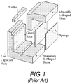
- FIG.1 illustrates the Neumeier cell having a stationary L-shaped base piece with a capacitor plate formed on an inner vertical surface, a moveable L-shaped piece having a second capacitor plate formed on a vertical surface configured to oppose the first capacitor plate, a wedge for wedging a sample between the L-shaped pieces, and a pair of springs for maintaining a counterpoise force against the direction of sample expansion.
- the cell body is composed of fused silica, or quartz.
- Benefits of the Neumeier dilatometer cell include: low expansion due to the all fused-silica construction; the cell is not sensitive to magnetic field; the cell (per se) is not sensitive to temperature; the capacitance readout gives high resolution; large size gives a sizeable capacitance to measure; an Andeen-Hagerling bridge is an excellent off-the-shelf solution for capacitance readout; and the cell can accommodate a range of sample lengths.
- the Neumeier cell presents several problems when used within a low temperature cryostat, such as: capacity is affected by gas adsorption; an absolute capacitance measurement is required; and thermal gradients affect accuracy in 1 st order.
- the dilatometer provides a capacitance measurement based on a ratiometric capacitance, or the capacitance ratio measured between two or more parallel plate capacitors of the dilatometer.
- an absolute capacity bridge is not required, and even more advantageously, the effects of adsorbed gas are greatly reduced compared to conventional dilatometers.
- the ratiometric capacitance dilatometer provides a symmetrical configuration, which reduces the effects of temperature gradients.
- certain embodiments provide a "v-groove design", wherein a first parallel plate capacitor forms an angle with a second parallel plate capacitor of the dilatometer along a key centerline of the dilatometer cell, which improves manufacturability due to simpler grinding, metalizing and assembly.
- a dilatometer cell which is configured to provide a ratiometric capacitance measurement for determining sample expansion.
- spacing between a series of metalized plates allows detection of changes in the length of the specimen.
- the claimed embodiments utilize a ratiometric measurement technique which allows the cell to be first order insensitive to temperature gradients, exchange gas pressure and applied magnetic fields.
- the cell is adapted for mounting in an isothermal chamber, and be rotated with respect to an applied magnetic field, thus making magnetostriction measurements possible in a wide range of temperature ranges.
- FIG.2A shows a front perspective view of a ratiometric capacitance dilatometer cell 100 in accordance with one embodiment; a front side, right side, and top side of the dilatometer cell are shown.
- the dilatometer cell generally comprises a cube made up of a first cell portion having one or more angled protrusions and a second cell portion having one or more angled grooves, the first cell portion being configured to nest with the second cell portion such that one or more respective surfaces of the angled protrusions are configured to oppose and overlap with respective surfaces of the angled grooves.
- the first and second cell portions are nested to form a volume of the dilatometer cell, with two or more overlapping surfaces (four overlapping surfaces are shown).
- the cell has a right side and a left side, each of the right and left sides are configured to about one of two planar sheets referred to herein as a "springs".
- a base portion is attached to the second cell portion, the base portion having opposing notches being disposed on opposite sides thereof. The opposing notches are adapted for mounting the dilatometer cell with a mounting assembly.
- FIG.2B shows a rear perspective view of the ratiometric capacitance dilatometer cell 100 of FIG.2A ; a rear side, left side, and top side of the dilatometer cell are shown.
- the dilatometer can alternatively comprise a cylindrical form or other geometric volume, however, symmetry in the dilatometer design is encouraged for purposes described herein. Those having skill in the art will appreciate that minor fabrication and design deviations will yield substantially similar results.
- the cell is preferably fabricated from a fused silica (quartz), copper alloy and other materials can be used to make a similar dilatometer cell.
- fused silica might be preferable if operation in strong magnetic fields and temperature above 1 K are required
- a cell made of a conductive material, such as a copper alloy might be preferable for use below 1 K and or in a vacuum environment.
- FIG.3 shows a side view of the ratiometric capacitance dilatometer cell 100 with a sample 300 mounted within a first channel 40 and a spring 350 mounted within a second channel 50.
- the spring is optional, but preferred for providing a counterpoise force in a direction opposite of sample expansion.
- FIG.4 shows an exploded view of the ratiometric capacitance dilatometer cell of FIG.3 .
- the dilatometer cell comprises a first cell portion 10, a second cell portion 20, a base portion 30 , a first spring 5a disposed on a left side of the dilatometer, and a second spring 5b disposed on a right side of the dilatometer.
- the first cell portion 10 further comprises at least one angled protrusion (two are shown), each of the angled protrusions 8a ; 8b comprising a pair of planar surfaces oriented at an angle with respect to one another. Each of the planar surfaces are individually metalized or otherwise configured to form or couple with a conductive plate about an area of the respective planar surface.
- the first cell portion comprises a first pair of conductive plates 11 ; 12 oriented at a first angle with respect to one another, and a second pair of conductive plates 13 ; 14 oriented at a second angle with respect to one another.
- four conductive plates are illustrated, the first cell portion can be configured with two or more conductive plates forming one or more angled protrusions.
- the left and right sides of the first cell portion can comprise an edge configured to receive and at least partially abut a sheet spring 5a ; 5b , respectively.
- the sheet spring can be glued or otherwise bonded to an exterior surface of each of the left and right sides of the first cell portion.
- the second cell portion 20 further comprises at least one angled groove (two are shown), each of the angled grooves 9a ; 9b comprising a pair of planar surfaces oriented at an angle with respect to one another. Each of the planar surfaces are individually metalized or otherwise configured to form or couple with a conductive plate about an area of the respective planar surface.
- the second cell portion comprises a third pair of conductive plates 21 ; 22 oriented at a third angle with respect to one another, and a fourth pair of conductive plates 23 ; 24 oriented at a fourth angle with respect to one another.
- the second cell portion can be configured with two or more conductive plates forming one or more angled grooves.
- the left and right sides of the second cell portion can comprise an edge configured to receive and at least partially abut a surface of the sheet spring 5a ; 5b , respectively.
- the sheet spring can be glued or otherwise bonded to an exterior surface of each of the left and right sides of the second cell portion in a manner similar to that of the first cell portion.
- the first cell portion When nested together, the first cell portion fits with the second cell portion with a small gap therebetween to create two or more parallel plate capacitors.
- the sheet springs 5a ; 5b may be configured to assist in maintaining a gap between the first and second cell portions. For instance, as illustrated in FIGs 3-4 , the first conductive plate 11 of the first cell portion 10 at least partially overlaps with the first conductive plate 21 of the second cell portion 20 , forming a first parallel plate capacitor 201 having a first capacitive region defined by a gap extending between the first conductive plates 11 ; 21 .
- the second conductive plate 12 of the first cell portion 10 at least partially overlaps with the second conductive plate 22 of the second cell portion 20 , forming a second parallel plate capacitor 202 having a second capacitive region defined by a gap extending between the second conductive plates 12 ; 22 .
- a third and a fourth parallel plate capacitor 203 ; 204, respectively, are illustrated as being disposed between the first and second cell portions.
- the third parallel plate capacitor is formed between conductive plate 13 and conductive plate 23 ; whereas the fourth parallel plate capacitor is formed between conductive plate 14 and conductive plate 24 .
- the opposing conductive plates of the dilatometer cell form a capacitor having a capacitance C as a function of the surface area A, distance between the plates d, and the permittivity ⁇ of the medium existing between the plates:
- C T ⁇ T A T / d T ; for a given temperature T.
- the first parallel plate capacitor 201 is said to be oriented with the second parallel plate capacitor 202 at an angle therebetween.
- the angle between the first and second parallel plate capacitors can comprise one of: an obtuse angle, an acute angle or a right angle.
- one of the first and second parallel plate capacitors is configured to increase a gap therebetween and decrease capacitance as a function of the distance change, whereas another of the first and second parallel plate capacitors is configured to decrease a gap therebetween and increase capacitance as a function of the distance change.
- the dilatometer is configured to provide a ratiometric measurement of the capacitance between the two or more capacitors, or the capacitance ratio, as opposed to direct capacitance readout.
- This ratiometric capacitance measurement reduces the effects of adsorbed gas (the dilatometer is measured in a sample chamber of a cryostat containing cryogen gas), among other things.
- the conductive plates of the respective parallel plate capacitors can be formed from any method in the art for creating a metalized surface on a volume, such as attaching a conductive sheet, printing a conductive ink, or otherwise depositing metals or other conductive materials on a surface to be metalized.
- a first channel 40 extends vertically across the gap 60 from the first cell portion to the second cell portion, and comprises a first wall 41 disposed on the first cell portion and a second wall 42 disposed on the second cell portion at a side opposite with respect to the first wall 41 .
- a sample is inserted between the first wall 41 and the second wall 42 such that as the sample increases in size, the first and second walls are configured to shift away from one another along the centerline of the cell. This shift results in a change in the capacitance which can be detected by an associated measurement system, such as for example a physical property measurement system (PPMS) manufactured by Quantum Design, Inc. as described above.
- PPMS physical property measurement system
- a second channel 50 may be optionally provided, the second channel 50 extends vertically across the gap 60 from the first cell portion to the second cell portion, and comprises a first wall 51 disposed on the first cell portion and a second wall 52 disposed on the second cell portion at a side opposite with respect to the first wall 51 .
- the second channel is similar to the first channel as described above, however, instead of a sample the second channel is configured to receive a spring 350 for providing a counterpoise force in a direction opposite of sample expansion along the centerline of the cell.
- a base 30 is provided for mounting the dilatometer 100 within a sample chamber of a specimen probe.
- the base comprise a first notch 31 extending along a first side of the base and a second notch 32 extending along a second side of the base opposite of the first side.
- the base can be configured to receive a portion of a clip for maintaining the dilatometer cell against a mounting platform of a specimen probe or within a sample chamber thereof.
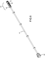
- FIG.5 shows a static specimen probe containing the ratiometric capacitance dilatometer cell in accordance with an embodiment.
- the static probe comprises a probe shaft 151a ; 151b extending from a proximal end to a distal end, and comprises a platform housing 153 disposed at the distal end.
- the probe may contain one or more radiation baffle spacers 152 for isolating the lower volume of the probe from radiation present in the upper portions.
- the platform housing comprises at least one fixed platform configured to receive a dilatometer cell mounted thereon.
- the dilatometer cell 100 is configured to be mounted at any angle with respect to an applied magnetic field, with said angle being fixed by the platform and associated mounting position of the attached dilatometer cell.
- the dilatometer may comprise a base portion 30 designed to engage with a mounting platform of the probe.
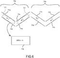
- FIG 6 shows an electrical configuration of the dilatometer cell in accordance with an embodiment.
- Two sets of capacitors in a "parallel" configuration form the fixed (i.e. rigid with respect to the dilatometer cell probe in which it is mounted) transmitter positive plates, the fixed transmitter negative plates and the movable receiver plates which will be shifted either to the right or left according to the sample expansion or restriction.
- the shift of the receiver plates will reduce the gap and thus capacitance of the first set of capacitors, and increase the gap and thus capacitance of the second set of capacitors.
- a first capacitor C1 is formed by a first transmitter negative plate 73a having an area " A " and being disposed in parallel with respect to a first receiver plate 71a at a distance d1 therefrom.
- a second capacitor C2 is formed by a first transmitter positive plate 74a having an associated area and being disposed in parallel with respect to a second receiver plate 72a .
- the first capacitor C1 and the second capacitor C2 form a first capacitor set 70a .
- the dilatometer may comprise two or more sets of capacitors as shown; wherein a third capacitor is formed by plates 71b and 73b at a distance d3 therebetween, and a fourth capacitor is formed by plates 72b and 74b at a distance d4 therebetween.
- the third and fourth capacitors form a second set of capacitors 70b .
- a ratiometric measurement is performed between the two sets of capacitors with an effective area A and gaps d1 and d2.
- the microprocessor in the circuit will adjust the voltage amplitude ratio across the variable inductors by an amount ⁇ U to compensate for the change in gap across each of the two capacitors.
- FIG.7 shows an electrical schematic of the dilatometer cell and related detection system in accordance with an embodiment.
- a processor is coupled to a user interface and configured to measure a ratiometric change in capacitance of the dilatometer cell as a result of a corresponding dimensional change of a mounted sample.
- the processor is configured to receive a balance signal and adjust each of the amplitude of the drive signal and the ratio of the transformer signals.
- the dilatometer cell itself is indicated as the portion of the circuit contained within the dashed oval.
- the dilatometer cell comprises a first capacitor C1 and a second capacitor 2 as described above.
- the dilatometer cell is coupled to a pre-amp and an output signal is communicated through a demodulator, a low pass filter and an A/D converter.
- FIG 8 shows a specimen probe configured to rotate an attached dilatometer cell at various angles for introducing various magnetic field characteristics during a testing procedure.
- the specimen probe is capable of rotational adjustment while the probe is inserted into the cryostat. This capability provides adjustable positioning of the dilatometer in between and during sample measurements.
- the rotator probe comprises an actuator 81 disposed at a proximal end of an actuating shaft 82 , the actuating shaft extends from the proximal end to a distal end to a platform housing 83 .
- the platform housing 83 contains a platform mount 86 , the platform being coupled to the actuator shaft 82 via a geared mechanism 85 at a pivot 84 .
- the actuator 81 when the actuator 81 is adjusted by a user, at least a portion of the actuating shaft rotates, communicating movement through the pivot 84 and coupled geared mechanism 85 , such that the platform 86 rotates accordingly, thereby rotating the dilatometer cell mounted thereon.
- the dilatometer cell can be rotated within the cryostat at various angles (ex: 0 degrees, 90 degrees, etc.) with respect to an applied magnetic field.
- This set up enables a user to study the physics of magnetostriction, which is the change in shape due to an applied magnetic field (usually found in ferromagnetic material). This change is caused by the magnetic field's interaction with a material's magnetic moment.
- a static probe as illustrated in the embodiment of FIG.5 may be used, however, in such embodiment the dilatometer must be removed from the probe and remounted thereon at a rotated orientation in order to accomplish measurements at various angles.
- the claimed invention is applicable to industries related to materials research and development.
Landscapes
- Physics & Mathematics (AREA)
- General Physics & Mathematics (AREA)
- Biochemistry (AREA)
- Life Sciences & Earth Sciences (AREA)
- Chemical & Material Sciences (AREA)
- Analytical Chemistry (AREA)
- Health & Medical Sciences (AREA)
- General Health & Medical Sciences (AREA)
- Immunology (AREA)
- Pathology (AREA)
- Investigating Or Analyzing Materials By The Use Of Electric Means (AREA)
- Investigating Or Analyzing Materials Using Thermal Means (AREA)
- Measurement Of Length, Angles, Or The Like Using Electric Or Magnetic Means (AREA)
Claims (15)
- Ultraempfindliche Kapazitätsverhältnis-Dilatometerzelle (100), welche umfasst:einen ersten Zellbereich (10), welcher dergestalt konfiguriert ist, dass er mit einem zweiten Zellbereich (20) verschachtelt ist, so dass ein Zellvolumen festgelegt wird, wobei der erste Zellbereich (10) und der zweite Zellbereich (20) durch einen sich zwischen ihnen erstreckenden Spalt (60) getrennt sind;einen ersten parallelen Plattenkondensator (201), welcher umfasst:eine erste leitende Platte (11), welche an den ersten Zellbereich (10) angekoppelt ist, undeine zweite leitende Platte (21, welche an den zweiten Zellbereich (20) angekoppelt ist, wobei die erste leitende Platte (11) dergestalt konfiguriert ist, dass sie die zweite leitende Platte (21) zumindest teilweise überlappt;einen zweiten parallelen Plattenkondensator, wobei dieser zweite parallele Plattenkondensator (202) zwischen dem ersten und dem zweiten Zellbereich ausgebildet ist, undeinen Kanal (40), welcher sich quer über den Spalt vom ersten Zellbereich zum zweiten Zellbereich erstreckt, wobei dieser Kanal umfasst:wobei die Dilatometerzelle (100) dergestalt konfiguriert ist, dass zwischen dem ersten und dem zweiten parallelen Plattenkondensator (201, 202) eine Änderung des Kapazitätsverhältnisses gemessen wird, während die Probe zwischen der ersten und der zweiten Wand (41, 42) sich hinsichtlich ihrer Größe verändert.eine erste Wand (41), welche an den ersten Zellbereich (10) angekoppelt ist, undeine zweite Wand (42), welche an den zweiten Wandbereich (20) angekoppelt ist, wobei diese zweite Wand (42) dergestalt konfiguriert ist, dass sie der ersten Wand (41) gegenüber liegt, wobei die erste und die zweite der sich einander gegenüber liegenden Wände (41, 42) dergestalt konfiguriert sind, dass sie zwischen sich eine Probe aufnehmen;
- Dilatometerzelle nach Anspruch 1, bei welcher der genannte zweite parallele Plattenkondensator (202) unter einem bestimmten Winkel in Bezug auf den genannten ersten parallelen Plattenkondensator (201) ausgerichtet ist.
- Dilatometerzelle nach Anspruch 2, bei welcher der genannte Winkel ein spitzer Winkel ist.
- Dilatometerzelle nach Anspruch 2, bei welcher der genannte Winkel ein stumpfer Winkel ist.
- Dilatometerzelle nach Anspruch 1, bei welcher der erste und der zweite Zellbereich jeweils aus einem dielektrischen Material bestehen.
- Dilatometerzelle nach Anspruch 1, bei welcher der erste und der zweite Zellbereich jeweils aus einer Kupferlegierung bestehen.
- Dilatometerzelle nach Anspruch 1, welche eine Wheatstone-Brücke umfasst, in welcher der genannte erste parallele Plattenkondensator (201, C1) einen ersten Zweig und der genannte zweite parallele Plattenkondensator (201, C2) einen zweiten Zweig der Wheatstone-Brücke bilden.
- Dilatometerzelle nach Anspruch 7, bei welcher ein erstes induktives Bauelement an den ersten Kondensator über eine erste leitende Spur angekoppelt ist und ein zweites induktives Bauelement an den zweiten Kondensator über eine zweite leitende Spur angekoppelt ist, damit die vier Zweige der Wheatstone-Brücke gebildet werden.
- Dilatometerzelle nach Anspruch 8, bei welcher das erste und das zweite induktive Bauelement sich außerhalb der Dilatometerzelle befinden und über die erste und die zweite leitende Spur verbunden sind.
- Dilatometerzelle nach Anspruch 8, bei welcher mindestens eines von beiden, dem ersten und dem zweiten induktiven Bauelement, sich auf oder innerhalb der Dilatometerzelle befinden.
- Dilatometerzelle nach Anspruch 1, bei welcher die genannte erste und zweite leitende Platte metallisierte Oberflächen des ersten und zweiten Zellbereichs umfassen.
- Dilatometerzelle nach Anspruch 1, bei welcher die sich einander gegenüber liegenden leitenden Platten der Dilatometerzelle einen Kondensator bilden, welcher für eine gegebene Temperatur T die Kapazität C als Funktion der Oberfläche A, des Abstandes zwischen den Platten d und der Dielektrizitätskonstanten ε des zwischen den Platten befindlichen Mediums hat gemäß:

- Dilatometerzelle nach Anspruch 1, bei welcher die erste und die zweite der beiden einander gegenüber liegenden Wände (41. 42) dergestalt konfiguriert sind, dass sie eine Probe aufnehmen, welche eine charakteristische Länge von etwa 2 mm aufweist.
- Dilatometerzelle nach Anspruch 1, welche außerdem eine modulare Träger-Schnittstelle für den Einsatz mit vielgestaltigen Montageplattformen umfasst, wobei die genannten Plattformen eine stationäre Plattform und eine Drehvorrichtung enthalten.
- Benutzung des Dilatometers nach Anspruch 1 für die Erfassung der thermischen Ausdehnung und der Magnetostriktion einer Probe bei Anwesenheit von mindestens einer der Größen variabler Temperaturgradient und variabler Magnetfeldgradient in einer Testkammer.
Applications Claiming Priority (3)
| Application Number | Priority Date | Filing Date | Title |
|---|---|---|---|
| US201361774256P | 2013-03-07 | 2013-03-07 | |
| US14/042,665 US8992077B2 (en) | 2013-03-07 | 2013-09-30 | Ultrasensitive ratiometric capacitance dilatometer and related methods |
| PCT/US2014/021940 WO2014138635A1 (en) | 2013-03-07 | 2014-03-07 | Ultrasensitive ratiometric capacitance dilatometer and related methods |
Publications (3)
| Publication Number | Publication Date |
|---|---|
| EP2965069A1 EP2965069A1 (de) | 2016-01-13 |
| EP2965069A4 EP2965069A4 (de) | 2016-10-12 |
| EP2965069B1 true EP2965069B1 (de) | 2018-10-31 |
Family
ID=51487763
Family Applications (1)
| Application Number | Title | Priority Date | Filing Date |
|---|---|---|---|
| EP14760499.5A Not-in-force EP2965069B1 (de) | 2013-03-07 | 2014-03-07 | Ultraempfindliches kapazitätsverhältnis-dilatometer und zugehörige verfahren |
Country Status (5)
| Country | Link |
|---|---|
| US (1) | US8992077B2 (de) |
| EP (1) | EP2965069B1 (de) |
| JP (1) | JP6388885B2 (de) |
| CN (1) | CN105190297B (de) |
| WO (1) | WO2014138635A1 (de) |
Families Citing this family (6)
| Publication number | Priority date | Publication date | Assignee | Title |
|---|---|---|---|---|
| CN105684332B (zh) * | 2013-09-20 | 2019-06-18 | 皇家飞利浦有限公司 | 用于设计体耦合通信装置的设计工具和方法 |
| RU2645823C1 (ru) * | 2016-12-20 | 2018-02-28 | Федеральное государственное бюджетное научное учреждение "Федеральный исследовательский центр "Красноярский научный центр Сибирского отделения Российской академии наук" | Емкостный дилатометр для работы в составе установки PPMS QD |
| CN112213353B (zh) * | 2020-09-09 | 2021-10-22 | 中国科学院金属研究所 | 一种线膨胀系数的测试方法 |
| CN112326720B (zh) * | 2020-10-30 | 2022-05-20 | 河海大学 | 一种mems多层薄膜材料热膨胀系数的提取方法 |
| RU2766188C1 (ru) * | 2021-06-16 | 2022-02-09 | Федеральное государственное бюджетное учреждение науки Институт физической химии и электрохимии им. А.Н. Фрумкина Российской академии наук (ИФХЭ РАН) | Способы и стенд для измерения деформации гранул нанопористых материалов, стимулированной адсорбцией или температурой дилатометрическим методом |
| CN115655083B (zh) * | 2022-11-02 | 2024-03-08 | 北京工业大学 | 一种不等尺寸8簧片正交布置的水平微位移差动测量装置 |
Family Cites Families (13)
| Publication number | Priority date | Publication date | Assignee | Title |
|---|---|---|---|---|
| FR1583998A (de) | 1967-07-06 | 1969-12-12 | ||
| US3729991A (en) * | 1971-05-17 | 1973-05-01 | Spearhead Inc | Capacitive displacement transducer |
| US4453398A (en) * | 1982-12-15 | 1984-06-12 | Iowa State University Research Foundation, Inc. | Ice porosimeter |
| CN85100656B (zh) * | 1985-04-01 | 1987-09-02 | 中国科学院金属研究所 | 一种石英示差膨胀计 |
| CN1013060B (zh) * | 1987-11-17 | 1991-07-03 | 化学工业部黎明化工研究院 | 一种塑料线膨胀系数测定仪 |
| SU1661634A1 (ru) | 1988-12-01 | 1991-07-07 | Воронежский Политехнический Институт | Дилатометр дл испытани полимерных материалов |
| US6718281B2 (en) | 2000-02-15 | 2004-04-06 | Virginia Polytechnic Institute & State University | Apparatus and method for volumetric dilatometry |
| EP1843138B1 (de) * | 2006-04-06 | 2012-05-16 | Sauer-Danfoss ApS | Schraube mit einer Schicht aus leitfähigem Material, das einen Sensor bildet |
| ES2442249T3 (es) * | 2006-08-02 | 2014-02-10 | Air Products And Chemicals, Inc. | Método y aparato para controlar la presión de fluidos |
| CN201589757U (zh) * | 2010-01-11 | 2010-09-22 | 浙江伟星新型建材股份有限公司 | 塑料管材线膨胀系数测试仪 |
| DE102010010348A1 (de) * | 2010-03-05 | 2011-09-08 | Albert-Ludwigs-Universität Freiburg | Implantierbare Vorrichtung zum Erfassen einer Gefäßwanddehnung |
| DE102011051561A1 (de) * | 2011-07-05 | 2013-01-10 | BÄHR-Thermoanalyse GmbH | Dilatometer zur Messung von metallischen Proben |
| DE102012109841B4 (de) * | 2011-11-17 | 2019-01-10 | MAX-PLANCK-Gesellschaft zur Förderung der Wissenschaften e.V. | Miniatur-Dilatometer für die Messungen der thermischen Ausdehnung und der Magnetostriktion zur Verwendung innerhalb eines Multifunktionseinsatzes eines PPMS-Gerätes |
-
2013
- 2013-09-30 US US14/042,665 patent/US8992077B2/en active Active
-
2014
- 2014-03-07 EP EP14760499.5A patent/EP2965069B1/de not_active Not-in-force
- 2014-03-07 JP JP2015560403A patent/JP6388885B2/ja not_active Expired - Fee Related
- 2014-03-07 CN CN201480012275.5A patent/CN105190297B/zh not_active Expired - Fee Related
- 2014-03-07 WO PCT/US2014/021940 patent/WO2014138635A1/en not_active Ceased
Non-Patent Citations (1)
| Title |
|---|
| None * |
Also Published As
| Publication number | Publication date |
|---|---|
| WO2014138635A1 (en) | 2014-09-12 |
| CN105190297A (zh) | 2015-12-23 |
| JP6388885B2 (ja) | 2018-09-12 |
| CN105190297B (zh) | 2018-08-10 |
| US8992077B2 (en) | 2015-03-31 |
| US20140254624A1 (en) | 2014-09-11 |
| EP2965069A1 (de) | 2016-01-13 |
| EP2965069A4 (de) | 2016-10-12 |
| JP2016516183A (ja) | 2016-06-02 |
Similar Documents
| Publication | Publication Date | Title |
|---|---|---|
| US8992077B2 (en) | Ultrasensitive ratiometric capacitance dilatometer and related methods | |
| Küchler et al. | A compact and miniaturized high resolution capacitance dilatometer for measuring thermal expansion and magnetostriction | |
| US4098000A (en) | Crack opening displacement gage | |
| Hosseini et al. | A polymer–semiconductor–ceramic cantilever for high-sensitivity fluid-compatible microelectromechanical systems | |
| CN114112092A (zh) | 一种传感器环境温度测量电路及传感器 | |
| Genossar et al. | A tilted‐plate capacitance displacement sensor | |
| Duan et al. | Wireless gas sensing based on a passive piezoelectric resonant sensor array through near-field induction | |
| Chen et al. | Highly sensitive resonant sensor using quartz resonator cluster for inclination measurement | |
| Ding et al. | A novel PQCR-L circuit for inductive sensing and its application in displacement detection | |
| US20190003857A1 (en) | Sensor and sensor element | |
| EP1381837A1 (de) | Kapazitives dynamometer | |
| CN112284656B (zh) | 一种零长弹簧刚度和漂移量一体化批量检测系统及方法 | |
| Sydenham et al. | Low-cost, precision, flat inductive sensor | |
| Etingof | Modern vernier caliper | |
| Wejgaard et al. | Contactless measurement of electrical resistivity by eddy current methods: discussion and a new technique | |
| EP0721564B1 (de) | Hochpräzisionswaage und positionssensor | |
| Li et al. | Analysis and elimination of translation disturbance for patch effect measurement with a torsion pendulum | |
| Toth et al. | A low-cost, stable reference capacitor for capacitive sensor systems | |
| US4548515A (en) | Multiple sensor dilatometer | |
| Kong et al. | A novel ultra-simplified flexure-based spring-mass device for relative gravimeter | |
| Gao et al. | Primary thermometry below 25 K: a decade of low-uncertainty measurements linked to the New Kelvin | |
| CN120558152A (zh) | 一种通过振荡器表征金属基材表面金属薄膜厚度方法 | |
| Prabhu et al. | MEMS-based Magnetoelastic Sensor for the Detection of Creatinine Molecules-A Conceptual Evaluation | |
| Hornauer et al. | Sensor head for measurement of stress anisotropy in thin films | |
| CN115060414A (zh) | 一种提供高精度压力标准的装置及方法 |
Legal Events
| Date | Code | Title | Description |
|---|---|---|---|
| PUAI | Public reference made under article 153(3) epc to a published international application that has entered the european phase |
Free format text: ORIGINAL CODE: 0009012 |
|
| 17P | Request for examination filed |
Effective date: 20151006 |
|
| AK | Designated contracting states |
Kind code of ref document: A1 Designated state(s): AL AT BE BG CH CY CZ DE DK EE ES FI FR GB GR HR HU IE IS IT LI LT LU LV MC MK MT NL NO PL PT RO RS SE SI SK SM TR |
|
| AX | Request for extension of the european patent |
Extension state: BA ME |
|
| DAX | Request for extension of the european patent (deleted) | ||
| A4 | Supplementary search report drawn up and despatched |
Effective date: 20160913 |
|
| RIC1 | Information provided on ipc code assigned before grant |
Ipc: G01B 7/16 20060101ALI20160907BHEP Ipc: G01N 27/22 20060101ALN20160907BHEP Ipc: G01N 25/16 20060101AFI20160907BHEP |
|
| GRAP | Despatch of communication of intention to grant a patent |
Free format text: ORIGINAL CODE: EPIDOSNIGR1 |
|
| STAA | Information on the status of an ep patent application or granted ep patent |
Free format text: STATUS: GRANT OF PATENT IS INTENDED |
|
| RIC1 | Information provided on ipc code assigned before grant |
Ipc: G01N 27/22 20060101ALN20180509BHEP Ipc: G01B 7/16 20060101ALI20180509BHEP Ipc: G01N 25/16 20060101AFI20180509BHEP |
|
| RIC1 | Information provided on ipc code assigned before grant |
Ipc: G01B 7/16 20060101ALI20180516BHEP Ipc: G01N 27/22 20060101ALN20180516BHEP Ipc: G01N 25/16 20060101AFI20180516BHEP |
|
| INTG | Intention to grant announced |
Effective date: 20180613 |
|
| GRAS | Grant fee paid |
Free format text: ORIGINAL CODE: EPIDOSNIGR3 |
|
| GRAA | (expected) grant |
Free format text: ORIGINAL CODE: 0009210 |
|
| STAA | Information on the status of an ep patent application or granted ep patent |
Free format text: STATUS: THE PATENT HAS BEEN GRANTED |
|
| AK | Designated contracting states |
Kind code of ref document: B1 Designated state(s): AL AT BE BG CH CY CZ DE DK EE ES FI FR GB GR HR HU IE IS IT LI LT LU LV MC MK MT NL NO PL PT RO RS SE SI SK SM TR |
|
| REG | Reference to a national code |
Ref country code: CH Ref legal event code: EP Ref country code: GB Ref legal event code: FG4D |
|
| REG | Reference to a national code |
Ref country code: AT Ref legal event code: REF Ref document number: 1059989 Country of ref document: AT Kind code of ref document: T Effective date: 20181115 |
|
| REG | Reference to a national code |
Ref country code: DE Ref legal event code: R096 Ref document number: 602014035147 Country of ref document: DE |
|
| REG | Reference to a national code |
Ref country code: IE Ref legal event code: FG4D |
|
| REG | Reference to a national code |
Ref country code: NL Ref legal event code: MP Effective date: 20181031 |
|
| REG | Reference to a national code |
Ref country code: LT Ref legal event code: MG4D |
|
| REG | Reference to a national code |
Ref country code: AT Ref legal event code: MK05 Ref document number: 1059989 Country of ref document: AT Kind code of ref document: T Effective date: 20181031 |
|
| PG25 | Lapsed in a contracting state [announced via postgrant information from national office to epo] |
Ref country code: ES Free format text: LAPSE BECAUSE OF FAILURE TO SUBMIT A TRANSLATION OF THE DESCRIPTION OR TO PAY THE FEE WITHIN THE PRESCRIBED TIME-LIMIT Effective date: 20181031 Ref country code: LV Free format text: LAPSE BECAUSE OF FAILURE TO SUBMIT A TRANSLATION OF THE DESCRIPTION OR TO PAY THE FEE WITHIN THE PRESCRIBED TIME-LIMIT Effective date: 20181031 Ref country code: PL Free format text: LAPSE BECAUSE OF FAILURE TO SUBMIT A TRANSLATION OF THE DESCRIPTION OR TO PAY THE FEE WITHIN THE PRESCRIBED TIME-LIMIT Effective date: 20181031 Ref country code: HR Free format text: LAPSE BECAUSE OF FAILURE TO SUBMIT A TRANSLATION OF THE DESCRIPTION OR TO PAY THE FEE WITHIN THE PRESCRIBED TIME-LIMIT Effective date: 20181031 Ref country code: BG Free format text: LAPSE BECAUSE OF FAILURE TO SUBMIT A TRANSLATION OF THE DESCRIPTION OR TO PAY THE FEE WITHIN THE PRESCRIBED TIME-LIMIT Effective date: 20190131 Ref country code: NO Free format text: LAPSE BECAUSE OF FAILURE TO SUBMIT A TRANSLATION OF THE DESCRIPTION OR TO PAY THE FEE WITHIN THE PRESCRIBED TIME-LIMIT Effective date: 20190131 Ref country code: LT Free format text: LAPSE BECAUSE OF FAILURE TO SUBMIT A TRANSLATION OF THE DESCRIPTION OR TO PAY THE FEE WITHIN THE PRESCRIBED TIME-LIMIT Effective date: 20181031 Ref country code: FI Free format text: LAPSE BECAUSE OF FAILURE TO SUBMIT A TRANSLATION OF THE DESCRIPTION OR TO PAY THE FEE WITHIN THE PRESCRIBED TIME-LIMIT Effective date: 20181031 Ref country code: AT Free format text: LAPSE BECAUSE OF FAILURE TO SUBMIT A TRANSLATION OF THE DESCRIPTION OR TO PAY THE FEE WITHIN THE PRESCRIBED TIME-LIMIT Effective date: 20181031 Ref country code: IS Free format text: LAPSE BECAUSE OF FAILURE TO SUBMIT A TRANSLATION OF THE DESCRIPTION OR TO PAY THE FEE WITHIN THE PRESCRIBED TIME-LIMIT Effective date: 20190228 |
|
| PG25 | Lapsed in a contracting state [announced via postgrant information from national office to epo] |
Ref country code: SE Free format text: LAPSE BECAUSE OF FAILURE TO SUBMIT A TRANSLATION OF THE DESCRIPTION OR TO PAY THE FEE WITHIN THE PRESCRIBED TIME-LIMIT Effective date: 20181031 Ref country code: RS Free format text: LAPSE BECAUSE OF FAILURE TO SUBMIT A TRANSLATION OF THE DESCRIPTION OR TO PAY THE FEE WITHIN THE PRESCRIBED TIME-LIMIT Effective date: 20181031 Ref country code: GR Free format text: LAPSE BECAUSE OF FAILURE TO SUBMIT A TRANSLATION OF THE DESCRIPTION OR TO PAY THE FEE WITHIN THE PRESCRIBED TIME-LIMIT Effective date: 20190201 Ref country code: NL Free format text: LAPSE BECAUSE OF FAILURE TO SUBMIT A TRANSLATION OF THE DESCRIPTION OR TO PAY THE FEE WITHIN THE PRESCRIBED TIME-LIMIT Effective date: 20181031 Ref country code: PT Free format text: LAPSE BECAUSE OF FAILURE TO SUBMIT A TRANSLATION OF THE DESCRIPTION OR TO PAY THE FEE WITHIN THE PRESCRIBED TIME-LIMIT Effective date: 20190301 Ref country code: AL Free format text: LAPSE BECAUSE OF FAILURE TO SUBMIT A TRANSLATION OF THE DESCRIPTION OR TO PAY THE FEE WITHIN THE PRESCRIBED TIME-LIMIT Effective date: 20181031 |
|
| PG25 | Lapsed in a contracting state [announced via postgrant information from national office to epo] |
Ref country code: CZ Free format text: LAPSE BECAUSE OF FAILURE TO SUBMIT A TRANSLATION OF THE DESCRIPTION OR TO PAY THE FEE WITHIN THE PRESCRIBED TIME-LIMIT Effective date: 20181031 Ref country code: DK Free format text: LAPSE BECAUSE OF FAILURE TO SUBMIT A TRANSLATION OF THE DESCRIPTION OR TO PAY THE FEE WITHIN THE PRESCRIBED TIME-LIMIT Effective date: 20181031 Ref country code: IT Free format text: LAPSE BECAUSE OF FAILURE TO SUBMIT A TRANSLATION OF THE DESCRIPTION OR TO PAY THE FEE WITHIN THE PRESCRIBED TIME-LIMIT Effective date: 20181031 |
|
| REG | Reference to a national code |
Ref country code: DE Ref legal event code: R097 Ref document number: 602014035147 Country of ref document: DE |
|
| PG25 | Lapsed in a contracting state [announced via postgrant information from national office to epo] |
Ref country code: SK Free format text: LAPSE BECAUSE OF FAILURE TO SUBMIT A TRANSLATION OF THE DESCRIPTION OR TO PAY THE FEE WITHIN THE PRESCRIBED TIME-LIMIT Effective date: 20181031 Ref country code: RO Free format text: LAPSE BECAUSE OF FAILURE TO SUBMIT A TRANSLATION OF THE DESCRIPTION OR TO PAY THE FEE WITHIN THE PRESCRIBED TIME-LIMIT Effective date: 20181031 Ref country code: SM Free format text: LAPSE BECAUSE OF FAILURE TO SUBMIT A TRANSLATION OF THE DESCRIPTION OR TO PAY THE FEE WITHIN THE PRESCRIBED TIME-LIMIT Effective date: 20181031 Ref country code: EE Free format text: LAPSE BECAUSE OF FAILURE TO SUBMIT A TRANSLATION OF THE DESCRIPTION OR TO PAY THE FEE WITHIN THE PRESCRIBED TIME-LIMIT Effective date: 20181031 |
|
| PLBE | No opposition filed within time limit |
Free format text: ORIGINAL CODE: 0009261 |
|
| STAA | Information on the status of an ep patent application or granted ep patent |
Free format text: STATUS: NO OPPOSITION FILED WITHIN TIME LIMIT |
|
| 26N | No opposition filed |
Effective date: 20190801 |
|
| PG25 | Lapsed in a contracting state [announced via postgrant information from national office to epo] |
Ref country code: SI Free format text: LAPSE BECAUSE OF FAILURE TO SUBMIT A TRANSLATION OF THE DESCRIPTION OR TO PAY THE FEE WITHIN THE PRESCRIBED TIME-LIMIT Effective date: 20181031 Ref country code: MC Free format text: LAPSE BECAUSE OF FAILURE TO SUBMIT A TRANSLATION OF THE DESCRIPTION OR TO PAY THE FEE WITHIN THE PRESCRIBED TIME-LIMIT Effective date: 20181031 |
|
| PGFP | Annual fee paid to national office [announced via postgrant information from national office to epo] |
Ref country code: DE Payment date: 20190719 Year of fee payment: 6 |
|
| REG | Reference to a national code |
Ref country code: CH Ref legal event code: PL |
|
| PG25 | Lapsed in a contracting state [announced via postgrant information from national office to epo] |
Ref country code: LU Free format text: LAPSE BECAUSE OF NON-PAYMENT OF DUE FEES Effective date: 20190307 |
|
| REG | Reference to a national code |
Ref country code: BE Ref legal event code: MM Effective date: 20190331 |
|
| PGFP | Annual fee paid to national office [announced via postgrant information from national office to epo] |
Ref country code: GB Payment date: 20190719 Year of fee payment: 6 |
|
| PG25 | Lapsed in a contracting state [announced via postgrant information from national office to epo] |
Ref country code: CH Free format text: LAPSE BECAUSE OF NON-PAYMENT OF DUE FEES Effective date: 20190331 Ref country code: LI Free format text: LAPSE BECAUSE OF NON-PAYMENT OF DUE FEES Effective date: 20190331 Ref country code: IE Free format text: LAPSE BECAUSE OF NON-PAYMENT OF DUE FEES Effective date: 20190307 |
|
| PG25 | Lapsed in a contracting state [announced via postgrant information from national office to epo] |
Ref country code: FR Free format text: LAPSE BECAUSE OF NON-PAYMENT OF DUE FEES Effective date: 20190331 Ref country code: BE Free format text: LAPSE BECAUSE OF NON-PAYMENT OF DUE FEES Effective date: 20190331 |
|
| PG25 | Lapsed in a contracting state [announced via postgrant information from national office to epo] |
Ref country code: TR Free format text: LAPSE BECAUSE OF FAILURE TO SUBMIT A TRANSLATION OF THE DESCRIPTION OR TO PAY THE FEE WITHIN THE PRESCRIBED TIME-LIMIT Effective date: 20181031 |
|
| PG25 | Lapsed in a contracting state [announced via postgrant information from national office to epo] |
Ref country code: MT Free format text: LAPSE BECAUSE OF NON-PAYMENT OF DUE FEES Effective date: 20190307 |
|
| REG | Reference to a national code |
Ref country code: DE Ref legal event code: R119 Ref document number: 602014035147 Country of ref document: DE |
|
| PG25 | Lapsed in a contracting state [announced via postgrant information from national office to epo] |
Ref country code: DE Free format text: LAPSE BECAUSE OF NON-PAYMENT OF DUE FEES Effective date: 20201001 |
|
| GBPC | Gb: european patent ceased through non-payment of renewal fee |
Effective date: 20200307 |
|
| PG25 | Lapsed in a contracting state [announced via postgrant information from national office to epo] |
Ref country code: GB Free format text: LAPSE BECAUSE OF NON-PAYMENT OF DUE FEES Effective date: 20200307 |
|
| PG25 | Lapsed in a contracting state [announced via postgrant information from national office to epo] |
Ref country code: CY Free format text: LAPSE BECAUSE OF FAILURE TO SUBMIT A TRANSLATION OF THE DESCRIPTION OR TO PAY THE FEE WITHIN THE PRESCRIBED TIME-LIMIT Effective date: 20181031 |
|
| PG25 | Lapsed in a contracting state [announced via postgrant information from national office to epo] |
Ref country code: HU Free format text: LAPSE BECAUSE OF FAILURE TO SUBMIT A TRANSLATION OF THE DESCRIPTION OR TO PAY THE FEE WITHIN THE PRESCRIBED TIME-LIMIT; INVALID AB INITIO Effective date: 20140307 |
|
| PG25 | Lapsed in a contracting state [announced via postgrant information from national office to epo] |
Ref country code: MK Free format text: LAPSE BECAUSE OF FAILURE TO SUBMIT A TRANSLATION OF THE DESCRIPTION OR TO PAY THE FEE WITHIN THE PRESCRIBED TIME-LIMIT Effective date: 20181031 |