EP2965043B1 - Magnetic linear or rotary encoder - Google Patents
Magnetic linear or rotary encoder Download PDFInfo
- Publication number
- EP2965043B1 EP2965043B1 EP14712611.4A EP14712611A EP2965043B1 EP 2965043 B1 EP2965043 B1 EP 2965043B1 EP 14712611 A EP14712611 A EP 14712611A EP 2965043 B1 EP2965043 B1 EP 2965043B1
- Authority
- EP
- European Patent Office
- Prior art keywords
- rotary encoder
- linear
- magnetic field
- encoder
- permanent magnets
- Prior art date
- Legal status (The legal status is an assumption and is not a legal conclusion. Google has not performed a legal analysis and makes no representation as to the accuracy of the status listed.)
- Active
Links
Images


Classifications
-
- G—PHYSICS
- G01—MEASURING; TESTING
- G01D—MEASURING NOT SPECIALLY ADAPTED FOR A SPECIFIC VARIABLE; ARRANGEMENTS FOR MEASURING TWO OR MORE VARIABLES NOT COVERED IN A SINGLE OTHER SUBCLASS; TARIFF METERING APPARATUS; MEASURING OR TESTING NOT OTHERWISE PROVIDED FOR
- G01D5/00—Mechanical means for transferring the output of a sensing member; Means for converting the output of a sensing member to another variable where the form or nature of the sensing member does not constrain the means for converting; Transducers not specially adapted for a specific variable
- G01D5/12—Mechanical means for transferring the output of a sensing member; Means for converting the output of a sensing member to another variable where the form or nature of the sensing member does not constrain the means for converting; Transducers not specially adapted for a specific variable using electric or magnetic means
- G01D5/14—Mechanical means for transferring the output of a sensing member; Means for converting the output of a sensing member to another variable where the form or nature of the sensing member does not constrain the means for converting; Transducers not specially adapted for a specific variable using electric or magnetic means influencing the magnitude of a current or voltage
- G01D5/20—Mechanical means for transferring the output of a sensing member; Means for converting the output of a sensing member to another variable where the form or nature of the sensing member does not constrain the means for converting; Transducers not specially adapted for a specific variable using electric or magnetic means influencing the magnitude of a current or voltage by varying inductance, e.g. by a movable armature
- G01D5/22—Mechanical means for transferring the output of a sensing member; Means for converting the output of a sensing member to another variable where the form or nature of the sensing member does not constrain the means for converting; Transducers not specially adapted for a specific variable using electric or magnetic means influencing the magnitude of a current or voltage by varying inductance, e.g. by a movable armature differentially influencing two coils
- G01D5/2208—Mechanical means for transferring the output of a sensing member; Means for converting the output of a sensing member to another variable where the form or nature of the sensing member does not constrain the means for converting; Transducers not specially adapted for a specific variable using electric or magnetic means influencing the magnitude of a current or voltage by varying inductance, e.g. by a movable armature differentially influencing two coils by influencing the self-induction of the coils
- G01D5/2216—Mechanical means for transferring the output of a sensing member; Means for converting the output of a sensing member to another variable where the form or nature of the sensing member does not constrain the means for converting; Transducers not specially adapted for a specific variable using electric or magnetic means influencing the magnitude of a current or voltage by varying inductance, e.g. by a movable armature differentially influencing two coils by influencing the self-induction of the coils by a movable ferromagnetic element, e.g. a core
-
- G—PHYSICS
- G01—MEASURING; TESTING
- G01D—MEASURING NOT SPECIALLY ADAPTED FOR A SPECIFIC VARIABLE; ARRANGEMENTS FOR MEASURING TWO OR MORE VARIABLES NOT COVERED IN A SINGLE OTHER SUBCLASS; TARIFF METERING APPARATUS; MEASURING OR TESTING NOT OTHERWISE PROVIDED FOR
- G01D5/00—Mechanical means for transferring the output of a sensing member; Means for converting the output of a sensing member to another variable where the form or nature of the sensing member does not constrain the means for converting; Transducers not specially adapted for a specific variable
- G01D5/12—Mechanical means for transferring the output of a sensing member; Means for converting the output of a sensing member to another variable where the form or nature of the sensing member does not constrain the means for converting; Transducers not specially adapted for a specific variable using electric or magnetic means
- G01D5/14—Mechanical means for transferring the output of a sensing member; Means for converting the output of a sensing member to another variable where the form or nature of the sensing member does not constrain the means for converting; Transducers not specially adapted for a specific variable using electric or magnetic means influencing the magnitude of a current or voltage
- G01D5/142—Mechanical means for transferring the output of a sensing member; Means for converting the output of a sensing member to another variable where the form or nature of the sensing member does not constrain the means for converting; Transducers not specially adapted for a specific variable using electric or magnetic means influencing the magnitude of a current or voltage using Hall-effect devices
- G01D5/145—Mechanical means for transferring the output of a sensing member; Means for converting the output of a sensing member to another variable where the form or nature of the sensing member does not constrain the means for converting; Transducers not specially adapted for a specific variable using electric or magnetic means influencing the magnitude of a current or voltage using Hall-effect devices influenced by the relative movement between the Hall device and magnetic fields
-
- G—PHYSICS
- G01—MEASURING; TESTING
- G01D—MEASURING NOT SPECIALLY ADAPTED FOR A SPECIFIC VARIABLE; ARRANGEMENTS FOR MEASURING TWO OR MORE VARIABLES NOT COVERED IN A SINGLE OTHER SUBCLASS; TARIFF METERING APPARATUS; MEASURING OR TESTING NOT OTHERWISE PROVIDED FOR
- G01D2205/00—Indexing scheme relating to details of means for transferring or converting the output of a sensing member
- G01D2205/20—Detecting rotary movement
- G01D2205/26—Details of encoders or position sensors specially adapted to detect rotation beyond a full turn of 360°, e.g. multi-rotation
-
- G—PHYSICS
- G01—MEASURING; TESTING
- G01D—MEASURING NOT SPECIALLY ADAPTED FOR A SPECIFIC VARIABLE; ARRANGEMENTS FOR MEASURING TWO OR MORE VARIABLES NOT COVERED IN A SINGLE OTHER SUBCLASS; TARIFF METERING APPARATUS; MEASURING OR TESTING NOT OTHERWISE PROVIDED FOR
- G01D2205/00—Indexing scheme relating to details of means for transferring or converting the output of a sensing member
- G01D2205/40—Position sensors comprising arrangements for concentrating or redirecting magnetic flux
-
- G—PHYSICS
- G01—MEASURING; TESTING
- G01D—MEASURING NOT SPECIALLY ADAPTED FOR A SPECIFIC VARIABLE; ARRANGEMENTS FOR MEASURING TWO OR MORE VARIABLES NOT COVERED IN A SINGLE OTHER SUBCLASS; TARIFF METERING APPARATUS; MEASURING OR TESTING NOT OTHERWISE PROVIDED FOR
- G01D3/00—Indicating or recording apparatus with provision for the special purposes referred to in the subgroups
- G01D3/028—Indicating or recording apparatus with provision for the special purposes referred to in the subgroups mitigating undesired influences, e.g. temperature, pressure
- G01D3/036—Indicating or recording apparatus with provision for the special purposes referred to in the subgroups mitigating undesired influences, e.g. temperature, pressure on measuring arrangements themselves
Definitions
- the invention relates to a magnetic linear or rotary encoder laid down in the preamble of claim 1.
- Art Such donors are, for example, in the publications DE 10 2007 039 050 A1 and DE 10 2010 022 154 A1 described.
- the invention has for its object to provide a magnetic linear or rotary encoder of the type mentioned, in which the measurement accuracy can be significantly increased.
- the invention is based on the finding that the use of the ratiometric difference method for obtaining highly accurate measurement results as a sufficient condition for the assumption that in every possible position and at any time the percentage change of the affected by environmental parameters field of view in all magnetic field sensors of the fine resolution Sensor unit is the same at least during a measuring cycle.
- the ferromagnetic elements in order to achieve the object sought by the invention, it is generally sufficient to subject at least the ferromagnetic elements to a heat treatment which is in the immediate vicinity of the exciting magnetic field, e.g. the return body and the deflecting body.
- the excitation magnetic field must be shielded from the outside so that existing residual field strengths, by the temperature-dependent ferromagnetic components, such as. B. the hood used for shielding, may experience fluctuations, no longer exert on the measurement result.
- the return and the deflecting body made of a tempered ferromagnetic metal, preferably MU metal.
- a one-piece design of deflection and return body is advantageous, but this is not absolutely necessary if the magnetic effect of a one-piece body is achieved by magnetically separated body.
- the deflecting body moves with the excitation unit, that is to say e.g. at a rotary encoder rotates with this.
- the senor receives in addition to the annealed return body a ferromagnetic screen, but does not need to be tempered. Its task is to weaken external fields to such an extent that in the interior covered by the MU metal body the residual field approaches zero or only perpendicular (perpendicular) to the magnetic field sensors standing (additive) interference fields occur. Since tempered elements are shock-sensitive, because their crystal structure can be restored to their original state by impact, the non-tempered screen also serves as mechanical protection.
- the pot-shaped or trough-shaped return body together with the deflecting body serves to shield the exciter field to the outside.
- a linear or rotary magnetic encoder is provided by said steps, in which the ratiometric difference method is on a perfect theoretical basis and leads to measurement results of the highest accuracy.
- a rotary encoder 1 is shown with a shaft 3 which can rotate about its central longitudinal axis 5 in both directions, as indicated by the double arrow R.
- This shaft 3 may be the shaft to be monitored itself or an encoder shaft, which is mechanically coupled to the shaft that is actually to be monitored, for example by a transmission, so that it clearly reflects its rotational movement.
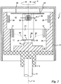
- a rotationally symmetrical support 7 made of a non-ferromagnetic material, such as plastic, aluminum, brass or the like rotatably mounted. He wears on his away from the wave 3, in the Fig. 1 overhead, flat end face a non-rotatably connected to him excitation unit 8, which comprises a circular cylindrical, rotationally symmetrical to the longitudinal axis 5 pot 9 of ferromagnetic material.
- the inner cavity of the pot 9 has here in the axial direction adjacent sections 11, 12 with different diameters.
- the section 11 with the smaller diameter is immediately adjacent to the perpendicular to the longitudinal axis 5 extending bottom 14 of the pot 9, while the more outer portion 12 opens with a larger diameter in the overhead opening of the pot 9.
- two diametrically opposed primary permanent magnets 16, 17 symmetrically mounted to the axis of rotation 5 so that they rest with one of its two poles on the inner wall of the pot 9, while their free, inwardly directed poles N and Assign S to each other.
- the magnetic dipoles of the primary permanent magnets 16, 17 preferably all run in the same direction as defined by the two magnetization vectors which are pointing through their respective center of gravity and pointing in the same direction.
- a central field space is formed, which connects the two primary permanent magnets 16, 17 directly.
- the two permanent magnets 16, 17, each of which may extend in the circumferential direction, for example, over an angular range of 45 °, magnetically connected to each other by the pot forming a return body 9.
- the two magnets are preferably the same size and have approximately the same magnetic field strength.
- the magnetic field formed between its poles is deformed by a deflecting body 18, which is arranged concentrically to the longitudinal axis 5 and made of ferromagnetic material, which projects upwards from the bottom 14 of the pot 9 in the direction of the longitudinal axis 5 and has a circular ground plan.
- the deformation of the measuring magnetic field has the consequence that not all magnetic field lines, which emanate from one of the primary permanent magnets 16 and 17, more or less straight and parallel to the bottom 14 of the pot 9 to each other primary permanent magnet 17 and 16 extend, as is shown for the magnetic field line 21, but that some field lines start at one of the two poles N and S but are bent so that they open into the deflecting 18, as shown schematically for the two lines 22, 23.
- a platinum-shaped support (not shown) made of a non-ferromagnetic material is fixed, i. mounted so that it does not join the rotation of the shaft 3, the pot 9 and the primary permanent magnets 16, 17.
- an integrated circuit (IC) 24 is mounted, in which, for example, four magneto-sensitive elements 25, 26, 27, 28 are formed (in section the Fig. 1 only the two magneto-sensitive elements 27 and 26 are visible) whose active surfaces extend in a plane parallel to the bottom 14 of the pot 9 and perpendicular to the axis of rotation 5.
- each of the four magneto-sensitive elements 25, 26, 27, 28 in the region of one of the four corners of the IC 24 is arranged so that in the plan view plane their mutual distances are substantially greater than their dimensions in this plane (up to 50 times large).
- the IC 24 may contain all or at least parts of the electronic circuits required to evaluate their output signals and determine the fine position value therefrom.
- the active surfaces of the four magneto-sensitive elements 25, 26, 27, 28 are displaced from the magnetic field lines 22, 23 with a perpendicular to them, i. to the longitudinal axis 5 parallel component passes through, so that electrical signals b, c, d, a can be tapped at their outputs whose amplitudes change upon rotation of the shaft 3 and thus the exciter unit 8, so that from them the respective instantaneous angular position of Wave 3 can be determined.
- the four square-Hall elements are each connected diagonally (cross) in two groups, according to the not previously published DE 10 2012 002 204 the mutual distances of the Hall elements are large compared to their diameter.
- a counting unit 30 is arranged in the further outward section 12 of the bore of the pot 9, which comprises a Wiegand wire 31 extending approximately parallel to the bottom 14 of the pot 9 and a coil 32 surrounding this wire, both of which a fixed, ie the rotation of the exciter unit 8 are not mounted mitmachem carrier 33, to which the IC 24 is attached.
- two further permanent magnets 34, 35 are mounted in the same manner as described above for the two primary permanent magnets 16, 17; Although they may have the same thickness and thickness as the primary permanent magnets 16, 17, but their mutually facing poles N, S have a greater distance than the poles N, S of the primary permanent magnets 16, 17, because the working field strength of the Wieganddrahtes 31st smaller than the Hall probes is.
- the two further permanent magnets 34, 35 could also be omitted and the counting unit 30 can be arranged in the upper stray field region of the two primary permanent magnets 16, 17.
- the counting unit 30 requires fields whose correct field strength for a perfect working is narrowly defined.
- the axial distance of the Wiegand wire 31 from the central region of the magnetic field of the primary permanent magnets 16, 17 would therefore have to be set and maintained relatively accurately, which is possible in many applications.
- the variant shown is preferable, because it allows the Wiegand wire 31 with a sufficiently large distance from the field of the primary permanent magnets 16, 17 to arrange and its working field strength by an appropriate design of the other permanent magnets 34, 35 optimally and independently of the to make the magneto-sensitive elements 25, 26, 27, 28 passing field strength.
- the disturbances that the Wiegand wire can exert when switching to the measuring field are minimized by the return element 9 and by the largest possible distance of the Wiegand wire from the measuring magnetic field.
- an inventive encoder essentially corresponds to a combination of donors, in the pamphlets DE 10 2007 039 050 A1 and DE 10 2010 022 154 A1 are described. In particular, in the latter a ferromagnetic deflecting body is described, which rotates with the shaft and thus also with the exciter unit.
- the pot 9 and the deflecting body 18 are annealed, so that no changes in their crystalline structure occur during temperature fluctuations and can distort the existing magnetic field in the measuring field space unevenly.
- the housing of the fine resolution sensor unit 29 contains no ferromagnetic components, because this is necessarily located in the vicinity of the exciter magnets.
- the erroneous influence of such a ferromagnetic housing on the measurement result is exorbitant.
- a fixedly arranged, e.g. trained as a hood screen 38 of soft iron surrounds the pot 9 largely and protects one hand, its open top against the penetration of foreign magnetic fields and the other hand, the entire pot 9 against shocks that could put back its crystalline structure in the original, not tempered state.
- the axial length with which the screen 38 engages the pot 9 may vary within the limits dictated by the need to fulfill these two protective functions.
- the screen 38 can serve for holding the carrier 33 for the counting unit 30 and thus also for the fine-resolution sensor unit 29. It is essential that there are no ferromagnetic bodies in the interior enclosed by the pot 9, whose crystal structures change with temperature. Therefore, both the primary and the further permanent magnets 16, 17 and 34, 35 are preferably annealed.
- Fig. 2 shown full-wave generator 1 is with the off Fig. 1 almost identical, so that it suffices to describe below only the slight differences between the two variants, which essentially consist in the fact that the return body is no longer formed by a closed bottom pot but a ring 39 made of a tempered, ferromagnetic material, which is no longer integrally connected to the deflection body 18 but separated from it by an annular air gap 37.
- the carrier 7 of non-ferromagnetic material has in comparison to Fig. 1 a larger diameter and is both with the ring 39 as also rotatably connected to the deflecting 18. Since the air gap 37 can be kept substantially smaller in practice, as in Fig. 2 In this embodiment as well, it is ensured that the measuring magnetic field is sufficiently protected against magnetic changes of the shaft.
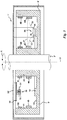
- a rotary encoder 1 ' which is used as a so-called “hollow shaft encoder” in waves 3' used, the two ends must remain free for connection to other components.
- the ferromagnetic yoke body is formed as an annular trough 9 'with a U-shaped cross section, the right angle from the bottom 14' upstanding side walls 40, 41 surround the shaft 3 'concentric, with the inner side wall 40 of the trough 9' is rotatably connected ,
- the deflecting body 18 'made of ferromagnetic material is here also integrally connected to the bottom 14' of the trough 9 'and protrudes from this upwards so that its overhead, flat surface has a concentric to the shaft 3' annular floor plan and to both Side walls 40, 41, for example, has the same distances.
- Analogous to that related to Fig. 1 described alternative may also be the deflecting as an independent, separate from the return body, be carried out with this co-rotating component made of ferromagnetic material.
- the housing of the sensor elements does not comprise ferromagnetic components.
- the sensor chip can also be bonded directly to a circuit board. In this case, however, mechanical stress can be expected, which again makes the measuring system temperature-dependent.
- mechanical stress can be expected, which again makes the measuring system temperature-dependent.
- the exciting unit 8 'here comprises a plurality, ie two or more arranged on the inner sides of the side walls pairs of opposing, with their respective opposing poles facing each other primary permanent magnet, of which Fig. 3 only the two pairs 43, 44 and 45, 46 are visible.
- These pairs of primary Permanent magnets have the same angular intervals in the circumferential direction and have alternating polarities, so that on each of the side walls 40, 41 in the circumferential direction on a with its north pole in the interior of the trough 9 'facing primary permanent magnet follows a next, the south pole is facing the trough interior, etc ,
- the other permanent magnets 48, 49, 50, 51 which serve to enumerate the measuring intervals, which are predetermined by the primary permanent magnet pairs 43, 44 and 45, 46 and so on.
- the interior of the trough 9 ' is not discontinued here, so that the inner surfaces of its side walls 40, 41 have the same distance from each other everywhere.
- the further permanent magnet pairs 48, 49 and 50, 51 arranged in the upper region are thinner and weaker than the primary permanent magnet pairs 43, 44 and 45, 46 arranged closer to the bottom 14 '.
- a screen 38 'made of soft iron is provided, which at least encloses the tempered trough 9' so far that it is protected against mechanical shocks and no disturbing external fields in the interior of the trough 9 'can penetrate.
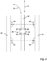
- the IC 24 is shown disproportionately large in order to make it clear that the four magneto-sensitive elements 25, 26, 27, 28, which are preferably Hall probes, are arranged at large mutual distances in its four corner areas , The four magneto-sensitive elements are circuitally combined into pairs 28, 27 and 26, 25 so that the differences of their output signals ad and. cb are formed.
- each pair run radially or perpendicular to the direction of movement R.
- the groups 28, 27 and 26, 25, each consisting of two sensor elements each deliver an approximately sinusoidal signal.
- the phase shift of these two signals can be arbitrary and is here according to Fig. 4 in about 45 °.
- the signals a, b, c, d represent only addresses for the hollow shaft encoder and linear encoder, under which the measured setpoint values m are stored in a memory are.
- the return body assembly can be formed by two mutually parallel plates, between which the deflecting body runs as a rectilinear web.
- FIGS. 5 and 6 it is a solid shaft encoder 1, in which the return body 9 of the excitation unit 8 forms a bottom closed pot, as in the embodiment of Fig. 1 the case is.
- the deflecting 18 'characterized magnetically separated from the yoke body, that it is embedded in a non-ferromagnetic body 19 (eg plastic, aluminum, brass and the like.) Which connects him rotatably connected to the exciter unit.
- the deflecting body 18 directs the part of the magnetic field in its vicinity between the permanent magnets 16, 17, which is symbolized by the magnetic field lines 22, 23, so that the four magnetosensitive elements 25, 26, 27 and 28 (of which on average the Fig. 5 only the elements 27 and 26 are visible) with a longitudinal axis 5 parallel component of the magnetic field lines 22, 23 are penetrated.
- the magnetosensitive elements 25, 26, 27 and 28 are formed in an IC 24 which is arranged so that its active surfaces the deflecting 18 'face and are located at a small distance from this.
- the further permanent magnets 34, 35 of the full-wave generator are made Fig. 1 omitted, and the counting unit 30 is disposed in the upper stray field region of the two primary permanent magnets 16, 17.
- the compounds of the two groups in turn extend perpendicular to the direction of movement in the Fig. 6 Exciter unit 8, not shown, whose axis of rotation pierces the center of the arrangement forming intersection of the two dashed, mutually perpendicular lines 53, 54 perpendicular to the plane, the double arrow R symbolizes the direction of rotation of the encoder 1.
Description
Die Erfindung betrifft einen magnetischen Linear- oder Drehgeber der im Oberbegriff von Anspruch 1 niedergelegten Art. Solche Geber sind beispielsweise in den Druckschriften
In
In der Praxis zeigt sich jedoch, dass auch bei Verwendung des ratiometrischen Differenzen-Verfahrens die Messergebnisse aufgrund von Umwelteinflüssen schwanken, wodurch die erzielbare Genauigkeit in unerwünschter Weise begrenzt wird.In practice, however, shows that even when using the ratiometric difference method, the measurement results vary due to environmental influences, whereby the achievable accuracy is undesirably limited.
Somit liegt der Erfindung die Aufgabe zugrunde, einen magnetischen Linear- oder Drehgeber der eingangs genannten Art zu schaffen, bei dem sich die Messgenauigkeit erheblich steigern lässt.Thus, the invention has for its object to provide a magnetic linear or rotary encoder of the type mentioned, in which the measurement accuracy can be significantly increased.
Zur Lösung dieser Aufgabe sieht die Erfindung die im Anspruch 1 zusammengefassten Merkmale vor.To solve this problem, the invention provides the features summarized in
Der Erfindung liegt die Erkenntnis zugrunde, dass die Verwendung des ratiometrischen Differenzen-Verfahrens für die Erzielung hochgenauer Messergebnisse als hinreichende Bedingung zur Voraussetzung hat, dass in jeder möglichen Position und zu jedem Zeitpunkt die prozentuale Änderung des durch Umweltparameter beeinflussten Messfeldes in allen Magnetfeldsensoren der Feinauflösungs-Sensoreinheit zumindest während eines Messzyklusses gleich ist. Unter Messzyklus wird die Zeitdauer verstanden, in der der Linear- oder Drehgeber einen einzelnen Messwert bestimmter Genauigkeit und Auflösung generiert. Diese Bedingung ist erfüllt, wenn die kristalline Struktur des ferromagnetischen Kreises in einem definierten Bereich sich ändernder Umweltparameter generell homogen oder im einfachsten Fall in erster Näherung unverändert bleibt (magnetischer Widerstand des Messkreises Rm = konstant). Damit ist z.B. gewährleistet, dass der Zusammenhang zwischen dem Erregermagnetfeld und den von jedem der Magnetfeldsensoren wahrgenommenen Messfeldern linear ist.The invention is based on the finding that the use of the ratiometric difference method for obtaining highly accurate measurement results as a sufficient condition for the assumption that in every possible position and at any time the percentage change of the affected by environmental parameters field of view in all magnetic field sensors of the fine resolution Sensor unit is the same at least during a measuring cycle. Measuring cycle is understood to mean the period in which the linear or rotary encoder generates a single measured value of specific accuracy and resolution. This condition is met when the crystalline structure of the ferromagnetic circuit in a defined range of changing environmental parameters generally homogeneous or in the simplest case unchanged in the first approximation (magnetic resistance of the measuring circuit R m = constant). This ensures, for example, that the relationship between the excitation magnetic field and the measurement fields perceived by each of the magnetic field sensors is linear.
Sind a, b, c und d die Signale der entsprechenden Magnetfeldsensoren und γ, η Faktoren einer multiplikative Störgröße und Δ eine additive Störgröße, dann gilt im Idealfall (η = 1) für den Messwert m bei einem Vollwellen-Drehgeber wenn reine Sinus- und Kosinussignale vorliegen: 
Ferromagnetische Materialien ändern insbesondere mit der Temperatur ihr Gefüge und damit ihre magnetischen Eigenschaften stark. Daher sollten gemäß der Erfindung grundsätzlich alle ferromagnetischen Teile des Gebers, mit denen das Messfeld in Berührung kommt, getempert, d.h. einer Wärmebehandlung unterzogen werden, damit ihre Kristallstruktur soweit stabilisiert wird, dass sie sich bei normalen Temperaturschwankungen (d.h. in einem Temperaturbereich von ca. -50°C bis ca. +150°C) nicht verändert bzw. homogen bleibt.Ferromagnetic materials change their structure, and thus their magnetic properties, especially with temperature. Therefore, according to the invention, in principle all the ferromagnetic parts of the sensor with which the measuring field comes into contact should be annealed, i. be subjected to a heat treatment so that their crystal structure is stabilized so far that it does not change or remain homogeneous under normal temperature fluctuations (i.e., in a temperature range of about -50 ° C to about + 150 ° C).
Zur Erreichung des durch die Erfindung angestrebten Zieles reicht es jedoch im allgemeinen aus, zumindest die ferromagnetischen Elemente einer Wärmebehandlung zu unterziehen, die in unmittelbarer Nähe des Erregermagnetfeldes liegen, z.B. den Rückschlusskörper und den Umlenkkörper. In diesem Falle muss allerdings gleichzeitig das Erregermagnetfeld so nach außen abgeschirmt werden, dass vorhandene Restfeldstärken, durch die temperaturabhängige ferromagnetische Komponenten, wie z. B. die zur Abschirmung verwendete Haube, Schwankungen erleiden können, auf das Messergebnis keinen Einfluss mehr ausüben. In Weiterbildung der Erfindung werden deshalb der Rückschluss- und der Umlenkkörper aus einem getemperten ferromagnetischen Metall, vorzugsweise MU-Metall hergestellt.However, in order to achieve the object sought by the invention, it is generally sufficient to subject at least the ferromagnetic elements to a heat treatment which is in the immediate vicinity of the exciting magnetic field, e.g. the return body and the deflecting body. In this case, however, at the same time the excitation magnetic field must be shielded from the outside so that existing residual field strengths, by the temperature-dependent ferromagnetic components, such as. B. the hood used for shielding, may experience fluctuations, no longer exert on the measurement result. In a further development of the invention, therefore, the return and the deflecting body made of a tempered ferromagnetic metal, preferably MU metal.
Vorteilhaft ist eine einstückige Ausbildung von Umlenk- und Rückschlusskörper, doch ist dies nicht unbedingt erforderlich, wenn durch magnetisch getrennte Körper die magnetische Wirkung eines einstückigen Körpers erzielt wird.A one-piece design of deflection and return body is advantageous, but this is not absolutely necessary if the magnetic effect of a one-piece body is achieved by magnetically separated body.
Überdies wird in vorteilhafter Weise vorgesehen, dass lediglich solche elektronischen Bauteile wie ICs und Kondensatoren benutzt werden, die in ihrem Gehäuse keinerlei ferromagnetische Bestandteile enthalten. Wenn das nicht möglich ist, werden diese elektronischen Bauteile so weit vom Erregerfeld entfernt angeordnet, dass die durch Temperaturschwankungen bedingten Änderungen ihrer magnetischen Eigenschaften das Messfeld praktisch nicht mehr beeinflussen können.Moreover, it is advantageously provided that only such electronic components as ICs and capacitors are used, which do not contain any ferromagnetic components in their housing. If this is not possible, these electronic components are placed far enough away from the exciter field that the changes in their magnetic properties due to temperature fluctuations can practically no longer affect the measuring field.
Um eine negative Beeinflussung der Messgenauigkeit durch Hystereseeffekte zu vermeiden, ist es bevorzugt, dass sich der Umlenkkörper mit der Erregereinheit mitbewegt, sich also z.B. bei einem Drehgeber mit dieser dreht.In order to avoid a negative influence on the measurement accuracy due to hysteresis effects, it is preferred that the deflecting body moves with the excitation unit, that is to say e.g. at a rotary encoder rotates with this.
Darüber hinaus müssen von außen kommende, das Messergebnis störende Fremdfelder eliminiert werden. Zu diesem Zweck erhält der Sensor zusätzlich zu dem getemperten Rückschlusskörper einen ferromagnetischen Schirm, der aber nicht getempert werden muss. Seine Aufgabe ist es, Außenfelder soweit zu schwächen, dass in dem vom MU-Metall-Körper umfassten Innenraum das Restfeld gegen null geht oder nur senkrecht zu den Magnetfeldsensoren stehende (additive) Störfelder auftreten. Da getemperte Elemente stoßempfindlich sind, weil ihre Kristallstruktur durch Stöße wieder in den ursprünglichen Zustand zurückversetzt werden kann, dient der nicht getemperte Schirm zugleich als mechanischer Schutz.In addition, extraneous fields that interfere with the measurement result must be eliminated. For this purpose, the sensor receives in addition to the annealed return body a ferromagnetic screen, but does not need to be tempered. Its task is to weaken external fields to such an extent that in the interior covered by the MU metal body the residual field approaches zero or only perpendicular (perpendicular) to the magnetic field sensors standing (additive) interference fields occur. Since tempered elements are shock-sensitive, because their crystal structure can be restored to their original state by impact, the non-tempered screen also serves as mechanical protection.
In vielen Fällen ist es nicht möglich, eine ferromagnetische Geberwelle durch Temperung zu stabilisieren; auch diesbezüglich dient der topf- bzw. trogförmige Rückschlusskörper gemeinsam mit dem Umlenkkörper zur Abschirmung des Erregerfeldes nach au-ßen.In many cases, it is not possible to stabilize a ferromagnetic encoder shaft by annealing; Also in this regard, the pot-shaped or trough-shaped return body together with the deflecting body serves to shield the exciter field to the outside.
Somit wird durch die genannten Schritte ein magnetischer Linear- oder Drehgeber geschaffen, bei dem das ratiometrische Differenzen-Verfahren auf einwandfreier theoretischer Basis steht und zu Messergebnissen höchster Genauigkeit führt.Thus, a linear or rotary magnetic encoder is provided by said steps, in which the ratiometric difference method is on a perfect theoretical basis and leads to measurement results of the highest accuracy.
Die Erfindung wird im Folgenden anhand eines Ausführungsbeispiels unter Bezugnahme auf die Zeichnung beschrieben; in dieser zeigen:
- Fig. 1
- eine stark schematisierte Schnittansicht durch einen erfindungsgemäßen Drehgeber (Vollwellengeber), der auf das freie Ende einer Welle aufgesteckt ist;
- Fig. 2
- einen der
Fig. 1 entsprechenden Schnitt durch eine andere Ausführungsform eines erfindungsgemäßen Vollwellengebers, - Fig. 3
- in einem anderen Maßstab einen den
Fig. 1 und2 entsprechenden Schnitt durch einen erfindungsgemäßen Drehgeber, der eine zentrale durchgehende Bohrung aufweist (Hohlwellengeber), durch welche eine Welle, deren Drehbewegung überwacht werden soll, so hindurch gesteckt ist, dass ihre beiden Enden frei zugänglich sind, - Fig. 4
- in einem anderen Maßstab eine Draufsicht auf die rechte Seite der Anordnung aus
Fig. 3 in Richtung des Pfeils I, - Fig. 5
- einen der
Fig. 1 entsprechenden Schnitt durch eine weitere Ausführungsform eines erfindungsgemäßen Vollwellengebers, und - Fig. 6
- eine Draufsicht auf die Feinauflösungs-Sensoreinheit des Vollwellengebers aus
Fig. 5 in Richtung der Drehachse .
- Fig. 1
- a highly schematic sectional view through a rotary encoder according to the invention (Vollwellengeber), which is attached to the free end of a shaft;
- Fig. 2
- one of the
Fig. 1 corresponding section through another embodiment of a solid shaft encoder according to the invention, - Fig. 3
- on another scale, the one
Fig. 1 and2 corresponding section through a rotary encoder according to the invention, which has a central through hole (hollow shaft encoder), through which a shaft whose rotation is to be monitored, is inserted through it so that its two ends are freely accessible, - Fig. 4
- on a different scale from a plan view of the right side of the arrangement
Fig. 3 in the direction of arrow I, - Fig. 5
- one of the
Fig. 1 corresponding section through a further embodiment of a Vollwellengebers invention, and - Fig. 6
- a plan view of the fine resolution sensor unit of the Vollwellengebers from
Fig. 5 in the direction of the axis of rotation.
In den Figuren werden gleiche bzw. einander entsprechende Teile mit gleichen, in den
In
Auf dem in der
Der Innenhohlraum des Topfes 9 weist hier zwei in axialer Richtung aneinander anschließende Abschnitte 11, 12 mit unterschiedlichen Durchmessern auf. Der Abschnitt 11 mit dem kleineren Durchmesser schließt sich unmittelbar an den senkrecht zur Längsachse 5 verlaufenden Boden 14 des Topfes 9 an, während der weiter außen liegende Abschnitt 12 mit größerem Durchmesser in die oben liegende Öffnung des Topfes 9 mündet.The inner cavity of the
Auf der Innenwand des unteren Abschnittes 11 sind zwei einander diametral gegenüberliegende primäre Permanentmagnete 16, 17 symmetrisch zur Drehachse 5 so montiert, dass sie mit jeweils einem ihrer beiden Pole an der Innenwand des Topfes 9 anliegen, während ihre freien, nach innen gerichteten Pole N und S aufeinander zuweisen. Die magnetischen Dipole der primären Permanentmagneten 16, 17 verlaufen vorzugsweise alle in der gleichen Richtung, die durch die ihre beiden sich durch ihren jeweiligen Schwerpunkt ersteckenden, in die gleiche Richtung weisenden Magnetisierungsvektoren definiert ist. Somit wird eine Zentralfeldraum gebildet, der die beiden primären Permanentmagnete 16, 17 direkt verbindet.On the inner wall of the
Durch diese Anordnung sind die beiden Permanentmagnete 16, 17, von denen sich jeder in Umfangsrichtung beispielsweise über einen Winkelbereich von 45° erstrecken kann, durch den einen Rückschlusskörper bildenden Topf 9 magnetisch miteinander verbunden.By this arrangement, the two
Die beiden Magnete sind vorzugsweise gleich groß und besitzen in etwa die gleiche Magnetfeldstärke.The two magnets are preferably the same size and have approximately the same magnetic field strength.
Das zwischen ihren Polen ausgebildete Magnetfeld wird durch einen konzentrisch zur Längsachse 5 angeordneten Umlenkkörper 18 aus ferromagnetischem Material verformt, der vom Boden 14 des Topfes 9 in Richtung der Längsachse 5 nach oben vorsteht und einen kreisförmigen Grundriss besitzt.The magnetic field formed between its poles is deformed by a deflecting
Die Verformung des Messmagnetfeldes hat zur Folge, dass sich nicht alle Magnetfeldlinien, die von einem der primären Permanentmagneten 16 und 17 ausgehen, mehr oder weniger geradlinig und parallel zum Boden 14 des Topfes 9 zum jeweils anderen primären Permanentmagneten 17 bzw. 16 erstrecken, wie dies für die Magnetfeldlinie 21 dargestellt ist, sondern dass einige Feldlinien zwar bei einem der beiden Pole N bzw. S beginnen aber so umgebogen werden, dass sie in den Umlenkkörper 18 münden, wie dies für die beiden Linien 22, 23 schematisch wiedergegeben ist.The deformation of the measuring magnetic field has the consequence that not all magnetic field lines, which emanate from one of the primary
Im Bereich des verformten Magnetfeldes, d.h. mit geringem axialen Abstand oberhalb der oberen Fläche des Umlenkkörpers 18 ist ein (nicht dargestellter) platinenförmiger Träger aus einem nicht ferromagnetischen Material feststehend, d.h. so montiert, dass er die Drehung der Welle 3, des Topfes 9 und der primären Permanentmagneten 16, 17 nicht mitmacht.In the region of the deformed magnetic field, i. At a small axial distance above the upper surface of the
An der Unterseite des Trägers ist ein integrierter Schaltkreis (IC) 24 montiert, in dem beispielsweise vier magnetosensitive Elemente 25, 26, 27, 28 ausgebildet sind (im Schnitt der
Die aktiven Flächen der vier magnetosensitive Elemente 25, 26, 27, 28 werden von den Magnetfeldlinien 22, 23 mit einer zu ihnen senkrechten, d.h. zur Längsachse 5 parallelen Komponente durchsetzt, so dass an ihren Ausgängen elektrische Signale b, c, d, a abgegriffen werden können, deren Amplituden sich bei einer Drehung der Welle 3 und damit der Erregereinheit 8 ändern, so dass aus ihnen die jeweilige momentane Winkelstellung der Welle 3 ermittelt werden kann.The active surfaces of the four magneto-
Der IC 24 bildet zusammen mit den in ihm ausgebildeten magnetosensitiven Elementen 25, 26, 27, 28, bei denen es sich beispielsweise um Hallsonden handeln kann, eine Feinauflösungs-Sensoreinheit 29, die es erlaubt, die momentane Winkelposition der Welle 3 im jeweiligen Messwinkel-Intervall mit hoher Genauigkeit zu ermitteln.The
Bei dem in
Dadurch, dass sich der Umlenkkörper 18 mit dem von der Erregereinheit 8 erzeugten Messmagnetfeld mitdreht, werden das Messergebnis verfälschende Hystereseeffekte vollständig eliminiert.The fact that the deflecting
Sind auf der Innenseite des Topfes 9 im unteren Abschnitt 11 optimal nur zwei primäre Permanentmagnete 16, 17 angeordnet, so ergeben sich zwei Messintervalle, bei deren Durchlaufen an den Ausgängen der verschalteten magnetosensitiven Elemente 28, 27 ein sinusförmiges Signal und 26, 25 ein kosinusförmiges Signal. abgegriffen werden können, die sich jeweils über einen elektrischen Winkel von 180° erstrecken, so dass einem geometrischen Rotationswinkel der Welle 3 von 360° auch ein Paar von periodisches Signalen mit einer Phase von jeweils 360° entspricht.If optimally only two primary
Um bei Drehungen von mehr als 360° eine eindeutige Winkelstellung zu ermitteln, ist es erforderlich, die durchlaufenen Messintervalle zu zählen. Dies gilt auch dann, wenn mehr als zwei Paare von einander diametral gegenüberliegenden primären Permanentmagneten vorgesehen sind, so dass jeweils bei einer Drehung der Welle 3 über 360° mehr als zwei Messintervalle überstrichen werden.In order to determine a definite angular position for rotations of more than 360 °, it is necessary to count the running measuring intervals. This also applies if more than two pairs of diametrically opposed primary permanent magnets are provided so that in each case more than two measuring intervals are swept over 360 ° when the
Zu diesem Zweck ist in dem weiter außen liegenden Abschnitt 12 der Bohrung des Topfes 9 eine Zähleinheit 30 angeordnet, die einen sich in etwa parallel zum Boden 14 des Topfes 9 erstreckenden Wiegand-Draht 31 und eine diesen Draht umgebenden Spule 32 umfasst, die beide an einem feststehenden, d.h. die Drehung der Erregereinheit 8 nicht mitmachenden Träger 33 montiert sind, an dem auch der IC 24 befestigt ist.For this purpose, a
An der Innenwand des Abschnittes 12 mit größerem Durchmesser sind zwei weitere, Permanentmagnete 34, 35 in der gleichen Weise montiert, wie dies zuvor für die beiden primären Permanentmagnete 16, 17 beschrieben wurde; sie können zwar die gleiche Dicke und Stärke wie die primären Permanentmagnete 16, 17 besitzen, doch weisen ihre aufeinander zu weisenden Pole N, S einen größeren Abstand als die Pole N, S der primären Permanentmagnete 16, 17 auf, weil die Arbeitsfeldstärke des Wieganddrahtes 31 kleiner als die der Hallsonden ist.On the inner wall of the
Anstelle eines abgesetzten Topfes mit gleich dicken Magneten 16, 17 und 34, 35 kann auch ein durchgehender Topf mit Magneten verschiedener Dicke oder verschiedenen magnetischen Eigenschaften verwendet werdenInstead of a stepped pot with equally
Prinzipiell könnten die beiden weiteren Permanentmagnete 34, 35 auch weggelassen und die Zähleinheit 30 im oberen Streufeldbereich der beiden primären Permanentmagnete 16, 17 angeordnet werden. Eine solche Positionierung ist aber vergleichsweise kritisch, weil die Zähleinheit 30 für ein einwandfreies Arbeiten Felder benötigt, deren Feldstärke eng definiert ist. Der axiale Abstand des Wiegand-Drahtes 31 vom Zentralbereich des Magnetfeldes der primären Permanentmagnete 16, 17 müsste deshalb relativ genau festgelegt und eingehalten werden, was in vielen Anwendungsfällen aber möglich ist.In principle, the two further
Daher ist die dargestellte Variante vorzuziehen, weil sie es erlaubt, den Wiegand-Draht 31 mit ausreichend großem Abstand vom Feld der primären Permanentmagnete 16, 17 anzuordnen und seine Arbeits-Feldstärke durch eine entsprechende Auslegung der weiteren Permanentmagnete 34, 35 optimal und unabhängig von der die magnetosensitiven Elemente 25, 26, 27, 28 durchsetzenden Feldstärke zu gestalten. Die Störungen, die der Wiegand-Draht beim Schalten auf das Messfeld ausüben kann, werden durch den Rückschlussköper 9 sowie durch einen möglichst großen Abstand des Wiegand-Drahtes vom Mess-Magnetfeld minimiert.Therefore, the variant shown is preferable, because it allows the
Immer dann, wenn der die weiteren Permanentmagnete 34, 35 verbindende Durchmesser eine bestimmte Winkelstellung bezüglich des Wiegand-Drahtes 31 durchläuft, wird in diesem in bekannter Weise eine Ummagnetisierung bewirkt, die zur Erzeugung eines Spannungsimpulses an den Ausgängen der Spule 32 führt, der sowohl als Zählimpuls für die Zählung der durchlaufenen Messintervalle als auch als Stromversorgungsimpuls für die (nicht dargestellte) Verarbeitungselektronik dient, die ebenfalls auf dem Träger 33 montiert sein kann, wenn sie keine ferromagnetischen Bestandteile enthält.. Zur Drehrichtungserkennung kann in an sich bekannter Weise ein hier nicht dargestelltes zusätzliches keine ferromagnetischen Bestandteile enthaltendes Sensorelement vorgesehen sein, das auf das oder die Magnetfelder der Erregereinheit 8 einmal je Messintervall anspricht.Whenever the diameter connecting the further
Sowohl hinsichtlich seiner bisher beschriebenen geometrischen Ausgestaltung als auch seiner Funktion als Multiturn, der sowohl jedes der einzelnen Messintervalle mit hoher Genauigkeit auflösen als auch die die Anzahl der durchlaufenen Messintervalle unter Berücksichtigung der Drehrichtung abzählen kann, entspricht ein erfindungsgemäßer Drehgeber im Wesentlichen einer Kombination der Geber, die in den Druckschriften
Ein wesentlicher Unterschied des im vorliegenden Beispiel gezeigten Drehgebers gegenüber diesem Stand der Technik besteht darin, dass der ferromagnetische Rückschlusskörper der Erregereinheit 8 einen bodenseitig geschlossenen Topf 9 bildet und der Umlenkkörper 18 nicht von der zu überwachenden Welle bzw. der Geberwelle 3 gebildet wird. Er kann entweder, wie in
Den flachen Boden des Topfes 9 unmittelbar zur Umlenkung der Magnetfeldlinien zu verwenden, wäre ungünstig, weil hierdurch das Messfeld zu schwach ausgebildet wird.To use the flat bottom of the
Durch den geschlossenen Boden des Topfes 9 wird eine weitgehende Abschirmung des Mess-Magnetfeldes zur Welle 3 hin erreicht, sodass deren magnetischen Änderungen keine Rückwirkungen auf das Mess-Magnetfeld haben können. Außerdem werden durch die Welle von außen eingekoppelte Fremdmagnetfelder in ausreichendem Maße geschwächt bzw. symmetrisiert.Due to the closed bottom of the
Weiterhin ist gemäß der Erfindung vorgesehen, dass der Topf 9 und der Umlenkkörper 18 getempert sind, sodass bei Temperaturschwankungen keine Veränderungen ihres kristallinen Gefüges auftreten und das im Messfeldraum vorhandene Magnetfeld ungleichmäßig verzerren können.Furthermore, it is provided according to the invention that the
Ganz wesentlich ist die Bedingung, dass das Gehäuse der Feinauflösungs-Sensoreinheit 29 keine ferromagnetischen Bestandteile enthält, weil dieses zwangsläufig in der Nähe der Erregermagnete angeordnet ist. Der z.B. bei Temperaturveränderungen auftretende, fehlerhafte Einfluss eines solchen ferromagnetischen Gehäuses auf das Messergebnis ist exorbitant.Quite essential is the condition that the housing of the fine
Ein feststehend angeordneter, z.B. als Haube ausgebildeter Schirm 38 aus Weicheisen umschließt den Topf 9 weitgehend und schützt einerseits seine offene Oberseite gegen das Eindingen von magnetischen Fremdfeldern und andererseits den gesamten Topf 9 gegen Stöße, die sein kristallines Gefüge wieder in den ursprünglichen, nicht getemperten Zustand zurückversetzen könnten. Die axiale Länge, mit der der Schirm 38 den Topf 9 umgreift, kann innerhalb der Grenzen variieren, die durch die Notwendigkeit vorgegeben sind, diese beiden Schutzfunktionen zu erfüllen.A fixedly arranged, e.g. trained as a
Darüber hinaus kann der Schirm 38 zur Halterung des Trägers 33 für die Zähleinheit 30 und damit auch der Feinauflösungs-Sensoreinheit 29 dienen. Wesentlich ist, dass sich in dem vom Topf 9 umschlossenen Innenraum keine ferromagnetischen Körper befinden, deren Kristallstrukturen sich mit der Temperatur ändern. Daher sind sowohl die primären als auch die weiteren Permanentmagnete 16, 17 bzw. 34, 35 vorzugsweise getempert.In addition, the
Der in
Bei dem in
Hier ist der ferromagnetische Rückschlusskörper als kreisringförmiger Trog 9' mit U-förmigem Querschnitt ausgebildet, dessen rechtwinkelig vom Boden 14' nach oben ragenden Seitenwände 40, 41 die Welle 3' konzentrisch umschließen, mit der die innere Seitenwand 40 des Troges 9' drehfest verbunden ist.Here, the ferromagnetic yoke body is formed as an annular trough 9 'with a U-shaped cross section, the right angle from the bottom 14'
Der Umlenkkörper 18' aus ferromagnetischem Material ist auch hier mit dem Boden 14' des Troges 9' einstückig verbunden und ragt von diesem nach oben so ab, dass seine oben liegende, ebene Fläche einen zur Welle 3' konzentrischen, kreisringförmigen Grundriss besitzt und zu beiden Seitenwänden 40, 41 z.B. gleiche Abstände aufweist. Analog zu der im Zusammenhang mit
In den oben offenen Trog 9' ist analog zu den
Bei der Feinauflösungs-Sensoreinheit 29 ist hier allerdings darauf zu achten, dass die jeweils aus zwei Sensorelementen bestehenden Gruppen senkrecht zur Bewegungsrichtung parallel zueinander verlaufen (siehe auch
Auch hier ist es erforderlich, dass das Gehäuse der Sensorelemente keine ferromagnetischen Bestandteile umfasst. Statt ein Gehäuse zu verwenden, kann der Sensorchip auch direkt auf eine Platine gebonded werden. In diesem Falle ist aber mit mechanischem Stress zu rechnen, der das Messsystem wieder temperaturabhängig macht. Diese Betrachtungen gelten natürlich auch für das Ausführungsbeispiel gemäß
Die Erregereinheit 8' umfasst hier mehrere, d.h. zwei oder mehr an den Innenseiten der Seitenwände angeordnete Paare von einander gegenüberliegenden, mit ihren jeweils gegensinnigen Polen einander zugewandten primären Permanentmagneten, von denen in
Entsprechendes gilt für die weiteren Permanentmagnete 48, 49, 50, 51, die zur Abzählung der Messintervalle dienen, die von den primären Permanentmagnetpaaren 43, 44 und 45,46 usw. vorgegeben werden. Anders als bei dem in
Auch hier ist ein Schirm 38' aus Weicheisen vorgesehen, der den getemperten Trog 9' zumindest so weit umschließt, dass er gegen mechanische Stöße geschützt ist und keine störenden Fremdfelder in das Innere des Troges 9' eindringen können.Here, too, a screen 38 'made of soft iron is provided, which at least encloses the tempered trough 9' so far that it is protected against mechanical shocks and no disturbing external fields in the interior of the trough 9 'can penetrate.
In der Draufsicht der
Wie man sieht, verlaufen die Verbindungslinien eines jeden Paares radial bzw. senkrecht zur Bewegungsrichtung R. Mit anderen Worten: Die jeweils aus zwei Sensorelementen bestehenden Gruppen 28, 27 und 26, 25 liefern hier jeweils ein in etwa sinusförmiges Signal. Die Phasenverschiebung dieser beiden Signale kann beliebig sein und ist hier gemäß
Die Bedingung, mit deren Hilfe für Hohlwellen-Drehgeber und Lineargeber m ermittelt werden kann (siehe 
wobei a das Signal des magnetosensitiven Elementes 28, b das Signal des magnetosensitiven Elementes 25, c das Signal des magnetosensitiven Elementes 26, d das Signal des magnetosensitiven Elementes 27 und Rm(x), Rm(m) den magnetischen Widerstand des Messkreises bedeuten. x beschreibt den Mess-Augenblickswert und m den jeweiligen Sollwert. Während beim Vollwellen-Drehgeber der Messwert m direkt aus der Formel (1) ermittelt werden kann, stellen die Signale a, b, c, d beim Hohlwellen-Drehgeber und Lineargeber nur Adressen dar, unter denen die Mess-Sollwerte m in einem Speicher abgelegt sind.The condition which can be used to determine for hollow shaft encoders and linear encoders m (see
where a is the signal of the magneto-
Aus dem in Verbindung mit den
Analog zu dem in
Letzteres gilt auch für einen Lineargeber, bei dem die Rückschlusskörperanordnung von zwei zueinander parallelen Platten gebildet werden kann, zwischen denen der Umlenkkörper als geradliniger Steg verläuft.The latter also applies to a linear encoder, in which the return body assembly can be formed by two mutually parallel plates, between which the deflecting body runs as a rectilinear web.
Bei dem in den
Wie bei den anderen Ausführungsbeispielen lenkt der Umlenkkörper 18' den in seiner Nähe verlaufenden Teil des Magnetfeldes zwischen den Permanentmagneten 16, 17, der durch die Magnetfeldlinien 22, 23 symbolisiert ist, so um, dass die vier magnetosensitiven Elemente 25, 26, 27 und 28 (von denen im Schnitt der
Ferner sind bei diesem Ausführungsbeispiel die weiteren Permanentmagnete 34, 35 des Vollwellengebers aus
Die vier magnetosensitiven Elemente 25 und 26 bzw. 27 und 28 der Feinauflösungs-Sensoreinheit 29' sind gemäß
Claims (15)
- Magnetic linear or rotary encoder (1, 1') for monitoring the movement range of a movable body, wherein the magnetic linear or rotary encoder (1, 1') has the following:- an exciter unit (8, 8'), which maps the movement to be monitored, and which has at least two primary permanent magnets (16, 17; 43, 44, 45, 46), which are arranged diametrically opposing relative to each other, which are each arranged with one of their poles at a ferromagnetic back iron body (9, 9') and are magnetically connected to each other via the same, and which form between their free, inwardly directed, unlike poles a measurement field space that connects them;- a fine resolution sensor unit (29), which is arranged fixedly and is for determining a fine position value; and- a processing electronics, which has a data storage and evaluates the signals of the fine resolution sensor unit (29);
characterized in that- a ferromagnetic deflecting body (18, 18') is provided, which moves together with the exciter unit (8, 8'), which deflects at least a part of the magnetic field lines of the magnetic field generated by the primary permanent magnets (16, 17; 43, 44, 45, 46) in a direction that is perpendicular to the magnetization vector of the primary permanent magnets (16, 17; 43, 44, 45, 46),- the fine resolution sensor unit (29) has more than two magnetic field sensors (25, 26, 27, 28), which are arranged such that they are penetrated by the magnetic field lines that are deflected by the deflecting body (18, 18') with a perpendicular component,- at least the back iron body (9, 9') consists of a thermally treated, ferromagnetic material, and- the fine resolution sensor unit (29) contains no ferromagnetic component parts. - Linear or rotary encoder (1, 1') according to claim 1, characterized in that also the deflecting body (18, 18') consists of a thermally treated, ferromagnetic material.
- Linear or rotary encoder (1, 1') according to any one of the claims 1 or 2, characterized in that the fine resolution sensor unit (29) is formed as an integrated circuit (24) having at least three Hall effect magnetometers.
- Linear or rotary encoder (1, 1') according to any one of the preceding claims, wherein the movement range to be monitored is subdivided in two or more measurement segments, and which has a counting sensor unit (30) for counting the traversed measurement segments, characterized in that the counting sensor unit (30) is arranged fixedly such that it can be penetrated by the central field of further permanent magnets (34, 35; 48, 49, 50, 51) and is responsive thereto.
- Linear or rotary encoder (1, 1') according to any one of the claims 2 to 4, characterized in that the back iron body and the deflecting body (18, 18') are combined into one unit.
- Linear or rotary encoder (1, 1') according to any one of the preceding claims, characterized in that the unit, which is formed by the back iron body and the deflecting body (18, 18'), consists of soft-annealed MU metal.
- Linear or rotary encoder (1, 1') according to any one of the preceding claims, characterized in that at least the fine resolution sensor unit (29; 29'), the back iron body, and the deflecting body (18, 18') are protected against external magnetic fields and mechanical shocks by a fixedly arranged, ferromagnetic shield (38, 38').
- Linear or rotary encoder (1, 1') according to any one of the preceding claims, characterized in that the primary permanent magnets (16, 17; 43, 44, 45, 46) of the exciter unit (8, 8') are tempered hard magnets.
- Linear or rotary encoder (1, 1') according to any one of the preceding claims, characterized in that the back iron body (18') has the shape of a groove, which has a U-shaped cross section and extends in the direction of the movement to be monitored.
- Linear or rotary encoder (1, 1') according to any one of the preceding claims, characterized in that four magnetic field sensors (28, 25, 26, 27) are provided, which generate the signals a, b, c, d, and which are wired up pairwisely such that the signal differences a-d and c-b are created, wherein the respective connection line, between the magnetic field sensors (28, 25, 26, 27), of each pair of magnetic field sensors (28, 27, and 26, 25) are aligned perpendicular to the movement direction (R; L).
- Linear encoder according to claim 9, characterized in that the groove, which has a U-shaped cross section, extends rectilinearly.
- Rotary encoder (1, 1') according to claim 10, having an encoder shaft (3'), characterized in that the groove is formed circularly and surrounds the encoder shaft (3') concentrically.
- Rotary encoder (1, 1') according to any one of the claims 1 to 8, having an encoder shaft (3'), characterized in that the back iron body (18, 18') together with the deflecting body (18, 18') forms a cylindrical pot, the axis of which extends parallel to the axis of the encoder shaft (3').
- Linear or rotary encoder (1, 1') according to any one of the preceding claims, characterized in that all electronic components of the linear or rotary encoder (1, 1'), which come in contact with the measurement field that is generated by the primary permanent magnets (16, 17; 43, 44, 45, 46), contain no ferromagnetic component parts.
- Linear or rotary encoder (1, 1') according to any one of the preceding claims, characterized in that it has a counter unit (30) for counting the traversed measurement intervals,
Applications Claiming Priority (3)
| Application Number | Priority Date | Filing Date | Title |
|---|---|---|---|
| DE102013102179 | 2013-03-05 | ||
| DE201310103445 DE102013103445A1 (en) | 2013-04-05 | 2013-04-05 | Magnetic linear or rotary encoder |
| PCT/EP2014/053962 WO2014135453A1 (en) | 2013-03-05 | 2014-02-28 | Magnetic linear or rotary encoder |
Publications (2)
| Publication Number | Publication Date |
|---|---|
| EP2965043A1 EP2965043A1 (en) | 2016-01-13 |
| EP2965043B1 true EP2965043B1 (en) | 2018-10-24 |
Family
ID=50382412
Family Applications (1)
| Application Number | Title | Priority Date | Filing Date |
|---|---|---|---|
| EP14712611.4A Active EP2965043B1 (en) | 2013-03-05 | 2014-02-28 | Magnetic linear or rotary encoder |
Country Status (5)
| Country | Link |
|---|---|
| US (1) | US9784595B2 (en) |
| EP (1) | EP2965043B1 (en) |
| JP (1) | JP6301970B2 (en) |
| CN (1) | CN105190248B (en) |
| WO (1) | WO2014135453A1 (en) |
Families Citing this family (14)
| Publication number | Priority date | Publication date | Assignee | Title |
|---|---|---|---|---|
| US10704933B2 (en) * | 2014-09-02 | 2020-07-07 | Infineon Technologies Ag | Integrated angle sensing device |
| CN103808251B (en) * | 2014-02-14 | 2015-07-08 | 哈尔滨工业大学 | Method and device for assembling aircraft engine rotors |
| DE102015117064B4 (en) * | 2015-09-28 | 2023-06-07 | Avago Technologies International Sales Pte. Limited | position detector |
| PL3171137T3 (en) | 2015-11-23 | 2018-09-28 | Baumer Hübner GmbH | Rotary encoder assembly |
| EP3182170B1 (en) * | 2015-12-17 | 2023-09-27 | Mettler-Toledo Safeline Limited | Metal detection apparatus and method for operating a metal detection apparatus |
| DE102016102828B4 (en) | 2016-02-18 | 2023-04-27 | Infineon Technologies Ag | Magnetic angle sensor device and method |
| US10539432B2 (en) * | 2018-01-29 | 2020-01-21 | Infineon Technologies Ag | Differential top-read magnetic sensor with low cost back bias magnet |
| DE102018117600A1 (en) * | 2018-07-20 | 2020-01-23 | Fraba B.V. | Rotation angle measuring system |
| US11555719B2 (en) * | 2018-12-12 | 2023-01-17 | Hl Mando Corporation | Actuator assembly having rotary sensor responsive to rotation of magnet |
| CN113167601A (en) * | 2018-12-14 | 2021-07-23 | 松下知识产权经营株式会社 | Magnetic sensor unit |
| US11407385B2 (en) * | 2019-05-08 | 2022-08-09 | Additech Inc. | Real time fuel additization |
| CN110243389A (en) * | 2019-06-18 | 2019-09-17 | 邢台市超声检测设备有限公司 | A kind of rail flaw detector magnetic encoder and its measurement method |
| US11754646B2 (en) * | 2021-03-24 | 2023-09-12 | Analog Devices International Unlimited Company | Magnetic sensor system |
| CN113505872A (en) * | 2021-08-10 | 2021-10-15 | 长春禹衡光学有限公司 | Wiegand signal circle counting device |
Family Cites Families (24)
| Publication number | Priority date | Publication date | Assignee | Title |
|---|---|---|---|---|
| FR1537362A (en) * | 1966-09-22 | 1968-08-23 | Siemens Ag | Analogue displacement indicator free of hysteresis and incorporating a hall generator |
| DE4224225C2 (en) | 1992-07-22 | 1996-03-14 | Walter Dr Mehnert | Circuit arrangement for an inductive position transmitter |
| JP3259796B2 (en) * | 1993-02-23 | 2002-02-25 | 大日本インキ化学工業株式会社 | Marker for electronic article monitoring system |
| DE69816755T2 (en) * | 1997-05-29 | 2004-06-03 | Ams International Ag | MAGNETIC ENCODER |
| JP3600114B2 (en) | 2000-04-04 | 2004-12-08 | 株式会社デンソー | Rotation angle detector |
| JP2002022487A (en) * | 2000-07-03 | 2002-01-23 | Tdk Corp | Magnetic-type rotation angle detecting device |
| US6488762B1 (en) | 2000-10-30 | 2002-12-03 | Advanced Materials Technologies, Llc | Composition of materials for use in cellular lightweight concrete and methods thereof |
| US6693424B2 (en) | 2001-06-08 | 2004-02-17 | Denso Corporation | Magnetic rotation angle sensor |
| JP3775257B2 (en) | 2001-07-30 | 2006-05-17 | アイシン精機株式会社 | Angle sensor |
| WO2005124285A1 (en) * | 2004-06-16 | 2005-12-29 | Kabushiki Kaisha Yaskawa Denki | Magnetic encoder device |
| JP4232700B2 (en) * | 2004-07-01 | 2009-03-04 | 株式会社デンソー | Rotation detector |
| JP4862275B2 (en) * | 2005-04-20 | 2012-01-25 | 株式会社ダイヤメット | Manufacturing method of back yoke for magnetic encoder |
| US7208943B2 (en) * | 2005-06-03 | 2007-04-24 | Delphi Technologies, Inc. | Electrical device enclosure |
| JP2009539075A (en) * | 2006-05-29 | 2009-11-12 | エヌシーティーエンジニアリング ゲーエムベーハー | Sensor device and method for measuring the position of an object |
| JP4960174B2 (en) * | 2007-08-13 | 2012-06-27 | ナイルス株式会社 | Non-contact rotation angle detection sensor |
| DE102007039050B8 (en) | 2007-08-17 | 2024-02-15 | Avago Technologies International Sales Pte. Limited | Linear segment or revolution counter with a ferromagnetic element |
| US8203332B2 (en) * | 2008-06-24 | 2012-06-19 | Magic Technologies, Inc. | Gear tooth sensor (GTS) with magnetoresistive bridge |
| DE102009034744A1 (en) | 2009-02-24 | 2010-09-30 | Mehnert, Walter, Dr. | Absolute magnetic position sensor |
| DE102009023515B4 (en) | 2009-05-30 | 2011-07-21 | Walter Dr. 85521 Mehnert | Method and device for determining the fine position value of a body to be monitored |
| DE102010010560B3 (en) | 2010-03-05 | 2011-09-01 | Walter Mehnert | Method for determining the fine position value of a movable body |
| DE102010022154B4 (en) * | 2010-03-30 | 2017-08-03 | Avago Technologies General Ip (Singapore) Pte. Ltd. | Magnetic shaft encoder |
| DE102010050356B4 (en) | 2010-05-20 | 2016-04-21 | Walter Mehnert | magnetic field sensor |
| US9417098B2 (en) * | 2011-07-18 | 2016-08-16 | Honeywell International Inc. | Stationary magnet variable reluctance magnetic sensors |
| DE102012002204B4 (en) | 2012-01-27 | 2019-06-13 | Avago Technologies International Sales Pte. Limited | magnetic field sensor |
-
2014
- 2014-02-28 WO PCT/EP2014/053962 patent/WO2014135453A1/en active Application Filing
- 2014-02-28 US US14/761,056 patent/US9784595B2/en active Active
- 2014-02-28 EP EP14712611.4A patent/EP2965043B1/en active Active
- 2014-02-28 CN CN201480011756.4A patent/CN105190248B/en active Active
- 2014-02-28 JP JP2015560631A patent/JP6301970B2/en active Active
Non-Patent Citations (1)
| Title |
|---|
| None * |
Also Published As
| Publication number | Publication date |
|---|---|
| JP6301970B2 (en) | 2018-03-28 |
| CN105190248B (en) | 2017-10-13 |
| CN105190248A (en) | 2015-12-23 |
| US20160033305A1 (en) | 2016-02-04 |
| JP2016509232A (en) | 2016-03-24 |
| EP2965043A1 (en) | 2016-01-13 |
| WO2014135453A1 (en) | 2014-09-12 |
| US9784595B2 (en) | 2017-10-10 |
Similar Documents
| Publication | Publication Date | Title |
|---|---|---|
| EP2965043B1 (en) | Magnetic linear or rotary encoder | |
| DE102012002204B4 (en) | magnetic field sensor | |
| DE102007039050B4 (en) | Linear segment or revolution counter with a ferromagnetic element | |
| EP2564164B1 (en) | Magnetic length measuring system, length measuring method and method for producing a magnetic length measuring system | |
| DE102010022154B4 (en) | Magnetic shaft encoder | |
| DE102005038516A1 (en) | Device for detecting revolutions of a steering shaft | |
| DE112009000933T5 (en) | Inductive linear position sensor | |
| DE19956361A1 (en) | Angle of rotation sensor | |
| DE19507304B4 (en) | magnetic field detector | |
| DE102008051479A1 (en) | Sensor component for use in rotary encoder, has electronic circuit storing count value, and drive shaft whose instantaneous angular position is calculated with respect to gear transmission ratio of gear | |
| DE10139154B4 (en) | Angular position sensor | |
| DE102013224098A1 (en) | Sensor arrangement for detecting angles of rotation on a rotating component in a vehicle | |
| DE102012222316A1 (en) | Sensor device for determining at least one rotational property of a rotating element | |
| DE102013103445A1 (en) | Magnetic linear or rotary encoder | |
| DE102014113374B4 (en) | Magnetic position sensor and detection method | |
| DE4341890C2 (en) | Magnetic detection device | |
| EP2834601B1 (en) | Method and arrangement for determining the position of a component | |
| EP0661543A1 (en) | Sensor system for determining at least one of the three parameters, angular acceleration, angular velocity or angular position of a rotating element | |
| DE102015104795B4 (en) | Axially multi-pole magnetized magnet, device with magnetically multipole magnetized magnet, use of the device for detecting the rotation angle and use of the device for electrical commutation in electric motors | |
| DE112021003689T5 (en) | LINEAR POSITION SENSOR | |
| DE102005061347A1 (en) | Shaft`s absolute rotation angle measuring arrangement, has two diametrically magnetizable rings, and magnetic field sensors arranged adjacent to surrounding of rings, such that radial component of magnetic field of one ring is detected | |
| DE102010050356B4 (en) | magnetic field sensor | |
| DE102007054801B4 (en) | Measuring method, sensor arrangement and method for constructing a measuring system | |
| DE102015117067A1 (en) | Integrated circuit arrangement for a position sensor | |
| DE19804414A1 (en) | Inductive displacement sensor |
Legal Events
| Date | Code | Title | Description |
|---|---|---|---|
| PUAI | Public reference made under article 153(3) epc to a published international application that has entered the european phase |
Free format text: ORIGINAL CODE: 0009012 |
|
| 17P | Request for examination filed |
Effective date: 20151001 |
|
| AK | Designated contracting states |
Kind code of ref document: A1 Designated state(s): AL AT BE BG CH CY CZ DE DK EE ES FI FR GB GR HR HU IE IS IT LI LT LU LV MC MK MT NL NO PL PT RO RS SE SI SK SM TR |
|
| AX | Request for extension of the european patent |
Extension state: BA ME |
|
| DAX | Request for extension of the european patent (deleted) | ||
| RAP1 | Party data changed (applicant data changed or rights of an application transferred) |
Owner name: AVAGO TECHNOLOGIES GENERAL IP (SINGAPORE) PTE. LTD |
|
| RIN1 | Information on inventor provided before grant (corrected) |
Inventor name: MEHNERT, WALTER Inventor name: THEIL, THOMAS |
|
| REG | Reference to a national code |
Ref country code: DE Ref legal event code: R079 Ref document number: 502014009859 Country of ref document: DE Free format text: PREVIOUS MAIN CLASS: G01D0005140000 Ipc: G01D0005220000 |
|
| GRAP | Despatch of communication of intention to grant a patent |
Free format text: ORIGINAL CODE: EPIDOSNIGR1 |
|
| STAA | Information on the status of an ep patent application or granted ep patent |
Free format text: STATUS: GRANT OF PATENT IS INTENDED |
|
| RIC1 | Information provided on ipc code assigned before grant |
Ipc: G01D 3/036 20060101ALI20180424BHEP Ipc: G01D 5/22 20060101AFI20180424BHEP Ipc: G01D 5/14 20060101ALI20180424BHEP |
|
| INTG | Intention to grant announced |
Effective date: 20180517 |
|
| GRAS | Grant fee paid |
Free format text: ORIGINAL CODE: EPIDOSNIGR3 |
|
| GRAA | (expected) grant |
Free format text: ORIGINAL CODE: 0009210 |
|
| STAA | Information on the status of an ep patent application or granted ep patent |
Free format text: STATUS: THE PATENT HAS BEEN GRANTED |
|
| AK | Designated contracting states |
Kind code of ref document: B1 Designated state(s): AL AT BE BG CH CY CZ DE DK EE ES FI FR GB GR HR HU IE IS IT LI LT LU LV MC MK MT NL NO PL PT RO RS SE SI SK SM TR |
|
| REG | Reference to a national code |
Ref country code: CH Ref legal event code: EP |
|
| REG | Reference to a national code |
Ref country code: IE Ref legal event code: FG4D Free format text: LANGUAGE OF EP DOCUMENT: GERMAN |
|
| REG | Reference to a national code |
Ref country code: AT Ref legal event code: REF Ref document number: 1057235 Country of ref document: AT Kind code of ref document: T Effective date: 20181115 |
|
| REG | Reference to a national code |
Ref country code: DE Ref legal event code: R096 Ref document number: 502014009859 Country of ref document: DE |
|
| REG | Reference to a national code |
Ref country code: DE Ref legal event code: R081 Ref document number: 502014009859 Country of ref document: DE Owner name: AVAGO TECHNOLOGIES INTERNATIONAL SALES PTE. LI, SG Free format text: FORMER OWNER: AVAGO TECHNOLOGIES GENERAL IP (SINGAPORE) PTE. LTD., SINGAPORE, SG |
|
| REG | Reference to a national code |
Ref country code: DE Ref legal event code: R082 Ref document number: 502014009859 Country of ref document: DE Representative=s name: DILG, HAEUSLER, SCHINDELMANN PATENTANWALTSGESE, DE Ref country code: DE Ref legal event code: R082 Ref document number: 502014009859 Country of ref document: DE Representative=s name: DILG HAEUSLER SCHINDELMANN PATENTANWALTSGESELL, DE |
|
| RAP2 | Party data changed (patent owner data changed or rights of a patent transferred) |
Owner name: AVAGO TECHNOLOGIES INTERNATIONAL SALES PTE. LIMITE |
|
| REG | Reference to a national code |
Ref country code: NL Ref legal event code: MP Effective date: 20181024 |
|
| REG | Reference to a national code |
Ref country code: LT Ref legal event code: MG4D |
|
| PG25 | Lapsed in a contracting state [announced via postgrant information from national office to epo] |
Ref country code: NL Free format text: LAPSE BECAUSE OF FAILURE TO SUBMIT A TRANSLATION OF THE DESCRIPTION OR TO PAY THE FEE WITHIN THE PRESCRIBED TIME-LIMIT Effective date: 20181024 |
|
| PG25 | Lapsed in a contracting state [announced via postgrant information from national office to epo] |
Ref country code: LT Free format text: LAPSE BECAUSE OF FAILURE TO SUBMIT A TRANSLATION OF THE DESCRIPTION OR TO PAY THE FEE WITHIN THE PRESCRIBED TIME-LIMIT Effective date: 20181024 Ref country code: FI Free format text: LAPSE BECAUSE OF FAILURE TO SUBMIT A TRANSLATION OF THE DESCRIPTION OR TO PAY THE FEE WITHIN THE PRESCRIBED TIME-LIMIT Effective date: 20181024 Ref country code: IS Free format text: LAPSE BECAUSE OF FAILURE TO SUBMIT A TRANSLATION OF THE DESCRIPTION OR TO PAY THE FEE WITHIN THE PRESCRIBED TIME-LIMIT Effective date: 20190224 Ref country code: NO Free format text: LAPSE BECAUSE OF FAILURE TO SUBMIT A TRANSLATION OF THE DESCRIPTION OR TO PAY THE FEE WITHIN THE PRESCRIBED TIME-LIMIT Effective date: 20190124 Ref country code: ES Free format text: LAPSE BECAUSE OF FAILURE TO SUBMIT A TRANSLATION OF THE DESCRIPTION OR TO PAY THE FEE WITHIN THE PRESCRIBED TIME-LIMIT Effective date: 20181024 Ref country code: LV Free format text: LAPSE BECAUSE OF FAILURE TO SUBMIT A TRANSLATION OF THE DESCRIPTION OR TO PAY THE FEE WITHIN THE PRESCRIBED TIME-LIMIT Effective date: 20181024 Ref country code: HR Free format text: LAPSE BECAUSE OF FAILURE TO SUBMIT A TRANSLATION OF THE DESCRIPTION OR TO PAY THE FEE WITHIN THE PRESCRIBED TIME-LIMIT Effective date: 20181024 Ref country code: PL Free format text: LAPSE BECAUSE OF FAILURE TO SUBMIT A TRANSLATION OF THE DESCRIPTION OR TO PAY THE FEE WITHIN THE PRESCRIBED TIME-LIMIT Effective date: 20181024 Ref country code: BG Free format text: LAPSE BECAUSE OF FAILURE TO SUBMIT A TRANSLATION OF THE DESCRIPTION OR TO PAY THE FEE WITHIN THE PRESCRIBED TIME-LIMIT Effective date: 20190124 |
|
| PG25 | Lapsed in a contracting state [announced via postgrant information from national office to epo] |
Ref country code: PT Free format text: LAPSE BECAUSE OF FAILURE TO SUBMIT A TRANSLATION OF THE DESCRIPTION OR TO PAY THE FEE WITHIN THE PRESCRIBED TIME-LIMIT Effective date: 20190224 Ref country code: SE Free format text: LAPSE BECAUSE OF FAILURE TO SUBMIT A TRANSLATION OF THE DESCRIPTION OR TO PAY THE FEE WITHIN THE PRESCRIBED TIME-LIMIT Effective date: 20181024 Ref country code: AL Free format text: LAPSE BECAUSE OF FAILURE TO SUBMIT A TRANSLATION OF THE DESCRIPTION OR TO PAY THE FEE WITHIN THE PRESCRIBED TIME-LIMIT Effective date: 20181024 Ref country code: GR Free format text: LAPSE BECAUSE OF FAILURE TO SUBMIT A TRANSLATION OF THE DESCRIPTION OR TO PAY THE FEE WITHIN THE PRESCRIBED TIME-LIMIT Effective date: 20190125 Ref country code: RS Free format text: LAPSE BECAUSE OF FAILURE TO SUBMIT A TRANSLATION OF THE DESCRIPTION OR TO PAY THE FEE WITHIN THE PRESCRIBED TIME-LIMIT Effective date: 20181024 |
|
| REG | Reference to a national code |
Ref country code: DE Ref legal event code: R097 Ref document number: 502014009859 Country of ref document: DE |
|
| PG25 | Lapsed in a contracting state [announced via postgrant information from national office to epo] |
Ref country code: CZ Free format text: LAPSE BECAUSE OF FAILURE TO SUBMIT A TRANSLATION OF THE DESCRIPTION OR TO PAY THE FEE WITHIN THE PRESCRIBED TIME-LIMIT Effective date: 20181024 Ref country code: DK Free format text: LAPSE BECAUSE OF FAILURE TO SUBMIT A TRANSLATION OF THE DESCRIPTION OR TO PAY THE FEE WITHIN THE PRESCRIBED TIME-LIMIT Effective date: 20181024 Ref country code: IT Free format text: LAPSE BECAUSE OF FAILURE TO SUBMIT A TRANSLATION OF THE DESCRIPTION OR TO PAY THE FEE WITHIN THE PRESCRIBED TIME-LIMIT Effective date: 20181024 |
|
| PG25 | Lapsed in a contracting state [announced via postgrant information from national office to epo] |
Ref country code: SM Free format text: LAPSE BECAUSE OF FAILURE TO SUBMIT A TRANSLATION OF THE DESCRIPTION OR TO PAY THE FEE WITHIN THE PRESCRIBED TIME-LIMIT Effective date: 20181024 Ref country code: EE Free format text: LAPSE BECAUSE OF FAILURE TO SUBMIT A TRANSLATION OF THE DESCRIPTION OR TO PAY THE FEE WITHIN THE PRESCRIBED TIME-LIMIT Effective date: 20181024 Ref country code: SK Free format text: LAPSE BECAUSE OF FAILURE TO SUBMIT A TRANSLATION OF THE DESCRIPTION OR TO PAY THE FEE WITHIN THE PRESCRIBED TIME-LIMIT Effective date: 20181024 Ref country code: RO Free format text: LAPSE BECAUSE OF FAILURE TO SUBMIT A TRANSLATION OF THE DESCRIPTION OR TO PAY THE FEE WITHIN THE PRESCRIBED TIME-LIMIT Effective date: 20181024 |
|
| PLBE | No opposition filed within time limit |
Free format text: ORIGINAL CODE: 0009261 |
|
| STAA | Information on the status of an ep patent application or granted ep patent |
Free format text: STATUS: NO OPPOSITION FILED WITHIN TIME LIMIT |
|
| REG | Reference to a national code |
Ref country code: CH Ref legal event code: PL |
|
| 26N | No opposition filed |
Effective date: 20190725 |
|
| GBPC | Gb: european patent ceased through non-payment of renewal fee |
Effective date: 20190228 |
|
| PG25 | Lapsed in a contracting state [announced via postgrant information from national office to epo] |
Ref country code: LU Free format text: LAPSE BECAUSE OF NON-PAYMENT OF DUE FEES Effective date: 20190228 Ref country code: MC Free format text: LAPSE BECAUSE OF FAILURE TO SUBMIT A TRANSLATION OF THE DESCRIPTION OR TO PAY THE FEE WITHIN THE PRESCRIBED TIME-LIMIT Effective date: 20181024 Ref country code: SI Free format text: LAPSE BECAUSE OF FAILURE TO SUBMIT A TRANSLATION OF THE DESCRIPTION OR TO PAY THE FEE WITHIN THE PRESCRIBED TIME-LIMIT Effective date: 20181024 |
|
| REG | Reference to a national code |
Ref country code: BE Ref legal event code: MM Effective date: 20190228 |
|
| REG | Reference to a national code |
Ref country code: IE Ref legal event code: MM4A |
|
| PG25 | Lapsed in a contracting state [announced via postgrant information from national office to epo] |
Ref country code: LI Free format text: LAPSE BECAUSE OF NON-PAYMENT OF DUE FEES Effective date: 20190228 Ref country code: CH Free format text: LAPSE BECAUSE OF NON-PAYMENT OF DUE FEES Effective date: 20190228 |
|
| PG25 | Lapsed in a contracting state [announced via postgrant information from national office to epo] |
Ref country code: IE Free format text: LAPSE BECAUSE OF NON-PAYMENT OF DUE FEES Effective date: 20190228 Ref country code: GB Free format text: LAPSE BECAUSE OF NON-PAYMENT OF DUE FEES Effective date: 20190228 |
|
| PG25 | Lapsed in a contracting state [announced via postgrant information from national office to epo] |
Ref country code: BE Free format text: LAPSE BECAUSE OF NON-PAYMENT OF DUE FEES Effective date: 20190228 Ref country code: FR Free format text: LAPSE BECAUSE OF NON-PAYMENT OF DUE FEES Effective date: 20190228 |
|
| PG25 | Lapsed in a contracting state [announced via postgrant information from national office to epo] |
Ref country code: TR Free format text: LAPSE BECAUSE OF FAILURE TO SUBMIT A TRANSLATION OF THE DESCRIPTION OR TO PAY THE FEE WITHIN THE PRESCRIBED TIME-LIMIT Effective date: 20181024 |
|
| REG | Reference to a national code |
Ref country code: AT Ref legal event code: MM01 Ref document number: 1057235 Country of ref document: AT Kind code of ref document: T Effective date: 20190228 |
|
| PG25 | Lapsed in a contracting state [announced via postgrant information from national office to epo] |
Ref country code: AT Free format text: LAPSE BECAUSE OF NON-PAYMENT OF DUE FEES Effective date: 20190228 |
|
| PG25 | Lapsed in a contracting state [announced via postgrant information from national office to epo] |
Ref country code: MT Free format text: LAPSE BECAUSE OF FAILURE TO SUBMIT A TRANSLATION OF THE DESCRIPTION OR TO PAY THE FEE WITHIN THE PRESCRIBED TIME-LIMIT Effective date: 20181024 |
|
| PG25 | Lapsed in a contracting state [announced via postgrant information from national office to epo] |
Ref country code: CY Free format text: LAPSE BECAUSE OF FAILURE TO SUBMIT A TRANSLATION OF THE DESCRIPTION OR TO PAY THE FEE WITHIN THE PRESCRIBED TIME-LIMIT Effective date: 20181024 |
|
| PG25 | Lapsed in a contracting state [announced via postgrant information from national office to epo] |
Ref country code: HU Free format text: LAPSE BECAUSE OF FAILURE TO SUBMIT A TRANSLATION OF THE DESCRIPTION OR TO PAY THE FEE WITHIN THE PRESCRIBED TIME-LIMIT; INVALID AB INITIO Effective date: 20140228 |
|
| PG25 | Lapsed in a contracting state [announced via postgrant information from national office to epo] |
Ref country code: MK Free format text: LAPSE BECAUSE OF FAILURE TO SUBMIT A TRANSLATION OF THE DESCRIPTION OR TO PAY THE FEE WITHIN THE PRESCRIBED TIME-LIMIT Effective date: 20181024 |
|
| PGFP | Annual fee paid to national office [announced via postgrant information from national office to epo] |
Ref country code: DE Payment date: 20230210 Year of fee payment: 10 |