EP2964989B1 - Dreiteilige rohrkupplung - Google Patents
Dreiteilige rohrkupplung Download PDFInfo
- Publication number
- EP2964989B1 EP2964989B1 EP14708537.7A EP14708537A EP2964989B1 EP 2964989 B1 EP2964989 B1 EP 2964989B1 EP 14708537 A EP14708537 A EP 14708537A EP 2964989 B1 EP2964989 B1 EP 2964989B1
- Authority
- EP
- European Patent Office
- Prior art keywords
- pipe
- bolt
- segment
- housing
- configuration
- Prior art date
- Legal status (The legal status is an assumption and is not a legal conclusion. Google has not performed a legal analysis and makes no representation as to the accuracy of the status listed.)
- Active
Links
- 230000008878 coupling Effects 0.000 title claims description 129
- 238000010168 coupling process Methods 0.000 title claims description 129
- 238000005859 coupling reaction Methods 0.000 title claims description 129
- 230000000712 assembly Effects 0.000 claims description 32
- 238000000429 assembly Methods 0.000 claims description 32
- 239000012530 fluid Substances 0.000 claims description 19
- 238000007789 sealing Methods 0.000 claims description 18
- 238000003780 insertion Methods 0.000 claims description 14
- 230000037431 insertion Effects 0.000 claims description 14
- 238000000034 method Methods 0.000 claims description 14
- 230000001154 acute effect Effects 0.000 claims description 6
- 238000009434 installation Methods 0.000 description 6
- 230000015572 biosynthetic process Effects 0.000 description 5
- 238000000926 separation method Methods 0.000 description 5
- 230000004323 axial length Effects 0.000 description 3
- 230000007704 transition Effects 0.000 description 3
- 230000002093 peripheral effect Effects 0.000 description 2
- 238000009987 spinning Methods 0.000 description 2
- 230000004075 alteration Effects 0.000 description 1
- 230000008901 benefit Effects 0.000 description 1
- 238000012986 modification Methods 0.000 description 1
- 230000004048 modification Effects 0.000 description 1
- 239000011800 void material Substances 0.000 description 1
Images


Classifications
-
- F—MECHANICAL ENGINEERING; LIGHTING; HEATING; WEAPONS; BLASTING
- F16—ENGINEERING ELEMENTS AND UNITS; GENERAL MEASURES FOR PRODUCING AND MAINTAINING EFFECTIVE FUNCTIONING OF MACHINES OR INSTALLATIONS; THERMAL INSULATION IN GENERAL
- F16L—PIPES; JOINTS OR FITTINGS FOR PIPES; SUPPORTS FOR PIPES, CABLES OR PROTECTIVE TUBING; MEANS FOR THERMAL INSULATION IN GENERAL
- F16L17/00—Joints with packing adapted to sealing by fluid pressure
- F16L17/02—Joints with packing adapted to sealing by fluid pressure with sealing rings arranged between outer surface of pipe and inner surface of sleeve or socket
- F16L17/04—Joints with packing adapted to sealing by fluid pressure with sealing rings arranged between outer surface of pipe and inner surface of sleeve or socket with longitudinally split or divided sleeve
-
- F—MECHANICAL ENGINEERING; LIGHTING; HEATING; WEAPONS; BLASTING
- F16—ENGINEERING ELEMENTS AND UNITS; GENERAL MEASURES FOR PRODUCING AND MAINTAINING EFFECTIVE FUNCTIONING OF MACHINES OR INSTALLATIONS; THERMAL INSULATION IN GENERAL
- F16L—PIPES; JOINTS OR FITTINGS FOR PIPES; SUPPORTS FOR PIPES, CABLES OR PROTECTIVE TUBING; MEANS FOR THERMAL INSULATION IN GENERAL
- F16L21/00—Joints with sleeve or socket
- F16L21/002—Sleeves or nipples for pipes of the same diameter; Reduction pieces
- F16L21/005—Sleeves or nipples for pipes of the same diameter; Reduction pieces made of elastic material, e.g. partly or completely surrounded by clamping devices
-
- F—MECHANICAL ENGINEERING; LIGHTING; HEATING; WEAPONS; BLASTING
- F16—ENGINEERING ELEMENTS AND UNITS; GENERAL MEASURES FOR PRODUCING AND MAINTAINING EFFECTIVE FUNCTIONING OF MACHINES OR INSTALLATIONS; THERMAL INSULATION IN GENERAL
- F16L—PIPES; JOINTS OR FITTINGS FOR PIPES; SUPPORTS FOR PIPES, CABLES OR PROTECTIVE TUBING; MEANS FOR THERMAL INSULATION IN GENERAL
- F16L23/00—Flanged joints
- F16L23/04—Flanged joints the flanges being connected by members tensioned in the radial plane
- F16L23/08—Flanged joints the flanges being connected by members tensioned in the radial plane connection by tangentially arranged pin and nut
Definitions
- This invention relates generally to pipe fittings and more specifically devices and methods for coupling fluid conveying piping or tubing.
- Gasketed mechanical couplings are used to connect pipe segments in an end-to-end relationship.
- Known preassembled mechanical couplings such as for example those shown in U.S. Patent No. 4,522,434 include one or more housing segments that are joined by two or more mechanical fasteners, e.g., bolt and nut assemblies; to form opposed end face openings of the coupling into which the pipe segments may be inserted.
- Each housing segment includes a pair of arcuate surfaces which define a portion of the end face opening for engagement with an outer surface of the pipe segment, such as for example the circumferential groove in standard grooved-end pipe, to prevent axial separation of the pipe segments.
- the arcuate surfaces are defined by a radius of curvature that is greater than the radius of curvature defined by the outer surface of the pipe in order that the pipe segment may be inserted or "stabbed" into the coupling preassembly.
- the fasteners are tightened such that the housing segments are deformed to conform to the outer surface of the pipe segment to form a close engagement between the arcuate surfaces and the pipe. Accordingly, the radius of curvature of the arcuate surfaces of the housing segment is altered.
- the housing segments of the coupling are not deformed. Instead, the pipe or tubing to be joined is deformed to conform to and engage the arcuate surfaces of the coupling housing segments.
- a preferred preassembled coupling assembly is provided to address the problems associated with the installation of prior art mechanical couplings for joining two piping segments.
- the preferred embodiments of the preassembled coupling provide for an arrangement in which the pipe segments are inserted into the coupling to form an end-to-end relationship, and neither the coupling nor the piping segments require deformation to form a fluid tight seal.
- the preferred couplings include a multi-segmented and more preferably a three-part housing with two configurations to facilitate formation of the pipe joint. In a first configuration, the housing segments are interconnected and spaced apart to provide sufficient clearance for insertion of the pipe segment into the interior of the housing.
- the housing segments are located about the pipe segments to engage the outer surface of the pipe segments and form the fluid tight seal.
- the couplings are preferably configured for joining grooved-end pipe segments, the couplings are suited for joining alternately configured pipe segments.
- preassembled pipe coupling having a first configuration to allow insertion of pipe segments into an interior space of the coupling and a second configuration to form a fluid tight seal about the inserted pipe segments, the preassembled pipe coupling comprising:
- a preassembled pipe coupling includes a first housing segment with a first pipe engagement surface having a first radius of curvature from a first center of curvature.
- the first housing segment has a first pair of end pads with the first engagement surface disposed between the first pair of end pads.
- the coupling includes a second housing segment with a second pipe engagement surface having a second radius of curvature from a second center of curvature.
- the second housing segment has a second pair of end pads with the second engagement surface disposed between the second pair of end pads.
- a third housing segment of the coupling includes a third pipe engagement surface having a third radius of curvature from a third center of curvature.
- the third housing segment has a third pair of end pads with the third engagement surface disposed between the third pair of end pads.
- the first, second and third radii of curvatures are identical.
- the coupling includes an annular gasket member that defines a central axis.
- a first bolt assembly couples one end pad of the first housing segment to one end pad of the second housing segment to define a pivot point about which the first and second pipe engagement surfaces pivot with respect to one another.
- the coupling also includes a second bolt assembly and a third bolt assembly for locating the first, second, and third pipe engagement surfaces about the gasket member in either one of a first configuration or a second configuration. In the first configuration, the engagement surfaces define an interior space of the coupling for inserting a pipe segment.
- the first, second, and third pipe engagement surfaces are located about the gasket member such that the first, second and third pipe engagement surfaces engage the outer surface of the pipe segment and compress the gasket member about the outer surface to form a fluid tight seal.
- the first, second, and third centers of curvature of the engagement surfaces are preferably spaced apart; and in the second configuration, the first, second and third centers of curvature are preferably coaxially aligned, the first, second and third radii are the same in each of the first and second configurations.
- the second bolt assembly defines a second bolt axis and the third bolt assembly defines a third bolt axis.
- the second and third bolt assemblies join the first and second housing segments to the third housing segment.
- the first, second and third bolt assemblies are preferably oriented with respect to one another such that the second and third bolt axes each define an included angle therebetween, preferably an acute angle of about sixty degrees.
- the second and third bolt assemblies each include a bolt and a nut.
- the bolt has a bolt head with a threaded shank with the nut disposed on the threaded shank.
- the first bolt axis extends parallel to a plane passing through the aligned first, second and third centers of curvature.
- the second and third bolt assemblies are disposed to one side of the plane opposite the first bolt assembly.
- the bolt heads of the second and third bolt assemblies are disposed between the plane and the nuts of the second and third bolt assemblies.
- a housing has three identical housing segments. Each segment has a pair of end pads with an arcuate segment disposed between the end pads.
- the arcuate segment includes a pair of pipe engagement surfaces extending parallel to one another from one end pad to the other end pad.
- the housing segment includes an inner surface defining a cavity between the pipe engagement surfaces for housing a portion of an annular pipe gasket.
- the gasket has an inner surface including a sealing lip circumscribed about a central axis to define an internal diameter of the gasket.
- Each pipe engagement surface has a radius of curvature from a center of curvature; the radii of curvature of the three housing segments are identical.
- the three housing segments are interconnected end pad-to-end pad to house the pipe gasket, with a first housing segment and a second housing segment forming a pivot connection therebetween.
- the third housing segment is connected to the first and second housing segments to define a first configuration and a second configuration of the coupling, in which the radii of curvatures are the same in the first and second configurations.
- the three housing segments are radially located about the annular gasket such that the inner diameter of the gasket is greater than an outer diameter of a pipe segment for receipt of the pipe segment.
- the pipe engagement surfaces are located about the central axis to permit insertion of the pipe segment into the gasket.
- the three housing segments are radially located about the annular gasket such that the gasket is compressed and the sealing lip engages a portion of the outer surface of the pipe to form a fluid tight seal.
- the pipe engagement surfaces are located about the central axis to engage another portion of the outer surface of the pipe segment.
- the outer diameter of the pipe segment in the second configuration is the same as the outer diameter of the pipe in the first configuration.
- a method of forming a pipe joint with a preassembled pipe coupling includes locating three identical housing segments about the pipe gasket in a first configuration such that an internal diameter of the gasket is greater than an outer diameter of a pipe segment for receipt of a pipe segment.
- the internal diameter is defined by an internal surface of the gasket including a sealing lip circumscribed about a central axis.
- Each housing segment has an arcuate segment with a pair of end pads disposed about the arcuate segment, the arcuate segment including a pair of pipe engagement surfaces extending parallel to one another from one end pad to the other end pad.
- the housing segment includes an inner surface defining a cavity between the pipe engagement surfaces for housing a portion of the annular pipe gasket.
- Each pipe engagement surface has a radius of curvature from a center of curvature, the radii of curvature of the three housing segments are identical. Locating of the three housing segments in the first configuration includes pivoting a first housing segment and a second housing segment away from one another such that the centers of curvature are spaced about the central axis.
- the method further includes locating the three housing segments about the pipe gasket in a second configuration such that the pipe gasket is compressed so that the sealing lip engages a portion of the outer surface of the pipe to form a fluid tight seal.
- the pipe engagement surfaces are located about the central axis so as to engage another portion of the outer surface of the pipe segment.
- the method includes maintaining the radii of curvature of the engagement surfaces and the outer diameter of the pipe segment to be the same in each of the first and second configurations.
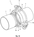
- FIG. 1A and FIG. 1B Shown in FIG. 1A and FIG. 1B is the formation of a pipe joint 10 between first and second pipe segments 12, 14 using a preferred preassembled coupling 100.
- the coupling 100 includes a plurality of interior groove engagement surfaces for engaging the outer surface of the pipe segments 12, 14 and a gasket member 400 for forming a fluid tight seal about the pipe joint 10.
- FIG. 1A shows the coupling 100 in an open configuration with a first pipe segment 12 inserted into first receiving side 100a of the preferred coupling 100 with a second pipe segment 14 in position for insertion into a second receiving side 100b of the coupling 100.
- FIG. 1B each of the first and second pipe segments 12, 14 are inserted within the coupling 100 in an end-to-end relationship and the coupling is placed into a closed configuration.
- the preferred coupling 100 provides a preassembled connection fitting having a first configuration for locating the two pipe segments 12, 14 in an end-to-end relationship and a second configuration for forming a fluid tight seal between the pipe segments in the end-to-end relationship.
- the coupling 100 is preferably configured for joining grooved-end pipe segments.
- the pipe segment 14 includes a circumferential groove 14a and pipe segment 12 includes a corresponding circumferential groove 12a.
- the interior engagement surfaces 106 are configured to engage the circumferential grooves 12a, 14a to prevent axial separation of the pipe segments, as seen for example in FIG. 5B .
- the interior engagement surfaces 106 of the coupling 100 may engage alternatively configured pipe segment ends.
- the coupling 100 may be used to join shoulder pipe as seen for example in FIGS. 7A and 7B .
- the interior pipe engagement surfaces may define a geometry to engage plain end pipe in a frictional and/or mechanical engagement to prevent axial separation.
- the interior engagement surface 106 may define mechanical teeth for gripping plain end pipe (not shown).
- each receiving end 100a (not shown), 100b of the coupling assembly 100 includes a plurality of pipe engagement surfaces 106 for preferably engaging an outer surface of a pipe segment 12, 14 received in the receiving end 100a, 100b in order to hold the pipe segments 12, 14 in an end-to-end relationship to form the pipe joint 10.
- each receiving end 100a, 100b includes a first pipe engagement surface 106a and a second engagement surface 106b configured to pivot with respect to one another.
- Each receiving end 100a, 100b preferably includes a third engagement surface 106c which cooperates with the other engagement surfaces 106a, 106b to define a substantially closed form interior space 108 of the preassembled coupling 100.
- the coupling 100 further preferably provides for a preferred arrangement of components to locate and space the third engagement surface 106c relative to the first and second groove engagement surfaces 106a, 106b in order to form and seal the pipe joint 10.
- the preferred arrangement of components tension the assembly 100 so as to pivot the first and second engagement surfaces 106a, 106b with respect to one another to locate and space the engagement surfaces 106a, 106b, 106c with respect to one another.
- the coupling preferably has a first state or configuration to maximize the size or area defined by the interior space 108 in the open configuration of the coupling 100 to allow insertion of the pipe segment 12, 14 into the interior space 108.
- the coupling 100 also preferably has a second state or configuration to minimize the size or area of the interior space 108 in the closed configuration of the coupling 100 to enclose the coupling 100 about the pipe segment to form a preferably fluid tight seal about the pipe joint 10.
- a preferred embodiment of the coupling assembly 100 includes a plurality of identical housing segments 110, each of which defines or includes the arcuate pipe engagement surfaces 106.
- the preferred embodiment of the coupling 100 includes three housing segments 110a, 110b, 110c which are interconnected to one another in an end-to-end relationship.
- Each of the preferred housing segments 110 have a first end pad 112 and a second end pad 114 with a housing body 116, and more preferably an arcuate housing body, extending between the first and second end pads 112, 114.
- the housing body 116 of each segment 110 defines a portion of the receiving end face 100a, 100b of the coupling 100 and further provides the arcuate engagement surfaces 106 for engaging the outer surface of an inserted pipe segment.
- Each arcuate pipe engagement surface 106 defines a radius of curvature R from a center of curvature C which is about equal to the radius of curvature defined by the outer surface of the pipe segments 12, 14 to be inserted into coupling 100. More preferably, the radius R is about equal to the radius defined by the nominal groove diameter of a grooved-end pipe segment to be inserted into the coupling 100.
- the radius of curvature R may have some variability with the radius of curvature defined by the circumferential grooves 12a, 14a or other portion of the pipe segments 12, 14 provided that the engagement surfaces 106 of the housing segment 110 can properly engage the outer surface of the pipe segments 12, 14 to form the pipe joint as described herein. For the preferred embodiment shown in FIG.
- each of the three, preferably identical, housing segments 110a, 110b, 110c and their corresponding arcuate surfaces 106a, 106b, 106c define a radius of curvature Ra, Rb, Rc from corresponding centers Ca, Cb, Cc, in which the radii are preferably equal to one another for engaging a nominally circular pipe segment and more preferably engaging its circumferential groove.
- the arcuate surfaces 106a, 106b, 106c are preferably continuous over the arc length of the housing segment 110.
- the arcuate surfaces 106a, 106b, 106c preferably extend continuously 120 degrees about the center of curvature Ca, Cb, Cc.
- the arcuate surfaces 106a, 106b, 106c may be discontinuous or segmented over the length of the housing segments 110a, 110b, 110c provided each segment defines the same radius of curvature over the housing segment from the common center of curvature.
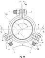
- the radial spacing of the first, second and third arcuate surfaces 106a, 106b, 106c is maximized in the open configuration of the coupling 100 for receipt of a pipe segment. Because the arcuate surfaces 106a, 106b, 106c preferably have an equal or common radius of curvature Ra, Rb, Rc, their centers of curvature Ca, Cb, Cc are correspondingly spaced apart (as graphically shown in FIG. 2A for illustrative purposes). The radial spacing of the first, second and third arcuate surfaces 106a, 106b, 106c is minimized in the closed configuration of the coupling 100 for engagement with and about the circumferential grooves 12a, 14a of pipe segments 12, 14.
- the centers of curvature Ca, Cb, Cc are substantially coaxially aligned at C (as graphically shown in FIG. 2B ) with the central axis defined by the circumferential groove or pipe segment.
- the radii of curvatures Ra, Ra, Rc being constant or remaining the same in each of the open and closed configurations of the preferred coupling 100, there is no deformation in the housing segments 110a, 110b, 110c in the transition from the open to the closed configuration of the preferred preassembly 100.
- the preferred joint assembly is formed without deformation of the pipe segments 12, 14 such that they retain their same outer diameter in each of the open and closed configurations of the coupling 100.
- the housing segments 110 are joined end pad 112 to end pad 114.
- Each of the first and second end pads 112, 114 includes a through bore 118 for receiving a bolt assembly to join the housing segments 110a, 110b together.
- the preferred coupling 100 includes the first housing segment 110a coupled to the second housing segment 110b by a first bolt assembly 200 and more preferably by a gap setting bolt assembly 200 which permits the housing segments 110a, 110b and their arcuate surfaces 106a, 106b to pivot relative to one another.
- the first and second end pads 112c, 114c of the third housing segment 110c are joined respectively to the second end pad 114b of the second housing segment 110b and the first end pad 112a of the first housing segment 110a.
- each of the joined end pad pairs 112c, 114b, 114c, 112a is a bolt assembly 300a, 300b, which locates and spaces the third arcuate surface 106c with respect to the first and second arcuate surfaces 106a, 106b and further preferably applies a force to pivot the first and second arcuate surfaces 106a, 106b with respect to one another.
- the gap setting bolt assembly 200 defines a set or fixed gap or range of separation between the second end pad 114a of the first housing segment and the first end pad 112b of the second housing segment. More preferably gap setting bolt assembly 200 defines the outer angular range ⁇ and internal angular range ⁇ , each of which defines an included angle about a common pivot point P formed between and along the first and second end pads 114a, 112b.
- the first and second housing segments 110a, 110b are pivoted away from one another such that the outer angular range ⁇ is minimized and the internal angular range is maximized.
- the first and second housing segments 110a, 110b are pivoted toward one another such that the outer angular range ⁇ is maximized and the internal angular range ⁇ is minimized.
- the pivot between the first and second housing segments 110a, 110b is controlled by the second and third bolt assemblies 300a, 300b.
- the bolts 300a, 300b are arranged so as to maximize the respective gaps or spacing between the end pads 112a, 114c of the first and third housing segments 110a, 110c and between the end pads 112c, 114b of the second and third housing segments 110b, 110c.
- the separation of the end pads 112a, 114c, 112c, 114b by each of the bolt assemblies 300a, 300b further preferably causes the first and second housing segments 110a, 110b into contact at their joined end pads 114a, 112b to define the pivot point P such that the housing segments 110a, 110b pivot away from one another about the pivot point thereby minimizing the outside radial angle ⁇ and maximizing the internal radial angle ⁇ .
- the bolt assemblies 300a, 300b are tightened so as to bring the end pads 112c, 114c of the third housing segment 110c into contact with the corresponding end pads 112a, 114b of the first and second housing segments 110a, 110b.
- Continued tightening of the bolt assemblies 300a, 300b in the preferred assembly 100 causes the first and second housing segments 110a, 110b to pivot toward one another about the pivot point P thereby maximizing the outside radial angle ⁇ MAX and minimizing the internal radial angle ⁇ MIN as seen, for example, in the closed configuration of FIG. 2B in which the first and second housing segments 110a, 110b are secured so as not to pivot with respect to one another.
- the bolt assemblies 300 preferably include a bolt portion 302 and nut portion 304.
- the bolt assemblies are preferably off-the-shelf fasteners.
- the bolt portion 302 can include an external geometry to prevent the bolt from spinning within the bore 18 of the end pads 112, 114.
- the preassembled coupling 100 and its end pads 112, 114 are preferably oriented about the pipe joint 10 such that the end pads 112, 114 angle the bolt assemblies 300a, 300b with respect to a plane P1 extending parallel to the gap setting bolt axis A-A such that the nuts are located beneath the plane P1 and the bolt assemblies 300a, 300b are angled toward one another to define an included angle ⁇ preferably of about 60 degrees between the bolt axes of the bolt assemblies 300.
- the term "about” is understood as within a range of normal tolerance in the art, for example within 2 standard deviations of the mean.
- the location and orientation of the bolt assemblies 300a, 300b can facilitate their installation and adjustment by making the nuts easy to access and adjust relative to the pipe segments 12, 14 for the coupling installer.
- the orientation and location of the bolt assemblies and in particular the nuts 304 make it easier for an overhead installation by positioning the nuts 304 beneath the plane P and by placing them in close proximity to one another due to the preferred angular orientation between the bolt axes.
- FIG. 3A Shown in FIG. 3A is a cross-sectional detailed view of the preferred pivoted connection 102 between the first and second housing segments 110a, 110b.
- the first and second end pads 112, 114 for each housing segment 110 of the coupling are similarly configured, having through bores 118 for receipt of either one of the gap setting bolt 200 or the second and third bolt assemblies 300.
- the through bores 118 and bolt assemblies 200, 300 are preferably configured so as to minimize or eliminate spinning or rotation of the bolt assemblies 200, 300 within the bore 118.
- the through bore 118 can have a non-circular geometry, such as for example oval, and the bolt of the bolt assembly can have a corresponding outer geometry to provide for an engagement that minimizes or eliminates relative rotation.
- An exemplary end pad bore and bolt geometry is shown and described with respect to FIG. 6C of U.S. Patent Application Publication No. 2012/0256418 .
- each of the end pads 112, 114 include or define a contact surface 120 which extends from the peripheral edge of the end pad toward the arcuate surface 106.
- the contact surface 120a of the first housing segment 110a faces the contact surface 120b of the second housing segment 110b in the preferred preassembled arrangement.
- the preferred gap setting bolt 200 defines a gap W in which the joined end pads are held in proximity to one another. More preferably, the end pads 114a, 112b are configured and joined together such that their contact surfaces 120a, 120b contact one another at a pivot point P so as to define the included outer and inner radial angles ⁇ , ⁇ over which the housing segments 110a, 110b pivot with respect to one another.
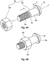
- the bolt assembly preferably includes a shank portion 202a and a nut portion 202b.
- the shank portion 202a defines a shank axis A-A and preferably includes an upper shank portion 204a and a lower externally threaded shank portion 204b for threaded engagement with the internal nut portion 202b using a suitable thread specification, for example, those used in known grooved coupling assemblies, i.e., 1/2"-13UNC-28.
- the upper shank portion 204a preferably defines an outer or peripheral geometry for corresponding engagement with the through bore 118 of the end pads 112, 114 such that the bolt assembly 200 will not spin within the through bore.
- the upper shank portion 204a further preferably defines an axial length L which is sufficient to extend through the coupled through bores 118a, 118b in the closed configuration of the coupling 100.
- the axial length L is about equal to the maximum thickness of two end pads 112, 114 in contact face-to-contact face 120 engagement.
- the axial length of the upper shank portion 204a is preferably defined by spacing between a shoulder 206 and an enlarged bolt head 208 of the shank portion 204.
- the shoulder 206 defines a surface transition between the upper and lower shank portions 204a, 204b and is more preferably angled with respect to the bolt axis A-A.
- the shoulder 206 presents a limit or obstruction to the nut portion 202b and its threaded engagement so as ensure that the assembly 200 provides for the desired gap W over which the housing segments 110a, 110b may pivot with respect to one another.
- FIGS. 3B and 3C are alternate embodiments of the gap setting bolt assembly 200.
- a gap setting bolt assembly 200' includes a shank portion 200'a and nut portion 200'b.
- the nut portion 200'b includes a first fixed nut 210a and an adjustable nut 210b in which the fixed nut 210a is fixed along the shank portion 200'a so as to set the width W and limit the threaded engagement of the adjustable nut 210b.
- FIG. 3C is another embodiment of a gap setting bolt assembly 200" in which the nut portion 200"b includes a cap or closed end nut which defines an internal thread of limited length LL. The closed end of the nut limits the threaded engagement between the nut cap and the shank portion 200"a so as to define the desired gap W in the preassembled coupling 100.
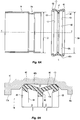
- FIGS. 5A and 5B Shown in FIGS. 5A and 5B is the formation of pipe joint 10 defining the central joint axis X-X using the preferred preassembled coupling 100.
- the preferred coupling 100 is preferably symmetrical about the axis Y-Y which defines a bisecting plane BP and bisects the coupling 100 perpendicular to the joint axis X--X.
- Shown particularly in FIG. 5A is a cross-sectional view of the coupling 100 showing the first housing segment 110a and the third housing segment 110c in their open configuration. Inserted in each receiving end 100a, 100b is a pipe segment 12, 14 for formation of the preferred joint.
- the coupling 100 extends across the end-to-end pipe junction so that the arcuate surfaces 106a, 106c at each receiving end 100a, 100b is aligned with the circumferential grooves 12a, 14a of the pipe segments 12, 14.
- the open configuration of the preassembled coupling 100 provides sufficient clearance for insertion of the pipe segments 12, 14; and more particularly, provides a housing for a pipe joint gasket 400 and insertion of the pipe joint segments 12, 14.
- Shown in FIG. 5B is the coupling 100 in its preferred closed configuration with the arcuate surfaces 106a, 106c engaged with the circumferential grooves 12a, 14a of the pipe segments 12, 14.
- the closed configuration of the preassembled coupling 100 collapses the interior surface of the housing segments 110a, 110b about the pipe segments 12, 14 such that the gasket 400 is compressed, as seen in FIG. 5B so as to form the sealed pipe joint.
- FIG. 7B shown is an alternate pipe joint arrangement 10' in which the coupling 100 joins first and second shoulder pipe segments 12', 14'.
- the gasket 400 is preferably a continuous annular member defining a central axis for axial alignment with the joint axis X-X.
- the gasket 400 includes an inner surface 400a and an outer surface 400b.
- the gasket is preferably formed symmetrically about a bisecting axis C--C which extends substantially perpendicularly to the joint axis X-X and parallel to the joint bisecting axis Y-Y (shown in FIG. 5A ).
- the inner surface preferably includes a pair of sealing lips or members 406 disposed about the bisecting axis C-C providing a surface for sealing engagement with the outer surface of the pipe segments 12, 14 in the closed configuration of the assembly 100 as seen for example in FIG. 5B .
- the sealing lips 406 are preferably angled or tapered inwardly toward the central axis C-C so as to terminate at an interior edge or tip 404 and present a frustroconical surface defining an internal diameter DIA.
- the preferred open configuration of the coupling 100 supports the gasket 400 for receipt of pipe segments 12, 14.
- the internal diameter DIA is preferably greater than the maximum outer diameter OD of the pipe segments 12, 14, as seen in FIG. 6A or the outer diameter OD' of an alternatively configured pipe, such as for example, shoulder pipe segments 12', 14' as seen in FIG. 7A .
- the gasket member 400 can provide a resistance support for separating the pipe engagement surfaces 106 of the coupling 100 for receipt of the pipe segments 12, 14.
- the gasket member 400 is a preferably resilient member having an uncompressed state in which the sealing lips 406 define a sufficiently large internal diameter DIA. for receipt of the pipe segments.
- the gasket can have a sufficient resilience and/or the outer surface 400b can define a sufficiently large outer diameter of the gasket 400 to radially support the housing segments 110 such that their arcuate surfaces 106a, 106b (not shown, 106c) are spaced about the gasket 400 to permit insertion of the pipe segments 12, 14 into the interior space 108 of the preassembled coupling 100.
- the internal surface of the housing segments 110 preferably defines an internal cavity 130 between the pipe engagement surfaces 106 at cavity depth that engages the outer surface 400b of the gasket 400 such that the arcuate surfaces 106 of the housing segments in the preassembled coupling 100 are spaced apart from one another to allow for insertion of the pipe segments 12, 14 into the interior space of the coupling 100.
- a central rib 408 aligned with the bisecting axis C-C.
- the central rib 408 extends radially toward the central axis X-X so as to provide buffer between the pipe segments 12, 14 when in their end-to-end relationship upon insertion into the preassembled coupling 100.
- the outer surface 400b defines a pair of shoulders 402 about the bisecting axis C-C.
- the shoulders 402 define the maximum diameter of the gasket 400. Accordingly the diameter of the outer surface 400b preferably becomes smaller toward the bisecting axis Y-Y.
- the gasket When housed within the preassembled coupling 100, the gasket is disposed within the cavities 130 defined by each housing segment 110a, 110b, 110c and its internal surface.
- the outer surface 400b and the shoulders 402 of the gasket 400 preferably engage the interior surfaces of the housing segments 110a, 110b, 110c in the open configuration of the preassembled coupling 100 so as to define a void 132 between the interior surface and the outer surface 400b of the gasket 400 as seen in FIG. 6B .
- the interior surface of the housing segments 110a, 110b, 110c preferably define a cavity depth so that in the closed configuration of the preassembled coupling 100, the gasket is compressed such that the sealing lips 406 fully engage the outer surface of the pipe segments to form a fluid tight seal as seen for example in FIG. 5B .
- Alternate internal housing (cavity) and gasket geometries or arrangements are shown in U.S. Patent Application Publication No. 2012/0256418 and U.S. Patent Application Publication No. 2012/0248767 .
- the preferred coupling 100 provides for a preassembly in which pipe segments 12, 14 can be inserted into the preassembly or alternatively the coupling 100 can be disposed over an end of the pipe segments 12, 14 as a preassembly.
- each of the interior arcuate surfaces 106 are spaced from the central axis X-X, and the sealing lips 406 each define a minimum internal diameter DIA. to permit insertion or receipt of the pipe segments 12, 14 as shown in FIGS. 5A and 6A .
- each of the three housing segments are spaced radially from the central axis at a greater distance than the radial distance defined between the gasket sealing lip tip 404 and the central axis so as to allow for insertion of pipe segments 12, 14 into the assembly and form the end-to-end relationship of the pipe joint.
- the closed configuration spaces the housing segments 110 about the pipe segments 12, 14 so as to engage the outer surface of the pipe segments 12, 14 and more preferably compress the internal gasket 400 to form a fluid tight seal about the joint 10.
- the pipe engagement surfaces 106 are configured such that there is no deformation in the piping or housing segments in the transition from the first to the second state or configuration of the coupling 100.
Landscapes
- Engineering & Computer Science (AREA)
- General Engineering & Computer Science (AREA)
- Mechanical Engineering (AREA)
- Physics & Mathematics (AREA)
- Fluid Mechanics (AREA)
- Branch Pipes, Bends, And The Like (AREA)
- Joints With Sleeves (AREA)
Claims (12)
- Vormontierte Rohrkupplung (100) mit einer ersten Konfiguration zum Gestatten eines Einführens von Rohrsegmenten (12, 14) in einen Innenraum (108) der Kupplung (100) und einer zweiten Konfiguration zum Bilden einer fluiddichten Dichtung um die eingeführten Rohrsegmente (12, 14) herum, wobei die vormontierte Rohrkupplung Folgendes umfasst:ein erstes Gehäusesegment (110a) mit einer ersten Rohreingriffsfläche (106a), die einen Krümmungsradius (Ra) von einer ersten Krümmungsmitte (Ca) aufweist, wobei das erste Gehäusesegment (110a) ein erstes Paar Endglieder (112a, 114a) aufweist, wobei die erste Eingriffsfläche (106a) zwischen dem ersten Paar Endglieder (112a, 114a) angeordnet ist;ein zweites Gehäusesegment (110b) mit einer zweiten Rohreingriffsfläche (106b), die einen zweiten Krümmungsradius (Rb) von einer zweiten Krümmungsmitte (Cb) aufweist, wobei das zweite Gehäusesegment (110b) ein zweites Paar Endglieder (112b, 114b) aufweist, wobei die zweite Eingriffsfläche (106b) zwischen dem zweiten Paar Endglieder (112b, 114b) angeordnet ist;ein drittes Gehäusesegment (110c) mit einer dritten Rohreingriffsfläche (106c), die einen dritten Krümmungsradius (Rc) von einer dritten Krümmungsmitte (Cc) aufweist, wobei das dritte Gehäusesegment (110c) ein drittes Paar Endglieder (112c, 114c) aufweist, wobei die dritte Eingriffsfläche (106c) zwischen dem dritten Paar Endglieder (112c, 114c) angeordnet ist, wobei der erste, der zweite und der dritte Radius (Ra, Rb, Rc) identisch sind,eine erste Bolzenanordnung (200), die eine erste Bolzenachse definiert, wobei die erste Bolzenanordnung (200) ein Endglied (114a) des ersten Gehäusesegments (110) mit einem Endglied (112b) des zweiten Gehäusesegments (110b) koppelt, um einen Drehpunkt (P) zu definieren, um den die erste und die zweite Rohreingriffsfläche (106a, 106b) bezüglich einander schwenken;ein ringförmiges Dichtungsglied (400), das eine mittlere Achse definiert; undeine zweite Bolzenanordnung (300a) und eine dritte Bolzenanordnung (300b) zum Positionieren der ersten, der zweiten und der dritten Rohreingriffsfläche (106a, 106b, 106c) um das Dichtungsglied (400) in der ersten Konfiguration, um den Innenraum (108) der Kupplung (100) zum Einführen der Rohrsegmente (12, 14) zu definieren, wobei die zweite und die dritte Bolzenanordnung (300a, 300b) die erste, die zweite und die dritte Rohreingriffsfläche (106a, 106b, 106c) in der zweiten Konfiguration um das Dichtungsglied (400) herum positionieren, derart, dass die erste, die zweite und die dritte Rohreingriffsfläche (106a, 106b, 106c) die Außenfläche der Rohrsegmente (12, 14) in Eingriff nehmen und das Dichtungsglied (400) um die Außenfläche komprimieren, um eine fluiddichte Dichtung zu bilden, wobei die zweite Bolzenanordnung (300a) eine zweite Bolzenachse definiert und die dritte Bolzenanordnung (300b) eine dritte Bolzenachse definiert, wobei die zweite Bolzenanordnung (300a) das andere Endglied (112a) des ersten Gehäusesegments (110a) mit einem Endglied (114a) des dritten Gehäusesegments (110c) zusammenfügt, wobei die dritte Bolzenanordnung (300b) das andere Endglied (114b) des zweiten Gehäusesegments (110b) mit dem anderen Endglied (112a) des dritten Gehäusesegments (110c) zusammenfügt, wobei die zweite und die dritte Bolzenanordnung (300a, 300b) bezüglich einander so ausgerichtet sind, dass die zweite und die dritte Bolzenachse jeweils einen zwischen der zweiten und der dritten Bolzenachse eingeschlossenen spitzen Winkel definieren,wobei in der ersten Konfiguration die erste, die zweite und die dritte Krümmungsmitte (Ca, Cb, Cc) voneinander beabstandet sind und in der zweiten Konfiguration die erste, die zweite und die dritte Krümmungsmitte (Ca, Cb, Cc) koaxial ausgerichtet sind, wobei der erste, der zweite und der dritte Radius (Ra, Rb, Rc) sowohl in der ersten als auch in der zweiten Konfiguration gleich sind, dadurch gekennzeichnet, dassdie erste Bolzenanordnung (200) einen Schaft (202a) und eine Mutter (202b) aufweist, wobei der Schaft (202a) einen oberen Teil (204a), der einen Bolzenkopf enthält, und einen unteren Gewindeteil (204b) aufweist, wobei die Mutter (202b) auf dem unteren Gewindeteil (204b) angeordnet ist, wobei jedes Endglied (112, 114) eine Kontaktfläche (120) und eine Durchgangsbohrung aufweist, wobei sich der Schaft (202a) durch die Durchgangsbohrungen jedes Endglieds (112, 114), die durch die erste Bolzenanordnung (200) zusammengefügt sind, erstreckt, derart, dass sich ihre Kontaktflächen (120) berühren, um den Drehpunkt (P) zu definieren, wobei der Drehpunkt (P) entlang den Kontaktflächen (120) dahingehend positioniert ist, einen äußeren Radialwinkel (α) und einen inneren Radialwinkel (β) um den Drehpunkt (P) zu definieren, in dem die erste und die zweite Eingriffsfläche (120) bezüglich einander schwenken, wobei in der ersten Konfiguration der äußere Radialwinkel (α) minimiert ist und der innere Radialwinkel (β) maximiert ist und in der zweiten Konfiguration der äußere Radialwinkel (α) maximiert ist und der innere Radialwinkel (β) minimiert ist.
- Vormontierte Rohrkupplung (100) nach Anspruch 1, wobei der spitze Winkel zwischen der zweiten und der dritten Bolzenachse sechzig Grad beträgt.
- Vormontierte Rohrkupplung (100) nach Anspruch 1, wobei die zweite und die dritte Bolzenanordnung (300a, 300b) jeweils einen Bolzen (302) und eine Mutter (304) enthalten, wobei der Bolzen (302) einen Bolzenkopf mit einem Gewindeschaft aufweist, wobei die Mutter (304) auf dem Gewindeschaft angeordnet ist, wobei sich die erste Bolzenachse in der zweiten Konfiguration parallel zu einer durch die erste, die zweite und die dritte Krümmungsmitte (Ca, Cb, Cc), die aufeinander ausgerichtet sind, verlaufenden Ebene erstreckt, wobei die zweite und die dritte Bolzenanordnung (300a, 300b) gegenüber der ersten Bolzenanordnung (200) auf einer Seite der Ebene angeordnet sind, wobei die Bolzenköpfe der zweiten und der dritten Bolzenanordnung (300a, 300b) zwischen der Ebene und den Muttern (304) der zweiten und der dritten Bolzenanordnung (300a, 300b) angeordnet sind.
- Vormontierte Rohrkupplung (100) nach Anspruch 1, wobei die Rohrsegmente (12, 14) eine Umfangsnut (12a, 14a) aufweisen, die erste, die zweite und die dritte Rohreingriffsfläche (106a, 106b, 106c) in der zweiten Konfiguration der Kupplung (100) die Umfangsnut (12a, 14a) in Eingriff nehmen, wobei die Umfangsnut (12a, 14a) einen Außendurchmesser des Rohrsegments (12, 14), der in der ersten sowie in der zweiten Konfiguration der gleiche ist, definiert.
- Vormontierte Rohrkupplung (100) nach Anspruch 1, wobei das ringförmige Dichtungsglied (400) eine Dichtlippe (406) aufweist, wobei sich die Dichtlippe (406) in der ersten Konfiguration um die mittlere Achse erstreckt, um einen Innendurchmesser der Dichtung (400) zu definieren, der größer als ein Außendurchmesser des Rohrsegments ist.
- Vormontierte Rohrkupplung (100) nach Anspruch 1, wobei die drei Gehäusesegmente (110a, 110b, 110c) in der ersten Konfiguration um die ringförmige Dichtung (400) herum positioniert sind, derart, dass ein Innendurchmesser der Dichtung (400) größer als ein Außendurchmesser eines Rohrsegments (12, 14) ist, wobei die Rohreingriffsflächen (106) um die mittlere Achse herum positioniert sind, um ein Einführen des Rohrsegments (12, 14) in die Dichtung (400) zu gestatten; und
wobei die drei Gehäusesegmente (110a, 110b, 110c) in der zweiten Konfiguration radial um die ringförmige Dichtung (400) herum positioniert sind, derart, dass die Dichtung (400) komprimiert wird und eine Dichtlippe (406) einen Teil der Außenfläche des Rohrs in Eingriff nimmt, um eine fluiddichte Dichtung zu bilden, wobei die Rohreingriffsflächen (106) um die mittlere Achse herum positioniert sind, um einen anderen Teil der Außenfläche des Rohrsegments (12, 14) in Eingriff zu nehmen, wobei der Außendurchmesser des Rohrsegments (12, 14) in der zweiten Konfiguration gleich dem Außendurchmesser des Rohrs in der ersten Konfiguration ist. - Verfahren zum Bilden einer Rohrverbindung mit einer vormontierten Rohrkupplung (100) nach Anspruch 1, die drei identische Gehäusesegmente (110) aufweist, welche Ende an Ende miteinander verbunden sind, um eine ringförmige Rohrdichtung (400) aufzunehmen und ein Paar Endflächen der vormontierten Kupplung (100) zu bilden, die um die Rohrdichtung (400) herum angeordnet sind, wobei das Verfahren Folgendes umfasst:Positionieren der drei identischen Gehäusesegmente (106) um die Rohrdichtung (400) herum in einer ersten Konfiguration, derart, dass ein Innendurchmesser der Dichtung (400) größer als ein Außendurchmesser eines Rohrsegments (12, 14) zur Aufnahme eines Rohrsegments (12, 14) ist, wobei der Innendurchmesser durch eine Innenfläche (400) der Dichtung definiert wird, die eine Dichtlippe (406) enthält, welche eine mittlere Achse umschreibt, wobei jedes Gehäusesegment ein bogenförmiges Segment mit einem Paar Endglieder (112, 114) aufweist, die um das bogenförmige Segment herum angeordnet sind, wobei das bogenförmige Segment ein Paar Rohreingriffsflächen (106) enthält, die sich von einem Endglied (112) zu dem anderen Endglied (114) parallel zueinander erstrecken, wobei das Gehäusesegment (110) eine Innenfläche aufweist, die einen Hohlraum zwischen den Rohreingriffsflächen (106) zur Aufnahme eines Teils der ringförmigen Rohrdichtung (400) definiert, wobei jede Rohreingriffsfläche (106) einen Krümmungsradius von einer Krümmungsmitte aufweist, wobei die Krümmungsradien der drei Gehäusesegmente (110) identisch sind, wobei das Positionieren der drei Gehäusesegmente (110) in der ersten Konfiguration ein Voneinanderwegschwenken eines ersten Gehäusesegments (110a) und eines zweiten Gehäusesegments (110b) derart, dass die Krümmungsmitten um die mittlere Achse herum beabstandet sind, umfasst;Positionieren der drei Gehäusesegmente (110) um die Rohrdichtung (400) herum in einer zweiten Konfiguration, derart, dass die Rohrdichtung (400) komprimiert wird, so dass die Dichtlippe (406) einen Teil der Außenfläche des Rohrs in Eingriff nimmt, um eine fluiddichte Dichtung zu bilden, wobei die Rohreingriffsflächen (106) um die mittlere Achse herum positioniert werden, um einen anderen Teil der Außenfläche des Rohrsegments (12, 14) in Eingriff zu nehmen; undAufrechterhalten der Krümmungsradien der Eingriffsflächen und des Außendurchmessers des Rohrsegments (12, 14) derart, dass sie in der ersten sowie in der zweiten Konfiguration die gleichen sind.
- Verfahren nach Anspruch 7, wobei das Positionieren der drei Gehäusesegmente (110) in der ersten Konfiguration Schwenken des ersten und des zweiten Gehäusesegments (110a, 110b) über einen durch eine ein Endglied (112) des ersten Gehäusesegments (110a) mit einem Endglied (114) des zweiten Gehäusesegments (110b) koppelnde erste Bolzenanordnung (200) definierten Winkelbereich umfasst, wobei jedes Endglied eine Kontaktfläche und eine Durchgangsbohrung aufweist, wobei sich der Schaft durch die Durchgangsbohrungen jedes Endglieds (112, 114), die durch die erste Bolzenanordnung (200) zusammengefügt sind erstreckt, derart, dass sich ihre Kontaktflächen berühren, um den Drehpunkt (P) zu definieren, wobei der Drehpunkt (P) entlang den Kontaktflächen dahingehend positioniert ist, einen äußeren Radialwinkel (α) und einen inneren Radialwinkel (β) um den Drehpunkt (P) zu definieren, in dem die erste und die zweite Eingriffsfläche (106) bezüglich einander schwenken, wobei in der ersten Konfiguration der äußere Radialwinkel (α) minimiert ist und der innere Radialwinkel (β) maximiert ist.
- Verfahren nach Anspruch 8, wobei das Positionieren der drei Gehäusesegmente (110) in der zweiten Konfiguration Zueinanderschwenken des ersten und des zweiten Gehäusesegments (110a, 110b) über einen durch eine Bolzenanordnung (200) definierten Winkelbereich umfasst.
- Verfahren nach Anspruch 9, wobei das Positionieren der drei Gehäusesegmente (110) in irgendeiner der ersten und der zweiten Konfiguration Folgendes umfasst:Einstellen einer eine zweite Bolzenachse definierenden zweiten Bolzenanordnung (300a) und einer eine dritte Bolzenachse definierenden dritten Bolzenanordnung zum Positionieren des dritten Gehäusesegments (110c) bezüglich des ersten und des zweiten Gehäusesegments (110a, 110b); undAusrichten der zweiten und der dritten Bolzenachse zum Definieren eines zwischen der zweiten und der dritten Bolzenachse eingeschlossenen spitzen Winkels;wobei das Einstellen Zugreifen auf eine Mutter einer der zweiten und dritten Bolzenanordnung (300a, 300b), die auf einer Seite einer parallel zu der ersten Bolzenachse verlaufenden und die mittlere Achse durchquerenden Ebene angeordnet ist, umfasst, undwobei ferner die zweite und die dritte Bolzenanordnung (300a, 300b) einen zwischen der Mutter und der Ebene angeordneten Bolzenkopf enthalten.
- Verfahren nach Anspruch 10, wobei Ausrichten der zweiten und der dritten Bolzenachse den eingeschlossenen spitzen Winkel als sechzig Grad definiert.
- Verfahren nach Anspruch 9, wobei das Positionieren der Gehäusesegmente (110) in der zweiten Konfiguration umfasst, dass die Rohreingriffsflächen (106) eine Umfangsnut (12a, 14a) des Rohrsegments (12, 14) in Eingriff nehmen.
Applications Claiming Priority (2)
| Application Number | Priority Date | Filing Date | Title |
|---|---|---|---|
| US201361774409P | 2013-03-07 | 2013-03-07 | |
| PCT/EP2014/054377 WO2014135649A1 (en) | 2013-03-07 | 2014-03-06 | Three piece pipe coupling |
Publications (2)
| Publication Number | Publication Date |
|---|---|
| EP2964989A1 EP2964989A1 (de) | 2016-01-13 |
| EP2964989B1 true EP2964989B1 (de) | 2018-12-26 |
Family
ID=50238382
Family Applications (1)
| Application Number | Title | Priority Date | Filing Date |
|---|---|---|---|
| EP14708537.7A Active EP2964989B1 (de) | 2013-03-07 | 2014-03-06 | Dreiteilige rohrkupplung |
Country Status (4)
| Country | Link |
|---|---|
| US (1) | US10571054B2 (de) |
| EP (1) | EP2964989B1 (de) |
| TW (1) | TWI700452B (de) |
| WO (1) | WO2014135649A1 (de) |
Families Citing this family (9)
| Publication number | Priority date | Publication date | Assignee | Title |
|---|---|---|---|---|
| WO2017173045A1 (en) * | 2016-03-30 | 2017-10-05 | Hyrda-Zorb | Insulated riser clamp |
| CN106439313B (zh) * | 2016-08-01 | 2019-01-22 | 杨顺立 | 多瓣斜平面卡箍及其管连接件 |
| US11378208B2 (en) | 2016-12-14 | 2022-07-05 | ASC Engineered Solutions, LLC | Pipe couplings |
| US10641419B2 (en) | 2016-12-14 | 2020-05-05 | Anvil International, Llc | Pipe coupling with closed ring |
| CN110678686A (zh) * | 2017-05-30 | 2020-01-10 | 泰科消防产品有限合伙公司 | 带有可手动操纵段的预装配式管联接器 |
| EP3631270B1 (de) | 2017-05-30 | 2023-09-20 | Tyco Fire Products LP | Vormontierte rohrkupplung mit einer einführgrenze zur axialen aufnahme von rohrenden |
| US11079048B2 (en) * | 2018-06-13 | 2021-08-03 | TKO Clamping Systems, LLC | Clamping devices, systems and methods |
| US11796095B2 (en) * | 2021-09-23 | 2023-10-24 | ASC Engineered Solutions, LLC | Pipe fitting with positive installation indicator |
| WO2025017563A1 (en) * | 2023-07-20 | 2025-01-23 | Crithmun Industries Ltd. | Mechanical pipe coupling for metallic pipes |
Family Cites Families (25)
| Publication number | Priority date | Publication date | Assignee | Title |
|---|---|---|---|---|
| FR618146A (fr) * | 1926-06-26 | 1927-03-03 | Alsacienne Constr Meca | Procédé d'assemblage pour tuyaux à brides |
| GB305609A (en) * | 1927-11-07 | 1929-02-07 | Vickers Ltd | Improvements in or relating to the joints of pipes or other vessels adapted to withstand fluid pressure |
| GB570913A (en) * | 1943-12-20 | 1945-07-27 | George Taylor | Improvements in the joining of pipes |
| US2752173A (en) * | 1952-06-02 | 1956-06-26 | Victaulic Co Of America | Flexible or rigid joint pipe couplings |
| US2710891A (en) * | 1953-10-26 | 1955-06-14 | American Telephone & Telegraph | Telegraph service board circuits |
| BE758895A (fr) * | 1970-04-27 | 1971-05-13 | Equip Speciaux Pour L Aviat | Dispositif pour la fixation d'un tuyau flexible sur un tube ou un raccord tubulaire rigide |
| SE361727B (de) * | 1970-05-13 | 1973-11-12 | K Robinson | |
| US4009403A (en) * | 1975-05-16 | 1977-02-22 | Westinghouse Air Brake Company | Low gain pulse generating circuit |
| US4408788A (en) * | 1981-09-23 | 1983-10-11 | Grinnell Fire Protection Systems Company, Inc. | Hingeable split pipe collar |
| US4471979A (en) * | 1982-03-15 | 1984-09-18 | Victaulic Company Of Canada Limited | Quick-connect coupling for thin-walled pipes |
| US4522434A (en) | 1982-04-23 | 1985-06-11 | Victaulic Company Of America | Multiple key segmented pipe coupling |
| GB8501099D0 (en) * | 1985-01-16 | 1985-02-20 | Fischer Castings Ltd George | Pipe collars |
| US4702500A (en) * | 1985-12-20 | 1987-10-27 | Victaulic Company Of America | Fire resistant seal |
| US4702499A (en) * | 1986-10-21 | 1987-10-27 | Victaulic Company Of America | Hingeable segmented pipe couplings |
| DE4009403C2 (de) * | 1990-03-23 | 1995-07-27 | Schott Glaswerke | Rohrleitungskupplung |
| US5505503A (en) * | 1992-07-31 | 1996-04-09 | Boivin; Sylvain | Conduit system |
| US6139069A (en) * | 1998-08-24 | 2000-10-31 | Central Sprinkler Corporation | Universal mechanical coupling with interfitting ends |
| US20030122377A1 (en) * | 2001-12-27 | 2003-07-03 | Northrop William F. | Tube coupling assembly |
| KR20060135838A (ko) * | 2004-03-26 | 2006-12-29 | 빅톨릭 컴패니 | 캠면을 갖는 키를 구비한 파이프 커플링 |
| US8038176B2 (en) * | 2009-08-11 | 2011-10-18 | Victaulic Company | Seal with rigid stop ring |
| WO2011056512A1 (en) | 2009-10-27 | 2011-05-12 | Tyco Fire Products Lp | Systems and methods for pipe couplings |
| AR078780A1 (es) | 2009-10-27 | 2011-11-30 | Tyco Fire Products Lp | Sistemas y metodos para acoplamientos articulados |
| US8621741B2 (en) * | 2009-11-30 | 2014-01-07 | Howard Hagiya | 4-way compression grooved coupling |
| TW201237296A (en) * | 2010-12-09 | 2012-09-16 | Lubrizol Advanced Mat Inc | Fluid handling assembly having a multilayered composite pipe employing a mechanical coupling and method of assembling the fluid handling assembly |
| US9039046B2 (en) * | 2012-01-20 | 2015-05-26 | Mueller International, Llc | Coupling with tongue and groove |
-
2014
- 2014-03-06 US US14/772,869 patent/US10571054B2/en active Active
- 2014-03-06 EP EP14708537.7A patent/EP2964989B1/de active Active
- 2014-03-06 WO PCT/EP2014/054377 patent/WO2014135649A1/en not_active Ceased
- 2014-03-07 TW TW103108022A patent/TWI700452B/zh not_active IP Right Cessation
Non-Patent Citations (1)
| Title |
|---|
| None * |
Also Published As
| Publication number | Publication date |
|---|---|
| WO2014135649A1 (en) | 2014-09-12 |
| TW201508197A (zh) | 2015-03-01 |
| US20160010771A1 (en) | 2016-01-14 |
| EP2964989A1 (de) | 2016-01-13 |
| US10571054B2 (en) | 2020-02-25 |
| TWI700452B (zh) | 2020-08-01 |
Similar Documents
| Publication | Publication Date | Title |
|---|---|---|
| EP2964989B1 (de) | Dreiteilige rohrkupplung | |
| US9169952B2 (en) | Systems and methods for hinge couplings | |
| US4639020A (en) | Self-adjusting pipe clamp and coupling | |
| US10100954B2 (en) | Systems and methods for pipe couplings | |
| US5104153A (en) | Fittings for pipe | |
| US10125907B2 (en) | Double hinge flex joint | |
| KR20220000914A (ko) | 프리미엄 연결부의 토크 숄더 | |
| JP2023544958A (ja) | 取り外し防止接続部材及び取り外し防止接続アセンブリ | |
| US9279501B2 (en) | Split seal for a shaft | |
| US9765927B2 (en) | Flange fitting | |
| KR101181420B1 (ko) | 구띠형 플랜지를 이용한 배관 이음 구조 | |
| EP3971460B1 (de) | Rohrhaltevorrichtung für rohrverbindung | |
| CN110500455A (zh) | 双卡套连接组件 | |
| BR112019017722B1 (pt) | Conexão tubular de rosca e método para a formação de uma conexão tubular de rosca | |
| HK1175833B (en) | Systems and methods for hinge couplings |
Legal Events
| Date | Code | Title | Description |
|---|---|---|---|
| PUAI | Public reference made under article 153(3) epc to a published international application that has entered the european phase |
Free format text: ORIGINAL CODE: 0009012 |
|
| 17P | Request for examination filed |
Effective date: 20151005 |
|
| AK | Designated contracting states |
Kind code of ref document: A1 Designated state(s): AL AT BE BG CH CY CZ DE DK EE ES FI FR GB GR HR HU IE IS IT LI LT LU LV MC MK MT NL NO PL PT RO RS SE SI SK SM TR |
|
| AX | Request for extension of the european patent |
Extension state: BA ME |
|
| DAX | Request for extension of the european patent (deleted) | ||
| STAA | Information on the status of an ep patent application or granted ep patent |
Free format text: STATUS: EXAMINATION IS IN PROGRESS |
|
| 17Q | First examination report despatched |
Effective date: 20171010 |
|
| GRAP | Despatch of communication of intention to grant a patent |
Free format text: ORIGINAL CODE: EPIDOSNIGR1 |
|
| STAA | Information on the status of an ep patent application or granted ep patent |
Free format text: STATUS: GRANT OF PATENT IS INTENDED |
|
| INTG | Intention to grant announced |
Effective date: 20180704 |
|
| RAP1 | Party data changed (applicant data changed or rights of an application transferred) |
Owner name: TYCO FIRE PRODUCTS LP |
|
| GRAS | Grant fee paid |
Free format text: ORIGINAL CODE: EPIDOSNIGR3 |
|
| GRAA | (expected) grant |
Free format text: ORIGINAL CODE: 0009210 |
|
| STAA | Information on the status of an ep patent application or granted ep patent |
Free format text: STATUS: THE PATENT HAS BEEN GRANTED |
|
| AK | Designated contracting states |
Kind code of ref document: B1 Designated state(s): AL AT BE BG CH CY CZ DE DK EE ES FI FR GB GR HR HU IE IS IT LI LT LU LV MC MK MT NL NO PL PT RO RS SE SI SK SM TR |
|
| REG | Reference to a national code |
Ref country code: GB Ref legal event code: FG4D |
|
| REG | Reference to a national code |
Ref country code: CH Ref legal event code: EP |
|
| REG | Reference to a national code |
Ref country code: AT Ref legal event code: REF Ref document number: 1081877 Country of ref document: AT Kind code of ref document: T Effective date: 20190115 |
|
| REG | Reference to a national code |
Ref country code: DE Ref legal event code: R096 Ref document number: 602014038558 Country of ref document: DE |
|
| REG | Reference to a national code |
Ref country code: IE Ref legal event code: FG4D |
|
| REG | Reference to a national code |
Ref country code: SE Ref legal event code: TRGR |
|
| PG25 | Lapsed in a contracting state [announced via postgrant information from national office to epo] |
Ref country code: LV Free format text: LAPSE BECAUSE OF FAILURE TO SUBMIT A TRANSLATION OF THE DESCRIPTION OR TO PAY THE FEE WITHIN THE PRESCRIBED TIME-LIMIT Effective date: 20181226 Ref country code: LT Free format text: LAPSE BECAUSE OF FAILURE TO SUBMIT A TRANSLATION OF THE DESCRIPTION OR TO PAY THE FEE WITHIN THE PRESCRIBED TIME-LIMIT Effective date: 20181226 Ref country code: NO Free format text: LAPSE BECAUSE OF FAILURE TO SUBMIT A TRANSLATION OF THE DESCRIPTION OR TO PAY THE FEE WITHIN THE PRESCRIBED TIME-LIMIT Effective date: 20190326 Ref country code: FI Free format text: LAPSE BECAUSE OF FAILURE TO SUBMIT A TRANSLATION OF THE DESCRIPTION OR TO PAY THE FEE WITHIN THE PRESCRIBED TIME-LIMIT Effective date: 20181226 Ref country code: BG Free format text: LAPSE BECAUSE OF FAILURE TO SUBMIT A TRANSLATION OF THE DESCRIPTION OR TO PAY THE FEE WITHIN THE PRESCRIBED TIME-LIMIT Effective date: 20190326 Ref country code: HR Free format text: LAPSE BECAUSE OF FAILURE TO SUBMIT A TRANSLATION OF THE DESCRIPTION OR TO PAY THE FEE WITHIN THE PRESCRIBED TIME-LIMIT Effective date: 20181226 |
|
| REG | Reference to a national code |
Ref country code: NL Ref legal event code: MP Effective date: 20181226 |
|
| REG | Reference to a national code |
Ref country code: LT Ref legal event code: MG4D |
|
| PG25 | Lapsed in a contracting state [announced via postgrant information from national office to epo] |
Ref country code: AL Free format text: LAPSE BECAUSE OF FAILURE TO SUBMIT A TRANSLATION OF THE DESCRIPTION OR TO PAY THE FEE WITHIN THE PRESCRIBED TIME-LIMIT Effective date: 20181226 Ref country code: RS Free format text: LAPSE BECAUSE OF FAILURE TO SUBMIT A TRANSLATION OF THE DESCRIPTION OR TO PAY THE FEE WITHIN THE PRESCRIBED TIME-LIMIT Effective date: 20181226 Ref country code: GR Free format text: LAPSE BECAUSE OF FAILURE TO SUBMIT A TRANSLATION OF THE DESCRIPTION OR TO PAY THE FEE WITHIN THE PRESCRIBED TIME-LIMIT Effective date: 20190327 |
|
| REG | Reference to a national code |
Ref country code: AT Ref legal event code: MK05 Ref document number: 1081877 Country of ref document: AT Kind code of ref document: T Effective date: 20181226 |
|
| PG25 | Lapsed in a contracting state [announced via postgrant information from national office to epo] |
Ref country code: NL Free format text: LAPSE BECAUSE OF FAILURE TO SUBMIT A TRANSLATION OF THE DESCRIPTION OR TO PAY THE FEE WITHIN THE PRESCRIBED TIME-LIMIT Effective date: 20181226 |
|
| PG25 | Lapsed in a contracting state [announced via postgrant information from national office to epo] |
Ref country code: PL Free format text: LAPSE BECAUSE OF FAILURE TO SUBMIT A TRANSLATION OF THE DESCRIPTION OR TO PAY THE FEE WITHIN THE PRESCRIBED TIME-LIMIT Effective date: 20181226 Ref country code: ES Free format text: LAPSE BECAUSE OF FAILURE TO SUBMIT A TRANSLATION OF THE DESCRIPTION OR TO PAY THE FEE WITHIN THE PRESCRIBED TIME-LIMIT Effective date: 20181226 Ref country code: CZ Free format text: LAPSE BECAUSE OF FAILURE TO SUBMIT A TRANSLATION OF THE DESCRIPTION OR TO PAY THE FEE WITHIN THE PRESCRIBED TIME-LIMIT Effective date: 20181226 Ref country code: PT Free format text: LAPSE BECAUSE OF FAILURE TO SUBMIT A TRANSLATION OF THE DESCRIPTION OR TO PAY THE FEE WITHIN THE PRESCRIBED TIME-LIMIT Effective date: 20190426 Ref country code: IT Free format text: LAPSE BECAUSE OF FAILURE TO SUBMIT A TRANSLATION OF THE DESCRIPTION OR TO PAY THE FEE WITHIN THE PRESCRIBED TIME-LIMIT Effective date: 20181226 |
|
| PG25 | Lapsed in a contracting state [announced via postgrant information from national office to epo] |
Ref country code: RO Free format text: LAPSE BECAUSE OF FAILURE TO SUBMIT A TRANSLATION OF THE DESCRIPTION OR TO PAY THE FEE WITHIN THE PRESCRIBED TIME-LIMIT Effective date: 20181226 Ref country code: IS Free format text: LAPSE BECAUSE OF FAILURE TO SUBMIT A TRANSLATION OF THE DESCRIPTION OR TO PAY THE FEE WITHIN THE PRESCRIBED TIME-LIMIT Effective date: 20190426 Ref country code: EE Free format text: LAPSE BECAUSE OF FAILURE TO SUBMIT A TRANSLATION OF THE DESCRIPTION OR TO PAY THE FEE WITHIN THE PRESCRIBED TIME-LIMIT Effective date: 20181226 Ref country code: SM Free format text: LAPSE BECAUSE OF FAILURE TO SUBMIT A TRANSLATION OF THE DESCRIPTION OR TO PAY THE FEE WITHIN THE PRESCRIBED TIME-LIMIT Effective date: 20181226 Ref country code: SK Free format text: LAPSE BECAUSE OF FAILURE TO SUBMIT A TRANSLATION OF THE DESCRIPTION OR TO PAY THE FEE WITHIN THE PRESCRIBED TIME-LIMIT Effective date: 20181226 |
|
| REG | Reference to a national code |
Ref country code: DE Ref legal event code: R097 Ref document number: 602014038558 Country of ref document: DE |
|
| PG25 | Lapsed in a contracting state [announced via postgrant information from national office to epo] |
Ref country code: MC Free format text: LAPSE BECAUSE OF FAILURE TO SUBMIT A TRANSLATION OF THE DESCRIPTION OR TO PAY THE FEE WITHIN THE PRESCRIBED TIME-LIMIT Effective date: 20181226 Ref country code: AT Free format text: LAPSE BECAUSE OF FAILURE TO SUBMIT A TRANSLATION OF THE DESCRIPTION OR TO PAY THE FEE WITHIN THE PRESCRIBED TIME-LIMIT Effective date: 20181226 Ref country code: DK Free format text: LAPSE BECAUSE OF FAILURE TO SUBMIT A TRANSLATION OF THE DESCRIPTION OR TO PAY THE FEE WITHIN THE PRESCRIBED TIME-LIMIT Effective date: 20181226 |
|
| REG | Reference to a national code |
Ref country code: CH Ref legal event code: PL |
|
| PLBE | No opposition filed within time limit |
Free format text: ORIGINAL CODE: 0009261 |
|
| STAA | Information on the status of an ep patent application or granted ep patent |
Free format text: STATUS: NO OPPOSITION FILED WITHIN TIME LIMIT |
|
| PG25 | Lapsed in a contracting state [announced via postgrant information from national office to epo] |
Ref country code: LU Free format text: LAPSE BECAUSE OF NON-PAYMENT OF DUE FEES Effective date: 20190306 |
|
| 26N | No opposition filed |
Effective date: 20190927 |
|
| REG | Reference to a national code |
Ref country code: BE Ref legal event code: MM Effective date: 20190331 |
|
| PG25 | Lapsed in a contracting state [announced via postgrant information from national office to epo] |
Ref country code: LI Free format text: LAPSE BECAUSE OF NON-PAYMENT OF DUE FEES Effective date: 20190331 Ref country code: CH Free format text: LAPSE BECAUSE OF NON-PAYMENT OF DUE FEES Effective date: 20190331 Ref country code: IE Free format text: LAPSE BECAUSE OF NON-PAYMENT OF DUE FEES Effective date: 20190306 |
|
| PG25 | Lapsed in a contracting state [announced via postgrant information from national office to epo] |
Ref country code: BE Free format text: LAPSE BECAUSE OF NON-PAYMENT OF DUE FEES Effective date: 20190331 Ref country code: SI Free format text: LAPSE BECAUSE OF FAILURE TO SUBMIT A TRANSLATION OF THE DESCRIPTION OR TO PAY THE FEE WITHIN THE PRESCRIBED TIME-LIMIT Effective date: 20181226 |
|
| PG25 | Lapsed in a contracting state [announced via postgrant information from national office to epo] |
Ref country code: TR Free format text: LAPSE BECAUSE OF FAILURE TO SUBMIT A TRANSLATION OF THE DESCRIPTION OR TO PAY THE FEE WITHIN THE PRESCRIBED TIME-LIMIT Effective date: 20181226 |
|
| PG25 | Lapsed in a contracting state [announced via postgrant information from national office to epo] |
Ref country code: MT Free format text: LAPSE BECAUSE OF NON-PAYMENT OF DUE FEES Effective date: 20190306 |
|
| PG25 | Lapsed in a contracting state [announced via postgrant information from national office to epo] |
Ref country code: CY Free format text: LAPSE BECAUSE OF FAILURE TO SUBMIT A TRANSLATION OF THE DESCRIPTION OR TO PAY THE FEE WITHIN THE PRESCRIBED TIME-LIMIT Effective date: 20181226 |
|
| PG25 | Lapsed in a contracting state [announced via postgrant information from national office to epo] |
Ref country code: HU Free format text: LAPSE BECAUSE OF FAILURE TO SUBMIT A TRANSLATION OF THE DESCRIPTION OR TO PAY THE FEE WITHIN THE PRESCRIBED TIME-LIMIT; INVALID AB INITIO Effective date: 20140306 |
|
| PG25 | Lapsed in a contracting state [announced via postgrant information from national office to epo] |
Ref country code: MK Free format text: LAPSE BECAUSE OF FAILURE TO SUBMIT A TRANSLATION OF THE DESCRIPTION OR TO PAY THE FEE WITHIN THE PRESCRIBED TIME-LIMIT Effective date: 20181226 |
|
| PGFP | Annual fee paid to national office [announced via postgrant information from national office to epo] |
Ref country code: SE Payment date: 20250325 Year of fee payment: 12 |
|
| PGFP | Annual fee paid to national office [announced via postgrant information from national office to epo] |
Ref country code: DE Payment date: 20250327 Year of fee payment: 12 |
|
| PGFP | Annual fee paid to national office [announced via postgrant information from national office to epo] |
Ref country code: FR Payment date: 20250324 Year of fee payment: 12 |
|
| PGFP | Annual fee paid to national office [announced via postgrant information from national office to epo] |
Ref country code: GB Payment date: 20250325 Year of fee payment: 12 |