EP2964530B1 - Groupe motopropulseur d'avion - Google Patents
Groupe motopropulseur d'avion Download PDFInfo
- Publication number
- EP2964530B1 EP2964530B1 EP13821303.8A EP13821303A EP2964530B1 EP 2964530 B1 EP2964530 B1 EP 2964530B1 EP 13821303 A EP13821303 A EP 13821303A EP 2964530 B1 EP2964530 B1 EP 2964530B1
- Authority
- EP
- European Patent Office
- Prior art keywords
- air moving
- moving device
- unducted
- bladed
- work producing
- Prior art date
- Legal status (The legal status is an assumption and is not a legal conclusion. Google has not performed a legal analysis and makes no representation as to the accuracy of the status listed.)
- Active
Links
- 238000000034 method Methods 0.000 claims description 12
- 238000002485 combustion reaction Methods 0.000 claims description 9
- 238000004891 communication Methods 0.000 claims description 3
- 238000009987 spinning Methods 0.000 claims description 3
- 230000009471 action Effects 0.000 claims description 2
- 239000000446 fuel Substances 0.000 description 6
- 239000007789 gas Substances 0.000 description 6
- 238000004146 energy storage Methods 0.000 description 3
- 238000011144 upstream manufacturing Methods 0.000 description 3
- 230000008901 benefit Effects 0.000 description 2
- 230000005540 biological transmission Effects 0.000 description 2
- 238000006073 displacement reaction Methods 0.000 description 2
- 230000000694 effects Effects 0.000 description 2
- 230000007246 mechanism Effects 0.000 description 2
- 238000012986 modification Methods 0.000 description 2
- 230000004048 modification Effects 0.000 description 2
- 230000003068 static effect Effects 0.000 description 2
- 238000012546 transfer Methods 0.000 description 2
- 230000004913 activation Effects 0.000 description 1
- 230000004075 alteration Effects 0.000 description 1
- 230000008859 change Effects 0.000 description 1
- 230000008878 coupling Effects 0.000 description 1
- 238000010168 coupling process Methods 0.000 description 1
- 238000005859 coupling reaction Methods 0.000 description 1
- 230000005611 electricity Effects 0.000 description 1
- 238000005516 engineering process Methods 0.000 description 1
- 239000002828 fuel tank Substances 0.000 description 1
- 230000010354 integration Effects 0.000 description 1
- 230000015654 memory Effects 0.000 description 1
- 230000008569 process Effects 0.000 description 1
- 238000012545 processing Methods 0.000 description 1
- 230000001737 promoting effect Effects 0.000 description 1
Images

Classifications
-
- F—MECHANICAL ENGINEERING; LIGHTING; HEATING; WEAPONS; BLASTING
- F01—MACHINES OR ENGINES IN GENERAL; ENGINE PLANTS IN GENERAL; STEAM ENGINES
- F01B—MACHINES OR ENGINES, IN GENERAL OR OF POSITIVE-DISPLACEMENT TYPE, e.g. STEAM ENGINES
- F01B23/00—Adaptations of machines or engines for special use; Combinations of engines with devices driven thereby
-
- B—PERFORMING OPERATIONS; TRANSPORTING
- B64—AIRCRAFT; AVIATION; COSMONAUTICS
- B64D—EQUIPMENT FOR FITTING IN OR TO AIRCRAFT; FLIGHT SUITS; PARACHUTES; ARRANGEMENTS OR MOUNTING OF POWER PLANTS OR PROPULSION TRANSMISSIONS IN AIRCRAFT
- B64D27/00—Arrangement or mounting of power plant in aircraft; Aircraft characterised thereby
- B64D27/02—Aircraft characterised by the type or position of power plant
-
- B64D27/026—
-
- F—MECHANICAL ENGINEERING; LIGHTING; HEATING; WEAPONS; BLASTING
- F02—COMBUSTION ENGINES; HOT-GAS OR COMBUSTION-PRODUCT ENGINE PLANTS
- F02C—GAS-TURBINE PLANTS; AIR INTAKES FOR JET-PROPULSION PLANTS; CONTROLLING FUEL SUPPLY IN AIR-BREATHING JET-PROPULSION PLANTS
- F02C9/00—Controlling gas-turbine plants; Controlling fuel supply in air- breathing jet-propulsion plants
- F02C9/26—Control of fuel supply
- F02C9/42—Control of fuel supply specially adapted for the control of two or more plants simultaneously
-
- F—MECHANICAL ENGINEERING; LIGHTING; HEATING; WEAPONS; BLASTING
- F02—COMBUSTION ENGINES; HOT-GAS OR COMBUSTION-PRODUCT ENGINE PLANTS
- F02C—GAS-TURBINE PLANTS; AIR INTAKES FOR JET-PROPULSION PLANTS; CONTROLLING FUEL SUPPLY IN AIR-BREATHING JET-PROPULSION PLANTS
- F02C9/00—Controlling gas-turbine plants; Controlling fuel supply in air- breathing jet-propulsion plants
- F02C9/26—Control of fuel supply
- F02C9/44—Control of fuel supply responsive to the speed of aircraft, e.g. Mach number control, optimisation of fuel consumption
-
- B—PERFORMING OPERATIONS; TRANSPORTING
- B64—AIRCRAFT; AVIATION; COSMONAUTICS
- B64D—EQUIPMENT FOR FITTING IN OR TO AIRCRAFT; FLIGHT SUITS; PARACHUTES; ARRANGEMENTS OR MOUNTING OF POWER PLANTS OR PROPULSION TRANSMISSIONS IN AIRCRAFT
- B64D27/00—Arrangement or mounting of power plant in aircraft; Aircraft characterised thereby
- B64D2027/005—Aircraft with an unducted turbofan comprising contra-rotating rotors, e.g. contra-rotating open rotors [CROR]
-
- B—PERFORMING OPERATIONS; TRANSPORTING
- B64—AIRCRAFT; AVIATION; COSMONAUTICS
- B64D—EQUIPMENT FOR FITTING IN OR TO AIRCRAFT; FLIGHT SUITS; PARACHUTES; ARRANGEMENTS OR MOUNTING OF POWER PLANTS OR PROPULSION TRANSMISSIONS IN AIRCRAFT
- B64D33/00—Arrangements in aircraft of power plant parts or auxiliaries not otherwise provided for
- B64D33/02—Arrangements in aircraft of power plant parts or auxiliaries not otherwise provided for of combustion air intakes
- B64D2033/0266—Arrangements in aircraft of power plant parts or auxiliaries not otherwise provided for of combustion air intakes specially adapted for particular type of power plants
- B64D2033/0293—Arrangements in aircraft of power plant parts or auxiliaries not otherwise provided for of combustion air intakes specially adapted for particular type of power plants for turboprop engines
-
- F—MECHANICAL ENGINEERING; LIGHTING; HEATING; WEAPONS; BLASTING
- F02—COMBUSTION ENGINES; HOT-GAS OR COMBUSTION-PRODUCT ENGINE PLANTS
- F02C—GAS-TURBINE PLANTS; AIR INTAKES FOR JET-PROPULSION PLANTS; CONTROLLING FUEL SUPPLY IN AIR-BREATHING JET-PROPULSION PLANTS
- F02C7/00—Features, components parts, details or accessories, not provided for in, or of interest apart form groups F02C1/00 - F02C6/00; Air intakes for jet-propulsion plants
- F02C7/36—Power transmission arrangements between the different shafts of the gas turbine plant, or between the gas-turbine plant and the power user
-
- F—MECHANICAL ENGINEERING; LIGHTING; HEATING; WEAPONS; BLASTING
- F05—INDEXING SCHEMES RELATING TO ENGINES OR PUMPS IN VARIOUS SUBCLASSES OF CLASSES F01-F04
- F05D—INDEXING SCHEME FOR ASPECTS RELATING TO NON-POSITIVE-DISPLACEMENT MACHINES OR ENGINES, GAS-TURBINES OR JET-PROPULSION PLANTS
- F05D2270/00—Control
- F05D2270/01—Purpose of the control system
- F05D2270/13—Purpose of the control system to control two or more engines simultaneously
-
- Y—GENERAL TAGGING OF NEW TECHNOLOGICAL DEVELOPMENTS; GENERAL TAGGING OF CROSS-SECTIONAL TECHNOLOGIES SPANNING OVER SEVERAL SECTIONS OF THE IPC; TECHNICAL SUBJECTS COVERED BY FORMER USPC CROSS-REFERENCE ART COLLECTIONS [XRACs] AND DIGESTS
- Y02—TECHNOLOGIES OR APPLICATIONS FOR MITIGATION OR ADAPTATION AGAINST CLIMATE CHANGE
- Y02T—CLIMATE CHANGE MITIGATION TECHNOLOGIES RELATED TO TRANSPORTATION
- Y02T50/00—Aeronautics or air transport
- Y02T50/60—Efficient propulsion technologies, e.g. for aircraft
Definitions
- the present invention generally relates to aircraft power plants, and more particularly, but not exclusively, to aircraft power plants having separately operated bladed rotors.
- DE315109 discloses an aircraft which has propellers behind and in front of the wings.
- the propellers are powered by engines located in the fuselage.
- WO2010020199 discloses hybrid aircraft hybrid propulsion, consisting of two propeller propulsion units, one of which is based on the principle of an internal combustion engine, with a propeller and the second one on the principle of an electric motor with a propeller characterized in that the propulsion units are installed without an interdependent mechanical coupling in the push-pull configuration in the direction of flight on the aircraft fuselage, so that one of the propulsion units is located in the forward fuselage and generates a propulsion effect using a tractor propeller and the second one of the propulsion units is located in the rear fuselage and generates a propulsion effect using a pusher propeller and the batteries supplying the energy to the electric motor are rechargeable by recuperation during flight. From the electric motor with a propeller and/or from a generator installed on the internal combustion engine.
- DE728044 discloses an aircraft which has propellers both at the front and at the rear of the aircraft fuselage.
- US2406625 discloses a number of aircraft designs which include a number of wings in series and multiple propellers behind some of these wings.
- WO2011023396 discloses an aircraft having a wing and a fuselage carrying one or several fins at a rear portion thereof.
- the aircraft has several electrical propulsion groups being directly carried by said fins.
- US2159758 discloses an aircraft capable of utilising the energy available in the exhaust gases produced by the aircraft.
- One embodiment of the present invention is a unique aircraft power plant.
- Other embodiments include apparatuses, systems, devices, hardware, methods, and combinations for providing motive power for an aircraft. Further embodiments, forms, features, aspects, benefits, and advantages of the present application shall become apparent from the description and figures provided herewith.
- an aircraft 50 is depicted having a power plant 52 capable of providing motive power to the aircraft 50.
- a power plant 52 capable of providing motive power to the aircraft 50.
- the term "aircraft” includes, but is not limited to, helicopters, airplanes, unmanned space vehicles, fixed wing vehicles, variable wing vehicles, rotary wing vehicles, unmanned combat aerial vehicles, tailless aircraft, hover crafts, and other airborne and/or extraterrestrial (spacecraft) vehicles.
- the aircraft 50 can be flown at a variety of speeds and altitudes, it includes a controller 56 and in some embodiments can include a sensor 54 useful to enable flight.
- the sensor 54 can be configured to measure aircraft flight condition such as speed and altitude, to set forth just two non-limiting examples, and can output any variety of data whether sensed or calculated.
- the sensor 54 can sense and output conditions such as static temperature, static pressure, total temperature, and/or total pressure, among possible others.
- the sensor 54 can output calculated values such as, but not limited to, equivalent airspeed, altitude, and Mach number. Any number of other sensed conditions or calculated values can also be output.
- the sensor 54 provides data to the controller 56 and can output values in either analog or digital form.
- the controller 56 is provided to monitor and operations of the power plant 52.
- the controller 56 can be comprised of digital circuitry, analog circuitry, or a hybrid combination of both of these types. Also, the controller 56 can be programmable, an integrated state machine, or a hybrid combination thereof.
- the controller 56 can include one or more Arithmetic Logic Units (ALUs), Central Processing Units (CPUs), memories, limiters, conditioners, filters, format converters, or the like which are not shown to preserve clarity.
- ALUs Arithmetic Logic Units
- CPUs Central Processing Units
- memories limiters, conditioners, filters, format converters, or the like which are not shown to preserve clarity.
- the controller 56 is of a programmable variety that executes algorithms and processes data in accordance with operating logic that is defined by programming instructions (such as software or firmware). Alternatively or additionally, operating logic for the controller 56 can be at least partially defined by hardwired logic or other hardware.
- controller 56 is configured to operate as a Full Authority Digital Engine Control (FADEC); however, in other embodiments it may be organized/configured in a different manner as would occur to those skilled in the art. It should be appreciated that controller 56 can be exclusively dedicated to control of the power plant 52, or in other additional and/or alternative forms may further be used in the regulation/control/activation of one or more other subsystems or aspects of aircraft 50.
- FADEC Full Authority Digital Engine Control
- FIG. 2 one embodiment is depicted of the power plant 52 in which it takes the form of a gas turbine engine having a compressor 58, combustor 60, and turbine 62.
- the gas turbine engine can have multiple spools such as could be used with a turbine 62 that includes a high pressure turbine and a power turbine.
- the turbine 62 can be used to extract work from a passing flow stream and provide the work to a bladed rotor 64.
- the gas turbine engine can take a variety of forms as will be appreciated by those of skill in the art. In some forms the bladed rotor 64 is an open rotor or propfan.
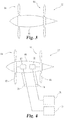
- FIG. 3 one embodiment is depicted of the power plant 52 having a pylon 66 and multiple bladed rotors 64 which in some embodiments are used to produce a motive force for the aircraft 50 (depicted in FIG. 1 ).
- the bladed rotors 64 can be configured to be contra-rotating in some non-limiting embodiments.
- the bladed rotors 64 can take a variety of forms, dimensions, shapes, etc. and can have any number of air moving members 68 distributed circumferentially about the bladed rotor 64.
- the air moving members 68 can have any variety of sweep, camber, twist, and stagger, suitable for use with the power plant 52, to set forth just a few non-exclusive examples.
- the air moving members 68 can be configured to have variable pitch provided by a suitable mechanism such as, but not limited to, a motor driven gearing.
- the air moving members 68 associated with any given bladed rotor 64, such as the upstream bladed rotor 64, can have the same characteristics/configuration as corresponding air moving members 68 associated with another bladed rotor 64, such as the downstream bladed rotor 64, but in some embodiments the characteristics and/or configuration can be different.
- the illustrated embodiment depicts two bladed rotors 64 associated with the pylon 66, in some forms the aircraft 50 and/or power plant 52 can include any number of bladed rotors 64 with the pylon 66 having any variety of configurations and placements as described herein.
- FIG. 3 depicts the bladed rotors 64 on either side of the pylon 66, in some embodiments the rotors 64 can be spaced closer to one another.
- both rotors 64 could be disposed at a downstream side of the pylon 66, while other embodiments could locate the rotors 64 at an upstream side.
- Other placements are also contemplated herein for any of the rotors 64.
- the bladed rotors 64 are capable of being separately powered by work devices 70 and 72.
- the work devices 70 and 72 can be configured to independently drive the bladed rotors 64 at operating conditions that can be different in some modes of operation, or the same/similar in other modes of operation.
- the work devices 70 and 72 can be operated either directly or indirectly to drive the bladed rotors 64 at different speeds.
- the work devices 70 and 72 can also provide varying levels of work to the bladed rotors 64.
- the air moving members 68 in an upstream bladed rotor 64 can be commanded to a different pitch than air moving members 68 associated with a downstream bladed rotor.
- the aircraft 50 can be operated to produce varying speeds and/or configurations based upon a forward speed of the aircraft 50.
- the speed and/or configuration of the bladed rotor 64 can be adjusted to provide for an improved and/or optimized noise signature, such as might be useful in a take-off operation around a noise sensitive environment.
- the speed and/or configuration of the bladed rotor could also be adjusted to improve and/or optimize a performance of the aircraft 50.
- the controller 56 can determine appropriate speed and/or configuration of the bladed rotor 64 and command each work producing device 70 and 72 accordingly.
- the sensor 54 can be used to determine a speed of the aircraft 50, the information of which is provided to the controller 56 to determine an appropriate speed of the each of the bladed rotors 64.
- the controller 56 can command an absolute speed and/or configuration of each bladed rotor 64, while in another form the controller 56 can command a relative speed and/or configuration.
- the controller 56 is capable of generating a delta command to one or both of the bladed rotors based on a baseline command.
- the delta command can take the form of a command expressed as an increment to be summed with a baseline command. Such an increment can be expressed in the same units as the baseline command or as a percentage of it.
- the baseline command can represent a command to be issued corresponding to one of the bladed rotors 64.
- the controller 56 can operate each of the work devices 70 and 72 to provide for appropriate speed and/or configuration of the bladed rotors 64.
- the power transfer devices can include a shaft driven by the work devices 70 and 72, such as by shafts 74 and 76.
- the shafts 74 and 76 are drivingly coupled to the bladed rotors 64 via gearboxes 78 and 80, but other embodiments need not include such a device.
- the gearboxes 78 and 80 can include any number of components useful in changing a direction and/or ratio of rotation of the shafts 74 and 76.
- gearboxes 78 and 80 can be a transmission which in some forms can include a variety of mechanisms to change the ratio of rotation from either of the shafts 74 and 76 to the bladed rotors 64. Such a transmission can provide for a variety of ratios as will be appreciated.
- gearboxes 78 and 80 can include power modulators such as one or more clutches.
- the illustrated embodiment depicts various shafts and gearboxes 78 and 80, some forms of the power plant 52 may not include such devices.
- the work devices 70 and 72 can be coupled directly to the bladed rotor 64, either through a shaft or similar device, and/or can be integrated thereto.
- the work devices 70 and 72 can take a variety of forms in various embodiments.
- one or more of the work devices 70 and 72 can be an internal combustion engine (such as but not limited to gas turbine engines and positive displacement engines) or an electric motor.
- the work devices 70 and 72 can be configured to operate on the basis of a fuel or energy storage and in some forms both work devices 70 and 72 can pull from the same fuel or energy storage.
- the work devices 70 and 72 were configured as internal combustion engines the devices can receive fuel from the same storage container, such as a vehicle fuel tank.
- the work devices 70 and 72 were electric motors, such motors can receive electrical power from a common source, such as a generator or battery.
- the work devices 70 and 72 can receive fuel or energy from separate sources, such as but not limited to separate fuel containers or separate sources of electricity.
- Other forms of work devices and fuel/energy storage can also be used suitable to any given application.
- the work devices 70 and 72 can be the same type in any given embodiment of the power plant 52.
- the devices 70 and 72 can both be gas turbine engines, or positive displacement engines, or electric motors.
- the work devices 70 and 72 can take different forms, such as work device 70 in the form of an internal combustion engine and work device 72 in the form of an electric motor.
- one or more of the work devices 70 and 72 can be an off-the-shelf device integrated into the power plant 52 with minimal to no changes. In other applications one or more of the work devices 70 and 72 can be modified either moderately or substantially before integration with the power plant 52. In still further forms one or more of the work devices 70 and 72 can be substantially reconstructed and/or be devices specifically designed for the application to be used in the power plant 52.
- Another aspect of the present application provides a method comprising operating an aircraft power plant to develop thrust, the operating including: rotating a first bladed air moving device to produce a first flow stream by action of a first power source, delivering the first flow stream to a second bladed air moving device powered by a second power source, independently driving each of the first bladed air moving device and second bladed air moving device from the first power source and second power source respectively.
- the rotating may include spinning the first bladed air moving device as an open rotor.
- the method may include providing power from the first power source to the first bladed air moving device, the first power source located radially offset from a rotation of the first bladed air moving device.
- the providing power includes rotating a shaft in mechanical communication with the first bladed air moving device.
- the method may further include rotating a gearing coupled to the shaft and the first bladed air moving device.
Claims (15)
- Appareil comprenant :un groupe motopropulseur d'avion (52) présentant un premier dispositif de mise en œuvre (70) et un second dispositif de mise en œuvre (72) ;un premier dispositif de déplacement d'air libre (64) en communication fluidique en série avec un second dispositif de déplacement d'air libre (64), le premier dispositif de déplacement d'air libre (64) étant alimenté par le premier dispositif de mise en œuvre (70) et le second dispositif de déplacement d'air libre étant alimenté par le second dispositif de mise en œuvre (72) ; caractérisé en ce qu'il présenteun système de commande (56) configuré afin de commander le premier dispositif de déplacement d'air libre (64), afin de tourner à une vitesse différente relativement au second dispositif de déplacement d'air libre (64), dans lequel le système de commande (56) inclut un module configuré afin de fournir la commande sur la base d'une fonction de vitesse d'air.
- Appareil selon la revendication 1, dans lequel le premier dispositif de mise en œuvre (70) est un parmi un moteur à combustion interne et un moteur électrique, et le second dispositif de mise en œuvre (72) est un parmi un moteur à combustion interne et un moteur électrique, éventuellement dans lequel le premier dispositif de mise en œuvre (70) est du même type que le second dispositif de mise en œuvre (72).
- Appareil selon la revendication 1, dans lequel le premier dispositif de mise en œuvre (70) inclut une turbine (62) structurée afin d'extraire de l'énergie d'un courant d'écoulement passant, éventuellement dans lequel la turbine (62) est en aval d'un système de combustion (60), et dans lequel le premier dispositif de déplacement d'air libre (64) est capable de tourner à une première vitesse de rotation et le second dispositif de déplacement d'air libre (64) est capable de tourner à une seconde vitesse de rotation.
- Appareil selon la revendication 1, dans lequel le système de commande (56) est structuré afin de développer un signal de commande au premier dispositif de mise en œuvre (70).
- Appareil selon la revendication 1, dans lequel :(i) les dispositifs de déplacement d'air libre (64) sont des rotors ouverts ; ou(ii) le premier dispositif de déplacement d'air libre peut être commandé à une vitesse différente du second dispositif de déplacement d'air libre ; ou(iii) l'appareil inclut en outre un système de commande configuré afin de générer un signal représentatif d'une vitesse, utilisée afin d'entraîner le premier dispositif de déplacement d'air libre (64) à une première vitesse.
- Appareil selon la revendication 1, dans lequel le premier dispositif de mise en œuvre (70) est un parmi un moteur à combustion interne et un moteur électrique.
- Appareil selon la revendication 6, dans lequel le premier dispositif de mise en œuvre (70) est décalé de manière radiale d'un axe de rotation du premier dispositif de déplacement d'air libre (64).
- Appareil selon la revendication 6 ou la revendication 7, dans lequel le premier dispositif de mise en œuvre (70) est raccordé via un arbre (74) au premier dispositif de déplacement d'air libre (64).
- Procédé comprenant :
l'actionnement d'un groupe motopropulseur d'avion (52) permettant de développer une poussée, l'actionnement incluant :la rotation d'un premier dispositif de déplacement d'air à pale (64) permettant de produire un premier courant d'écoulement par l'action d'une première source d'alimentation (70) ;la fourniture du premier courant d'écoulement à un second dispositif de déplacement d'air à pale (64) alimenté par une seconde source d'alimentation (72) ;caractérisé en ce qu'il comprendl'entraînement indépendamment de chacun du premier dispositif de déplacement d'air à pale (64) et du second dispositif de déplacement d'air à pale (64) de la première source d'alimentation (70) et de la seconde source d'alimentation (72), respectivement, dans lequel le premier dispositif de déplacement d'air à pale (64) est entraîné afin de tourner à une vitesse différente relativement au second dispositif de déplacement d'air à pale (64) sur la base d'une fonction de vitesse de l'air. - Procédé selon la revendication 9, dans lequel la rotation inclut la rotation du dispositif de déplacement d'air à pale (64) comme un rotor ouvert.
- Procédé selon la revendication 9, dans lequel le premier dispositif de déplacement d'air à pale (64) est capable de tourner à une vitesse différente du second dispositif de déplacement d'air à pale (64).
- Procédé selon la revendication 9, qui inclut en outre la fourniture d'une alimentation provenant de la première source d'alimentation (70) au premier dispositif de déplacement d'air à pale (64), la première source d'alimentation (70) étant située de manière radialement décalée d'un axe de rotation du premier dispositif de déplacement d'air à pale (64).
- Procédé selon la revendication 12, dans lequel la fourniture d'alimentation inclut la rotation d'un arbre (74) en communication mécanique avec le premier dispositif de déplacement d'air à pale (64).
- Procédé selon la revendication 13, qui inclut en outre la rotation d'un engrenage (78) raccordé à l'arbre (74) et au premier dispositif de déplacement d'air à pale (64).
- Procédé selon la revendication 13, dans lequel la première source d'alimentation (70) est un parmi un moteur à combustion interne et un dispositif électrique.
Applications Claiming Priority (2)
| Application Number | Priority Date | Filing Date | Title |
|---|---|---|---|
| US201361775554P | 2013-03-09 | 2013-03-09 | |
| PCT/US2013/076521 WO2014163688A1 (fr) | 2013-03-09 | 2013-12-19 | Groupe motopropulseur d'avion |
Publications (2)
| Publication Number | Publication Date |
|---|---|
| EP2964530A1 EP2964530A1 (fr) | 2016-01-13 |
| EP2964530B1 true EP2964530B1 (fr) | 2019-10-30 |
Family
ID=49956419
Family Applications (1)
| Application Number | Title | Priority Date | Filing Date |
|---|---|---|---|
| EP13821303.8A Active EP2964530B1 (fr) | 2013-03-09 | 2013-12-19 | Groupe motopropulseur d'avion |
Country Status (3)
| Country | Link |
|---|---|
| US (1) | US9581025B2 (fr) |
| EP (1) | EP2964530B1 (fr) |
| WO (1) | WO2014163688A1 (fr) |
Families Citing this family (31)
| Publication number | Priority date | Publication date | Assignee | Title |
|---|---|---|---|---|
| US10000293B2 (en) | 2015-01-23 | 2018-06-19 | General Electric Company | Gas-electric propulsion system for an aircraft |
| CN104590568A (zh) * | 2015-02-02 | 2015-05-06 | 上海交通大学 | 长航时混合动力无人机 |
| US9815560B2 (en) | 2015-09-21 | 2017-11-14 | General Electric Company | AFT engine nacelle shape for an aircraft |
| US9957055B2 (en) | 2015-09-21 | 2018-05-01 | General Electric Company | Aft engine for an aircraft |
| US9884687B2 (en) | 2015-09-21 | 2018-02-06 | General Electric Company | Non-axis symmetric aft engine |
| US9821917B2 (en) | 2015-09-21 | 2017-11-21 | General Electric Company | Aft engine for an aircraft |
| US9637217B2 (en) | 2015-09-21 | 2017-05-02 | General Electric Company | Aircraft having an aft engine |
| US10017270B2 (en) | 2015-10-09 | 2018-07-10 | General Electric Company | Aft engine for an aircraft |
| WO2017137227A1 (fr) * | 2016-02-12 | 2017-08-17 | Siemens Aktiengesellschaft | Ligne de turbine à gaz munie d'un moteur de démarrage |
| US9764848B1 (en) | 2016-03-07 | 2017-09-19 | General Electric Company | Propulsion system for an aircraft |
| US10392119B2 (en) | 2016-04-11 | 2019-08-27 | General Electric Company | Electric propulsion engine for an aircraft |
| US10392120B2 (en) | 2016-04-19 | 2019-08-27 | General Electric Company | Propulsion engine for an aircraft |
| US10252810B2 (en) | 2016-04-19 | 2019-04-09 | General Electric Company | Propulsion engine for an aircraft |
| US10800539B2 (en) * | 2016-08-19 | 2020-10-13 | General Electric Company | Propulsion engine for an aircraft |
| US11105340B2 (en) | 2016-08-19 | 2021-08-31 | General Electric Company | Thermal management system for an electric propulsion engine |
| US10676205B2 (en) | 2016-08-19 | 2020-06-09 | General Electric Company | Propulsion engine for an aircraft |
| US10308366B2 (en) | 2016-08-22 | 2019-06-04 | General Electric Company | Embedded electric machine |
| US10487839B2 (en) | 2016-08-22 | 2019-11-26 | General Electric Company | Embedded electric machine |
| US10093428B2 (en) | 2016-08-22 | 2018-10-09 | General Electric Company | Electric propulsion system |
| US10071811B2 (en) | 2016-08-22 | 2018-09-11 | General Electric Company | Embedded electric machine |
| US10526069B1 (en) * | 2016-09-08 | 2020-01-07 | Northrop Grumman Systems Corporation | Collapsible large diameter propeller for quiet aircraft |
| US11149578B2 (en) | 2017-02-10 | 2021-10-19 | General Electric Company | Propulsion system for an aircraft |
| US10822103B2 (en) | 2017-02-10 | 2020-11-03 | General Electric Company | Propulsor assembly for an aircraft |
| US10793281B2 (en) | 2017-02-10 | 2020-10-06 | General Electric Company | Propulsion system for an aircraft |
| US10137981B2 (en) | 2017-03-31 | 2018-11-27 | General Electric Company | Electric propulsion system for an aircraft |
| FR3067056B1 (fr) * | 2017-06-01 | 2019-07-26 | Safran Aircraft Engines | Turboreacteur du type a rotor non carene |
| US10762726B2 (en) | 2017-06-13 | 2020-09-01 | General Electric Company | Hybrid-electric propulsion system for an aircraft |
| US11156128B2 (en) | 2018-08-22 | 2021-10-26 | General Electric Company | Embedded electric machine |
| US11097849B2 (en) | 2018-09-10 | 2021-08-24 | General Electric Company | Aircraft having an aft engine |
| US11597514B2 (en) * | 2019-08-16 | 2023-03-07 | Embraer S.A. | Unmanned aircraft having reduced acoustic signatures |
| US11725590B2 (en) | 2020-10-22 | 2023-08-15 | General Electric Company | Turbomachine and gear assembly |
Citations (1)
| Publication number | Priority date | Publication date | Assignee | Title |
|---|---|---|---|---|
| WO2014108125A1 (fr) * | 2013-01-10 | 2014-07-17 | Malte Schwarze | Aéronef à rendement élevé et à faible bruit |
Family Cites Families (34)
| Publication number | Priority date | Publication date | Assignee | Title |
|---|---|---|---|---|
| DE315109C (fr) * | ||||
| FR503396A (fr) * | 1917-05-22 | 1920-06-09 | Aviation Louis Breguet Sa | Groupe propulseur pour appareils aériens |
| US1394870A (en) * | 1920-02-28 | 1921-10-25 | Thomas Morse Aircraft Corp | Driving connections for airplane-engines |
| FR543471A (fr) * | 1920-12-04 | 1922-09-04 | Soc It Ernesto Breda | Perfectionnements apportés aux groupes moto-propulseurs pour machines aériennes, et plus spécialement pour aéroplanes et hydroplanes |
| US2159758A (en) * | 1936-09-24 | 1939-05-23 | Gen Electric | Power plant |
| DE728044C (de) * | 1937-08-03 | 1942-11-18 | Dornier Werke Gmbh | Flugzeug mit zwei hintereinander angeordneten Motoren |
| US2380889A (en) * | 1941-07-26 | 1945-07-31 | Waseige Charles Raymond | Polyengine bipropeller drive |
| US2406625A (en) * | 1941-12-10 | 1946-08-27 | Thomas W Oglesby | Airplane |
| US2470155A (en) * | 1942-05-16 | 1949-05-17 | Fairey Aviat Co Ltd | Power plant assembly |
| US2581320A (en) * | 1945-07-20 | 1952-01-01 | Douglas Aircraft Co Inc | Multiengine contra-rotating propeller drive transmission |
| US2518841A (en) * | 1945-12-15 | 1950-08-15 | Packard Motor Car Co | Propeller drive for airplanes with counter-rotating propellers |
| FR943553A (fr) * | 1946-03-12 | 1949-03-11 | Bristol Aeroplane Co Ltd | Perfectionnements aux groupes moto-propulseurs pour avions |
| US2753005A (en) * | 1951-12-29 | 1956-07-03 | Adolphe C Peterson | Tiltable rotor unit with counterrotating propellers |
| US3335979A (en) * | 1965-10-22 | 1967-08-15 | B E Wallace Developments Inc | Aircraft |
| US3470961A (en) * | 1967-09-19 | 1969-10-07 | Joseph L Halsmer | Dual engine starting clutch |
| DE1802518B1 (de) * | 1968-10-11 | 1970-04-09 | Bodenseewerk Geraetetech | Geschwindigkeitsregler fuer Flugzeuge |
| US4426049A (en) * | 1981-07-31 | 1984-01-17 | Stewart Donald M | Dual propeller and engine drive system for aircraft |
| US5079916A (en) | 1982-11-01 | 1992-01-14 | General Electric Company | Counter rotation power turbine |
| DE3347679C2 (de) * | 1983-12-31 | 1985-11-14 | Sita Bauelemente Gmbh, 2080 Pinneberg | Doppelpropeller |
| DE3629867A1 (de) * | 1986-09-02 | 1988-03-10 | Sita Bauelemente | Zahnradgetriebe fuer luftfahrzeuge |
| US4976102A (en) | 1988-05-09 | 1990-12-11 | General Electric Company | Unducted, counterrotating gearless front fan engine |
| US5221185A (en) | 1991-08-05 | 1993-06-22 | General Electric Company | Method and apparatus for synchronizing rotating machinery to reduce noise |
| FR2762585B1 (fr) * | 1997-04-24 | 1999-06-04 | Snecma | Systeme de motorisation d'un avion de transport a helices |
| GB0702608D0 (en) | 2007-02-10 | 2007-03-21 | Rolls Royce Plc | Aeroengine |
| CZ300681B6 (cs) * | 2008-08-20 | 2009-07-15 | Vycítal@Jirí | Hybridní pohon letadla |
| DE102008062813A1 (de) * | 2008-12-23 | 2010-07-15 | Rolls-Royce Deutschland Ltd & Co Kg | Flugzeug mit einer Heck-Propeller-Triebwerksanordnung |
| US8182222B2 (en) | 2009-02-12 | 2012-05-22 | Hamilton Sundstrand Corporation | Thermal protection of rotor blades |
| US8661781B2 (en) | 2009-02-13 | 2014-03-04 | The Boeing Company | Counter rotating fan design and variable blade row spacing optimization for low environmental impact |
| US8294316B2 (en) | 2009-07-28 | 2012-10-23 | Rolls-Royce North American Technologies, Inc. | Electrical power generation apparatus for contra-rotating open-rotor aircraft propulsion system |
| FR2949434B1 (fr) * | 2009-08-28 | 2011-10-07 | Benjamin Parzy | Aeronef comportant au moins deux groupes motopropulseurs electriques montes a l'arriere |
| US8689538B2 (en) | 2009-09-09 | 2014-04-08 | The Boeing Company | Ultra-efficient propulsor with an augmentor fan circumscribing a turbofan |
| GB2473651B (en) | 2009-09-21 | 2011-08-31 | Rolls Royce Plc | Gas turbine aircraft engines and operation thereof |
| GB2474286B (en) | 2009-10-12 | 2011-08-31 | Rolls Royce Plc | A propulsion engine |
| US8701381B2 (en) * | 2010-11-24 | 2014-04-22 | Rolls-Royce Corporation | Remote shaft driven open rotor propulsion system with electrical power generation |
-
2013
- 2013-12-19 EP EP13821303.8A patent/EP2964530B1/fr active Active
- 2013-12-19 WO PCT/US2013/076521 patent/WO2014163688A1/fr active Application Filing
- 2013-12-27 US US14/142,166 patent/US9581025B2/en active Active
Patent Citations (1)
| Publication number | Priority date | Publication date | Assignee | Title |
|---|---|---|---|---|
| WO2014108125A1 (fr) * | 2013-01-10 | 2014-07-17 | Malte Schwarze | Aéronef à rendement élevé et à faible bruit |
Also Published As
| Publication number | Publication date |
|---|---|
| US20140250861A1 (en) | 2014-09-11 |
| WO2014163688A1 (fr) | 2014-10-09 |
| EP2964530A1 (fr) | 2016-01-13 |
| US9581025B2 (en) | 2017-02-28 |
Similar Documents
| Publication | Publication Date | Title |
|---|---|---|
| EP2964530B1 (fr) | Groupe motopropulseur d'avion | |
| EP3403933B1 (fr) | Système de propulsion hybride-électrique pour un aéronef | |
| EP3428068B1 (fr) | Système de propulsion pour aéronef | |
| EP3421369B1 (fr) | Système de propulsion pour aéronef | |
| CA3009027C (fr) | Systeme de propulsion destine a un aeronef | |
| EP3421368B1 (fr) | Système de propulsion pour aéronef | |
| US8935912B2 (en) | Gas turbine engine with variable overall pressure ratio | |
| CA3008982C (fr) | Systeme de propulsion destine a un aeronef | |
| US8562284B2 (en) | Propulsive fan system | |
| EP3421371B1 (fr) | Système de propulsion pour aéronef | |
| US9482156B2 (en) | Vehicle recuperator | |
| CN114104303A (zh) | 飞行器的推进系统 | |
| WO2023225439A2 (fr) | Turboréacteur hybride à train planétaire pour mélange d'énergie entre une sortie électrique et un ventilateur de dérivation à poussée variable |
Legal Events
| Date | Code | Title | Description |
|---|---|---|---|
| PUAI | Public reference made under article 153(3) epc to a published international application that has entered the european phase |
Free format text: ORIGINAL CODE: 0009012 |
|
| 17P | Request for examination filed |
Effective date: 20150828 |
|
| AK | Designated contracting states |
Kind code of ref document: A1 Designated state(s): AL AT BE BG CH CY CZ DE DK EE ES FI FR GB GR HR HU IE IS IT LI LT LU LV MC MK MT NL NO PL PT RO RS SE SI SK SM TR |
|
| AX | Request for extension of the european patent |
Extension state: BA ME |
|
| DAX | Request for extension of the european patent (deleted) | ||
| STAA | Information on the status of an ep patent application or granted ep patent |
Free format text: STATUS: EXAMINATION IS IN PROGRESS |
|
| 17Q | First examination report despatched |
Effective date: 20170601 |
|
| RIC1 | Information provided on ipc code assigned before grant |
Ipc: F01B 23/00 20060101ALI20190410BHEP Ipc: F02C 7/36 20060101ALI20190410BHEP Ipc: F02C 9/44 20060101ALI20190410BHEP Ipc: B64D 27/00 20060101ALI20190410BHEP Ipc: F02C 9/42 20060101ALI20190410BHEP Ipc: B64D 27/02 20060101AFI20190410BHEP Ipc: B64D 33/02 20060101ALI20190410BHEP |
|
| GRAP | Despatch of communication of intention to grant a patent |
Free format text: ORIGINAL CODE: EPIDOSNIGR1 |
|
| STAA | Information on the status of an ep patent application or granted ep patent |
Free format text: STATUS: GRANT OF PATENT IS INTENDED |
|
| INTG | Intention to grant announced |
Effective date: 20190517 |
|
| GRAS | Grant fee paid |
Free format text: ORIGINAL CODE: EPIDOSNIGR3 |
|
| GRAA | (expected) grant |
Free format text: ORIGINAL CODE: 0009210 |
|
| STAA | Information on the status of an ep patent application or granted ep patent |
Free format text: STATUS: THE PATENT HAS BEEN GRANTED |
|
| AK | Designated contracting states |
Kind code of ref document: B1 Designated state(s): AL AT BE BG CH CY CZ DE DK EE ES FI FR GB GR HR HU IE IS IT LI LT LU LV MC MK MT NL NO PL PT RO RS SE SI SK SM TR |
|
| REG | Reference to a national code |
Ref country code: GB Ref legal event code: FG4D |
|
| REG | Reference to a national code |
Ref country code: CH Ref legal event code: EP |
|
| REG | Reference to a national code |
Ref country code: AT Ref legal event code: REF Ref document number: 1195883 Country of ref document: AT Kind code of ref document: T Effective date: 20191115 |
|
| REG | Reference to a national code |
Ref country code: DE Ref legal event code: R096 Ref document number: 602013062311 Country of ref document: DE |
|
| REG | Reference to a national code |
Ref country code: IE Ref legal event code: FG4D |
|
| REG | Reference to a national code |
Ref country code: LT Ref legal event code: MG4D |
|
| PG25 | Lapsed in a contracting state [announced via postgrant information from national office to epo] |
Ref country code: PT Free format text: LAPSE BECAUSE OF FAILURE TO SUBMIT A TRANSLATION OF THE DESCRIPTION OR TO PAY THE FEE WITHIN THE PRESCRIBED TIME-LIMIT Effective date: 20200302 Ref country code: LV Free format text: LAPSE BECAUSE OF FAILURE TO SUBMIT A TRANSLATION OF THE DESCRIPTION OR TO PAY THE FEE WITHIN THE PRESCRIBED TIME-LIMIT Effective date: 20191030 Ref country code: FI Free format text: LAPSE BECAUSE OF FAILURE TO SUBMIT A TRANSLATION OF THE DESCRIPTION OR TO PAY THE FEE WITHIN THE PRESCRIBED TIME-LIMIT Effective date: 20191030 Ref country code: BG Free format text: LAPSE BECAUSE OF FAILURE TO SUBMIT A TRANSLATION OF THE DESCRIPTION OR TO PAY THE FEE WITHIN THE PRESCRIBED TIME-LIMIT Effective date: 20200130 Ref country code: SE Free format text: LAPSE BECAUSE OF FAILURE TO SUBMIT A TRANSLATION OF THE DESCRIPTION OR TO PAY THE FEE WITHIN THE PRESCRIBED TIME-LIMIT Effective date: 20191030 Ref country code: LT Free format text: LAPSE BECAUSE OF FAILURE TO SUBMIT A TRANSLATION OF THE DESCRIPTION OR TO PAY THE FEE WITHIN THE PRESCRIBED TIME-LIMIT Effective date: 20191030 Ref country code: NO Free format text: LAPSE BECAUSE OF FAILURE TO SUBMIT A TRANSLATION OF THE DESCRIPTION OR TO PAY THE FEE WITHIN THE PRESCRIBED TIME-LIMIT Effective date: 20200130 Ref country code: GR Free format text: LAPSE BECAUSE OF FAILURE TO SUBMIT A TRANSLATION OF THE DESCRIPTION OR TO PAY THE FEE WITHIN THE PRESCRIBED TIME-LIMIT Effective date: 20200131 Ref country code: PL Free format text: LAPSE BECAUSE OF FAILURE TO SUBMIT A TRANSLATION OF THE DESCRIPTION OR TO PAY THE FEE WITHIN THE PRESCRIBED TIME-LIMIT Effective date: 20191030 Ref country code: ES Free format text: LAPSE BECAUSE OF FAILURE TO SUBMIT A TRANSLATION OF THE DESCRIPTION OR TO PAY THE FEE WITHIN THE PRESCRIBED TIME-LIMIT Effective date: 20191030 Ref country code: NL Free format text: LAPSE BECAUSE OF FAILURE TO SUBMIT A TRANSLATION OF THE DESCRIPTION OR TO PAY THE FEE WITHIN THE PRESCRIBED TIME-LIMIT Effective date: 20191030 |
|
| REG | Reference to a national code |
Ref country code: NL Ref legal event code: MP Effective date: 20191030 |
|
| PG25 | Lapsed in a contracting state [announced via postgrant information from national office to epo] |
Ref country code: HR Free format text: LAPSE BECAUSE OF FAILURE TO SUBMIT A TRANSLATION OF THE DESCRIPTION OR TO PAY THE FEE WITHIN THE PRESCRIBED TIME-LIMIT Effective date: 20191030 Ref country code: IS Free format text: LAPSE BECAUSE OF FAILURE TO SUBMIT A TRANSLATION OF THE DESCRIPTION OR TO PAY THE FEE WITHIN THE PRESCRIBED TIME-LIMIT Effective date: 20200229 Ref country code: RS Free format text: LAPSE BECAUSE OF FAILURE TO SUBMIT A TRANSLATION OF THE DESCRIPTION OR TO PAY THE FEE WITHIN THE PRESCRIBED TIME-LIMIT Effective date: 20191030 |
|
| PG25 | Lapsed in a contracting state [announced via postgrant information from national office to epo] |
Ref country code: AL Free format text: LAPSE BECAUSE OF FAILURE TO SUBMIT A TRANSLATION OF THE DESCRIPTION OR TO PAY THE FEE WITHIN THE PRESCRIBED TIME-LIMIT Effective date: 20191030 |
|
| PG25 | Lapsed in a contracting state [announced via postgrant information from national office to epo] |
Ref country code: EE Free format text: LAPSE BECAUSE OF FAILURE TO SUBMIT A TRANSLATION OF THE DESCRIPTION OR TO PAY THE FEE WITHIN THE PRESCRIBED TIME-LIMIT Effective date: 20191030 Ref country code: DK Free format text: LAPSE BECAUSE OF FAILURE TO SUBMIT A TRANSLATION OF THE DESCRIPTION OR TO PAY THE FEE WITHIN THE PRESCRIBED TIME-LIMIT Effective date: 20191030 Ref country code: CZ Free format text: LAPSE BECAUSE OF FAILURE TO SUBMIT A TRANSLATION OF THE DESCRIPTION OR TO PAY THE FEE WITHIN THE PRESCRIBED TIME-LIMIT Effective date: 20191030 Ref country code: RO Free format text: LAPSE BECAUSE OF FAILURE TO SUBMIT A TRANSLATION OF THE DESCRIPTION OR TO PAY THE FEE WITHIN THE PRESCRIBED TIME-LIMIT Effective date: 20191030 |
|
| REG | Reference to a national code |
Ref country code: CH Ref legal event code: PL Ref country code: DE Ref legal event code: R097 Ref document number: 602013062311 Country of ref document: DE |
|
| REG | Reference to a national code |
Ref country code: AT Ref legal event code: MK05 Ref document number: 1195883 Country of ref document: AT Kind code of ref document: T Effective date: 20191030 |
|
| REG | Reference to a national code |
Ref country code: BE Ref legal event code: MM Effective date: 20191231 |
|
| PG25 | Lapsed in a contracting state [announced via postgrant information from national office to epo] |
Ref country code: SM Free format text: LAPSE BECAUSE OF FAILURE TO SUBMIT A TRANSLATION OF THE DESCRIPTION OR TO PAY THE FEE WITHIN THE PRESCRIBED TIME-LIMIT Effective date: 20191030 Ref country code: IT Free format text: LAPSE BECAUSE OF FAILURE TO SUBMIT A TRANSLATION OF THE DESCRIPTION OR TO PAY THE FEE WITHIN THE PRESCRIBED TIME-LIMIT Effective date: 20191030 Ref country code: SK Free format text: LAPSE BECAUSE OF FAILURE TO SUBMIT A TRANSLATION OF THE DESCRIPTION OR TO PAY THE FEE WITHIN THE PRESCRIBED TIME-LIMIT Effective date: 20191030 Ref country code: MC Free format text: LAPSE BECAUSE OF FAILURE TO SUBMIT A TRANSLATION OF THE DESCRIPTION OR TO PAY THE FEE WITHIN THE PRESCRIBED TIME-LIMIT Effective date: 20191030 |
|
| PLBE | No opposition filed within time limit |
Free format text: ORIGINAL CODE: 0009261 |
|
| STAA | Information on the status of an ep patent application or granted ep patent |
Free format text: STATUS: NO OPPOSITION FILED WITHIN TIME LIMIT |
|
| GBPC | Gb: european patent ceased through non-payment of renewal fee |
Effective date: 20200130 |
|
| 26N | No opposition filed |
Effective date: 20200731 |
|
| PG25 | Lapsed in a contracting state [announced via postgrant information from national office to epo] |
Ref country code: GB Free format text: LAPSE BECAUSE OF NON-PAYMENT OF DUE FEES Effective date: 20200130 Ref country code: LU Free format text: LAPSE BECAUSE OF NON-PAYMENT OF DUE FEES Effective date: 20191219 Ref country code: IE Free format text: LAPSE BECAUSE OF NON-PAYMENT OF DUE FEES Effective date: 20191219 |
|
| PG25 | Lapsed in a contracting state [announced via postgrant information from national office to epo] |
Ref country code: BE Free format text: LAPSE BECAUSE OF NON-PAYMENT OF DUE FEES Effective date: 20191231 Ref country code: LI Free format text: LAPSE BECAUSE OF NON-PAYMENT OF DUE FEES Effective date: 20191231 Ref country code: AT Free format text: LAPSE BECAUSE OF FAILURE TO SUBMIT A TRANSLATION OF THE DESCRIPTION OR TO PAY THE FEE WITHIN THE PRESCRIBED TIME-LIMIT Effective date: 20191030 Ref country code: CH Free format text: LAPSE BECAUSE OF NON-PAYMENT OF DUE FEES Effective date: 20191231 Ref country code: SI Free format text: LAPSE BECAUSE OF FAILURE TO SUBMIT A TRANSLATION OF THE DESCRIPTION OR TO PAY THE FEE WITHIN THE PRESCRIBED TIME-LIMIT Effective date: 20191030 |
|
| PG25 | Lapsed in a contracting state [announced via postgrant information from national office to epo] |
Ref country code: CY Free format text: LAPSE BECAUSE OF FAILURE TO SUBMIT A TRANSLATION OF THE DESCRIPTION OR TO PAY THE FEE WITHIN THE PRESCRIBED TIME-LIMIT Effective date: 20191030 |
|
| PG25 | Lapsed in a contracting state [announced via postgrant information from national office to epo] |
Ref country code: MT Free format text: LAPSE BECAUSE OF FAILURE TO SUBMIT A TRANSLATION OF THE DESCRIPTION OR TO PAY THE FEE WITHIN THE PRESCRIBED TIME-LIMIT Effective date: 20191030 Ref country code: HU Free format text: LAPSE BECAUSE OF FAILURE TO SUBMIT A TRANSLATION OF THE DESCRIPTION OR TO PAY THE FEE WITHIN THE PRESCRIBED TIME-LIMIT; INVALID AB INITIO Effective date: 20131219 |
|
| PG25 | Lapsed in a contracting state [announced via postgrant information from national office to epo] |
Ref country code: TR Free format text: LAPSE BECAUSE OF FAILURE TO SUBMIT A TRANSLATION OF THE DESCRIPTION OR TO PAY THE FEE WITHIN THE PRESCRIBED TIME-LIMIT Effective date: 20191030 |
|
| PG25 | Lapsed in a contracting state [announced via postgrant information from national office to epo] |
Ref country code: MK Free format text: LAPSE BECAUSE OF FAILURE TO SUBMIT A TRANSLATION OF THE DESCRIPTION OR TO PAY THE FEE WITHIN THE PRESCRIBED TIME-LIMIT Effective date: 20191030 |
|
| PGFP | Annual fee paid to national office [announced via postgrant information from national office to epo] |
Ref country code: DE Payment date: 20221227 Year of fee payment: 10 |
|
| P01 | Opt-out of the competence of the unified patent court (upc) registered |
Effective date: 20230528 |
|
| PGFP | Annual fee paid to national office [announced via postgrant information from national office to epo] |
Ref country code: FR Payment date: 20231226 Year of fee payment: 11 |