EP2964488B1 - Recess steps for cab access - Google Patents
Recess steps for cab access Download PDFInfo
- Publication number
- EP2964488B1 EP2964488B1 EP14710768.4A EP14710768A EP2964488B1 EP 2964488 B1 EP2964488 B1 EP 2964488B1 EP 14710768 A EP14710768 A EP 14710768A EP 2964488 B1 EP2964488 B1 EP 2964488B1
- Authority
- EP
- European Patent Office
- Prior art keywords
- cab
- chassis
- door
- fairing
- fender
- Prior art date
- Legal status (The legal status is an assumption and is not a legal conclusion. Google has not performed a legal analysis and makes no representation as to the accuracy of the status listed.)
- Active
Links
- 238000000034 method Methods 0.000 claims description 15
- 230000007704 transition Effects 0.000 claims description 8
- 239000003570 air Substances 0.000 description 23
- 239000000725 suspension Substances 0.000 description 8
- 244000261422 Lysimachia clethroides Species 0.000 description 5
- 230000007246 mechanism Effects 0.000 description 5
- 230000005540 biological transmission Effects 0.000 description 3
- 230000008901 benefit Effects 0.000 description 2
- 230000000694 effects Effects 0.000 description 2
- 239000002828 fuel tank Substances 0.000 description 2
- 239000002184 metal Substances 0.000 description 2
- 239000007921 spray Substances 0.000 description 2
- 241000238631 Hexapoda Species 0.000 description 1
- 239000012080 ambient air Substances 0.000 description 1
- 230000015572 biosynthetic process Effects 0.000 description 1
- 230000008030 elimination Effects 0.000 description 1
- 238000003379 elimination reaction Methods 0.000 description 1
- 239000000463 material Substances 0.000 description 1
- 230000000284 resting effect Effects 0.000 description 1
- 238000000926 separation method Methods 0.000 description 1
Images


Classifications
-
- B—PERFORMING OPERATIONS; TRANSPORTING
- B62—LAND VEHICLES FOR TRAVELLING OTHERWISE THAN ON RAILS
- B62D—MOTOR VEHICLES; TRAILERS
- B62D35/00—Vehicle bodies characterised by streamlining
- B62D35/001—For commercial vehicles or tractor-trailer combinations, e.g. caravans
-
- B—PERFORMING OPERATIONS; TRANSPORTING
- B60—VEHICLES IN GENERAL
- B60R—VEHICLES, VEHICLE FITTINGS, OR VEHICLE PARTS, NOT OTHERWISE PROVIDED FOR
- B60R3/00—Arrangements of steps or ladders facilitating access to or on the vehicle, e.g. running-boards
-
- B—PERFORMING OPERATIONS; TRANSPORTING
- B62—LAND VEHICLES FOR TRAVELLING OTHERWISE THAN ON RAILS
- B62D—MOTOR VEHICLES; TRAILERS
- B62D33/00—Superstructures for load-carrying vehicles
- B62D33/06—Drivers' cabs
- B62D33/0604—Cabs insulated against vibrations or noise, e.g. with elastic suspension
Definitions
- Aerodynamics is a prime consideration in the design of vehicles. There are several factors that contribute to the aerodynamic drag caused by friction of air flowing around the sides of a truck or vehicle. A key to minimizing drag is the reduction or elimination of turbulence.
- An automatically pivotable lid mounted on the chassis is used to cover the steps leading to the door.
- the system further includes a sensor to determine if the door is open or closed. Upon this determination the position of the lid is based to either allow access to the steps or cover them.
- the interface between the cab and chassis also contributes to the aerodynamic drag of the vehicle.
- this interface is typically a horizontal gap created between the bottom edge of the cab and the top of the chassis. Air is drawn into the horizontal gap, which then exits the rear of the cab and into the gap between the cab and semi-trailer. The air hitting the front of the semi-trailer causes increased aerodynamic drag.
- Such a conventional semi-tractor is disclosed in US 2008/0231079 .
- the semi-tractor has a chassis and a cab with a gap between the chassis and the cab to allow free movement of the cab with respect to the chassis.
- a spring is mounted in the gap to urge the cab away from the chassis
- a vehicle includes a cab having a door opening on a side thereof, a chassis that supports the cab, two or more steps leading to the door opening, each of which is supported by the cab or the chassis, wherein the two or more steps are placed within one or more recesses in the cab or chassis, and a door connected to the cab, wherein the door fits within the door opening, and the door comprises a lower door extension having a lower edge that terminates near to an upper surface of a lowermost step, the lower door extension covers a majority of the one or more recesses, and the lower door extension extends outboard to match the outboard extension of a fender or exterior cab side panel to provide a coplanar transition from the fender to the door, or from the door to the exterior cab side panel, or both.
- the vehicle includes a gap created between a lowermost edge of an exterior cab side panel on the cab and a fairing on the chassis, wherein the gap extends along the side of the cab and chassis fairing at least from the rear of the lower door extension to an end of the cab, and the gap is angled greater than 0 degrees with respect to a horizontal direction.
- a width of the gap is sized to approximately match the distance that the cab may travel with respect to the chassis.
- the chassis includes a fender that extends outboard, the lower door extension extends outboard to match the outboard extension of the fender, and the leading edge of the lower door extension is curved inboard where the fender recedes behind the lower door extension.
- the outboard extensions of the fender, the lower door extension, and the chassis fairing are coplanar.
- the cab may further include a side panel separable from and placed to the rear of the lower door extension, and is juxtaposed next to the door and extends outboard to be coplanar with the lower door extension.
- the cab includes an exterior cab side panel that extends below the top of the chassis fairing, and the chassis fairing curves inboard where the chassis fairing recedes behind the exterior cab side panel.
- the cab includes a recess comprising an upper step
- the chassis includes a recess comprising a lower step.
- the recess for the upper step is formed from an exterior cab side panel, and the recess for the lower step is formed from a fairing supported on the chassis.
- the chassis fairing includes a front fender portion, a recess portion for a step, and a main fairing for the chassis.
- the cab can move independently from the chassis.
- Some vehicles are semi-tractors.
- Some vehicles include a cab having an exterior side panel, a chassis that supports the cab, wherein the cab can move independently of the chassis, and wherein the chassis has a fairing, and the exterior side panel has a lower edge that extends below the fairing, and creates a gap that allows the cab to move independent of the chassis without hitting the chassis fairing.
- the gap has an angle greater than 0 with respect to a horizontal direction.
- the exterior cab side panel extends outboard, the chassis extends outboard, and the outboard extension of the exterior cab side panel is coplanar with the outboard extension of the chassis fairing.
- the chassis fairing is curved inboard where the chassis fairing recedes behind the exterior cab side panel.
- Claim 12 defines a method for reducing the aerodynamic drag of a vehicle.
- chassis fairings have been added to cover the fuel tanks and other chassis components.
- Cab access steps are required to enter the driver's cab.
- the cab access steps are typically placed in recesses in the chassis fairings and/or the steps are of reduced depth or they extend out from the fairing surface into the air stream. All of these configurations contribute to turbulent airflow rather than reduce it. In addition, some of these step designs can be difficult to use due to poor visibility and reduced size of the steps.
- the interface between the chassis fairings and the bottom of the cab is another area that contributes to the aerodynamic drag. This interface is typically a horizontal gap to allow for cab movement relative to the chassis. The gap is horizontal and therefore is in line with the airflow allowing air to be drawn underneath the cab or between the cab and chassis, and flow into the low pressure area between the cab back wall and the front of the trailer. This air impacts the front of the trailer, causing additional drag.
- turbulence can be caused by the cab access steps, the transition from the front fender as it joins with the chassis fairing, and the interface between the cab and the chassis fairing. Aspects of the disclosed vehicles can address some of these issues.
- a vehicle is provided with a gradual and smooth transition from the front fender to the cab door and chassis fairing.
- a vehicle has steps that are covered with a lower door extension that requires no additional mechanisms or actuators to expose the steps when the door is opened. This configuration reduces the complexity and allows large, easy to see and use steps.
- the lower door extension also shields the steps from road spray and provides increased security by making it difficult for carjackers to climb onto the cab.
- aerodynamic performance is improved by providing curves and/or bends in the gap between the cab skirt and the chassis fairing.
- the angled configuration restricts the air from flowing into the gap and, therefore, directs more air around the vehicle to avoid the air hitting the front of the trailer.
- FIGURE 1 a semi-tractor 100 having a lower door extension 124 to cover cab access steps leading to the inside of the cab102 and a curved gap 118 between the cab 102 and chassis 106 is illustrated.
- a semi-tractor is used as a representative vehicle to illustrate the various embodiments and is not meant to be limiting of the vehicles.
- Semi-tractors can be distinguished from other vehicles by any one or more of the following features. It is to be appreciated that other vehicles, not normally considered semi-tractors, may also include one or more of these features as well.
- Semi-tractors may include three or more wheel axles, wherein one front axle is the steering axle, and one or both rear axles are drive axles.
- Semi-tractors may include a driver's cab enclosure that is supported on a suspension mechanism, in addition to the wheel suspension on the chassis. Therefore, the cab may move independently of the chassis.
- Semi-tractors may have the engine mounted generally in front of or underneath the cab.
- Semi-tractors may include cabs that are positioned above the engine and/or transmission.
- Semi-tractors may be capable of being repositioned from a riding position to an elevated position to allow access to the engine and/or transmission.
- Semi-tractors generally do not include a cargo box or cargo bed on the chassis, and instead include a hitch positioned forward of the rearmost wheel axel. This allows the semi-tractors to interchange trailers, or to be quickly decoupled from a trailer once the semi-tractor-trailer arrives at the unloading destination. Thus, allowing for more efficient handling of cargo transportation, as the semi-tractor need not wait for the trailer to be unloaded.
- the vehicle 100 includes a cab 102 supported over a chassis 106.
- the cab suspension mechanism that supports the cab 102 over the chassis 106.
- the cab suspension mechanism may allow the cab 102 and chassis 106 to move independently relative to each other. That is, the cab 102 may have additional suspension in order to provide a smoother ride for the driver.
- the cab 102 may be described as the driver enclosure containing the driver's chair, steering wheel, and controls for operating the vehicle.
- the cab 102 may be sealed to a certain extent from the exterior to prevent the intrusion of rain, road spray, cold or hot ambient air, and insects, for example.
- the cab 102 is accessed via a door opening 120 on one or both lateral sides of the cab 102.
- the door 104 is used to cover the door opening 120.
- the description herein is of a single lateral side of the vehicle 100, but it is to be appreciated that the opposite side is in all material respects similar to the side being described.
- the door opening 120 may have a rubberized seal 122 extending around the exterior of the door opening 120 circumference. Additionally, or alternatively, the seal 122 may be placed on the inside surface of the door 104.
- the door 104 may include a main door portion 114 and a lower door extension portion 124.
- the main door portion 114 may be constructed from one or more exterior panels on a door frame.
- the main door portion 114 is configured to include on the exterior, the door latch, the rearview mirror, the window frame, and window, for example.
- the main door portion 114 includes a protrusion 126 generally matching the size and configuration of the door opening 120 circumference.
- the protrusion 126 provides space for the window, controls, and the like.
- the protrusion 126 may also include a rubberized seal that cooperates with the immediately adjacent surface next to the door opening 120.
- the door 104 includes a lower door extension 124.
- the lower door extension 124 is connected to the lower side of the main door portion 114.
- the lower door extension 124 can be the portion of the door 104 that is lower than the lowermost edge of the door opening 120.
- the lower door extension 124 may be, but is not necessarily, integral with the main door portion 114.
- the lower door extension 124 may be constructed from the same exterior and interior panels as the main door portion 114, or the lower door extension 124 may be constructed from a distinct and separable exterior and interior panels. However, in some cases, the lower door extension 124 may overlap with the main door portion 114.
- the cab 102 further includes an exterior cab side panel 128 that can be made from one or more panels. It is to be appreciated that reference to the exterior cab side panel 128 includes reference to the plurality of the separate panels that may comprise it. The panel 128 surrounds the sides of the cab 102. The exterior cab side panel 128 may extend to and/or extend beneath the elevation of the cab floor 168. In referring to the portion or portions of the exterior cab side panel 128 that extend beneath the cab floor elevation, such exterior panel portions may be referred to as a "skirt" or "extension,” such as extension 148 of the exterior cab side panel 128. Any skirt or extension 148 of the exterior cab side panel 128 may be integral with other panels or may be separate and distinct panels.
- the exterior cab side panel 128 may include the exterior side of the cab 102 not covered by the door 104, including the main door portion 114 and lower door extension 124, but not including parts of the roof, hood, bumper, and fender.
- the chassis 106 includes the underlying structural framework for supporting the main parts of the vehicle 100, including, but not limited to, the cab 102, engine (not shown), transmission (not shown), fuel tanks (not shown), wheel axles (not shown).
- the chassis 106 may include two or more parallel frame rails (not shown) extending substantially from the front to the rear of the vehicle 100. The frame rails may be tied together by interconnecting tie rails connecting the two frame rails.
- the chassis 106 may support a bumper 132 at the front of the vehicle 100.
- the chassis 106 can support a fairing 134.
- the fairing 134 is provided to shield the chassis and to improve the aerodynamic properties of the vehicle.
- the chassis fairing 134 extends from top to bottom covering the majority of the chassis.
- the fairing 134 also extends in the inboard to outboard direction.
- the chassis fairing 134 can generally extend from the front wheel well 136 to the forward one of the two rear wheel wells 138.
- the fairing 134 can be a single piece fairing or assembled from two or more fairing pieces. It is to be appreciated that reference to chassis fairing 134 in the singular form also includes a fairing constructed from two or more fairing pieces.
- the fairing 134 may include a fender portion 140 located immediately to the rear of the front wheel 170. When viewed from the side, the fender portion 140 extends from front to back in an arc greater than the wheel radius.
- the fender portion 140 When viewed from the side, the fender portion 140 also extends outboard from the chassis 106 to about or slightly exceeding the outboard extension of the front wheel 170.
- the fender portion 140 has a curving surface as it recedes inboard into a recess 142 (best seen in FIGURE 2 ).
- the recess 142 is generally an inboard formation of the fairing 134. That is, the recess 142 is pushed inboard with respect to the majority of the fairing 134.
- the chassis fairing 134, including the fender 140 and recess 142 can be rigidly connected to the chassis 106, which is independently movable from the cab 102 including the door 104 and exterior cab side panel 128.
- the fairing 134 (including fender 140 and recess 142) is also independent from the exterior cab side panel 128 and the door 104, at least to the extent that the exterior cab side panel 128 and the door 104 move with the cab 102, while the fairing 134, which is connected to the chassis 106, does not.
- the recess 142 is positioned to the rear of the fender 140 and forward of the main fairing portion 146.
- the main fairing portion 146 can cover the chassis 106 beginning from the rear of the door 104 to the front of the rear wheel.
- an upper recess 150 placed to the rear of the fender 140.
- the lower recess 142 and upper recess 150 are used for mounting a lower and upper cab access step, 144, 152, respectively, in the lower 142 and upper recess 150.
- the lower recess 150 is formed from the chassis fairing 134
- the upper recess is formed from the exterior cab side panel 128.
- the lower step 144 is seen more clearly resting on the horizontal surface built into the recess 142 formed from the chassis fairing 134.
- the step 144 can include a metal plate with a non-slip surface, such as perforations with upward extending rims.
- the inboard side surface 194 of the recess 142 can extend upward and then curve under the lower edge 196 of the exterior cab side panel 128, which forms the upper recess 150.
- the recess 150 follows the curve of the fender 140 as it extends adjacent to it, and then extends horizontally across to form a support for the upper step 152.
- the exterior cab side panel 128 has an inboard side surface that extends upwards to the cab floor 168 to create the upper access step recess 150, and the exterior cab side panel 128 also extends outboard to create a second horizontal surface and upper step 152, which then finishes in the curved lower edge 196 adjacent to the inboard curving side surface 194 of the lower recess.
- the lower edge 196 of the exterior cab side panel 128 is separated by a gap from the curved inboard edge 194 of the fairing 134. Such gap can exist where the lower edge of the exterior cab side panel 128 terminates adjacent to the chassis fairing 134.
- the step 152 can include a metal plate with a non-slip surface, such as perforations with upward extending rims.
- the outboard edge of the lower step 144 may be offset or extend outboard from the outboard edge of the upper step 152.
- the lower 144 and upper 152 steps may be at the same outboard location.
- the recess 142 and lower step 144 are formed from the fairing 134 connected to the chassis 106, and the recess 150 and upper step 152 are formed from the exterior cab side panel 128.
- the recess 142 and lower step 144 may be formed from the exterior cab side panel 128, or, in still other embodiments, the recess 150 and upper step 152 may be formed from the chassis fairing 134. That is, either or both steps 144 and 152 may be formed on the chassis fairing 134 or the exterior cab side panel 128.
- the door lower extension 124 on the interior extends downward from the main door portion 114.
- the interface between the lower door extension 124 and the main door portion 114, on the interior, includes a ridge 154 extending generally the width of the door 104.
- the ridge 154 continues downward below the cab floor 168 elevation, and fills a portion of the recess 150.
- the ridge 154 supports a gooseneck hinge 156 through which the door 104 can be attached to the cab 102 at the front edge of the door 104.
- the gooseneck hinge 156 is used as a lower hinge. This allows the door 104 to swing out over the outboard-extending fender 140 as the door 104 is opened.
- the gooseneck hinge 156 can be positioned below the cab floor 168 to prevent intrusion into the floor structure or interior space of the cab 102.
- a large recessed pocket can be provided below the cab floor 168 for the gooseneck hinge 156 to reside in when the door 104 is closed.
- the gooseneck hinge 156 is used primarily because the fender 140 extends outboard from the cab 102 in the case when the cab 102 is narrower than the chassis 106 (when viewed from the front).
- the width of the majority of the cab 102 when viewed from the front can be less than the width of the chassis 106 and fairing 134 (except as noted herein).
- the width of the majority of the cab 100 may be same as the width of the chassis with fairing 134.
- the lower door extension 124 when viewed from the front, extends outboard from the main door portion 114 to clear the outboard edge of the upper step 152.
- the lower door extension 124 and main door portion 114 can both extend outboard the same amount.
- the lower door extension 124 extends below the upper step 152 to cover a majority of the lower access step recess 142 in the fairing 134. That is, there is an amount of vertical overlap of the lower door extension 124 with the chassis fairing 134 that is enough to cover a majority of the lower recess 142.
- the lower door extension 124 therefore presents a smooth outboard surface for airflow to improve the aerodynamics of the vehicle 100.
- the lower edge of the lower door extension 124 extends outboard to match the outboard edge of the lower step 144, but is above the horizontal upper surface of the lower step 144.
- the distance between the lower edge of the lower door extension 124 and the upper surface of the lower step 144 forms the gap 118, which will be described in more detail below.
- the gap 118 may only be wide enough to permit the cab 102 and lower door extension 124 to travel on the cab suspension without the lower door extension 124 hitting the top of the lower step 144.
- the lower door extension 124 extends sufficiently to conceal at least the upper access step recess 150 and upper step 152 and a majority of the lower access step recess 142, while the outboard edge of the lower step 144 remains visible. Because of the lower door extension 124 extending outboard, the lower and upper steps can be offset from each other in a more ergonomically acceptable manner. Furthermore, concealment of the steps by the lower door extension 124 reduces the aerodynamic drag that would be created by the recesses 142 and 150.
- a non-horizontal, angled, or curved gap 118 is created between the lowermost edges of the exterior cab side panel 128 and door 104 and the chassis fairing 134.
- some embodiments of the vehicle 100 disclosed herein have the gap 118 that varies in elevation when separating the lower edge of the exterior cab side panel 128 and door 104 from the chassis fairing 134.
- the gap 118 can be a series of interconnecting gap sections.
- a visible gap 118 extends from the front wheel well 136 to the rear end of the cab 102.
- the gap 118 is needed to allow movement of the cab 102 in relation to the chassis 106.
- the gap corresponds generally to and can be slightly larger than the allowed suspension travel between the cab 102 and chassis 106 to avoid the lower edge of the exterior cab side panel 128 and door 104 hitting the chassis fairing 134.
- the leading edge can be curved inboard.
- the chassis fairing 134 can be curved inboard.
- the gap 118 can include a gap section 182 that begins at an elevation near the top of the frame rails at the front of the cab 102.
- the gap section 182 is essentially horizontal or slightly angled down, and traverses the top of the fender 140, and the hood section in front of the door 104.
- the horizontal gap section 182 connects to a gap section 180 that is created by the leading edge 158 of the lower door extension 124 and the rear section 172 of the fender 140, as best seen in FIGURE 4 .
- the gap section 180 then makes a 90 degree turn toward the rear of the cab 102 and connects with the gap section 118 described above separating the lower edge of the door lower extension 124 and the upper surface of the lower step 144.
- This section of the gap 118 is formed by the lower edge of the exterior cab side panel extension 148 that is mounted on the cab 102 and to the rear of the lower door extension 124, but separated from the lower door extension 124.
- the exterior cab side panel extension 148 is below the cab floor 168.
- the exterior cab side panel extension 148 is also extended outboard at a lower portion thereof to match the exterior surface of the door lower extension 124.
- the exterior cab side panel extension 148 curves outboard to inboard to join with the remainder of the exterior cab side panel 128.
- the gap 118 continues to rise slightly past the exterior cab side panel extension 148, and then the gap 118 levels off, and then continues substantially horizontally to the end of the rear of the cab 102. This rear section of the gap 118 is created by the lower edge of the exterior cab side panel 128 and the chassis fairing 134.
- the gap 118 as described above is achieved generally by extending the bottom of the door 104 via the door lower extension 124 and the exterior cab side panel 128 via the side panel extension 148 down to the gap location.
- the door and cab extensions are not only extended to be lower, but are also extended outboard so that the surface of the outboard extension of the front fender surfaces to the door and cab provide a smooth transition for air flowing across the side of the vehicle. That is, the outboard surfaces of the lower door extension 124, the fender 140, the exterior cab side panel extension 148, and the chassis fairing 134 can be substantially coplanar with each other. Coplanar outboard surfaces means that the smooth cab side profile is presented to the air flowing around the side of the cab.
- the gap 118 includes one or more curves or is at an angle greater than 0 degrees with respect to horizontal.
- the curved gap 118 provides an aerodynamic benefit.
- the cab is separated from the chassis via a horizontal gap which is in line with the direction of airflow. That is, the air flowing by the sides of the cab is horizontal, and the angle between the direction of airflow and the horizontal gap is essentially 0 degrees. This allows air to be drawn into the horizontal gap and causes additional drag by hitting the front of the trailer.
- an angled gap having one or more sections that are at an angle greater than 0 degrees with respect to horizontal, the airflow crosses the gap rather than flowing into it.
- the gap between the cab and the chassis have angles of greater than 0 degrees with respect to the air flowing around the cab, such that the air flow and gap are not aligned in the same direction, the aerodynamic performance may be improved.
- the gap can be as wide or slightly wider than the distance that the cab suspension system may travel.
- the fender 140 is extended outboard, and the exterior surface of the lower door extension 134 is also similarly extended outboard to match the outboard extension of the exterior surface of the fender 140. That is, the outboard surface of the fender 140 is coplanar with the outboard surface of the lower door extension 124. Additionally, the fender 140, which is formed from the chassis fairing 134, curves inboard at the rear end 172 to form the lower step recess 142.
- the lower door extension 124 has a leading edge 158 that when viewed from the top as in FIGURE 4 , is curved inboard of the outboard extension of the fender 140, while the fender 140 recedes inboard.
- the lower door extension 124 while being separated from the chassis 106 acts as a continuation of the front fender 140 exterior surface, thus providing a smooth transition for air flowing across the vehicle 100.
- the front leading edge 174 of the fender 140 is curved inboard, as best seen in FIGURE 4 , to reduce turbulence of air flowing across the front wheel.
- the vehicle's 100 aerodynamics are further improved by the inboard curvature of the chassis fairing 134 at location 162, as best seen in FIGURE 4 .
- the inboard curvature at location 162 reduces turbulence of the air flowing across a section of the exterior cab side panel extension 148. Similar to the leading edge of the lower door extension, when the chassis fairing 134 meets the edge of the gap 118 the chassis fairing 134 can curve inboard as shown in FIGURE 4 at location 162 where it recedes behind the exterior cab side panel extension 148. This inboard curvature, like the lower door extension leading edge curvature, aids in the reattachment of the air flowing across the cab side panel extension 148 and prevents additional tripping of the airflow.
- Similar inboard curvature of the fairing 134 can be provided along the gap 118, where the exterior cab side panel 128 extends down to the gap 118, and the fairing 134 recedes behind the panel 128.
- the inboard curvature of the front fender 140 at location 174, the inboard curvature of the lower door extension 124 at location 158, and the inboard curvature of the chassis fairing 134 at location 162 allow the reattachment of the airflow coming off the front wheel opening in the case of the fender 140 and to the rear of the door 104.
- the inboard curvature prevents the leading edges of the fender 140, lower door extension 124, and fairing 134 from catching or tripping the air, which would cause increased turbulence and increased drag.
- FIGURE 5 another embodiment of a vehicle 100 is illustrated where like numbers represent like parts as those illustrated in FIGURE 1 , except for the changes noted below.
- the gap 218 has a different configuration than the gap 118 illustrated in FIGURE 1 .
- the gap 218 is essentially an angled line extending from the rear of the lower door extension 124 to the rear of the cab 102 to minimize any horizontal sections of gap.
- the gap 218 is created by extending the lower edge of the exterior cab side panel 128 to give a straight upward sloping profile, and adding a corresponding inboard curvature to the chassis fairing 134 to allow the lower edge of the exterior cab side panel 128 to extend lower and outboard to be coplanar with the lower door extension 124 and fender 140.
- the exterior cab side panel 128 can extend to the lower edge of the vehicle, which may eliminate the need for a chassis fairing.
- FIGURE 6 another embodiment of a vehicle 100 is illustrated where like numbers represent like parts as those illustrated in FIGURE 1 , except for the changes noted below.
- the vehicle 100 of FIGURE 6 has a lower door extension 224 that extends past the outboard edge of the lower step 144.
- the outboard edge of the lower step 114 may be brought inboard to allow the lower door extension 224 to extend past the outboard edge of the lower step 144. This hides the outboard edge of the step 144 behind the lower door extension 224.
- the lower step 144 can be moved inboard, or the fender 140, the lower door extension 224, and the exterior cab side panel 128 can be extended further outboard.
- the lower door extension 224 may even be extended to eliminate any gap below the lower door extension 224.
- the chassis fairing 134 may be provided with an inboard curvature at the lower door extension to permit the door to extend below the lower step 144.
- FIGURE 7 another embodiment of a vehicle 100 is illustrated where like numbers represent like parts as those illustrated in FIGURE 1 , except for the changes noted below.
- a gap 180 is present between the fender 140 and the leading edge 158 of the lower door extension 124.
- the gap 180 has been eliminated by moving the leading edge 158 of the lower door extension 324 forward to occupy the area previously occupied by the fender 140. That is, the lower door extension 324 may be shaped to include a fender, or the fender extending from the chassis fender may be hidden beneath the lower door extension 324.
- the vehicle 100 includes a cab 102 having a door opening 120 on a side thereof, a chassis 106 that supports the cab 102, two or more steps 144, 152 leading to the door opening 120, each of which is supported by the cab 102 or the chassis 106, wherein the two or more steps are placed within one or more recesses 142, 150 in the cab 102 or chassis 106, and a door 104 connected to the cab 102, wherein the door 104 fits within the door opening 120, and the door 104 comprises a lower door extension 124, 224, 324 having a lower edge that terminates near to an upper surface of a lowermost step 144, the lower door extension 124, 224, 324 covers a majority of the one or more recesses 142, 150, and the lower door extension 124, 224, 324 extends outboard to match the outboard extension of a fender 140 or exterior cab side panel extension 148 to provide a coplanar transition from the
- the vehicle 100 may further include a gap 118 created between a lowermost edge of an exterior cab side panel 128 on the cab 102 and a fairing 134 on the chassis 106, wherein the gap 118 extends along the side of the cab 102 and chassis fairing 134 at least from the rear of the lower door extension 124, 224, 324 to an end of the cab 102, and the gap 118 is angled greater than 0 degrees with respect to a horizontal direction for at least a majority of the length of the gap 118.
- the vehicle 100 may include a gap 118, the width of the gap 118 is sized to approximately match the distance that the cab 102 may travel with respect to the chassis 106.
- the vehicle's 100 chassis 106 may include a fender 140 that extends outboard, a lower door extension 124, 224 that extends outboard to match the outboard extension of the fender 140, and the leading edge 158 of the lower door extension 124, 224 is curved inboard where the fender 140 recedes behind the lower door extension 124, 224.
- the fender 140 is constructed so that the rear side of the fender 140 recedes behind the leading edge 158 of the door 104 in an arc.
- the vehicle 100 may include a fender 140, a lower door extension 124, 224, an exterior cab side panel extension 148, and a chassis fairing 134, such that the outboard extensions of each are coplanar. Coplanar outboard surfaces of any two or more of these pieces assist in reducing air turbulence and drag as the air flows over the cab side.
- the vehicle's 100 cab 102 may include a side panel 148 separable from and placed to the rear of the lower door extension 124, 224, 324, and is juxtaposed next to the door 104 and extends outboard to be coplanar with the lower door extension 124, 224, 324.
- the vehicle's 100 cab 102 may include an exterior cab side panel 128, 148 that extends below the top of the chassis fairing 134, and the chassis fairing 134 curves inboard at a location, such as location 162 in FIGURE 4 , where the chassis fairing 134 recedes behind the exterior cab side panel 128, 148.
- the vehicle's cab 102 may include a recess 150 comprising an upper step 152, and the chassis 106 may include a recess 142 comprising a lower step 144. However, either the cab 102 or the chassis 106 may include both an upper and lower recess 150, 142.
- the vehicle 100 has a recess 150 for the upper step 152 that is formed from an exterior cab side panel 128, and the recess 142 for the lower step 144 is formed from a fairing 134 supported on the chassis 106.
- the vehicle's 100 chassis fairing 134 includes a front fender portion 140, a recess portion 142 for a step 144, and a main fairing 146 for the chassis 106.
- the main fairing portion generally extends from behind the door 104 to the front of the first rear wheel.
- the vehicle's 100 cab 102 can move independently from the chassis 106. Accordingly, an angled gap 118 may be necessary to provide for movement between the cab 102 and chassis 106, such that the cab 102 will not hit parts of the chassis 106 when the cab 102 travels.
- the vehicle 100 can be a semi-tractor.
- the vehicle 100 may include a cab 102 having an exterior cab side panel 128, a chassis 106 that supports the cab 102, wherein the cab 102 can move independently of the chassis 106, and wherein the chassis 106 has a fairing 134, and the exterior cab side panel 128, 148 has a lower edge that extends below the fairing 134, and creates a gap 118 that allows the cab 102 to move independent of the chassis 106 without hitting the chassis fairing 134, wherein the gap separates the lower edge from the chassis fairing, and the gap has an angle greater than 0 with respect to a horizontal direction.
- the gap 118 can extend from behind the door 104 to the rear of the cab 102.
- the vehicle 100 can have an exterior cab side panel 128, 148 that extends outboard, the chassis 106 can extend outboard, and the outboard extension of the exterior cab side panel 128, 148 can be coplanar with the outboard extension of the chassis fairing 134.
- the vehicle 100 can have a chassis fairing 134 that is curved inboard at the location 162 where the chassis fairing 134 recedes behind the exterior cab side panel 128, 148.
- a method for reducing the aerodynamic drag of the vehicle 100 includes providing a door 104 to the rear of a fender 140, wherein the door 104 has a leading edge 158 that curves inboard along the rear of the fender 140 where the fender 140 recedes behind the leading edge 158 of the door 104.
- a method for reducing the aerodynamic drag of the vehicle 100 includes providing an exterior cab side panel 128, 148 that extends below a chassis fairing 134 and providing an inboard curvature 162 on the chassis fairing 134 where the chassis fairing 134 recedes behind the exterior cab side panel 128, 148.
- a method for reducing the aerodynamic drag of the vehicle 100 includes providing a fender 140 that extends outboard, providing a lower door extension 124, 224 that extends outboard, and a majority of the fender 140 and a majority of the lower door extension 124, 224 are coplanar.
- a method for reducing the aerodynamic drag of the vehicle 100 includes providing a lower step 144 within a recess 142 formed in a chassis fairing 134, providing an upper step 152 within a recess 150 formed in an exterior cab side panel 128, wherein the chassis fairing 134 is supported from a chassis 106, and the exterior cab side panel 128 is supported by the cab 102 that moves independent of the chassis 106, and providing a lower door extension 124, 224, 324 that covers a majority of the lower step recess 142, and the upper step recess 150, and the lower door extension 124, 224, 324 may extend outboard so that the outboard surface is coplanar with the outboard surface of a fender 140, the outboard surface of the exterior cab side panel 148, or the chassis fairing 134.
- a method for reducing the aerodynamic drag of the vehicle 100 includes providing a door 104 wherein the leading edge 158 of the door 104 extends to adjacent the rear of the front wheel 170 and arcs in a manner corresponding to the wheel radius, such that the leading edge 158 of the door 104 may form a fender for the front wheel 170.
- a method for reducing the aerodynamic drag of the vehicle 100 includes providing an exterior cab side panel 128 on the cab 102, and a fairing 134 on the chassis 106, wherein the lower edge of the exterior cab side panel 128 is separated from the fairing 134 by a gap 118, and the gap 118 extends from behind the door 104 of the vehicle 100 to the rear of the cab 102, and the gap 118 is at an angle greater than 0 with respect to a horizontal direction for all or a majority of the length of the gap 118. In one embodiment, the angle can even be 90 degrees with respect to the horizontal direction, in which case the gap 118 is present as a vertical gap, and is positioned at or near the cab 102 rear.
- the methods for reducing the aerodynamic drag of the vehicle 100 may be combined into a single method. That is, all the ways of reducing the aerodynamic drag may be applied to any one vehicle 100.
- the vehicle 100 of the foregoing methods can include a fender 140 that is formed on a fairing 134 supported on a chassis 106, and the door 104 is supported by a cab 102, wherein the cab 102 moves independently from the chassis 106, and the leading edge 158 of the door 104 and the fender 104 are separated by a gap 180 that is approximately the size of the amount of movement allowed between the cab 102 and chassis 106.
Description
- Aerodynamics is a prime consideration in the design of vehicles. There are several factors that contribute to the aerodynamic drag caused by friction of air flowing around the sides of a truck or vehicle. A key to minimizing drag is the reduction or elimination of turbulence.
- In conventional semi-tractor vehicles, the transition between the front fenders and the chassis fairing is often fairly abrupt due to the cab access steps. This leads to airflow separation and increased drag. To minimize this effect, the access steps are often reduced in size and/or the steps are placed in shallow recesses in the vehicle body. This makes the steps more difficult to use.
- To improve the aerodynamic performance of cab access steps, a number of concealed or deployable step designs have been proposed for semi-tractors. These designs employ mechanical linkages or actuators of various types to expose or extend steps from a compact or flush position upon opening the semi-tractor door to the cab. However, many of these systems are complex in nature due to the mechanisms.
- Such a system is disclosed in
WO 2007/123447 . An automatically pivotable lid mounted on the chassis is used to cover the steps leading to the door. The system further includes a sensor to determine if the door is open or closed. Upon this determination the position of the lid is based to either allow access to the steps or cover them. - In addition to the aerodynamic drag caused by access steps, the interface between the cab and chassis also contributes to the aerodynamic drag of the vehicle. In conventional semi-tractors, this interface is typically a horizontal gap created between the bottom edge of the cab and the top of the chassis. Air is drawn into the horizontal gap, which then exits the rear of the cab and into the gap between the cab and semi-trailer. The air hitting the front of the semi-trailer causes increased aerodynamic drag.
- Such a conventional semi-tractor is disclosed in
US 2008/0231079 . The semi-tractor has a chassis and a cab with a gap between the chassis and the cab to allow free movement of the cab with respect to the chassis. A spring is mounted in the gap to urge the cab away from the chassis - According to the invention, a vehicle includes a cab having a door opening on a side thereof, a chassis that supports the cab, two or more steps leading to the door opening, each of which is supported by the cab or the chassis, wherein the two or more steps are placed within one or more recesses in the cab or chassis, and a door connected to the cab, wherein the door fits within the door opening, and the door comprises a lower door extension having a lower edge that terminates near to an upper surface of a lowermost step, the lower door extension covers a majority of the one or more recesses, and the lower door extension extends outboard to match the outboard extension of a fender or exterior cab side panel to provide a coplanar transition from the fender to the door, or from the door to the exterior cab side panel, or both. The vehicle includes a gap created between a lowermost edge of an exterior cab side panel on the cab and a fairing on the chassis, wherein the gap extends along the side of the cab and chassis fairing at least from the rear of the lower door extension to an end of the cab, and the gap is angled greater than 0 degrees with respect to a horizontal direction.
- In some vehicles, a width of the gap is sized to approximately match the distance that the cab may travel with respect to the chassis.
- In some vehicles, the chassis includes a fender that extends outboard, the lower door extension extends outboard to match the outboard extension of the fender, and the leading edge of the lower door extension is curved inboard where the fender recedes behind the lower door extension.
- In some vehicles, the outboard extensions of the fender, the lower door extension, and the chassis fairing are coplanar.
- In some vehicles, the cab may further include a side panel separable from and placed to the rear of the lower door extension, and is juxtaposed next to the door and extends outboard to be coplanar with the lower door extension.
- In some vehicles, the cab includes an exterior cab side panel that extends below the top of the chassis fairing, and the chassis fairing curves inboard where the chassis fairing recedes behind the exterior cab side panel.
- In some vehicles, the cab includes a recess comprising an upper step, and the chassis includes a recess comprising a lower step.
- In some vehicles, the recess for the upper step is formed from an exterior cab side panel, and the recess for the lower step is formed from a fairing supported on the chassis.
- In some vehicles, the chassis fairing includes a front fender portion, a recess portion for a step, and a main fairing for the chassis.
- In some vehicles, the cab can move independently from the chassis.
- Some vehicles are semi-tractors.
- Some vehicles include a cab having an exterior side panel, a chassis that supports the cab, wherein the cab can move independently of the chassis, and wherein the chassis has a fairing, and the exterior side panel has a lower edge that extends below the fairing, and creates a gap that allows the cab to move independent of the chassis without hitting the chassis fairing.
- In some vehicles, the gap has an angle greater than 0 with respect to a horizontal direction.
- In some vehicles, the exterior cab side panel extends outboard, the chassis extends outboard, and the outboard extension of the exterior cab side panel is coplanar with the outboard extension of the chassis fairing.
- In some vehicles, the chassis fairing is curved inboard where the chassis fairing recedes behind the exterior cab side panel. Claim 12 defines a method for reducing the aerodynamic drag of a vehicle. This summary is provided to introduce a selection of concepts in a simplified form that are further described below in the Detailed Description. This summary is not intended to identify key features of the claimed subject matter, nor is it intended to be used as an aid in determining the scope of the claimed subject matter.
- The foregoing aspects and many of the attendant advantages of this invention will become more readily appreciated as the same become better understood by reference to the following detailed description, when taken in conjunction with the accompanying drawings, wherein:
-
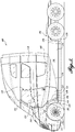
FIGURE 1 is a diagrammatical illustration of a semi-tractor having a lower door extension to cover access steps to a cab and a curved gap between the cab and chassis; -
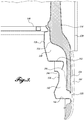
FIGURE 2 is a diagrammatical illustration of recessed steps and a lower door extension; -
FIGURE 3 is a cross sectional diagrammatical side view illustration of the recessed steps and lower door extension ofFIGURE 2 ; -
FIGURE 4 is a cross sectional diagrammatical top view illustration of the recessed steps and lower door extension ofFIGURE 2 ; -
FIGURE 5 is a diagrammatical illustration of a semi-tractor having a lower door extension to cover access steps to a cab and a curved gap between cab and chassis; -
FIGURE 6 is a diagrammatical illustration of a semi-tractor having a lower door extension to cover access steps to a cab and a curved gap between cab and chassis; and -
FIGURE 7 is a diagrammatical illustration of a semi-tractor having a lower door extension to cover access steps to a cab and a curved gap between cab and chassis. - Approximately half of the energy used to propel a long haul semi-tractor-trailer is expended to overcome aerodynamic drag. A significant portion of this drag is due to turbulent airflow around the lower sides of the vehicle. To reduce these turbulences, chassis fairings have been added to cover the fuel tanks and other chassis components.
- Cab access steps are required to enter the driver's cab. The cab access steps are typically placed in recesses in the chassis fairings and/or the steps are of reduced depth or they extend out from the fairing surface into the air stream. All of these configurations contribute to turbulent airflow rather than reduce it. In addition, some of these step designs can be difficult to use due to poor visibility and reduced size of the steps. The interface between the chassis fairings and the bottom of the cab is another area that contributes to the aerodynamic drag. This interface is typically a horizontal gap to allow for cab movement relative to the chassis. The gap is horizontal and therefore is in line with the airflow allowing air to be drawn underneath the cab or between the cab and chassis, and flow into the low pressure area between the cab back wall and the front of the trailer. This air impacts the front of the trailer, causing additional drag.
- In vehicles, such as semi-tractors, turbulence can be caused by the cab access steps, the transition from the front fender as it joins with the chassis fairing, and the interface between the cab and the chassis fairing. Aspects of the disclosed vehicles can address some of these issues.
- In some of the embodiments, a vehicle is provided with a gradual and smooth transition from the front fender to the cab door and chassis fairing. In some of the embodiments, a vehicle has steps that are covered with a lower door extension that requires no additional mechanisms or actuators to expose the steps when the door is opened. This configuration reduces the complexity and allows large, easy to see and use steps. In addition to the aerodynamic effects by concealing the steps, the lower door extension also shields the steps from road spray and provides increased security by making it difficult for carjackers to climb onto the cab.
- In some embodiments of the vehicles, aerodynamic performance is improved by providing curves and/or bends in the gap between the cab skirt and the chassis fairing. The angled configuration restricts the air from flowing into the gap and, therefore, directs more air around the vehicle to avoid the air hitting the front of the trailer.
- Referring to
FIGURE 1 , a semi-tractor 100 having alower door extension 124 to cover cab access steps leading to the inside of the cab102 and acurved gap 118 between thecab 102 andchassis 106 is illustrated. A semi-tractor is used as a representative vehicle to illustrate the various embodiments and is not meant to be limiting of the vehicles. - Semi-tractors can be distinguished from other vehicles by any one or more of the following features. It is to be appreciated that other vehicles, not normally considered semi-tractors, may also include one or more of these features as well. Semi-tractors may include three or more wheel axles, wherein one front axle is the steering axle, and one or both rear axles are drive axles. Semi-tractors may include a driver's cab enclosure that is supported on a suspension mechanism, in addition to the wheel suspension on the chassis. Therefore, the cab may move independently of the chassis. Semi-tractors may have the engine mounted generally in front of or underneath the cab. Semi-tractors may include cabs that are positioned above the engine and/or transmission. Semi-tractors may be capable of being repositioned from a riding position to an elevated position to allow access to the engine and/or transmission. Semi-tractors generally do not include a cargo box or cargo bed on the chassis, and instead include a hitch positioned forward of the rearmost wheel axel. This allows the semi-tractors to interchange trailers, or to be quickly decoupled from a trailer once the semi-tractor-trailer arrives at the unloading destination. Thus, allowing for more efficient handling of cargo transportation, as the semi-tractor need not wait for the trailer to be unloaded.
- In the embodiment of
FIGURE 1 , thevehicle 100 includes acab 102 supported over achassis 106. Not shown is the cab suspension mechanism that supports thecab 102 over thechassis 106. The cab suspension mechanism may allow thecab 102 andchassis 106 to move independently relative to each other. That is, thecab 102 may have additional suspension in order to provide a smoother ride for the driver. Thecab 102 may be described as the driver enclosure containing the driver's chair, steering wheel, and controls for operating the vehicle. Thecab 102 may be sealed to a certain extent from the exterior to prevent the intrusion of rain, road spray, cold or hot ambient air, and insects, for example. Thecab 102 is accessed via a door opening 120 on one or both lateral sides of thecab 102. Thedoor 104 is used to cover thedoor opening 120. The description herein is of a single lateral side of thevehicle 100, but it is to be appreciated that the opposite side is in all material respects similar to the side being described. - Referring to
FIGURE 2 , thedoor opening 120 may have arubberized seal 122 extending around the exterior of the door opening 120 circumference. Additionally, or alternatively, theseal 122 may be placed on the inside surface of thedoor 104. In some embodiments of thevehicle 100, thedoor 104 may include amain door portion 114 and a lowerdoor extension portion 124. Themain door portion 114 may be constructed from one or more exterior panels on a door frame. Themain door portion 114 is configured to include on the exterior, the door latch, the rearview mirror, the window frame, and window, for example. On the interior, as best seen inFIGURE 2 , themain door portion 114 includes aprotrusion 126 generally matching the size and configuration of the door opening 120 circumference. Theprotrusion 126 provides space for the window, controls, and the like. Theprotrusion 126 may also include a rubberized seal that cooperates with the immediately adjacent surface next to thedoor opening 120. Thedoor 104 includes alower door extension 124. Thelower door extension 124 is connected to the lower side of themain door portion 114. Thelower door extension 124 can be the portion of thedoor 104 that is lower than the lowermost edge of thedoor opening 120. Thelower door extension 124 may be, but is not necessarily, integral with themain door portion 114. Thelower door extension 124 may be constructed from the same exterior and interior panels as themain door portion 114, or thelower door extension 124 may be constructed from a distinct and separable exterior and interior panels. However, in some cases, thelower door extension 124 may overlap with themain door portion 114. - The
cab 102 further includes an exteriorcab side panel 128 that can be made from one or more panels. It is to be appreciated that reference to the exteriorcab side panel 128 includes reference to the plurality of the separate panels that may comprise it. Thepanel 128 surrounds the sides of thecab 102. The exteriorcab side panel 128 may extend to and/or extend beneath the elevation of thecab floor 168. In referring to the portion or portions of the exteriorcab side panel 128 that extend beneath the cab floor elevation, such exterior panel portions may be referred to as a "skirt" or "extension," such asextension 148 of the exteriorcab side panel 128. Any skirt orextension 148 of the exteriorcab side panel 128 may be integral with other panels or may be separate and distinct panels. Distinct panels may be advantageous in case the cab exterior is damaged and needs partial replacement. The exteriorcab side panel 128 may include the exterior side of thecab 102 not covered by thedoor 104, including themain door portion 114 andlower door extension 124, but not including parts of the roof, hood, bumper, and fender. - The
chassis 106 includes the underlying structural framework for supporting the main parts of thevehicle 100, including, but not limited to, thecab 102, engine (not shown), transmission (not shown), fuel tanks (not shown), wheel axles (not shown). Thechassis 106 may include two or more parallel frame rails (not shown) extending substantially from the front to the rear of thevehicle 100. The frame rails may be tied together by interconnecting tie rails connecting the two frame rails. Thechassis 106 may support abumper 132 at the front of thevehicle 100. Thechassis 106 can support afairing 134. The fairing 134 is provided to shield the chassis and to improve the aerodynamic properties of the vehicle. Thechassis fairing 134 extends from top to bottom covering the majority of the chassis. The fairing 134 also extends in the inboard to outboard direction. Thechassis fairing 134 can generally extend from the front wheel well 136 to the forward one of the tworear wheel wells 138. The fairing 134 can be a single piece fairing or assembled from two or more fairing pieces. It is to be appreciated that reference to chassis fairing 134 in the singular form also includes a fairing constructed from two or more fairing pieces. The fairing 134 may include afender portion 140 located immediately to the rear of thefront wheel 170. When viewed from the side, thefender portion 140 extends from front to back in an arc greater than the wheel radius. When viewed from the side, thefender portion 140 also extends outboard from thechassis 106 to about or slightly exceeding the outboard extension of thefront wheel 170. Thefender portion 140 has a curving surface as it recedes inboard into a recess 142 (best seen inFIGURE 2 ). Therecess 142 is generally an inboard formation of thefairing 134. That is, therecess 142 is pushed inboard with respect to the majority of thefairing 134. Thechassis fairing 134, including thefender 140 andrecess 142 can be rigidly connected to thechassis 106, which is independently movable from thecab 102 including thedoor 104 and exteriorcab side panel 128. Because thecab 102 should be allowed to move independent of thechassis 106, the fairing 134 (includingfender 140 and recess 142) is also independent from the exteriorcab side panel 128 and thedoor 104, at least to the extent that the exteriorcab side panel 128 and thedoor 104 move with thecab 102, while the fairing 134, which is connected to thechassis 106, does not. - Referring to
FIGURE 2 , therecess 142 is positioned to the rear of thefender 140 and forward of themain fairing portion 146. Themain fairing portion 146 can cover thechassis 106 beginning from the rear of thedoor 104 to the front of the rear wheel. Also seen inFIGURE 2 is anupper recess 150 placed to the rear of thefender 140. Thelower recess 142 andupper recess 150 are used for mounting a lower and upper cab access step, 144, 152, respectively, in the lower 142 andupper recess 150. However, thelower recess 150 is formed from thechassis fairing 134, and the upper recess is formed from the exteriorcab side panel 128. - Referring to
FIGURE 3 , thelower step 144 is seen more clearly resting on the horizontal surface built into therecess 142 formed from thechassis fairing 134. Thestep 144 can include a metal plate with a non-slip surface, such as perforations with upward extending rims. Theinboard side surface 194 of therecess 142 can extend upward and then curve under thelower edge 196 of the exteriorcab side panel 128, which forms theupper recess 150. When viewed from the side as inFIGURE 2 , therecess 150 follows the curve of thefender 140 as it extends adjacent to it, and then extends horizontally across to form a support for theupper step 152. Referring back toFIGURE 3 , the exteriorcab side panel 128 has an inboard side surface that extends upwards to thecab floor 168 to create the upperaccess step recess 150, and the exteriorcab side panel 128 also extends outboard to create a second horizontal surface andupper step 152, which then finishes in the curvedlower edge 196 adjacent to the inboard curvingside surface 194 of the lower recess. To allow for independent movement of thecab 102 relative to thechassis 106, thelower edge 196 of the exteriorcab side panel 128 is separated by a gap from the curvedinboard edge 194 of thefairing 134. Such gap can exist where the lower edge of the exteriorcab side panel 128 terminates adjacent to thechassis fairing 134. Thestep 152 can include a metal plate with a non-slip surface, such as perforations with upward extending rims. In some embodiments, the outboard edge of thelower step 144 may be offset or extend outboard from the outboard edge of theupper step 152. However, in other embodiments, the lower 144 and upper 152 steps may be at the same outboard location. In some embodiments, therecess 142 andlower step 144 are formed from the fairing 134 connected to thechassis 106, and therecess 150 andupper step 152 are formed from the exteriorcab side panel 128. However, in other embodiments, therecess 142 andlower step 144 may be formed from the exteriorcab side panel 128, or, in still other embodiments, therecess 150 andupper step 152 may be formed from thechassis fairing 134. That is, either or bothsteps cab side panel 128. - As seen in
FIGURE 2 , the doorlower extension 124 on the interior extends downward from themain door portion 114. The interface between thelower door extension 124 and themain door portion 114, on the interior, includes aridge 154 extending generally the width of thedoor 104. Theridge 154 continues downward below thecab floor 168 elevation, and fills a portion of therecess 150. Theridge 154 supports agooseneck hinge 156 through which thedoor 104 can be attached to thecab 102 at the front edge of thedoor 104. In the illustrated embodiment, thegooseneck hinge 156 is used as a lower hinge. This allows thedoor 104 to swing out over the outboard-extendingfender 140 as thedoor 104 is opened. Thegooseneck hinge 156 can be positioned below thecab floor 168 to prevent intrusion into the floor structure or interior space of thecab 102. A large recessed pocket can be provided below thecab floor 168 for thegooseneck hinge 156 to reside in when thedoor 104 is closed. Thegooseneck hinge 156 is used primarily because thefender 140 extends outboard from thecab 102 in the case when thecab 102 is narrower than the chassis 106 (when viewed from the front). As in the case just described, in some embodiments of thevehicle 100, the width of the majority of thecab 102 when viewed from the front can be less than the width of thechassis 106 and fairing 134 (except as noted herein). However, in other embodiments, the width of the majority of the cab 100 (when viewed from the front) may be same as the width of the chassis withfairing 134. - Referring to
FIGURE 2 , when viewed from the front, thelower door extension 124 extends outboard from themain door portion 114 to clear the outboard edge of theupper step 152. However, in other embodiments, such as when thecab 102 is made as wide as thechassis 106, thelower door extension 124 andmain door portion 114 can both extend outboard the same amount. Thelower door extension 124 extends below theupper step 152 to cover a majority of the loweraccess step recess 142 in thefairing 134. That is, there is an amount of vertical overlap of thelower door extension 124 with the chassis fairing 134 that is enough to cover a majority of thelower recess 142. Thelower door extension 124 therefore presents a smooth outboard surface for airflow to improve the aerodynamics of thevehicle 100. In some embodiments, the lower edge of thelower door extension 124 extends outboard to match the outboard edge of thelower step 144, but is above the horizontal upper surface of thelower step 144. The distance between the lower edge of thelower door extension 124 and the upper surface of thelower step 144 forms thegap 118, which will be described in more detail below. Thegap 118 may only be wide enough to permit thecab 102 andlower door extension 124 to travel on the cab suspension without thelower door extension 124 hitting the top of thelower step 144. - Referring to
FIGURE 1 , it can be seen that thelower door extension 124 extends sufficiently to conceal at least the upperaccess step recess 150 andupper step 152 and a majority of the loweraccess step recess 142, while the outboard edge of thelower step 144 remains visible. Because of thelower door extension 124 extending outboard, the lower and upper steps can be offset from each other in a more ergonomically acceptable manner. Furthermore, concealment of the steps by thelower door extension 124 reduces the aerodynamic drag that would be created by therecesses - Referring again to
FIGURE 1 , in some embodiments of thevehicle 100, a non-horizontal, angled, orcurved gap 118 is created between the lowermost edges of the exteriorcab side panel 128 anddoor 104 and thechassis fairing 134. Rather than separating the cab from the chassis with a horizontal gap extending from front to rear of the cab, wherein such horizontal gap is near the top of the chassis frame rails as is commonly done, some embodiments of thevehicle 100 disclosed herein have thegap 118 that varies in elevation when separating the lower edge of the exteriorcab side panel 128 anddoor 104 from thechassis fairing 134. Thegap 118 can be a series of interconnecting gap sections. - In some embodiments, a
visible gap 118 extends from the front wheel well 136 to the rear end of thecab 102. Thegap 118 is needed to allow movement of thecab 102 in relation to thechassis 106. The gap corresponds generally to and can be slightly larger than the allowed suspension travel between thecab 102 andchassis 106 to avoid the lower edge of the exteriorcab side panel 128 anddoor 104 hitting thechassis fairing 134. In some embodiments, where the door leading edge ends adjacent to thefender 140 to create thegap 118, the leading edge can be curved inboard. In some embodiments, where thechassis fairing 134 is provided adjacent to the lower edge of the exteriorcab side panel 128 at thegap 118, the chassis fairing 134 can be curved inboard. - As seen in
FIGURE 1 , thegap 118 can include agap section 182 that begins at an elevation near the top of the frame rails at the front of thecab 102. Thegap section 182 is essentially horizontal or slightly angled down, and traverses the top of thefender 140, and the hood section in front of thedoor 104. Thehorizontal gap section 182 connects to agap section 180 that is created by theleading edge 158 of thelower door extension 124 and therear section 172 of thefender 140, as best seen inFIGURE 4 . Thegap section 180 created by thefender 140 and theleading edge 158 of thelower door extension 124, when viewed from the side, generally arcs downwardly to an elevation corresponding to the height of the upper surface of thelower step 144. Thegap section 180 then makes a 90 degree turn toward the rear of thecab 102 and connects with thegap section 118 described above separating the lower edge of the doorlower extension 124 and the upper surface of thelower step 144. Behind the rear of the doorlower extension 124, thegap 118 makes a soft curve upward. This section of thegap 118 is formed by the lower edge of the exterior cabside panel extension 148 that is mounted on thecab 102 and to the rear of thelower door extension 124, but separated from thelower door extension 124. The exterior cabside panel extension 148 is below thecab floor 168. The exterior cabside panel extension 148 is also extended outboard at a lower portion thereof to match the exterior surface of the doorlower extension 124. The exterior cabside panel extension 148 curves outboard to inboard to join with the remainder of the exteriorcab side panel 128. Thegap 118 continues to rise slightly past the exterior cabside panel extension 148, and then thegap 118 levels off, and then continues substantially horizontally to the end of the rear of thecab 102. This rear section of thegap 118 is created by the lower edge of the exteriorcab side panel 128 and thechassis fairing 134. - The
gap 118 as described above is achieved generally by extending the bottom of thedoor 104 via the doorlower extension 124 and the exteriorcab side panel 128 via theside panel extension 148 down to the gap location. The door and cab extensions are not only extended to be lower, but are also extended outboard so that the surface of the outboard extension of the front fender surfaces to the door and cab provide a smooth transition for air flowing across the side of the vehicle. That is, the outboard surfaces of thelower door extension 124, thefender 140, the exterior cabside panel extension 148, and the chassis fairing 134 can be substantially coplanar with each other. Coplanar outboard surfaces means that the smooth cab side profile is presented to the air flowing around the side of the cab. - As can be appreciated from the description of the
gap 118, the majority of thegap 118 is not horizontal. Instead, thegap 118 includes one or more curves or is at an angle greater than 0 degrees with respect to horizontal. Thecurved gap 118 provides an aerodynamic benefit. In conventional cab enclosures, the cab is separated from the chassis via a horizontal gap which is in line with the direction of airflow. That is, the air flowing by the sides of the cab is horizontal, and the angle between the direction of airflow and the horizontal gap is essentially 0 degrees. This allows air to be drawn into the horizontal gap and causes additional drag by hitting the front of the trailer. With an angled gap having one or more sections that are at an angle greater than 0 degrees with respect to horizontal, the airflow crosses the gap rather than flowing into it. This reduces the volume of air being drawn into the low pressure area between the rear of the cab and the front of the trailer, thereby reducing the aerodynamic drag. Thus, by making the gap between the cab and the chassis have angles of greater than 0 degrees with respect to the air flowing around the cab, such that the air flow and gap are not aligned in the same direction, the aerodynamic performance may be improved. Furthermore, the gap can be as wide or slightly wider than the distance that the cab suspension system may travel. - Referring to
FIGURE 4 , other aspects for improving the aerodynamics of thevehicle 100 will be described. Thefender 140 is extended outboard, and the exterior surface of thelower door extension 134 is also similarly extended outboard to match the outboard extension of the exterior surface of thefender 140. That is, the outboard surface of thefender 140 is coplanar with the outboard surface of thelower door extension 124. Additionally, thefender 140, which is formed from thechassis fairing 134, curves inboard at therear end 172 to form thelower step recess 142. Thelower door extension 124 has aleading edge 158 that when viewed from the top as inFIGURE 4 , is curved inboard of the outboard extension of thefender 140, while thefender 140 recedes inboard. Thelower door extension 124 while being separated from thechassis 106 acts as a continuation of thefront fender 140 exterior surface, thus providing a smooth transition for air flowing across thevehicle 100. Also, the frontleading edge 174 of thefender 140 is curved inboard, as best seen inFIGURE 4 , to reduce turbulence of air flowing across the front wheel. The vehicle's 100 aerodynamics are further improved by the inboard curvature of the chassis fairing 134 atlocation 162, as best seen inFIGURE 4 . The inboard curvature atlocation 162 reduces turbulence of the air flowing across a section of the exterior cabside panel extension 148. Similar to the leading edge of the lower door extension, when thechassis fairing 134 meets the edge of thegap 118 the chassis fairing 134 can curve inboard as shown inFIGURE 4 atlocation 162 where it recedes behind the exterior cabside panel extension 148. This inboard curvature, like the lower door extension leading edge curvature, aids in the reattachment of the air flowing across the cabside panel extension 148 and prevents additional tripping of the airflow. Similar inboard curvature of the fairing 134 can be provided along thegap 118, where the exteriorcab side panel 128 extends down to thegap 118, and the fairing 134 recedes behind thepanel 128. The inboard curvature of thefront fender 140 atlocation 174, the inboard curvature of thelower door extension 124 atlocation 158, and the inboard curvature of the chassis fairing 134 atlocation 162 allow the reattachment of the airflow coming off the front wheel opening in the case of thefender 140 and to the rear of thedoor 104. The inboard curvature prevents the leading edges of thefender 140,lower door extension 124, and fairing 134 from catching or tripping the air, which would cause increased turbulence and increased drag. - Referring to
FIGURE 5 , another embodiment of avehicle 100 is illustrated where like numbers represent like parts as those illustrated inFIGURE 1 , except for the changes noted below. In the embodiment ofFIGURE 5 , however, thegap 218 has a different configuration than thegap 118 illustrated inFIGURE 1 . InFIGURE 5 , instead of the gap having a horizontal section at the rear of the cab as inFIGURE 1 , thegap 218 is essentially an angled line extending from the rear of thelower door extension 124 to the rear of thecab 102 to minimize any horizontal sections of gap. Thegap 218 is created by extending the lower edge of the exteriorcab side panel 128 to give a straight upward sloping profile, and adding a corresponding inboard curvature to the chassis fairing 134 to allow the lower edge of the exteriorcab side panel 128 to extend lower and outboard to be coplanar with thelower door extension 124 andfender 140. In one embodiment, the exteriorcab side panel 128 can extend to the lower edge of the vehicle, which may eliminate the need for a chassis fairing. - Referring to
FIGURE 6 , another embodiment of avehicle 100 is illustrated where like numbers represent like parts as those illustrated inFIGURE 1 , except for the changes noted below. Thevehicle 100 ofFIGURE 6 has a lower door extension 224 that extends past the outboard edge of thelower step 144. The outboard edge of thelower step 114 may be brought inboard to allow the lower door extension 224 to extend past the outboard edge of thelower step 144. This hides the outboard edge of thestep 144 behind the lower door extension 224. Thelower step 144 can be moved inboard, or thefender 140, the lower door extension 224, and the exteriorcab side panel 128 can be extended further outboard. The lower door extension 224 may even be extended to eliminate any gap below the lower door extension 224. Thechassis fairing 134 may be provided with an inboard curvature at the lower door extension to permit the door to extend below thelower step 144. - Referring to
FIGURE 7 , another embodiment of avehicle 100 is illustrated where like numbers represent like parts as those illustrated inFIGURE 1 , except for the changes noted below. In the embodiment ofFIGURE 1 , agap 180 is present between thefender 140 and theleading edge 158 of thelower door extension 124. In the embodiment ofFIGURE 7 , thegap 180 has been eliminated by moving theleading edge 158 of thelower door extension 324 forward to occupy the area previously occupied by thefender 140. That is, thelower door extension 324 may be shaped to include a fender, or the fender extending from the chassis fender may be hidden beneath thelower door extension 324. - In some embodiments of the
vehicle 100, thevehicle 100 includes acab 102 having a door opening 120 on a side thereof, achassis 106 that supports thecab 102, two ormore steps door opening 120, each of which is supported by thecab 102 or thechassis 106, wherein the two or more steps are placed within one ormore recesses cab 102 orchassis 106, and adoor 104 connected to thecab 102, wherein thedoor 104 fits within thedoor opening 120, and thedoor 104 comprises alower door extension lowermost step 144, thelower door extension more recesses lower door extension fender 140 or exterior cabside panel extension 148 to provide a coplanar transition from thefender 140 to thedoor 104, or from thedoor 104 to the exterior cabside panel extension 148, or both. - The
vehicle 100 may further include agap 118 created between a lowermost edge of an exteriorcab side panel 128 on thecab 102 and a fairing 134 on thechassis 106, wherein thegap 118 extends along the side of thecab 102 and chassis fairing 134 at least from the rear of thelower door extension cab 102, and thegap 118 is angled greater than 0 degrees with respect to a horizontal direction for at least a majority of the length of thegap 118. - The
vehicle 100 may include agap 118, the width of thegap 118 is sized to approximately match the distance that thecab 102 may travel with respect to thechassis 106. - The vehicle's 100
chassis 106 may include afender 140 that extends outboard, alower door extension 124, 224 that extends outboard to match the outboard extension of thefender 140, and theleading edge 158 of thelower door extension 124, 224 is curved inboard where thefender 140 recedes behind thelower door extension 124, 224. For example, thefender 140 is constructed so that the rear side of thefender 140 recedes behind theleading edge 158 of thedoor 104 in an arc. - The
vehicle 100 may include afender 140, alower door extension 124, 224, an exterior cabside panel extension 148, and achassis fairing 134, such that the outboard extensions of each are coplanar. Coplanar outboard surfaces of any two or more of these pieces assist in reducing air turbulence and drag as the air flows over the cab side. - The vehicle's 100
cab 102 may include aside panel 148 separable from and placed to the rear of thelower door extension door 104 and extends outboard to be coplanar with thelower door extension - The vehicle's 100
cab 102 may include an exteriorcab side panel chassis fairing 134, and the chassis fairing 134 curves inboard at a location, such aslocation 162 inFIGURE 4 , where thechassis fairing 134 recedes behind the exteriorcab side panel - The vehicle's
cab 102 may include arecess 150 comprising anupper step 152, and thechassis 106 may include arecess 142 comprising alower step 144. However, either thecab 102 or thechassis 106 may include both an upper andlower recess - The
vehicle 100 has arecess 150 for theupper step 152 that is formed from an exteriorcab side panel 128, and therecess 142 for thelower step 144 is formed from a fairing 134 supported on thechassis 106. - The vehicle's 100 chassis fairing 134 includes a
front fender portion 140, arecess portion 142 for astep 144, and amain fairing 146 for thechassis 106. The main fairing portion generally extends from behind thedoor 104 to the front of the first rear wheel. - The vehicle's 100
cab 102 can move independently from thechassis 106. Accordingly, anangled gap 118 may be necessary to provide for movement between thecab 102 andchassis 106, such that thecab 102 will not hit parts of thechassis 106 when thecab 102 travels. - The
vehicle 100 can be a semi-tractor. - In some embodiments of the
vehicle 100, thevehicle 100 may include acab 102 having an exteriorcab side panel 128, achassis 106 that supports thecab 102, wherein thecab 102 can move independently of thechassis 106, and wherein thechassis 106 has afairing 134, and the exteriorcab side panel gap 118 that allows thecab 102 to move independent of thechassis 106 without hitting thechassis fairing 134, wherein the gap separates the lower edge from the chassis fairing, and the gap has an angle greater than 0 with respect to a horizontal direction. - In the
vehicle 100, thegap 118 can extend from behind thedoor 104 to the rear of thecab 102. - The
vehicle 100 can have an exteriorcab side panel chassis 106 can extend outboard, and the outboard extension of the exteriorcab side panel chassis fairing 134. - The
vehicle 100 can have achassis fairing 134 that is curved inboard at thelocation 162 where thechassis fairing 134 recedes behind the exteriorcab side panel - In addition to vehicles, methods for reducing the aerodynamic drag of the
vehicle 100 are described. - In one embodiment, a method for reducing the aerodynamic drag of the
vehicle 100 includes providing adoor 104 to the rear of afender 140, wherein thedoor 104 has aleading edge 158 that curves inboard along the rear of thefender 140 where thefender 140 recedes behind theleading edge 158 of thedoor 104. - In one embodiment, a method for reducing the aerodynamic drag of the
vehicle 100 includes providing an exteriorcab side panel chassis fairing 134 and providing aninboard curvature 162 on the chassis fairing 134 where thechassis fairing 134 recedes behind the exteriorcab side panel - In one embodiment, a method for reducing the aerodynamic drag of the
vehicle 100 includes providing afender 140 that extends outboard, providing alower door extension 124, 224 that extends outboard, and a majority of thefender 140 and a majority of thelower door extension 124, 224 are coplanar. - In one embodiment, a method for reducing the aerodynamic drag of the
vehicle 100 includes providing alower step 144 within arecess 142 formed in achassis fairing 134, providing anupper step 152 within arecess 150 formed in an exteriorcab side panel 128, wherein thechassis fairing 134 is supported from achassis 106, and the exteriorcab side panel 128 is supported by thecab 102 that moves independent of thechassis 106, and providing alower door extension lower step recess 142, and theupper step recess 150, and thelower door extension fender 140, the outboard surface of the exteriorcab side panel 148, or thechassis fairing 134. - In one embodiment, a method for reducing the aerodynamic drag of the
vehicle 100 includes providing adoor 104 wherein theleading edge 158 of thedoor 104 extends to adjacent the rear of thefront wheel 170 and arcs in a manner corresponding to the wheel radius, such that theleading edge 158 of thedoor 104 may form a fender for thefront wheel 170. - In one embodiment, a method for reducing the aerodynamic drag of the
vehicle 100 includes providing an exteriorcab side panel 128 on thecab 102, and a fairing 134 on thechassis 106, wherein the lower edge of the exteriorcab side panel 128 is separated from the fairing 134 by agap 118, and thegap 118 extends from behind thedoor 104 of thevehicle 100 to the rear of thecab 102, and thegap 118 is at an angle greater than 0 with respect to a horizontal direction for all or a majority of the length of thegap 118. In one embodiment, the angle can even be 90 degrees with respect to the horizontal direction, in which case thegap 118 is present as a vertical gap, and is positioned at or near thecab 102 rear. - The methods for reducing the aerodynamic drag of the
vehicle 100 may be combined into a single method. That is, all the ways of reducing the aerodynamic drag may be applied to any onevehicle 100. Additionally, thevehicle 100 of the foregoing methods can include afender 140 that is formed on a fairing 134 supported on achassis 106, and thedoor 104 is supported by acab 102, wherein thecab 102 moves independently from thechassis 106, and theleading edge 158 of thedoor 104 and thefender 104 are separated by agap 180 that is approximately the size of the amount of movement allowed between thecab 102 andchassis 106.
Claims (13)
- A vehicle (100), comprising:a cab (102) having a door opening (120) on a side thereof;a chassis (106) that supports the cab (102);two or more steps (144, 152) leading to the door opening (120), each of which is supported by the cab (102) or the chassis (106), wherein the two or more steps (144, 152) are placed within one or more recesses (142, 150) in the cab (102) or chassis (106); anda door (104) connected to the cab (102), wherein the door (104) fits within the door opening (120), and the door (104) comprises a lower door extension (124) having a lower edge that terminates near to an upper surface of a lowermost step (144), the lower door extension (124) covers a majority of the one or more recesses (142, 150), and the lower door extension (124) extends outboard to match the outboard extension of a fender (140) or exterior cab side panel (128) to provide a coplanar transition from the fender (140) to the door (104), or from the door (104) to the exterior cab side panel (128), or both,characterized in that a gap is created between a lowermost edge (196) of an exterior cab side panel (128) on the cab (102) and a fairing (134) on the chassis (106), wherein the gap extends along the side of the cab and chassis fairing (134) at least from the rear of the lower door extension (124) to an end of the cab (102), and the gap is angled greater than 0 degrees with respect to a horizontal direction.
- The vehicle (100) of Claim 1, wherein the chassis (106) includes the fender (140) that extends outboard, the lower door extension (124) extends outboard to match the outboard extension of the fender (140), and the leading edge of the lower door extension (124) is curved inboard where the fender (140) recedes behind the lower door extension (124).
- The vehicle (100) of Claim 2, wherein the outboard extensions of the fender (140), the lower door extension (124), and the chassis fairing (134) are coplanar.
- The vehicle (100) of Claim 1, wherein a width of the gap is sized to approximately match the distance that the cab (102) may travel with respect to the chassis (106).
- The vehicle (100) of Claim 1, wherein the cab (102) further comprises a side panel (148) separable from and placed to the rear of the lower door extension (124), and that is juxtaposed next to the door (104) and extends outboard to be coplanar with the lower door extension (124).
- The vehicle (100) of Claim 1, wherein the cab (102) includes an exterior cab side panel (128) that extends below the top of the chassis fairing (134), and the chassis fairing (134) curves inboard where the chassis fairing (134) recedes behind the exterior cab side panel (128).
- The vehicle (100) of Claim 1, wherein the cab (102) includes a recess (150) comprising an upper step (152), and the chassis (106) includes a recess (142) comprising a lower step (144).
- The vehicle (100) of Claim 7, wherein the recess (150) for the upper step (152) is formed from an exterior cab side panel (128) and the recess (142) for the lower step (144) is formed from a fairing (134) supported on the chassis (106).
- The vehicle (100) of Claim 1, wherein the chassis fairing (134) includes a front fender portion, a recess portion (150) for a step, and a main fairing for the chassis (106).
- The vehicle (100) of Claim 1, wherein the cab (102) can move independently from the chassis (106).
- The vehicle (100) of Claim 1, wherein the vehicle (100) is a semi-tractor.
- A method for reducing aerodynamic drag of a vehicle (100) comprising a cab (102) independently movably supported from a chassis (106), the method comprising:providing a door (104) rearward of a fender (140), wherein the door (104) has a leading edge that curves inboard where the fender (140) recedes behind the leading edge of the door (104), wherein the fender (140) extends outboard, andproviding a lower door extension (124) that extends outboard, wherein a majority of the fender (140) and a majority of the lower door extension (124) are coplanar, and, the fender (140) is formed on a fairing (134) supported on the chassis (106) and the door (104) is supported by the cab (102), the cab (102) moving independently from the chassis (106),characterized in that the method further comprisesproviding an outboard surface of the door (104) which is coplanar with an outboard surface of the fender (140) with the leading edge of the door (104) and the trailing edge of the fender (140) separated by a gap to allow movement between the cab (102) and chassis (106), the gap being approximately the size of the amount of movement allowed between the cab (102) and the chassis (106).
- The method of Claim 12, further comprising providing an exterior cab side panel (128) that extends below the chassis fairing (134), and providing an inboard curvature on the chassis fairing (134) wherein the chassis fairing (134) recedes behind the exterior cab side panel (128).
Priority Applications (2)
| Application Number | Priority Date | Filing Date | Title |
|---|---|---|---|
| EP16205662.6A EP3176038B1 (en) | 2013-03-06 | 2014-03-04 | Recess steps for cab access |
| EP18214394.1A EP3489089B1 (en) | 2013-03-06 | 2014-03-04 | Recess steps for cab access and method for reducing the aerodynamic drag of a vehicle |
Applications Claiming Priority (2)
| Application Number | Priority Date | Filing Date | Title |
|---|---|---|---|
| US13/787,511 US8899659B2 (en) | 2013-03-06 | 2013-03-06 | Recess steps for cab access |
| PCT/US2014/020327 WO2014138069A1 (en) | 2013-03-06 | 2014-03-04 | Recess steps for cab access |
Related Child Applications (3)
| Application Number | Title | Priority Date | Filing Date |
|---|---|---|---|
| EP18214394.1A Division EP3489089B1 (en) | 2013-03-06 | 2014-03-04 | Recess steps for cab access and method for reducing the aerodynamic drag of a vehicle |
| EP16205662.6A Division EP3176038B1 (en) | 2013-03-06 | 2014-03-04 | Recess steps for cab access |
| EP16205662.6A Division-Into EP3176038B1 (en) | 2013-03-06 | 2014-03-04 | Recess steps for cab access |
Publications (2)
| Publication Number | Publication Date |
|---|---|
| EP2964488A1 EP2964488A1 (en) | 2016-01-13 |
| EP2964488B1 true EP2964488B1 (en) | 2017-10-04 |
Family
ID=50288347
Family Applications (3)
| Application Number | Title | Priority Date | Filing Date |
|---|---|---|---|
| EP16205662.6A Active EP3176038B1 (en) | 2013-03-06 | 2014-03-04 | Recess steps for cab access |
| EP14710768.4A Active EP2964488B1 (en) | 2013-03-06 | 2014-03-04 | Recess steps for cab access |
| EP18214394.1A Active EP3489089B1 (en) | 2013-03-06 | 2014-03-04 | Recess steps for cab access and method for reducing the aerodynamic drag of a vehicle |
Family Applications Before (1)
| Application Number | Title | Priority Date | Filing Date |
|---|---|---|---|
| EP16205662.6A Active EP3176038B1 (en) | 2013-03-06 | 2014-03-04 | Recess steps for cab access |
Family Applications After (1)
| Application Number | Title | Priority Date | Filing Date |
|---|---|---|---|
| EP18214394.1A Active EP3489089B1 (en) | 2013-03-06 | 2014-03-04 | Recess steps for cab access and method for reducing the aerodynamic drag of a vehicle |
Country Status (7)
| Country | Link |
|---|---|
| US (1) | US8899659B2 (en) |
| EP (3) | EP3176038B1 (en) |
| AU (1) | AU2014226024B2 (en) |
| CA (1) | CA2902489C (en) |
| ES (1) | ES2906861T3 (en) |
| MX (1) | MX361356B (en) |
| WO (1) | WO2014138069A1 (en) |
Cited By (1)
| Publication number | Priority date | Publication date | Assignee | Title |
|---|---|---|---|---|
| WO2022005285A1 (en) | 2020-07-02 | 2022-01-06 | Daf Trucks N.V. | A vehicle |
Families Citing this family (29)
| Publication number | Priority date | Publication date | Assignee | Title |
|---|---|---|---|---|
| US6834875B2 (en) | 2001-10-16 | 2004-12-28 | American Moto Products, Inc. | Retractable vehicle step |
| US9701249B2 (en) | 2006-10-27 | 2017-07-11 | Lund Motion Products, Inc. | Retractable vehicle step |
| US11926286B2 (en) | 2011-10-31 | 2024-03-12 | Lund Motion Products, Inc. | Retractable vehicle step |
| US9156406B2 (en) | 2013-09-27 | 2015-10-13 | Lund, Inc. | Modular rail and step system |
| US9656698B2 (en) * | 2014-05-07 | 2017-05-23 | Firestone Industrial Products Company, Llc | Moveable cab fairings |
| US9145092B1 (en) | 2014-10-02 | 2015-09-29 | Pink Adventure Group, Inc. | Side entry vehicle systems and related components |
| US9463745B2 (en) | 2014-10-02 | 2016-10-11 | Pink Adventure Group, Inc. | Side entry vehicle systems and related components |
| US9126535B1 (en) * | 2014-12-12 | 2015-09-08 | Ford Global Technologies, Llc | Fender step for pick-up trucks |
| US9550458B2 (en) | 2015-06-05 | 2017-01-24 | Lund Motion Products, Inc. | Retractable step and side bar assembly for raised vehicle |
| US9522634B1 (en) | 2015-06-05 | 2016-12-20 | Lund Motion Products, Inc. | Horizontal retractable vehicle step |
| US10618472B2 (en) | 2015-08-04 | 2020-04-14 | T-Max (Hangzhou) Technology Co., Ltd. | Vehicle and vehicle step apparatus with multiple drive motors |
| DE102015010657A1 (en) * | 2015-08-14 | 2017-02-16 | Man Truck & Bus Ag | Side covering device for a commercial vehicle |
| FR3043956B1 (en) * | 2015-11-23 | 2018-05-11 | Renault S.A.S | DOOR THRESHOLD FOR MOTOR VEHICLE WITH INTEGRATED FOOTBOARD. |
| USD826817S1 (en) * | 2017-04-10 | 2018-08-28 | Volvo Lastvagnar Ab | Body part for vehicle |
| WO2018215810A1 (en) * | 2017-05-22 | 2018-11-29 | Volvo Truck Corporation | An industrial vehicle cab comprising a step lighting system, a body component with a lighting system, and associated industrial vehicle |
| USD891340S1 (en) * | 2017-10-17 | 2020-07-28 | Paccar Inc | Vehicle roof fairing |
| JP6971381B2 (en) * | 2018-03-29 | 2021-11-24 | 本田技研工業株式会社 | Saddle-type electric vehicle |
| US11813930B2 (en) | 2018-05-31 | 2023-11-14 | Oshkosh Corporation | Vehicle door and window arrangement |
| US10384614B1 (en) | 2018-07-20 | 2019-08-20 | T-Max (Hangzhou) Technology Co., Ltd. | Vehicle, running board assembly and drive assembly for running board |
| US11198394B2 (en) | 2018-07-20 | 2021-12-14 | T-Max (Hangzhou) Technology Co., Ltd. | Vehicle running board apparatus and retractable device thereof |
| CN110012061B (en) | 2019-02-20 | 2022-02-08 | 杭州天铭科技股份有限公司 | Management device for vehicle equipment, vehicle, and server |
| WO2020177186A1 (en) | 2019-03-05 | 2020-09-10 | 杭州天铭科技股份有限公司 | Vehicle step bar device and vehicle |
| WO2020181617A1 (en) | 2019-03-11 | 2020-09-17 | 杭州天铭科技股份有限公司 | Adjustment apparatus, adjuster, and shock absorber |
| US11584387B2 (en) | 2019-09-16 | 2023-02-21 | T-Max (Hangzhou) Technology Co., Ltd. | Step apparatus for vehicle and vehicle |
| WO2021227617A1 (en) | 2020-05-11 | 2021-11-18 | 杭州天铭科技股份有限公司 | Vehicle pedal apparatus and vehicle |
| WO2021227616A1 (en) | 2020-05-11 | 2021-11-18 | 杭州天铭科技股份有限公司 | Vehicle footboard device and vehicle |
| DE102022100114A1 (en) * | 2021-01-05 | 2022-07-07 | Dana Heavy Vehicle Systems Group, Llc | cabin isolation system |
| GB2614298A (en) * | 2021-12-23 | 2023-07-05 | Daimler Ag | Arrangement of a side door on a cab for a commercial vehicle |
| CN115303369B (en) * | 2022-09-19 | 2023-12-08 | 中国重汽集团济南动力有限公司 | Light truck tire enclosure device |
Family Cites Families (30)
| Publication number | Priority date | Publication date | Assignee | Title |
|---|---|---|---|---|
| US2163323A (en) * | 1938-01-14 | 1939-06-20 | Earl E Howe | Hinge mechanism |
| US2404870A (en) * | 1941-07-17 | 1946-07-30 | Budd Edward G Mfg Co | Body for vehicles, especially for pleasure automobiles |
| DE1020534B (en) | 1956-04-21 | 1957-12-05 | Kloeckner Humboldt Deutz Ag | Motor vehicle with a closed body |
| US3887227A (en) * | 1968-11-02 | 1975-06-03 | Daimler Benz Ag | Installation for the protection of motor vehicle bodies against lateral impacts |
| DE3644959C2 (en) | 1986-05-28 | 1994-03-03 | Man Nutzfahrzeuge Ag | Front flap opening and closing mechanism for a front wall part hinged to the driver's cab of a front steering truck |
| US4836568A (en) | 1987-09-14 | 1989-06-06 | Paccar Inc. | Aerodynamically streamlined step assembly for a truck |
| IT8867877A0 (en) * | 1988-09-30 | 1988-09-30 | Iveco Fiat | SERIES OF CABINS FOR HEAVY VEHICLES |
| US4925235A (en) * | 1989-08-25 | 1990-05-15 | Paccar Inc | Cab fairing mounting for truck |
| US5092617A (en) | 1990-12-31 | 1992-03-03 | Jones Jr Harvey | Truck cab accessory step apparatus |
| US5257847A (en) | 1992-07-10 | 1993-11-02 | Pacific Auto Accessories, Inc. | Shrouded truck step kit |
| US5538265A (en) | 1995-01-12 | 1996-07-23 | Navistar International Transportation Corp. | Retractable step for a truck |
| US5806869A (en) * | 1996-02-13 | 1998-09-15 | Richards; Robert H. E. | Protected step conversion kit |
| US5947520A (en) | 1996-06-27 | 1999-09-07 | Freightliner Corporation | Vehicle with sacrificial fairing |
| US6179312B1 (en) | 1997-03-14 | 2001-01-30 | Freightliner Llc | Retractable stairway for entering and exiting a vehicle |
| USD434348S (en) | 2000-01-20 | 2000-11-28 | Paccar Inc | Exterior surface configuration of a fuel tank fairing for a truck |
| US6736447B2 (en) | 2002-03-19 | 2004-05-18 | Paccar Inc | Ducted aerodynamic front section of a vehicle |
| DE102004024694B4 (en) | 2004-05-19 | 2007-02-15 | Daimlerchrysler Ag | Body for a vehicle |
| US7168722B1 (en) | 2004-08-23 | 2007-01-30 | Piotrowski Leo D | Pull-out step assembly for a pickup truck |
| USD539704S1 (en) | 2005-09-12 | 2007-04-03 | Paccar Inc | Truck body |
| USD563281S1 (en) | 2005-09-12 | 2008-03-04 | Paccar Inc | Truck body |
| USD532731S1 (en) | 2005-09-12 | 2006-11-28 | Paccar Inc | Truck rear chassis fairing |
| USD561647S1 (en) | 2005-09-12 | 2008-02-12 | Paccar Inc | Truck body |
| JP2009535534A (en) | 2006-04-26 | 2009-10-01 | ボルボ ラストバグナー アーベー | Vehicle entrance system |
| USD549146S1 (en) | 2007-02-01 | 2007-08-21 | Paccar Inc. | Vehicle access step |
| US7578546B2 (en) | 2007-03-20 | 2009-08-25 | International Truck Intellectual Property Company, Llc | Removable chassis skirt |
| USD570253S1 (en) | 2007-04-18 | 2008-06-03 | X Chevron Commercial Inc. | Truck body |
| USD607395S1 (en) | 2009-08-03 | 2010-01-05 | Mahindra Navistar Automotives Limited | Step closeout of a truck vehicle |
| USD632224S1 (en) | 2010-04-28 | 2011-02-08 | Paccar Inc | Truck body |
| US8424956B2 (en) | 2010-09-03 | 2013-04-23 | Cvg Management Corporation | Aerodynamic wheel cover |
| DE102011106220B3 (en) | 2011-06-07 | 2012-06-21 | Georg Bunkowski | Storage device for use in e.g. driver door of cab of lorry to store shoe of driver, has receiving unit comprising hole-type connector for attachment to steps at cab such that unit is arranged between steps at cab |
-
2013
- 2013-03-06 US US13/787,511 patent/US8899659B2/en active Active
-
2014
- 2014-03-04 WO PCT/US2014/020327 patent/WO2014138069A1/en active Application Filing
- 2014-03-04 EP EP16205662.6A patent/EP3176038B1/en active Active
- 2014-03-04 EP EP14710768.4A patent/EP2964488B1/en active Active
- 2014-03-04 EP EP18214394.1A patent/EP3489089B1/en active Active
- 2014-03-04 CA CA2902489A patent/CA2902489C/en active Active
- 2014-03-04 ES ES18214394T patent/ES2906861T3/en active Active
- 2014-03-04 MX MX2015011159A patent/MX361356B/en active IP Right Grant
- 2014-03-04 AU AU2014226024A patent/AU2014226024B2/en active Active
Non-Patent Citations (1)
| Title |
|---|
| None * |
Cited By (2)
| Publication number | Priority date | Publication date | Assignee | Title |
|---|---|---|---|---|
| WO2022005285A1 (en) | 2020-07-02 | 2022-01-06 | Daf Trucks N.V. | A vehicle |
| NL2025976B1 (en) | 2020-07-02 | 2022-03-08 | Daf Trucks Nv | A vehicle. |
Also Published As
| Publication number | Publication date |
|---|---|
| ES2906861T3 (en) | 2022-04-20 |
| CA2902489A1 (en) | 2014-09-12 |
| EP3489089A1 (en) | 2019-05-29 |
| MX2015011159A (en) | 2016-04-25 |
| AU2014226024A1 (en) | 2015-10-22 |
| US20140252798A1 (en) | 2014-09-11 |
| EP3176038B1 (en) | 2019-01-30 |
| EP2964488A1 (en) | 2016-01-13 |
| MX361356B (en) | 2018-12-04 |
| EP3489089B1 (en) | 2021-12-08 |
| AU2014226024B2 (en) | 2015-10-29 |
| EP3176038A1 (en) | 2017-06-07 |
| US8899659B2 (en) | 2014-12-02 |
| CA2902489C (en) | 2016-05-03 |
| WO2014138069A1 (en) | 2014-09-12 |
Similar Documents
| Publication | Publication Date | Title |
|---|---|---|
| EP2964488B1 (en) | Recess steps for cab access | |
| US9308949B1 (en) | Systems and methods for reducing drag on a vehicle or vehicle combination | |
| US7806464B2 (en) | Fairing for a trailer | |
| US6932419B1 (en) | Aerodynamic guiding arrangements for vehicles | |
| US8491036B2 (en) | Devices and methods for reducing vehicle drag | |
| US8684447B2 (en) | Devices and methods for reducing vehicle drag | |
| US20110204677A1 (en) | Dam skirt aerodynamic fairing device | |
| US20150217814A1 (en) | Multicomponent improved vehicle fuel economy system | |
| CN100465031C (en) | Attachment structure for tonneau cover for pickup truck | |
| US20160059910A1 (en) | Aerodynamically efficient freight truck and trailer | |
| US11332203B2 (en) | Aerodynamic trucking systems | |
| MX2014009848A (en) | Side skirt system for reducing drag. | |
| US20070126260A1 (en) | Vehicle door opening system | |
| US20150239513A1 (en) | Aerodynamic Semi-Trailer Fairing | |
| EP3543095B1 (en) | Vehicle-body lower face structure | |
| US10953932B2 (en) | Multicomponent improved vehicle fuel economy system | |
| US10836444B2 (en) | Rear body structure for varying the shape of commercial trailers and trucks | |
| US11352075B2 (en) | Aerodynamic trucking systems | |
| US10252752B2 (en) | Splash-protection device for a wheel-mounted vehicle, and assembly having such device | |
| CA2866555C (en) | Fender well fairing | |
| NL2025976B1 (en) | A vehicle. | |
| JP2022527053A (en) | Tarpaulin superstructure | |
| RU14035U1 (en) | CAR, MAJORLY UAZ BRANDS | |
| JP2019182065A (en) | Roof structure for vehicle | |
| WO2008114030A1 (en) | Truck body and fifth wheel trailer |
Legal Events
| Date | Code | Title | Description |
|---|---|---|---|
| PUAI | Public reference made under article 153(3) epc to a published international application that has entered the european phase |
Free format text: ORIGINAL CODE: 0009012 |
|
| 17P | Request for examination filed |
Effective date: 20150921 |
|
| AK | Designated contracting states |
Kind code of ref document: A1 Designated state(s): AL AT BE BG CH CY CZ DE DK EE ES FI FR GB GR HR HU IE IS IT LI LT LU LV MC MK MT NL NO PL PT RO RS SE SI SK SM TR |
|
| AX | Request for extension of the european patent |
Extension state: BA ME |
|
| DAX | Request for extension of the european patent (deleted) | ||
| 17Q | First examination report despatched |
Effective date: 20160826 |
|
| STAA | Information on the status of an ep patent application or granted ep patent |
Free format text: STATUS: EXAMINATION IS IN PROGRESS |
|
| GRAP | Despatch of communication of intention to grant a patent |
Free format text: ORIGINAL CODE: EPIDOSNIGR1 |
|
| STAA | Information on the status of an ep patent application or granted ep patent |
Free format text: STATUS: GRANT OF PATENT IS INTENDED |
|
| INTG | Intention to grant announced |
Effective date: 20170308 |
|
| GRAS | Grant fee paid |
Free format text: ORIGINAL CODE: EPIDOSNIGR3 |
|
| GRAJ | Information related to disapproval of communication of intention to grant by the applicant or resumption of examination proceedings by the epo deleted |
Free format text: ORIGINAL CODE: EPIDOSDIGR1 |
|
| GRAL | Information related to payment of fee for publishing/printing deleted |
Free format text: ORIGINAL CODE: EPIDOSDIGR3 |
|
| STAA | Information on the status of an ep patent application or granted ep patent |
Free format text: STATUS: EXAMINATION IS IN PROGRESS |
|
| GRAR | Information related to intention to grant a patent recorded |
Free format text: ORIGINAL CODE: EPIDOSNIGR71 |
|
| STAA | Information on the status of an ep patent application or granted ep patent |
Free format text: STATUS: GRANT OF PATENT IS INTENDED |
|
| INTC | Intention to grant announced (deleted) | ||
| GRAA | (expected) grant |
Free format text: ORIGINAL CODE: 0009210 |
|
| STAA | Information on the status of an ep patent application or granted ep patent |
Free format text: STATUS: THE PATENT HAS BEEN GRANTED |
|
| INTG | Intention to grant announced |
Effective date: 20170823 |
|
| AK | Designated contracting states |
Kind code of ref document: B1 Designated state(s): AL AT BE BG CH CY CZ DE DK EE ES FI FR GB GR HR HU IE IS IT LI LT LU LV MC MK MT NL NO PL PT RO RS SE SI SK SM TR |
|
| REG | Reference to a national code |
Ref country code: GB Ref legal event code: FG4D |
|
| REG | Reference to a national code |
Ref country code: CH Ref legal event code: EP |
|
| REG | Reference to a national code |
Ref country code: AT Ref legal event code: REF Ref document number: 933679 Country of ref document: AT Kind code of ref document: T Effective date: 20171015 |
|
| REG | Reference to a national code |
Ref country code: IE Ref legal event code: FG4D |
|
| REG | Reference to a national code |
Ref country code: DE Ref legal event code: R096 Ref document number: 602014015341 Country of ref document: DE |
|
| REG | Reference to a national code |
Ref country code: SE Ref legal event code: TRGR |
|
| REG | Reference to a national code |
Ref country code: NL Ref legal event code: FP |
|
| REG | Reference to a national code |
Ref country code: LT Ref legal event code: MG4D |
|
| REG | Reference to a national code |
Ref country code: AT Ref legal event code: MK05 Ref document number: 933679 Country of ref document: AT Kind code of ref document: T Effective date: 20171004 |
|
| REG | Reference to a national code |
Ref country code: FR Ref legal event code: PLFP Year of fee payment: 5 |
|
| PG25 | Lapsed in a contracting state [announced via postgrant information from national office to epo] |
Ref country code: NO Free format text: LAPSE BECAUSE OF FAILURE TO SUBMIT A TRANSLATION OF THE DESCRIPTION OR TO PAY THE FEE WITHIN THE PRESCRIBED TIME-LIMIT Effective date: 20180104 Ref country code: ES Free format text: LAPSE BECAUSE OF FAILURE TO SUBMIT A TRANSLATION OF THE DESCRIPTION OR TO PAY THE FEE WITHIN THE PRESCRIBED TIME-LIMIT Effective date: 20171004 Ref country code: FI Free format text: LAPSE BECAUSE OF FAILURE TO SUBMIT A TRANSLATION OF THE DESCRIPTION OR TO PAY THE FEE WITHIN THE PRESCRIBED TIME-LIMIT Effective date: 20171004 Ref country code: LT Free format text: LAPSE BECAUSE OF FAILURE TO SUBMIT A TRANSLATION OF THE DESCRIPTION OR TO PAY THE FEE WITHIN THE PRESCRIBED TIME-LIMIT Effective date: 20171004 |
|
| PG25 | Lapsed in a contracting state [announced via postgrant information from national office to epo] |
Ref country code: BG Free format text: LAPSE BECAUSE OF FAILURE TO SUBMIT A TRANSLATION OF THE DESCRIPTION OR TO PAY THE FEE WITHIN THE PRESCRIBED TIME-LIMIT Effective date: 20180104 Ref country code: IS Free format text: LAPSE BECAUSE OF FAILURE TO SUBMIT A TRANSLATION OF THE DESCRIPTION OR TO PAY THE FEE WITHIN THE PRESCRIBED TIME-LIMIT Effective date: 20180204 Ref country code: RS Free format text: LAPSE BECAUSE OF FAILURE TO SUBMIT A TRANSLATION OF THE DESCRIPTION OR TO PAY THE FEE WITHIN THE PRESCRIBED TIME-LIMIT Effective date: 20171004 Ref country code: HR Free format text: LAPSE BECAUSE OF FAILURE TO SUBMIT A TRANSLATION OF THE DESCRIPTION OR TO PAY THE FEE WITHIN THE PRESCRIBED TIME-LIMIT Effective date: 20171004 Ref country code: LV Free format text: LAPSE BECAUSE OF FAILURE TO SUBMIT A TRANSLATION OF THE DESCRIPTION OR TO PAY THE FEE WITHIN THE PRESCRIBED TIME-LIMIT Effective date: 20171004 Ref country code: GR Free format text: LAPSE BECAUSE OF FAILURE TO SUBMIT A TRANSLATION OF THE DESCRIPTION OR TO PAY THE FEE WITHIN THE PRESCRIBED TIME-LIMIT Effective date: 20180105 Ref country code: AT Free format text: LAPSE BECAUSE OF FAILURE TO SUBMIT A TRANSLATION OF THE DESCRIPTION OR TO PAY THE FEE WITHIN THE PRESCRIBED TIME-LIMIT Effective date: 20171004 |
|
| REG | Reference to a national code |
Ref country code: DE Ref legal event code: R097 Ref document number: 602014015341 Country of ref document: DE |
|
| PG25 | Lapsed in a contracting state [announced via postgrant information from national office to epo] |
Ref country code: SK Free format text: LAPSE BECAUSE OF FAILURE TO SUBMIT A TRANSLATION OF THE DESCRIPTION OR TO PAY THE FEE WITHIN THE PRESCRIBED TIME-LIMIT Effective date: 20171004 Ref country code: DK Free format text: LAPSE BECAUSE OF FAILURE TO SUBMIT A TRANSLATION OF THE DESCRIPTION OR TO PAY THE FEE WITHIN THE PRESCRIBED TIME-LIMIT Effective date: 20171004 Ref country code: EE Free format text: LAPSE BECAUSE OF FAILURE TO SUBMIT A TRANSLATION OF THE DESCRIPTION OR TO PAY THE FEE WITHIN THE PRESCRIBED TIME-LIMIT Effective date: 20171004 Ref country code: CZ Free format text: LAPSE BECAUSE OF FAILURE TO SUBMIT A TRANSLATION OF THE DESCRIPTION OR TO PAY THE FEE WITHIN THE PRESCRIBED TIME-LIMIT Effective date: 20171004 |
|
| PLBE | No opposition filed within time limit |
Free format text: ORIGINAL CODE: 0009261 |
|
| STAA | Information on the status of an ep patent application or granted ep patent |
Free format text: STATUS: NO OPPOSITION FILED WITHIN TIME LIMIT |
|
| PG25 | Lapsed in a contracting state [announced via postgrant information from national office to epo] |
Ref country code: SM Free format text: LAPSE BECAUSE OF FAILURE TO SUBMIT A TRANSLATION OF THE DESCRIPTION OR TO PAY THE FEE WITHIN THE PRESCRIBED TIME-LIMIT Effective date: 20171004 Ref country code: IT Free format text: LAPSE BECAUSE OF FAILURE TO SUBMIT A TRANSLATION OF THE DESCRIPTION OR TO PAY THE FEE WITHIN THE PRESCRIBED TIME-LIMIT Effective date: 20171004 Ref country code: RO Free format text: LAPSE BECAUSE OF FAILURE TO SUBMIT A TRANSLATION OF THE DESCRIPTION OR TO PAY THE FEE WITHIN THE PRESCRIBED TIME-LIMIT Effective date: 20171004 Ref country code: PL Free format text: LAPSE BECAUSE OF FAILURE TO SUBMIT A TRANSLATION OF THE DESCRIPTION OR TO PAY THE FEE WITHIN THE PRESCRIBED TIME-LIMIT Effective date: 20171004 |
|
| 26N | No opposition filed |
Effective date: 20180705 |
|
| REG | Reference to a national code |
Ref country code: CH Ref legal event code: PL |
|
| PG25 | Lapsed in a contracting state [announced via postgrant information from national office to epo] |
Ref country code: SI Free format text: LAPSE BECAUSE OF FAILURE TO SUBMIT A TRANSLATION OF THE DESCRIPTION OR TO PAY THE FEE WITHIN THE PRESCRIBED TIME-LIMIT Effective date: 20171004 Ref country code: MC Free format text: LAPSE BECAUSE OF FAILURE TO SUBMIT A TRANSLATION OF THE DESCRIPTION OR TO PAY THE FEE WITHIN THE PRESCRIBED TIME-LIMIT Effective date: 20171004 |
|
| REG | Reference to a national code |
Ref country code: BE Ref legal event code: MM Effective date: 20180331 |
|
| REG | Reference to a national code |
Ref country code: IE Ref legal event code: MM4A |
|
| PG25 | Lapsed in a contracting state [announced via postgrant information from national office to epo] |
Ref country code: LU Free format text: LAPSE BECAUSE OF NON-PAYMENT OF DUE FEES Effective date: 20180304 |
|
| PG25 | Lapsed in a contracting state [announced via postgrant information from national office to epo] |
Ref country code: IE Free format text: LAPSE BECAUSE OF NON-PAYMENT OF DUE FEES Effective date: 20180304 |
|
| PG25 | Lapsed in a contracting state [announced via postgrant information from national office to epo] |
Ref country code: CH Free format text: LAPSE BECAUSE OF NON-PAYMENT OF DUE FEES Effective date: 20180331 Ref country code: BE Free format text: LAPSE BECAUSE OF NON-PAYMENT OF DUE FEES Effective date: 20180331 Ref country code: LI Free format text: LAPSE BECAUSE OF NON-PAYMENT OF DUE FEES Effective date: 20180331 |
|
| PG25 | Lapsed in a contracting state [announced via postgrant information from national office to epo] |
Ref country code: MT Free format text: LAPSE BECAUSE OF NON-PAYMENT OF DUE FEES Effective date: 20180304 |
|
| PG25 | Lapsed in a contracting state [announced via postgrant information from national office to epo] |
Ref country code: TR Free format text: LAPSE BECAUSE OF FAILURE TO SUBMIT A TRANSLATION OF THE DESCRIPTION OR TO PAY THE FEE WITHIN THE PRESCRIBED TIME-LIMIT Effective date: 20171004 |
|
| PG25 | Lapsed in a contracting state [announced via postgrant information from national office to epo] |
Ref country code: PT Free format text: LAPSE BECAUSE OF FAILURE TO SUBMIT A TRANSLATION OF THE DESCRIPTION OR TO PAY THE FEE WITHIN THE PRESCRIBED TIME-LIMIT Effective date: 20171004 |
|
| PG25 | Lapsed in a contracting state [announced via postgrant information from national office to epo] |
Ref country code: CY Free format text: LAPSE BECAUSE OF FAILURE TO SUBMIT A TRANSLATION OF THE DESCRIPTION OR TO PAY THE FEE WITHIN THE PRESCRIBED TIME-LIMIT Effective date: 20171004 Ref country code: MK Free format text: LAPSE BECAUSE OF NON-PAYMENT OF DUE FEES Effective date: 20171004 Ref country code: HU Free format text: LAPSE BECAUSE OF FAILURE TO SUBMIT A TRANSLATION OF THE DESCRIPTION OR TO PAY THE FEE WITHIN THE PRESCRIBED TIME-LIMIT; INVALID AB INITIO Effective date: 20140304 |
|
| PG25 | Lapsed in a contracting state [announced via postgrant information from national office to epo] |
Ref country code: AL Free format text: LAPSE BECAUSE OF FAILURE TO SUBMIT A TRANSLATION OF THE DESCRIPTION OR TO PAY THE FEE WITHIN THE PRESCRIBED TIME-LIMIT Effective date: 20171004 |
|
| PGFP | Annual fee paid to national office [announced via postgrant information from national office to epo] |
Ref country code: FR Payment date: 20230328 Year of fee payment: 10 |
|
| PGFP | Annual fee paid to national office [announced via postgrant information from national office to epo] |
Ref country code: SE Payment date: 20230315 Year of fee payment: 10 Ref country code: GB Payment date: 20230327 Year of fee payment: 10 Ref country code: DE Payment date: 20230329 Year of fee payment: 10 |
|
| PGFP | Annual fee paid to national office [announced via postgrant information from national office to epo] |
Ref country code: NL Payment date: 20230326 Year of fee payment: 10 |
|
| P01 | Opt-out of the competence of the unified patent court (upc) registered |
Effective date: 20230528 |
|
| PGFP | Annual fee paid to national office [announced via postgrant information from national office to epo] |
Ref country code: NL Payment date: 20240326 Year of fee payment: 11 |