EP2964421B1 - Machine tool with balancing device of the working head - Google Patents
Machine tool with balancing device of the working head Download PDFInfo
- Publication number
- EP2964421B1 EP2964421B1 EP14705215.3A EP14705215A EP2964421B1 EP 2964421 B1 EP2964421 B1 EP 2964421B1 EP 14705215 A EP14705215 A EP 14705215A EP 2964421 B1 EP2964421 B1 EP 2964421B1
- Authority
- EP
- European Patent Office
- Prior art keywords
- machine tool
- support structure
- axis
- along
- upright
- Prior art date
- Legal status (The legal status is an assumption and is not a legal conclusion. Google has not performed a legal analysis and makes no representation as to the accuracy of the status listed.)
- Active
Links
Images



Classifications
-
- B—PERFORMING OPERATIONS; TRANSPORTING
- B23—MACHINE TOOLS; METAL-WORKING NOT OTHERWISE PROVIDED FOR
- B23Q—DETAILS, COMPONENTS, OR ACCESSORIES FOR MACHINE TOOLS, e.g. ARRANGEMENTS FOR COPYING OR CONTROLLING; MACHINE TOOLS IN GENERAL CHARACTERISED BY THE CONSTRUCTION OF PARTICULAR DETAILS OR COMPONENTS; COMBINATIONS OR ASSOCIATIONS OF METAL-WORKING MACHINES, NOT DIRECTED TO A PARTICULAR RESULT
- B23Q11/00—Accessories fitted to machine tools for keeping tools or parts of the machine in good working condition or for cooling work; Safety devices specially combined with or arranged in, or specially adapted for use in connection with, machine tools
- B23Q11/001—Arrangements compensating weight or flexion on parts of the machine
- B23Q11/0017—Arrangements compensating weight or flexion on parts of the machine compensating the weight of vertically moving elements, e.g. by balancing liftable machine parts
-
- B—PERFORMING OPERATIONS; TRANSPORTING
- B23—MACHINE TOOLS; METAL-WORKING NOT OTHERWISE PROVIDED FOR
- B23Q—DETAILS, COMPONENTS, OR ACCESSORIES FOR MACHINE TOOLS, e.g. ARRANGEMENTS FOR COPYING OR CONTROLLING; MACHINE TOOLS IN GENERAL CHARACTERISED BY THE CONSTRUCTION OF PARTICULAR DETAILS OR COMPONENTS; COMBINATIONS OR ASSOCIATIONS OF METAL-WORKING MACHINES, NOT DIRECTED TO A PARTICULAR RESULT
- B23Q11/00—Accessories fitted to machine tools for keeping tools or parts of the machine in good working condition or for cooling work; Safety devices specially combined with or arranged in, or specially adapted for use in connection with, machine tools
- B23Q11/001—Arrangements compensating weight or flexion on parts of the machine
- B23Q11/0017—Arrangements compensating weight or flexion on parts of the machine compensating the weight of vertically moving elements, e.g. by balancing liftable machine parts
- B23Q11/0025—Arrangements compensating weight or flexion on parts of the machine compensating the weight of vertically moving elements, e.g. by balancing liftable machine parts using resilient means, e.g. springs, hydraulic dampers
-
- B—PERFORMING OPERATIONS; TRANSPORTING
- B23—MACHINE TOOLS; METAL-WORKING NOT OTHERWISE PROVIDED FOR
- B23Q—DETAILS, COMPONENTS, OR ACCESSORIES FOR MACHINE TOOLS, e.g. ARRANGEMENTS FOR COPYING OR CONTROLLING; MACHINE TOOLS IN GENERAL CHARACTERISED BY THE CONSTRUCTION OF PARTICULAR DETAILS OR COMPONENTS; COMBINATIONS OR ASSOCIATIONS OF METAL-WORKING MACHINES, NOT DIRECTED TO A PARTICULAR RESULT
- B23Q11/00—Accessories fitted to machine tools for keeping tools or parts of the machine in good working condition or for cooling work; Safety devices specially combined with or arranged in, or specially adapted for use in connection with, machine tools
- B23Q11/001—Arrangements compensating weight or flexion on parts of the machine
- B23Q11/0028—Arrangements compensating weight or flexion on parts of the machine by actively reacting to a change of the configuration of the machine
Definitions
- the present invention relates to a machine tool, in particular, a machine tool of large dimensions, provided with a balancing device of the weight of the support structure of the working head. From EP-A-1 319 465 there is known a machine tool according to the preamble of claim 1.
- the entity of the machine tolerances which can be obtained for a mechanical piece is greatly influenced by the mechanical and thermal deformations undergone by the machine components.
- a significant portion of such deformations take place in the support structure of the machining head on account of the weight of the head itself.
- the purpose of the present invention is to provide a machine tool which overcomes such drawback.
- a machine tool is a machine with a vertical axis, for example a milling machine 1, comprising a base 2 resting on the foundations, a vertical upright 4 resting on the base 2 and extending along a vertical axis, and a working head 6, supported by the upright 4 and translatable upon command along a movement axis Y.
- the machine tool 1 comprises a spindle 8 supported by the head 6, having a working axis Z, preferably translatable upon command along said working axis Z.
- the machine tool 1 comprises drive means 12, suitable for being operated to move the head 6 along said movement axis Y.
- the drive means 12 comprise, according to a preferred embodiment, an electric motor 14, for example supported by the upright 4 at the top thereof, and a screw-nut system 16 which comprises, for example, a ball bearing screw.
- the screw-nut system 16 comprises a screw 18 connected to the motor, positioned along said movement axis Y, and a female screw 20, for example a cross-head screw, which the screw 18 engages in; the female screw 20 is attached to the head 6.
- the controlled rotation of the screw, imposed by the motor, in one direction of rotation or the other, causes the lowering or raising of the head 6.
- the machine tool 1 comprises a balancing device 30, preferably supported by the base 2 connected to the head 6 and suitable to push said head 6 to counter the weight of the head and of the devices supported thereby.
- the balancing device is extensible, to absorb the movement of the head 6 along the movement axis Y.
- the balancing device 30 preferably comprises ( figures 8 and 9 ), a cylinder 32 extending along said movement axis Y resting on the base 2, suitable to be driven hydraulically by means of fluid supply ducts 34, for example made in the base 2.
- the balancing device 30 comprises a piston 36, engaged so as to sealingly slide in the cylinder 32, extending along said movement axis Y.
- the piston 36 is connected to the cross-member 6.
- said balancing device 30 comprises an attachment flange 38, attached to the cross-member 6 and to the piston 36.
- the screw 18 is aligned with the piston 36, and in particular the screw 18 is coaxial to said piston 36 and aligned along said movement axis Y.
- this prevents the formation of tipping or unbalance torques due to the action of the piston and to the reaction of the screw on the cross member.
- the piston 36 is internally hollow, so as to receive at least a section of the screw 18; preferably, moreover, the attachment flange 38 is also crossed by the screw 18.
- the balancing device 30 comprises adjustment means suitable to allow a slight misalignment of the cylinder axis 32 with the movement axis Y.
- said adjustment means comprise a spherical joint 40 by means of which the cylinder 32 rests on the base 2.
- said spherical joint 40 comprises a support flange 42, attached to the base 2, having a semi-spherical seat, and a support element 44, attached to the end of the cylinder 32, having a semi-spherical work surface, resting in the semi-spherical seat of the support flange 42.
- the fluid supply duct 34 crosses the support flange 42 and the support element 44 to supply the pressurised fluid to the inside of the cylinder 32.
- the machine tool is a gantry machine 50, for example a vertical axis milling machine ( figure 2 ).
- the machine 50 comprises two uprights 52a, 52b, extending along respective vertical axes, distanced along a horizontal axis J.
- the machine 50 comprises a cross member 54, extending along said horizontal axis J and supported by the two uprights 52a, 52b.
- the cross member is vertically translatable upon command along a movement axis Y.
- the machine 50 comprises a working head 56, supported by the upright 54 and translatable upon command along said horizontal axis J.
- the machine 50 further comprises a spindle 58, supported by the head 56, having a working axis Z and preferably translatable along said working axis Z.
- the machine 50 is provided with two screw-nut systems 16a, 16b for the movement of the cross member 54 along the movement axis Y, distanced along said horizontal axis J.
- the machine 50 comprises two balancing devices 30a, 30b, each engaged with the respective screw-nut system 16a, 16b.
- the machine tool 50 comprises a control device to control the balancing devices 30a, 30b.
- the control device comprises a control unit 70 suitable to control the two balancing devices 30a, 30b and a sensor 72 suitable to detect the position of the head 56 along said horizontal axis J and to transmit a position signal to said control unit 70 to modulate the activation of the balancing devices 30a, 30b depending on the position of the head 56.
- the machine tool is a horizontal axis machine 80, for example a horizontal axis boring machine ( figure 3 ).
- the machine tool is a machine tool with a mobile upright 90 ( figures 4 and 5 ), for example having a horizontal axis, wherein the base 2 extends along a longitudinal translation axis X, for example perpendicular to the working axis Z.
- the machine 90 comprises a carriage 92 supported by the base 2 and translatable upon command along said longitudinal translation axis X, which the upright 4 is supported on.
- the balancing device 30 is supported by the carriage 92 and is thus translated together with the upright.
- a machine tool 100 provides for two or more balancing devices 30', 30" engaged with the same head 6, resting on the same fixed base (variant not shown) or on the translating carriage ( figure 5 ).
- a machine tool is a machine tool with a mobile upright 110 ( figures 6 and 7 ), for example having a horizontal axis, wherein the base 2 extends along a transversal translation axis W, for example parallel to the working axis Z.
- the machine 110 comprises a carriage 112 supported by the base 2 and translatable upon command along said transversal translation axis W, which the upright 4 is supported on.
- the balancing device 30 is supported by the carriage 112 and is thus translated together with the upright 4.
- a machine tool 130 provides for two or more balancing devices 30', 30" engaged with the same head 6, resting on the same fixed base (variant not shown) or on the translating carriage ( figure 7 ).
- the machine tools described above provide for a support structure, for example the head 6 or the cross member 54, translatable and supported by the upright 4 and bearing a spindle 8, 58 having a working axis Z, and drive means 12 engaged with the support structure 6, 54 to move it upon command along the movement axis Y.
- Said machine tools further provide for at least one balancing device extensible along said movement axis Y to act so as to push against the support structure and counter the effect of the weight of said support structure and of the components supported thereby.
- the balancing device is supported by a fixed support relative to the support structure it operates on; said fixed support is the base 2 or the translatable carriage 92, 112.
- the machine tool according to the present invention makes it possible to balance the weight of the cross member or of the working head and of the components supported thereby, with a system which is particularly efficient and simple to make.
Landscapes
- Engineering & Computer Science (AREA)
- Mechanical Engineering (AREA)
- Machine Tool Units (AREA)
- Testing Of Balance (AREA)
- Drilling And Boring (AREA)
- Constituent Portions Of Griding Lathes, Driving, Sensing And Control (AREA)
Description
- The present invention relates to a machine tool, in particular, a machine tool of large dimensions, provided with a balancing device of the weight of the support structure of the working head. From
EP-A-1 319 465 there is known a machine tool according to the preamble ofclaim 1. - In the machine tools field, especially those of large dimensions, the need is strongly felt by users to be able to make a mechanical piece with increasingly reduced machine tolerances. Such requirement has repercussions on the manufacturers of such machines, who undertake significant R&D to offer machinery with increasingly improved performance.
- The entity of the machine tolerances which can be obtained for a mechanical piece is greatly influenced by the mechanical and thermal deformations undergone by the machine components. In particular, a significant portion of such deformations take place in the support structure of the machining head on account of the weight of the head itself.
- The purpose of the present invention is to provide a machine tool which overcomes such drawback.
- Such purpose is achieved by a machine tool made according to
claim 1. The dependent claims describe embodiment variants. - The characteristics and advantages of the machine tool according to the present invention will be evident from the description given below, by way of a nonlimiting example, according to the appended drawings, wherein:
-
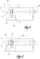
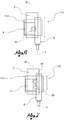
figures 1 to 7 show diagrams of different types of machine tools, provided with a balancing device according to the present invention; -
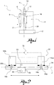
figure 8 shows a diagram of a vertical milling machine fitted with the balancing device according to the present invention; -
figure 9 shows the balancing device according to a preferred embodiment of the present invention. - According to one embodiment variant of the invention (
figure 1 ), a machine tool is a machine with a vertical axis, for example amilling machine 1, comprising abase 2 resting on the foundations, a vertical upright 4 resting on thebase 2 and extending along a vertical axis, and a workinghead 6, supported by the upright 4 and translatable upon command along a movement axis Y. - In addition, the
machine tool 1 comprises aspindle 8 supported by thehead 6, having a working axis Z, preferably translatable upon command along said working axis Z. - The
machine tool 1 comprises drive means 12, suitable for being operated to move thehead 6 along said movement axis Y. - The drive means 12 comprise, according to a preferred embodiment, an
electric motor 14, for example supported by the upright 4 at the top thereof, and a screw-nut system 16 which comprises, for example, a ball bearing screw. - Preferably, (
figures 8 and9 ), the screw-nut system 16 comprises ascrew 18 connected to the motor, positioned along said movement axis Y, and afemale screw 20, for example a cross-head screw, which thescrew 18 engages in; thefemale screw 20 is attached to thehead 6. - The controlled rotation of the screw, imposed by the motor, in one direction of rotation or the other, causes the lowering or raising of the
head 6. - The
machine tool 1 comprises abalancing device 30, preferably supported by thebase 2 connected to thehead 6 and suitable to push saidhead 6 to counter the weight of the head and of the devices supported thereby. The balancing device is extensible, to absorb the movement of thehead 6 along the movement axis Y. - The
balancing device 30 preferably comprises (figures 8 and9 ), acylinder 32 extending along said movement axis Y resting on thebase 2, suitable to be driven hydraulically by means offluid supply ducts 34, for example made in thebase 2. - In addition, the
balancing device 30 comprises apiston 36, engaged so as to sealingly slide in thecylinder 32, extending along said movement axis Y. - The
piston 36 is connected to thecross-member 6. For example, saidbalancing device 30 comprises anattachment flange 38, attached to thecross-member 6 and to thepiston 36. - Preferably, the
screw 18 is aligned with thepiston 36, and in particular thescrew 18 is coaxial to saidpiston 36 and aligned along said movement axis Y. Advantageously, this prevents the formation of tipping or unbalance torques due to the action of the piston and to the reaction of the screw on the cross member. - Preferably, the
piston 36 is internally hollow, so as to receive at least a section of thescrew 18; preferably, moreover, theattachment flange 38 is also crossed by thescrew 18. - Preferably, moreover, the
balancing device 30 comprises adjustment means suitable to allow a slight misalignment of thecylinder axis 32 with the movement axis Y. - For example, said adjustment means comprise a
spherical joint 40 by means of which thecylinder 32 rests on thebase 2. - For example, said
spherical joint 40 comprises asupport flange 42, attached to thebase 2, having a semi-spherical seat, and asupport element 44, attached to the end of thecylinder 32, having a semi-spherical work surface, resting in the semi-spherical seat of thesupport flange 42. - Preferably, the
fluid supply duct 34 crosses thesupport flange 42 and thesupport element 44 to supply the pressurised fluid to the inside of thecylinder 32. - According to one embodiment variant of the present invention, the machine tool is a
gantry machine 50, for example a vertical axis milling machine (figure 2 ). - The
machine 50 comprises twouprights - The
machine 50 comprises across member 54, extending along said horizontal axis J and supported by the twouprights - In addition, the
machine 50 comprises a workinghead 56, supported by the upright 54 and translatable upon command along said horizontal axis J. - The
machine 50 further comprises aspindle 58, supported by thehead 56, having a working axis Z and preferably translatable along said working axis Z. - The
machine 50 is provided with two screw-nut systems cross member 54 along the movement axis Y, distanced along said horizontal axis J. - In addition, the
machine 50 comprises twobalancing devices nut system - Preferably, moreover, the
machine tool 50 comprises a control device to control thebalancing devices - The control device comprises a
control unit 70 suitable to control the twobalancing devices sensor 72 suitable to detect the position of thehead 56 along said horizontal axis J and to transmit a position signal to saidcontrol unit 70 to modulate the activation of thebalancing devices head 56. - According to yet a further embodiment variant of the invention, the machine tool is a
horizontal axis machine 80, for example a horizontal axis boring machine (figure 3 ). - According to a further embodiment variant the machine tool is a machine tool with a mobile upright 90 (
figures 4 and 5 ), for example having a horizontal axis, wherein thebase 2 extends along a longitudinal translation axis X, for example perpendicular to the working axis Z. - The
machine 90 comprises acarriage 92 supported by thebase 2 and translatable upon command along said longitudinal translation axis X, which the upright 4 is supported on. - In said embodiment, the
balancing device 30 is supported by thecarriage 92 and is thus translated together with the upright. - According to yet a further embodiment, a
machine tool 100 provides for two or morebalancing devices 30', 30" engaged with thesame head 6, resting on the same fixed base (variant not shown) or on the translating carriage (figure 5 ). - According to further embodiment variants, a machine tool is a machine tool with a mobile upright 110 (
figures 6 and 7 ), for example having a horizontal axis, wherein thebase 2 extends along a transversal translation axis W, for example parallel to the working axis Z. - The
machine 110 comprises acarriage 112 supported by thebase 2 and translatable upon command along said transversal translation axis W, which the upright 4 is supported on. - In said embodiment, the
balancing device 30 is supported by thecarriage 112 and is thus translated together with the upright 4. - According to yet a further embodiment, a
machine tool 130 provides for two or morebalancing devices 30', 30" engaged with thesame head 6, resting on the same fixed base (variant not shown) or on the translating carriage (figure 7 ). - In the light of the description, the machine tools described above provide for a support structure, for example the
head 6 or thecross member 54, translatable and supported by the upright 4 and bearing aspindle support structure - In addition, the balancing device is supported by a fixed support relative to the support structure it operates on; said fixed support is the
base 2 or thetranslatable carriage - Innovatively, the machine tool according to the present invention makes it possible to balance the weight of the cross member or of the working head and of the components supported thereby, with a system which is particularly efficient and simple to make.
- It is clear that a person skilled in the art may make modifications to the machine tools described above so as to satisfy contingent requirements, all contained within the scope of protection as defined by the following claims.
Claims (9)
- Machine tool (1,50,80,90,100,110,130) comprising a vertical upright (4), a translatable support structure (6,54) supported by the upright (4) and bearing a spindle (8,58) having a working axis (Z), drive means (12) engaged with the support structure (6, 54) to move it upon command along a movement axis (Y) and at least one balancing device (30, 30a, 30b, 30' ,30") extensible along said movement axis (Y) to act so as to push against the support structure and to counter the effect of the weight of said support structure and of the components supported thereby,
wherein the drive means (12) comprise an electric motor (14) and a screw-nut system (16), wherein the screw (18) is connected to the motor (14) and the nut is connected to the support structure (6,54),
wherein the balancing device comprises a cylinder (32), supported by a fixed support relative to the support structure (6, 54) and a piston (36) sealingly slidable in the cylinder (32) and connected to the support structure (6,54), characterised in that the cylinder (32) is a hydraulic cylinder and the screw (18) and the piston (36) extend along said movement axis (Y) and are coaxial with each other. - Machine tool according to claim 1, wherein the screw-nut system is a recirculating ball system.
- Machine tool according to claim 1 or 2, comprising adjustment means suitable to allow a slight misalignment of the cylinder axis (32) with the movement axis (Y).
- Machine tool according to claim 3, wherein the adjustment means comprise a spherical joint (40) by means of which the cylinder (32) rests on the fixed support.
- Machine tool according to any of the previous claims, comprising two uprights (52a, 52b) distanced along a horizontal axis (J), wherein the support structure is a cross-member (54) extending along said horizontal axis (J) and bearing a head (56) translatable upon command along said horizontal axis (J) and in which at least two balancing devices (30a, 30b) are provided, each associated to the respective upright.
- Machine tool according to claim 5, comprising a control device suitable for modulating the action of the balancing devices on the support structure depending on the position of the head (56) along said horizontal axis (J).
- Machine tool according to any of the previous claims, wherein the upright (4) is translatable upon command along a longitudinal (X) or transversal (W) translation axis.
- Machine according to claim 7, comprising a carriage (92, 112) translatable upon command, which the upright (4) is supported on, said balancing device being supported by said carriage (92,112).
- Machine tool according to any of the previous claims, in which two or more balancing devices for each upright are provided, operating on the same support structure.
Applications Claiming Priority (2)
| Application Number | Priority Date | Filing Date | Title |
|---|---|---|---|
| IT000027A ITBS20130027A1 (en) | 2013-03-06 | 2013-03-06 | TOOL MACHINE WITH WORK HEAD BALANCING DEVICE |
| PCT/IB2014/058412 WO2014135994A1 (en) | 2013-03-06 | 2014-01-20 | Machine tool with balancing device of the working head |
Publications (2)
| Publication Number | Publication Date |
|---|---|
| EP2964421A1 EP2964421A1 (en) | 2016-01-13 |
| EP2964421B1 true EP2964421B1 (en) | 2017-06-28 |
Family
ID=48184297
Family Applications (1)
| Application Number | Title | Priority Date | Filing Date |
|---|---|---|---|
| EP14705215.3A Active EP2964421B1 (en) | 2013-03-06 | 2014-01-20 | Machine tool with balancing device of the working head |
Country Status (4)
| Country | Link |
|---|---|
| EP (1) | EP2964421B1 (en) |
| ES (1) | ES2641830T3 (en) |
| IT (1) | ITBS20130027A1 (en) |
| WO (1) | WO2014135994A1 (en) |
Families Citing this family (2)
| Publication number | Priority date | Publication date | Assignee | Title |
|---|---|---|---|---|
| CN104589144A (en) * | 2014-11-27 | 2015-05-06 | 苏州速腾电子科技有限公司 | Cutting machine tool suitable for metal plates with different sizes |
| CN106736832A (en) * | 2017-02-23 | 2017-05-31 | 沈机集团昆明机床股份有限公司 | The balance control system of main spindle box or ram for lathe |
Family Cites Families (5)
| Publication number | Priority date | Publication date | Assignee | Title |
|---|---|---|---|---|
| IT967639B (en) * | 1971-10-15 | 1974-03-11 | Hauser H Ag | EQUIPMENT FOR THE UNIFORMIZATION OF THE LOADS TO WHICH THE SPINDLE OF MACHINES FIXED ON TWO POSTS IS SUBJECT |
| JP3993974B2 (en) * | 2000-09-18 | 2007-10-17 | パスカルエンジニアリング株式会社 | Spindle balancer for machine tools |
| US20090232613A1 (en) * | 2006-03-02 | 2009-09-17 | Pascal Engineering Corporation | Machine Tool Spindle Balancer |
| DE602006006173D1 (en) * | 2006-07-20 | 2009-05-20 | Ross Europa Gmbh | Counterbalancing apparatus |
| JP2010091035A (en) * | 2008-10-09 | 2010-04-22 | Yanagisawa Seiki Mfg Co Ltd | Gas balancer |
-
2013
- 2013-03-06 IT IT000027A patent/ITBS20130027A1/en unknown
-
2014
- 2014-01-20 EP EP14705215.3A patent/EP2964421B1/en active Active
- 2014-01-20 ES ES14705215.3T patent/ES2641830T3/en active Active
- 2014-01-20 WO PCT/IB2014/058412 patent/WO2014135994A1/en not_active Ceased
Non-Patent Citations (1)
| Title |
|---|
| None * |
Also Published As
| Publication number | Publication date |
|---|---|
| EP2964421A1 (en) | 2016-01-13 |
| WO2014135994A1 (en) | 2014-09-12 |
| ES2641830T3 (en) | 2017-11-14 |
| ITBS20130027A1 (en) | 2014-09-07 |
Similar Documents
| Publication | Publication Date | Title |
|---|---|---|
| EP3209457B1 (en) | Machine for processing of volumetric metal objects | |
| US10940548B2 (en) | Machine for machining workpieces | |
| JP2008183666A (en) | Machining center | |
| AU2018368620A1 (en) | Attachment, and handling device comprising an attachment | |
| JP2012152894A (en) | Machining center | |
| KR101732993B1 (en) | Plano miller | |
| EP2412475B1 (en) | Compensation system for a machine tool | |
| WO2014135994A1 (en) | Machine tool with balancing device of the working head | |
| CN100439748C (en) | Balancer Mechanism for Rotary Axis | |
| CN219521167U (en) | Dismounting device for oil pressure damper | |
| CN106312147A (en) | Side milling numerical control planer type milling machine | |
| CN201201148Y (en) | Torque force assembling apparatus | |
| CN114770260B (en) | Wall grinding device and wall grinding robot | |
| CN104959839A (en) | Gantry grinding, polishing and deburring robot workstation | |
| CN204748031U (en) | Polish in longmen, polishing, deburring robot workstation | |
| WO1990006214A1 (en) | An arrangement for bringing the tool-carrying end of a robot beam to a desired one of a plurality of possible, predetermined positions | |
| EP3752320A1 (en) | Improved transfer machine | |
| KR200479140Y1 (en) | Cylinder Head Seat Lapping Apparatus | |
| CN202667707U (en) | Multi-position adjustable vertical drilling machine | |
| RU86514U1 (en) | TABLE MILLING AND ENGRAVING MACHINE | |
| CN201960151U (en) | Improved boring and milling machine | |
| CN208196289U (en) | A kind of drilling and milling machine main shaft telescoping mechanism | |
| JP4805025B2 (en) | Rotary processing machine | |
| CN208197944U (en) | A kind of planar engraving machine | |
| US20180200803A1 (en) | Vertical lathe chuck mounting rack |
Legal Events
| Date | Code | Title | Description |
|---|---|---|---|
| PUAI | Public reference made under article 153(3) epc to a published international application that has entered the european phase |
Free format text: ORIGINAL CODE: 0009012 |
|
| 17P | Request for examination filed |
Effective date: 20150728 |
|
| AK | Designated contracting states |
Kind code of ref document: A1 Designated state(s): AL AT BE BG CH CY CZ DE DK EE ES FI FR GB GR HR HU IE IS IT LI LT LU LV MC MK MT NL NO PL PT RO RS SE SI SK SM TR |
|
| AX | Request for extension of the european patent |
Extension state: BA ME |
|
| DAX | Request for extension of the european patent (deleted) | ||
| GRAP | Despatch of communication of intention to grant a patent |
Free format text: ORIGINAL CODE: EPIDOSNIGR1 |
|
| INTG | Intention to grant announced |
Effective date: 20170201 |
|
| GRAS | Grant fee paid |
Free format text: ORIGINAL CODE: EPIDOSNIGR3 |
|
| GRAA | (expected) grant |
Free format text: ORIGINAL CODE: 0009210 |
|
| AK | Designated contracting states |
Kind code of ref document: B1 Designated state(s): AL AT BE BG CH CY CZ DE DK EE ES FI FR GB GR HR HU IE IS IT LI LT LU LV MC MK MT NL NO PL PT RO RS SE SI SK SM TR |
|
| REG | Reference to a national code |
Ref country code: GB Ref legal event code: FG4D |
|
| REG | Reference to a national code |
Ref country code: CH Ref legal event code: EP |
|
| REG | Reference to a national code |
Ref country code: AT Ref legal event code: REF Ref document number: 904425 Country of ref document: AT Kind code of ref document: T Effective date: 20170715 |
|
| REG | Reference to a national code |
Ref country code: IE Ref legal event code: FG4D |
|
| REG | Reference to a national code |
Ref country code: DE Ref legal event code: R096 Ref document number: 602014011208 Country of ref document: DE |
|
| PG25 | Lapsed in a contracting state [announced via postgrant information from national office to epo] |
Ref country code: GR Free format text: LAPSE BECAUSE OF FAILURE TO SUBMIT A TRANSLATION OF THE DESCRIPTION OR TO PAY THE FEE WITHIN THE PRESCRIBED TIME-LIMIT Effective date: 20170929 Ref country code: NO Free format text: LAPSE BECAUSE OF FAILURE TO SUBMIT A TRANSLATION OF THE DESCRIPTION OR TO PAY THE FEE WITHIN THE PRESCRIBED TIME-LIMIT Effective date: 20170928 Ref country code: FI Free format text: LAPSE BECAUSE OF FAILURE TO SUBMIT A TRANSLATION OF THE DESCRIPTION OR TO PAY THE FEE WITHIN THE PRESCRIBED TIME-LIMIT Effective date: 20170628 Ref country code: HR Free format text: LAPSE BECAUSE OF FAILURE TO SUBMIT A TRANSLATION OF THE DESCRIPTION OR TO PAY THE FEE WITHIN THE PRESCRIBED TIME-LIMIT Effective date: 20170628 Ref country code: LT Free format text: LAPSE BECAUSE OF FAILURE TO SUBMIT A TRANSLATION OF THE DESCRIPTION OR TO PAY THE FEE WITHIN THE PRESCRIBED TIME-LIMIT Effective date: 20170628 |
|
| REG | Reference to a national code |
Ref country code: NL Ref legal event code: MP Effective date: 20170628 |
|
| REG | Reference to a national code |
Ref country code: LT Ref legal event code: MG4D |
|
| REG | Reference to a national code |
Ref country code: ES Ref legal event code: FG2A Ref document number: 2641830 Country of ref document: ES Kind code of ref document: T3 Effective date: 20171114 |
|
| REG | Reference to a national code |
Ref country code: AT Ref legal event code: MK05 Ref document number: 904425 Country of ref document: AT Kind code of ref document: T Effective date: 20170628 |
|
| PG25 | Lapsed in a contracting state [announced via postgrant information from national office to epo] |
Ref country code: SE Free format text: LAPSE BECAUSE OF FAILURE TO SUBMIT A TRANSLATION OF THE DESCRIPTION OR TO PAY THE FEE WITHIN THE PRESCRIBED TIME-LIMIT Effective date: 20170628 Ref country code: RS Free format text: LAPSE BECAUSE OF FAILURE TO SUBMIT A TRANSLATION OF THE DESCRIPTION OR TO PAY THE FEE WITHIN THE PRESCRIBED TIME-LIMIT Effective date: 20170628 Ref country code: NL Free format text: LAPSE BECAUSE OF FAILURE TO SUBMIT A TRANSLATION OF THE DESCRIPTION OR TO PAY THE FEE WITHIN THE PRESCRIBED TIME-LIMIT Effective date: 20170628 Ref country code: BG Free format text: LAPSE BECAUSE OF FAILURE TO SUBMIT A TRANSLATION OF THE DESCRIPTION OR TO PAY THE FEE WITHIN THE PRESCRIBED TIME-LIMIT Effective date: 20170928 Ref country code: LV Free format text: LAPSE BECAUSE OF FAILURE TO SUBMIT A TRANSLATION OF THE DESCRIPTION OR TO PAY THE FEE WITHIN THE PRESCRIBED TIME-LIMIT Effective date: 20170628 |
|
| PG25 | Lapsed in a contracting state [announced via postgrant information from national office to epo] |
Ref country code: RO Free format text: LAPSE BECAUSE OF FAILURE TO SUBMIT A TRANSLATION OF THE DESCRIPTION OR TO PAY THE FEE WITHIN THE PRESCRIBED TIME-LIMIT Effective date: 20170628 Ref country code: AT Free format text: LAPSE BECAUSE OF FAILURE TO SUBMIT A TRANSLATION OF THE DESCRIPTION OR TO PAY THE FEE WITHIN THE PRESCRIBED TIME-LIMIT Effective date: 20170628 Ref country code: SK Free format text: LAPSE BECAUSE OF FAILURE TO SUBMIT A TRANSLATION OF THE DESCRIPTION OR TO PAY THE FEE WITHIN THE PRESCRIBED TIME-LIMIT Effective date: 20170628 Ref country code: EE Free format text: LAPSE BECAUSE OF FAILURE TO SUBMIT A TRANSLATION OF THE DESCRIPTION OR TO PAY THE FEE WITHIN THE PRESCRIBED TIME-LIMIT Effective date: 20170628 |
|
| REG | Reference to a national code |
Ref country code: FR Ref legal event code: PLFP Year of fee payment: 5 |
|
| PG25 | Lapsed in a contracting state [announced via postgrant information from national office to epo] |
Ref country code: PL Free format text: LAPSE BECAUSE OF FAILURE TO SUBMIT A TRANSLATION OF THE DESCRIPTION OR TO PAY THE FEE WITHIN THE PRESCRIBED TIME-LIMIT Effective date: 20170628 Ref country code: IT Free format text: LAPSE BECAUSE OF FAILURE TO SUBMIT A TRANSLATION OF THE DESCRIPTION OR TO PAY THE FEE WITHIN THE PRESCRIBED TIME-LIMIT Effective date: 20170628 Ref country code: IS Free format text: LAPSE BECAUSE OF FAILURE TO SUBMIT A TRANSLATION OF THE DESCRIPTION OR TO PAY THE FEE WITHIN THE PRESCRIBED TIME-LIMIT Effective date: 20171028 Ref country code: SM Free format text: LAPSE BECAUSE OF FAILURE TO SUBMIT A TRANSLATION OF THE DESCRIPTION OR TO PAY THE FEE WITHIN THE PRESCRIBED TIME-LIMIT Effective date: 20170628 |
|
| REG | Reference to a national code |
Ref country code: DE Ref legal event code: R097 Ref document number: 602014011208 Country of ref document: DE |
|
| PG25 | Lapsed in a contracting state [announced via postgrant information from national office to epo] |
Ref country code: DK Free format text: LAPSE BECAUSE OF FAILURE TO SUBMIT A TRANSLATION OF THE DESCRIPTION OR TO PAY THE FEE WITHIN THE PRESCRIBED TIME-LIMIT Effective date: 20170628 |
|
| PLBE | No opposition filed within time limit |
Free format text: ORIGINAL CODE: 0009261 |
|
| STAA | Information on the status of an ep patent application or granted ep patent |
Free format text: STATUS: NO OPPOSITION FILED WITHIN TIME LIMIT |
|
| 26N | No opposition filed |
Effective date: 20180329 |
|
| PG25 | Lapsed in a contracting state [announced via postgrant information from national office to epo] |
Ref country code: SI Free format text: LAPSE BECAUSE OF FAILURE TO SUBMIT A TRANSLATION OF THE DESCRIPTION OR TO PAY THE FEE WITHIN THE PRESCRIBED TIME-LIMIT Effective date: 20170628 |
|
| REG | Reference to a national code |
Ref country code: CH Ref legal event code: PL |
|
| GBPC | Gb: european patent ceased through non-payment of renewal fee |
Effective date: 20180120 |
|
| PG25 | Lapsed in a contracting state [announced via postgrant information from national office to epo] |
Ref country code: LU Free format text: LAPSE BECAUSE OF NON-PAYMENT OF DUE FEES Effective date: 20180120 |
|
| REG | Reference to a national code |
Ref country code: IE Ref legal event code: MM4A |
|
| REG | Reference to a national code |
Ref country code: BE Ref legal event code: MM Effective date: 20180131 |
|
| PG25 | Lapsed in a contracting state [announced via postgrant information from national office to epo] |
Ref country code: LI Free format text: LAPSE BECAUSE OF NON-PAYMENT OF DUE FEES Effective date: 20180131 Ref country code: CH Free format text: LAPSE BECAUSE OF NON-PAYMENT OF DUE FEES Effective date: 20180131 Ref country code: GB Free format text: LAPSE BECAUSE OF NON-PAYMENT OF DUE FEES Effective date: 20180120 Ref country code: BE Free format text: LAPSE BECAUSE OF NON-PAYMENT OF DUE FEES Effective date: 20180131 |
|
| PG25 | Lapsed in a contracting state [announced via postgrant information from national office to epo] |
Ref country code: IE Free format text: LAPSE BECAUSE OF NON-PAYMENT OF DUE FEES Effective date: 20180120 |
|
| PG25 | Lapsed in a contracting state [announced via postgrant information from national office to epo] |
Ref country code: MC Free format text: LAPSE BECAUSE OF FAILURE TO SUBMIT A TRANSLATION OF THE DESCRIPTION OR TO PAY THE FEE WITHIN THE PRESCRIBED TIME-LIMIT Effective date: 20170628 |
|
| PG25 | Lapsed in a contracting state [announced via postgrant information from national office to epo] |
Ref country code: MT Free format text: LAPSE BECAUSE OF NON-PAYMENT OF DUE FEES Effective date: 20180120 |
|
| PG25 | Lapsed in a contracting state [announced via postgrant information from national office to epo] |
Ref country code: TR Free format text: LAPSE BECAUSE OF FAILURE TO SUBMIT A TRANSLATION OF THE DESCRIPTION OR TO PAY THE FEE WITHIN THE PRESCRIBED TIME-LIMIT Effective date: 20170628 |
|
| PG25 | Lapsed in a contracting state [announced via postgrant information from national office to epo] |
Ref country code: PT Free format text: LAPSE BECAUSE OF FAILURE TO SUBMIT A TRANSLATION OF THE DESCRIPTION OR TO PAY THE FEE WITHIN THE PRESCRIBED TIME-LIMIT Effective date: 20170628 |
|
| PG25 | Lapsed in a contracting state [announced via postgrant information from national office to epo] |
Ref country code: CY Free format text: LAPSE BECAUSE OF FAILURE TO SUBMIT A TRANSLATION OF THE DESCRIPTION OR TO PAY THE FEE WITHIN THE PRESCRIBED TIME-LIMIT Effective date: 20170628 Ref country code: HU Free format text: LAPSE BECAUSE OF FAILURE TO SUBMIT A TRANSLATION OF THE DESCRIPTION OR TO PAY THE FEE WITHIN THE PRESCRIBED TIME-LIMIT; INVALID AB INITIO Effective date: 20140120 Ref country code: MK Free format text: LAPSE BECAUSE OF NON-PAYMENT OF DUE FEES Effective date: 20170628 |
|
| PG25 | Lapsed in a contracting state [announced via postgrant information from national office to epo] |
Ref country code: AL Free format text: LAPSE BECAUSE OF FAILURE TO SUBMIT A TRANSLATION OF THE DESCRIPTION OR TO PAY THE FEE WITHIN THE PRESCRIBED TIME-LIMIT Effective date: 20170628 |
|
| P01 | Opt-out of the competence of the unified patent court (upc) registered |
Effective date: 20230526 |
|
| PGFP | Annual fee paid to national office [announced via postgrant information from national office to epo] |
Ref country code: FR Payment date: 20251231 Year of fee payment: 13 |
|
| PGFP | Annual fee paid to national office [announced via postgrant information from national office to epo] |
Ref country code: CZ Payment date: 20251125 Year of fee payment: 13 |
|
| PGFP | Annual fee paid to national office [announced via postgrant information from national office to epo] |
Ref country code: ES Payment date: 20260202 Year of fee payment: 13 |
|
| PGFP | Annual fee paid to national office [announced via postgrant information from national office to epo] |
Ref country code: DE Payment date: 20260123 Year of fee payment: 13 |