EP2964298B1 - Element for inhaling medicinal substances - Google Patents
Element for inhaling medicinal substances Download PDFInfo
- Publication number
- EP2964298B1 EP2964298B1 EP14723508.9A EP14723508A EP2964298B1 EP 2964298 B1 EP2964298 B1 EP 2964298B1 EP 14723508 A EP14723508 A EP 14723508A EP 2964298 B1 EP2964298 B1 EP 2964298B1
- Authority
- EP
- European Patent Office
- Prior art keywords
- inhaler
- conduct
- dispensing device
- substance
- divergent
- Prior art date
- Legal status (The legal status is an assumption and is not a legal conclusion. Google has not performed a legal analysis and makes no representation as to the accuracy of the status listed.)
- Active
Links
- 239000000126 substance Substances 0.000 title claims description 24
- 239000012907 medicinal substance Substances 0.000 claims description 6
- 230000029058 respiratory gaseous exchange Effects 0.000 claims description 6
- 230000000903 blocking effect Effects 0.000 claims description 4
- 210000003928 nasal cavity Anatomy 0.000 claims description 2
- 230000007704 transition Effects 0.000 claims description 2
- 239000002699 waste material Substances 0.000 claims description 2
- 239000003814 drug Substances 0.000 description 15
- 229940079593 drug Drugs 0.000 description 14
- 239000007788 liquid Substances 0.000 description 6
- 230000000241 respiratory effect Effects 0.000 description 6
- 239000000725 suspension Substances 0.000 description 6
- 230000004048 modification Effects 0.000 description 3
- 238000012986 modification Methods 0.000 description 3
- 230000001225 therapeutic effect Effects 0.000 description 3
- 239000003643 water by type Substances 0.000 description 3
- 230000009471 action Effects 0.000 description 2
- 230000008901 benefit Effects 0.000 description 2
- 238000013270 controlled release Methods 0.000 description 2
- 239000012530 fluid Substances 0.000 description 2
- NOESYZHRGYRDHS-UHFFFAOYSA-N insulin Chemical compound N1C(=O)C(NC(=O)C(CCC(N)=O)NC(=O)C(CCC(O)=O)NC(=O)C(C(C)C)NC(=O)C(NC(=O)CN)C(C)CC)CSSCC(C(NC(CO)C(=O)NC(CC(C)C)C(=O)NC(CC=2C=CC(O)=CC=2)C(=O)NC(CCC(N)=O)C(=O)NC(CC(C)C)C(=O)NC(CCC(O)=O)C(=O)NC(CC(N)=O)C(=O)NC(CC=2C=CC(O)=CC=2)C(=O)NC(CSSCC(NC(=O)C(C(C)C)NC(=O)C(CC(C)C)NC(=O)C(CC=2C=CC(O)=CC=2)NC(=O)C(CC(C)C)NC(=O)C(C)NC(=O)C(CCC(O)=O)NC(=O)C(C(C)C)NC(=O)C(CC(C)C)NC(=O)C(CC=2NC=NC=2)NC(=O)C(CO)NC(=O)CNC2=O)C(=O)NCC(=O)NC(CCC(O)=O)C(=O)NC(CCCNC(N)=N)C(=O)NCC(=O)NC(CC=3C=CC=CC=3)C(=O)NC(CC=3C=CC=CC=3)C(=O)NC(CC=3C=CC(O)=CC=3)C(=O)NC(C(C)O)C(=O)N3C(CCC3)C(=O)NC(CCCCN)C(=O)NC(C)C(O)=O)C(=O)NC(CC(N)=O)C(O)=O)=O)NC(=O)C(C(C)CC)NC(=O)C(CO)NC(=O)C(C(C)O)NC(=O)C1CSSCC2NC(=O)C(CC(C)C)NC(=O)C(NC(=O)C(CCC(N)=O)NC(=O)C(CC(N)=O)NC(=O)C(NC(=O)C(N)CC=1C=CC=CC=1)C(C)C)CC1=CN=CN1 NOESYZHRGYRDHS-UHFFFAOYSA-N 0.000 description 2
- 210000004072 lung Anatomy 0.000 description 2
- 210000001331 nose Anatomy 0.000 description 2
- 239000002245 particle Substances 0.000 description 2
- 239000000843 powder Substances 0.000 description 2
- 229960005486 vaccine Drugs 0.000 description 2
- FUFLCEKSBBHCMO-UHFFFAOYSA-N 11-dehydrocorticosterone Natural products O=C1CCC2(C)C3C(=O)CC(C)(C(CC4)C(=O)CO)C4C3CCC2=C1 FUFLCEKSBBHCMO-UHFFFAOYSA-N 0.000 description 1
- MFYSYFVPBJMHGN-ZPOLXVRWSA-N Cortisone Chemical compound O=C1CC[C@]2(C)[C@H]3C(=O)C[C@](C)([C@@](CC4)(O)C(=O)CO)[C@@H]4[C@@H]3CCC2=C1 MFYSYFVPBJMHGN-ZPOLXVRWSA-N 0.000 description 1
- MFYSYFVPBJMHGN-UHFFFAOYSA-N Cortisone Natural products O=C1CCC2(C)C3C(=O)CC(C)(C(CC4)(O)C(=O)CO)C4C3CCC2=C1 MFYSYFVPBJMHGN-UHFFFAOYSA-N 0.000 description 1
- 102000004877 Insulin Human genes 0.000 description 1
- 108090001061 Insulin Proteins 0.000 description 1
- 238000010521 absorption reaction Methods 0.000 description 1
- 230000001154 acute effect Effects 0.000 description 1
- 239000000443 aerosol Substances 0.000 description 1
- 239000003242 anti bacterial agent Substances 0.000 description 1
- 230000002921 anti-spasmodic effect Effects 0.000 description 1
- 229940088710 antibiotic agent Drugs 0.000 description 1
- 208000006673 asthma Diseases 0.000 description 1
- 239000000812 cholinergic antagonist Substances 0.000 description 1
- 230000006835 compression Effects 0.000 description 1
- 238000007906 compression Methods 0.000 description 1
- 229960004544 cortisone Drugs 0.000 description 1
- 239000000850 decongestant Substances 0.000 description 1
- 239000006185 dispersion Substances 0.000 description 1
- 230000000694 effects Effects 0.000 description 1
- 230000008030 elimination Effects 0.000 description 1
- 238000003379 elimination reaction Methods 0.000 description 1
- 239000003172 expectorant agent Substances 0.000 description 1
- 230000003419 expectorant effect Effects 0.000 description 1
- 239000003517 fume Substances 0.000 description 1
- 230000035876 healing Effects 0.000 description 1
- 230000007407 health benefit Effects 0.000 description 1
- 230000004054 inflammatory process Effects 0.000 description 1
- 229910052500 inorganic mineral Inorganic materials 0.000 description 1
- 229940125396 insulin Drugs 0.000 description 1
- 230000010354 integration Effects 0.000 description 1
- 239000000463 material Substances 0.000 description 1
- 238000000034 method Methods 0.000 description 1
- 239000011707 mineral Substances 0.000 description 1
- 239000003595 mist Substances 0.000 description 1
- 210000003097 mucus Anatomy 0.000 description 1
- 210000002850 nasal mucosa Anatomy 0.000 description 1
- 210000003456 pulmonary alveoli Anatomy 0.000 description 1
- 230000007115 recruitment Effects 0.000 description 1
- 230000009467 reduction Effects 0.000 description 1
- 210000002345 respiratory system Anatomy 0.000 description 1
- 150000003839 salts Chemical class 0.000 description 1
- 239000007787 solid Substances 0.000 description 1
- XLYOFNOQVPJJNP-UHFFFAOYSA-N water Substances O XLYOFNOQVPJJNP-UHFFFAOYSA-N 0.000 description 1
Images

Classifications
-
- A—HUMAN NECESSITIES
- A61—MEDICAL OR VETERINARY SCIENCE; HYGIENE
- A61M—DEVICES FOR INTRODUCING MEDIA INTO, OR ONTO, THE BODY; DEVICES FOR TRANSDUCING BODY MEDIA OR FOR TAKING MEDIA FROM THE BODY; DEVICES FOR PRODUCING OR ENDING SLEEP OR STUPOR
- A61M15/00—Inhalators
- A61M15/08—Inhaling devices inserted into the nose
-
- A—HUMAN NECESSITIES
- A61—MEDICAL OR VETERINARY SCIENCE; HYGIENE
- A61M—DEVICES FOR INTRODUCING MEDIA INTO, OR ONTO, THE BODY; DEVICES FOR TRANSDUCING BODY MEDIA OR FOR TAKING MEDIA FROM THE BODY; DEVICES FOR PRODUCING OR ENDING SLEEP OR STUPOR
- A61M11/00—Sprayers or atomisers specially adapted for therapeutic purposes
- A61M11/06—Sprayers or atomisers specially adapted for therapeutic purposes of the injector type
-
- A—HUMAN NECESSITIES
- A61—MEDICAL OR VETERINARY SCIENCE; HYGIENE
- A61M—DEVICES FOR INTRODUCING MEDIA INTO, OR ONTO, THE BODY; DEVICES FOR TRANSDUCING BODY MEDIA OR FOR TAKING MEDIA FROM THE BODY; DEVICES FOR PRODUCING OR ENDING SLEEP OR STUPOR
- A61M15/00—Inhalators
- A61M15/0001—Details of inhalators; Constructional features thereof
- A61M15/0018—Details of inhalators; Constructional features thereof with exhalation check valves
-
- A—HUMAN NECESSITIES
- A61—MEDICAL OR VETERINARY SCIENCE; HYGIENE
- A61M—DEVICES FOR INTRODUCING MEDIA INTO, OR ONTO, THE BODY; DEVICES FOR TRANSDUCING BODY MEDIA OR FOR TAKING MEDIA FROM THE BODY; DEVICES FOR PRODUCING OR ENDING SLEEP OR STUPOR
- A61M15/00—Inhalators
- A61M15/0001—Details of inhalators; Constructional features thereof
- A61M15/0013—Details of inhalators; Constructional features thereof with inhalation check valves
- A61M15/0016—Details of inhalators; Constructional features thereof with inhalation check valves located downstream of the dispenser, i.e. traversed by the product
Landscapes
- Health & Medical Sciences (AREA)
- Engineering & Computer Science (AREA)
- Public Health (AREA)
- Life Sciences & Earth Sciences (AREA)
- Veterinary Medicine (AREA)
- Anesthesiology (AREA)
- Biomedical Technology (AREA)
- Heart & Thoracic Surgery (AREA)
- Hematology (AREA)
- General Health & Medical Sciences (AREA)
- Animal Behavior & Ethology (AREA)
- Bioinformatics & Cheminformatics (AREA)
- Pulmonology (AREA)
- Otolaryngology (AREA)
- Medicinal Preparation (AREA)
- Medicines Containing Material From Animals Or Micro-Organisms (AREA)
Description
- The present invention relates to an elementfo inhaling medicinal and therapeutical substances.
- More specifically, the invention relates to an inhaling element permitting taking medicinal, therapeutial and healing substances inhaling the same directly within respiratory apparatus.
- Inhalation is a technique by which gaseous substances or vapour of volatile substances, or liquid substances or solutions of solid substances finely pulverized are introduced within the respiratory for therapeutical purposes. In fact, inhalations are strongly indicated for treatment of deseases of upper respiratory, usually acute and chronicle inflammatory processes, by thermal waters (particularly solphorous waters and waters rich of mineral salts), or solutions of medicaments with decongestant, antispasmodic and antiessydativa, expectorant and mucus fludificant action. Furthermore, it represent an important novelty to take vaccines, antibiotics, insulin, or similar molecules, only by taking small amounts.
- Known administration or intake of a medicinal substance by the respiratory route can be accomplished in various ways: either by simple inhalation of volatile substances, of fumes released from burning substances or of vapors carrying medicinal substances; or by means of special equipment, also known as inhalers, capable of fragmenting the medicinal preparation into very small particles (mist). In the most common form of inhaler, the medicinal substance emanates for vacuum effect created by a jet of air or of steam passed tangentially to the spout of a capillary tube submerged with the other end within the liquid in which the medicinal substance is dissolved; thereby the liquid is very finely dispersed within the carrier fluid stream.
- Said known inhalers however have the disadvantage of being rather bulky, and clearly not all handsets.
- It is also known that this type of inhaler can cause significant problems, including phenomena of too much instantaneous delivery, misuse, loss of a large amount of drug, which is deposited on the tongue, within the throat, etc., thus reducing their effectiveness.
- Further, disposable portable inhalers are available, allowing one-shot inhalation, for example cortisone to treat asthma, but they consist of immediate supplies that are aggressive for the patient.
- The need to be solved by the solution according to the present invention concerns the possibility of delivering medication through the respiratory tract by means of a device small enough to be inserted into the nostril. Such an administration is advantageous for being able to provide to the body a small amount of drug for long periods, thus improving the absorption and the corresponding health benefit. Document
US2433565 discloses a nose filter containing a foraminous cone wherein a medication may be suspended so that air entering the nose filter and passing to the nostrils will become laden with the vapours of the medication inhalant. Small delivery obtained by the solution according to the invention, allows that the medicinal substance acts maintaining the therapeutically necessary dose, i.e. the right amount that should arrive in a particular district, such as pulmonary alveoli, in order to fully exercise its therapeutic function, thus remaining integrally within the airflow without being absorbed by the body during the run. - Therefore, object of the present invention is to provide an inhaler device that can be used in any situation, without altering the appearance of the person using it and providing the necessary dose for the specific treatment within a time period tha can be set or set in order to obtain a better intake by the body.
further, the object of the present invention is to allow a controlled release of the drug in order not to obstruct normal breathing. - It is an object of the present invention an inhaler element, to be inserted inside a nasal cavity for inhaling medicinal substances, characterized in that it comprises, inside, a dispensing device, said dispensing device providing a convergent conduct for inlet of respiration flow and a divergent conduct for exit of respiration flow, and storage means for the substance to be inhaled, said storage means being provided in flow communication substantially in correspondence of the transition zone between said convergent conduct and said divergent conduct of said dispensing device.
- Particularly, said inhaler element has a substantially frusto-conical shape.
- Preferably according to the invention said storage means for the substance to be inhaled can be comprised of a reservoir containing the substance and in flow communication with said dispensing device by a joint conduct.
- Always according to the invention, said storage means for the substance to be inhaled are comprised of a capillary tube.
- Furthermore, according to the invention, a check valve can be provided at the exit of the divergent conduct of the dispensing device, said valve blocking the flow during the exhalation phase, thus preventing waste of the substance.
- Still according to the invention, terminal portion of conduct with medicinal substance can be realized so as to have an opening for its exit only on the vertical part facing to divergent conduct.
- Furthermore, according to the invention, flow communication conduct between storage means of the substance to be inhaled and dispensing device can provide a valve having a flexible plate and actuated by negative pressure within the throat of convergent conduct.
- Always according to the invention, openings can be provided on the outer surface of the inhaler device.
- Finally, it is an object of the preent invention an inhaler device9. Inhaler device characterized in that it comprises two inhaler elements according to each one of the preceding embodiments and a joint element extending between said two inhaler elements.
- The invention will be now described, for illustrative but not limitative purposes, with particular reference to the drawings of the enclosed figures, wherein:
-
figure 1 shows a schematic side view of an embodiment of the inhaler element according to the invention; -
figure 2 shows a front view of the inhaler element according to the invention; -
figure 3 shows a first embodiment of a dispenser provided in the inhaler element according to the invention; -
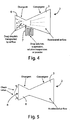
figure 4 shows a second embodiment of a dispenser provided in the inhaler element according to the invention; -
figure 5 shows a first detail of the inhaler element according to the invention; -
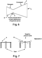
figure 6 shows a second detail of the inhaler element according to the invention; and -
figure 7 shows a third particular of inhaler element according to the invention. - Observing the figures of the accompanying drawings, and initially
figures 1 and 2 , there is shown aninhaler device 1 according to the invention, in the shape of a truncated hollow cone, made of suitable flexible material which ensures the comfort for the patient and better adherence between the device and the nasal mucosa. - A dispenser device, generally indicated by
reference numeral 2, and which will be described in greater detail in the following with reference to the remaining figures, is positioned within theinhaler device 1. The positioning of thedispenser 2 inside the truncated coneshaped inhaler device 1 shown infigures 1 and 2 is merely illustrative, as it can be placed in any position within the same and can be of any size. - Observing now
figure 3 , it is shown in detail adispensing device 2. - Said dispensing
device 2 exploits the difference in air pressure applied by the respiratory act locally to accelerate the speed of the air by means of aconvergent duct 3 of any shape, preferably cylindrical shape, localized at any point within theouter dispensing device 2; in the point of maximum speed within theconvergent duct 3 it occurs, according to Bernoulli law, a reduction of pressure within the flow drawing the drug in the form of solution, suspension, solution/suspension or powder, dragging the same. - The drug is contained within a
tank 4 in fluid communication via aduct 5 with said dispensingdevice 2, in correspondence of the terminal part of said duct convergent 3. - Downstream of the point of maximum speed, the device may incorporate a
divergent conduit 6 of any shape, preferably cylindrical, which will reduce the speed of the air flow and increase the pressure of the same, in such a way as to allow the best integration of the outgoing flow from the device with respiratory airflow. - As already said, in the configuration shown in
figure 3 , the drug, in the form of solution, suspension, solution/suspension or powder to be dispersed within the flow, is contained within areservoir 4 of any shape and size, in which aconduit 5 is inserted that terminates in the throat of theconvergent duct 3; the number ofsuch conduits 5 can be in any number. -
Figure 4 shows a possible modification of thedispensing device 2, that can be adopted in case the drug is available in the form of solution, suspension , solution/suspension. In this case, the liquid containing the drug is contained within acapillary tube 7 of any shape. Thanks to the water capillarity, when the drug is dragged away by the flow, the liquid moves inside the capillary 7, becoming always available to dragging, remaining faced within the throat of theconvergent duct 3; said solution has the advantage of being independent from the vertical tilt. - In a further arrangement shown in
figure 5 mobile parts 8 can be applied at the exit of thedivergent duct 6, allowing the passage of the flow only in the direction towards the lungs, blocking the flow during exhalation, avoiding the dispersion of the drug outwards; thesemovable parts 8 are applied infigure 5 at the end of thedivergent duct 6 but can be applied in any point of thedispensing device 2, be in any number and have any shape adapted to give the properties of blocking reverse flow. - In a further arrangement shown in
figure 6 , the elimination of fogging during the exhalation phase is obtained by a particular configuration of the terminal part of theduct 5 afferent the liquid to be atomized, made so as to show an opening for its exit only in the vertical part facing thedivergent duct 6. - A further arrangement of the
duct 5 is the one shown infigure 7 in which saidconduit 5 incorporates a valve with aflexible plate 9 actuated by the depression within the throat of theconvergent duct 3. - It is also possible that the
inhaler device 1 according to the invention provides openings on its outer surface. - They can also be used two
devices 1, one in each nostril, which may be connected through a suspender cexiting from nostrils. - The
dispenser 2 can also occupy the entire volume within the containment truncated cone coinciding with it. - The inhaler element described in the different previous embodiments, once inserted into one or both nostrils of the user exploits the action of compression of air caused by breathing through the lungs, acting as if they were the engine of a common aerosols device, thus allowing the inhalation of particles of medicinal substances which are delivered by the immission of the flow of moist air coming from outside, so as to allow the micro- slow or controlled release of such substances, up to a maximum of eight hours.
- Furthermore, the inhaler element according to the invention has the advantage of being a disposable and single-dose device of reduced dimensions so that it can be transported without problems and that will not modify the appearance of the user and to divide the taking of the drug in a fixed time or I a time that can be set for the purpose of having a better intake by the body.
- Finally, the device according to the invention also allows the recruitment of vaccines, only possible by means of micro- assumptions as in the present case.
- In the foregoing preferred embodiments have been described the modifications of the present invention have been suggested, but it is to be understood that the those skilled in the art can make modifications and changes without departing from the relevant scope, as defined by the claims attached.
Claims (8)
- Inhaler element (1), to be inserted inside a nasal cavity for inhaling medicinal substances, comprising, inside, a dispensing device (2), said dispensing device (2) providing a convergent conduct (3) for inlet of respiration flow and a divergent conduct (6) for exit of respiration flow, and a reservoir (4) containing the substance to be inhaled and in flow communication with said dispensing device (2) by a joint conduct (5), said reservoir (4) being provided in flow communication substantially in correspondence of the transition zone between said convergent conduct (3) and said divergent conduct (6) of said dispensing device (2).
- Inhaler element (1) according to claim 1, characterized in that it has a substantially frusto-conical shape.
- Inhaler element (1) according to any one of claims 1 - 2, characterized in that said reservoir for the substance to be inhaled is comprised of a capillary tube.
- Inhaler element (1) according to any one of the preceding claims, characterized in that a check valve (8) is provided at the exit of the divergent conduct of the dispensing device (2), said valve (8) blocking the flow during the exhalation phase, thus preventing waste of the substance.
- Inhaler element (1) according to any one of the preceding claims, characterized in that terminal portion of conduct (5; 7) with medicinal substance is realized so as to have an opening for its exit only on the vertical part facing to divergent conduct.
- Inhaler element (1) according to any one of the preceding claims, characterized in that flow communication conduct (5; 7) between reservoir of the substance to be inhaled and dispensing device provides a valve having a flexible plate (9) and actuated by negative pressure within the throat of convergent conduct.
- Inhaler element (1) according to any one of the preceding claims, characterized in that openings are provided on the outer surface of the inhaler device.
- Inhaler device(1) characterized in that it comprises two inhaler elements according to each one of the preceding claims and a joint element extending between said two inhaler element.
Applications Claiming Priority (2)
| Application Number | Priority Date | Filing Date | Title |
|---|---|---|---|
| IT000132A ITRM20130132A1 (en) | 2013-03-06 | 2013-03-06 | INHALER ELEMENT OF MEDICAMENTOUS SUBSTANCES. |
| PCT/IT2014/000067 WO2014136135A1 (en) | 2013-03-06 | 2014-03-06 | Element for inhaling medicinal substances |
Publications (2)
| Publication Number | Publication Date |
|---|---|
| EP2964298A1 EP2964298A1 (en) | 2016-01-13 |
| EP2964298B1 true EP2964298B1 (en) | 2017-10-25 |
Family
ID=48227453
Family Applications (1)
| Application Number | Title | Priority Date | Filing Date |
|---|---|---|---|
| EP14723508.9A Active EP2964298B1 (en) | 2013-03-06 | 2014-03-06 | Element for inhaling medicinal substances |
Country Status (7)
| Country | Link |
|---|---|
| US (1) | US10220168B2 (en) |
| EP (1) | EP2964298B1 (en) |
| CN (1) | CN105307713B (en) |
| CA (1) | CA2940088C (en) |
| HK (1) | HK1220651A1 (en) |
| IT (1) | ITRM20130132A1 (en) |
| WO (1) | WO2014136135A1 (en) |
Families Citing this family (4)
| Publication number | Priority date | Publication date | Assignee | Title |
|---|---|---|---|---|
| US9649468B2 (en) | 2014-09-03 | 2017-05-16 | Fisher & Paykel Healthcare Limited | Respiratory gas humidifier |
| WO2017098386A1 (en) * | 2015-12-11 | 2017-06-15 | Fisher & Paykel Healthcare Limited | Humidification system |
| US10428205B2 (en) * | 2017-08-31 | 2019-10-01 | The Goodyear Tire & Rubber Company | Pneumatic tire |
| WO2023047358A1 (en) * | 2021-09-24 | 2023-03-30 | Bazzica Engineering S.R.L. | Dry powder inhaler |
Family Cites Families (19)
| Publication number | Priority date | Publication date | Assignee | Title |
|---|---|---|---|---|
| US831004A (en) * | 1906-04-04 | 1906-09-11 | Flora E Jousset | Inhaler. |
| US2433565A (en) * | 1946-06-21 | 1947-12-30 | Korman Alexander | Nose filter |
| US3513839A (en) * | 1968-01-02 | 1970-05-26 | Matthew Vacante | Valved nose filter |
| US3747597A (en) * | 1971-11-03 | 1973-07-24 | V Olivera | Nasal filter |
| US4267831A (en) * | 1979-09-24 | 1981-05-19 | Aguilar Rogelio M | Nasal air filter and medicament dispenser device |
| US6478026B1 (en) * | 1999-03-13 | 2002-11-12 | Thomas J. Wood | Nasal ventilation interface |
| DE10105383C2 (en) * | 2001-02-06 | 2003-06-05 | Heptec Gmbh | Anti-snoring device |
| US6679265B2 (en) * | 2001-10-25 | 2004-01-20 | Worldwide Medical Technologies | Nasal cannula |
| GB0215904D0 (en) * | 2002-07-09 | 2002-08-21 | Team Holdings Uk Ltd | Drug delivery system and method |
| US7156098B2 (en) * | 2004-03-19 | 2007-01-02 | Dolezal Creative Innovations, Llc | Breathing air filtration system |
| US7806120B2 (en) * | 2004-12-08 | 2010-10-05 | Ventus Medical, Inc. | Nasal respiratory devices for positive end-expiratory pressure |
| WO2006123323A2 (en) * | 2005-05-17 | 2006-11-23 | Boris Kashmakov | A nose filter |
| US7559327B2 (en) * | 2005-05-31 | 2009-07-14 | Respcare, Inc. | Ventilation interface |
| AU2007258524B2 (en) * | 2006-06-07 | 2012-05-03 | Ventus Medical, Inc. | Layered nasal devices |
| GB0623731D0 (en) * | 2006-11-28 | 2007-01-10 | Optinose As | Delivery device |
| TW200836781A (en) * | 2007-03-07 | 2008-09-16 | Ventus Medical Inc | Nasal devices |
| US20090308398A1 (en) * | 2008-06-16 | 2009-12-17 | Arthur Ferdinand | Adjustable resistance nasal devices |
| US8517022B2 (en) * | 2008-08-19 | 2013-08-27 | Jbr Holding, L.C. | Minimally invasive nasal cannula |
| DK2928531T3 (en) * | 2012-12-04 | 2017-05-22 | Ino Therapeutics Llc | CANNEL FOR MINIMIZING DILUTION DOSAGE DURING NITROGEN OXIDE ADMINISTRATION |
-
2013
- 2013-03-06 IT IT000132A patent/ITRM20130132A1/en unknown
-
2014
- 2014-03-06 US US14/773,001 patent/US10220168B2/en active Active
- 2014-03-06 CA CA2940088A patent/CA2940088C/en active Active
- 2014-03-06 CN CN201480025105.0A patent/CN105307713B/en active Active
- 2014-03-06 EP EP14723508.9A patent/EP2964298B1/en active Active
- 2014-03-06 WO PCT/IT2014/000067 patent/WO2014136135A1/en active Application Filing
-
2016
- 2016-07-23 HK HK16108835.4A patent/HK1220651A1/en unknown
Non-Patent Citations (1)
| Title |
|---|
| None * |
Also Published As
| Publication number | Publication date |
|---|---|
| US10220168B2 (en) | 2019-03-05 |
| ITRM20130132A1 (en) | 2014-09-07 |
| US20160015915A1 (en) | 2016-01-21 |
| CA2940088C (en) | 2021-02-23 |
| EP2964298A1 (en) | 2016-01-13 |
| HK1220651A1 (en) | 2017-05-12 |
| CN105307713A (en) | 2016-02-03 |
| WO2014136135A1 (en) | 2014-09-12 |
| CA2940088A1 (en) | 2014-09-12 |
| CN105307713B (en) | 2019-08-16 |
Similar Documents
| Publication | Publication Date | Title |
|---|---|---|
| EP3316950B1 (en) | Nasal cannula for continuous and simultaneous delivery of aerosolized medicament and high flow therapy | |
| EP2887984B1 (en) | Ventilator aerosol delivery system | |
| US7493898B2 (en) | Inhalation apparatus | |
| US5727542A (en) | General purpose aerosol inhalation apparatus | |
| EP3612262B1 (en) | Dry powder inhaler and spacer device for a dry powder inhaler | |
| EP3144024B1 (en) | Nebulizer mouthpiece for reducing drug loss | |
| EP2964298B1 (en) | Element for inhaling medicinal substances | |
| US20120048271A1 (en) | Solid dosage at patient interface | |
| JP2019520925A (en) | Application of powder aerosol to respiratory control during artificial respiration or respiratory assistance of a patient | |
| CN109045426A (en) | Nebulizer and medical device for nebulae inhalation | |
| CN206715012U (en) | A kind of vaporizer | |
| US10857315B2 (en) | Inhalation device and method for inhaling powders | |
| US20190076612A1 (en) | Nasal inhaler for use with nebulizer system | |
| CN112827042A (en) | Oxygen therapy mask suitable for lung disease treatment | |
| WO1998007464A1 (en) | Valved aerosol inhalation apparatus with reservoir | |
| CN113289172B (en) | Aromatic methoxyflurane inhalation device for treating emergency traumatic pain | |
| CN211751604U (en) | Breathe internal medicine oxygen therapy pipe | |
| CN117717683A (en) | Multifunctional breathing tube without water humidification | |
| MX2013009050A (en) | High impact nebuliser for medical treatments or surgeries by inhalation therapy of upper and lower airway infections or the like. | |
| GB2431883A (en) | Rapid mixing inhaler |
Legal Events
| Date | Code | Title | Description |
|---|---|---|---|
| PUAI | Public reference made under article 153(3) epc to a published international application that has entered the european phase |
Free format text: ORIGINAL CODE: 0009012 |
|
| 17P | Request for examination filed |
Effective date: 20151005 |
|
| AK | Designated contracting states |
Kind code of ref document: A1 Designated state(s): AL AT BE BG CH CY CZ DE DK EE ES FI FR GB GR HR HU IE IS IT LI LT LU LV MC MK MT NL NO PL PT RO RS SE SI SK SM TR |
|
| AX | Request for extension of the european patent |
Extension state: BA ME |
|
| DAX | Request for extension of the european patent (deleted) | ||
| GRAP | Despatch of communication of intention to grant a patent |
Free format text: ORIGINAL CODE: EPIDOSNIGR1 |
|
| INTG | Intention to grant announced |
Effective date: 20170510 |
|
| GRAS | Grant fee paid |
Free format text: ORIGINAL CODE: EPIDOSNIGR3 |
|
| GRAA | (expected) grant |
Free format text: ORIGINAL CODE: 0009210 |
|
| AK | Designated contracting states |
Kind code of ref document: B1 Designated state(s): AL AT BE BG CH CY CZ DE DK EE ES FI FR GB GR HR HU IE IS IT LI LT LU LV MC MK MT NL NO PL PT RO RS SE SI SK SM TR |
|
| REG | Reference to a national code |
Ref country code: GB Ref legal event code: FG4D |
|
| REG | Reference to a national code |
Ref country code: CH Ref legal event code: EP |
|
| REG | Reference to a national code |
Ref country code: AT Ref legal event code: REF Ref document number: 939344 Country of ref document: AT Kind code of ref document: T Effective date: 20171115 |
|
| REG | Reference to a national code |
Ref country code: IE Ref legal event code: FG4D |
|
| REG | Reference to a national code |
Ref country code: DE Ref legal event code: R096 Ref document number: 602014016267 Country of ref document: DE |
|
| REG | Reference to a national code |
Ref country code: NL Ref legal event code: MP Effective date: 20171025 |
|
| REG | Reference to a national code |
Ref country code: LT Ref legal event code: MG4D |
|
| REG | Reference to a national code |
Ref country code: AT Ref legal event code: MK05 Ref document number: 939344 Country of ref document: AT Kind code of ref document: T Effective date: 20171025 |
|
| REG | Reference to a national code |
Ref country code: FR Ref legal event code: PLFP Year of fee payment: 5 |
|
| PG25 | Lapsed in a contracting state [announced via postgrant information from national office to epo] |
Ref country code: NL Free format text: LAPSE BECAUSE OF FAILURE TO SUBMIT A TRANSLATION OF THE DESCRIPTION OR TO PAY THE FEE WITHIN THE PRESCRIBED TIME-LIMIT Effective date: 20171025 |
|
| PG25 | Lapsed in a contracting state [announced via postgrant information from national office to epo] |
Ref country code: FI Free format text: LAPSE BECAUSE OF FAILURE TO SUBMIT A TRANSLATION OF THE DESCRIPTION OR TO PAY THE FEE WITHIN THE PRESCRIBED TIME-LIMIT Effective date: 20171025 Ref country code: LT Free format text: LAPSE BECAUSE OF FAILURE TO SUBMIT A TRANSLATION OF THE DESCRIPTION OR TO PAY THE FEE WITHIN THE PRESCRIBED TIME-LIMIT Effective date: 20171025 Ref country code: NO Free format text: LAPSE BECAUSE OF FAILURE TO SUBMIT A TRANSLATION OF THE DESCRIPTION OR TO PAY THE FEE WITHIN THE PRESCRIBED TIME-LIMIT Effective date: 20180125 Ref country code: SE Free format text: LAPSE BECAUSE OF FAILURE TO SUBMIT A TRANSLATION OF THE DESCRIPTION OR TO PAY THE FEE WITHIN THE PRESCRIBED TIME-LIMIT Effective date: 20171025 Ref country code: ES Free format text: LAPSE BECAUSE OF FAILURE TO SUBMIT A TRANSLATION OF THE DESCRIPTION OR TO PAY THE FEE WITHIN THE PRESCRIBED TIME-LIMIT Effective date: 20171025 |
|
| PG25 | Lapsed in a contracting state [announced via postgrant information from national office to epo] |
Ref country code: RS Free format text: LAPSE BECAUSE OF FAILURE TO SUBMIT A TRANSLATION OF THE DESCRIPTION OR TO PAY THE FEE WITHIN THE PRESCRIBED TIME-LIMIT Effective date: 20171025 Ref country code: HR Free format text: LAPSE BECAUSE OF FAILURE TO SUBMIT A TRANSLATION OF THE DESCRIPTION OR TO PAY THE FEE WITHIN THE PRESCRIBED TIME-LIMIT Effective date: 20171025 Ref country code: IS Free format text: LAPSE BECAUSE OF FAILURE TO SUBMIT A TRANSLATION OF THE DESCRIPTION OR TO PAY THE FEE WITHIN THE PRESCRIBED TIME-LIMIT Effective date: 20180225 Ref country code: AT Free format text: LAPSE BECAUSE OF FAILURE TO SUBMIT A TRANSLATION OF THE DESCRIPTION OR TO PAY THE FEE WITHIN THE PRESCRIBED TIME-LIMIT Effective date: 20171025 Ref country code: GR Free format text: LAPSE BECAUSE OF FAILURE TO SUBMIT A TRANSLATION OF THE DESCRIPTION OR TO PAY THE FEE WITHIN THE PRESCRIBED TIME-LIMIT Effective date: 20180126 Ref country code: BG Free format text: LAPSE BECAUSE OF FAILURE TO SUBMIT A TRANSLATION OF THE DESCRIPTION OR TO PAY THE FEE WITHIN THE PRESCRIBED TIME-LIMIT Effective date: 20180125 Ref country code: LV Free format text: LAPSE BECAUSE OF FAILURE TO SUBMIT A TRANSLATION OF THE DESCRIPTION OR TO PAY THE FEE WITHIN THE PRESCRIBED TIME-LIMIT Effective date: 20171025 |
|
| REG | Reference to a national code |
Ref country code: DE Ref legal event code: R097 Ref document number: 602014016267 Country of ref document: DE |
|
| PG25 | Lapsed in a contracting state [announced via postgrant information from national office to epo] |
Ref country code: CZ Free format text: LAPSE BECAUSE OF FAILURE TO SUBMIT A TRANSLATION OF THE DESCRIPTION OR TO PAY THE FEE WITHIN THE PRESCRIBED TIME-LIMIT Effective date: 20171025 Ref country code: CY Free format text: LAPSE BECAUSE OF FAILURE TO SUBMIT A TRANSLATION OF THE DESCRIPTION OR TO PAY THE FEE WITHIN THE PRESCRIBED TIME-LIMIT Effective date: 20171025 Ref country code: EE Free format text: LAPSE BECAUSE OF FAILURE TO SUBMIT A TRANSLATION OF THE DESCRIPTION OR TO PAY THE FEE WITHIN THE PRESCRIBED TIME-LIMIT Effective date: 20171025 Ref country code: DK Free format text: LAPSE BECAUSE OF FAILURE TO SUBMIT A TRANSLATION OF THE DESCRIPTION OR TO PAY THE FEE WITHIN THE PRESCRIBED TIME-LIMIT Effective date: 20171025 Ref country code: SK Free format text: LAPSE BECAUSE OF FAILURE TO SUBMIT A TRANSLATION OF THE DESCRIPTION OR TO PAY THE FEE WITHIN THE PRESCRIBED TIME-LIMIT Effective date: 20171025 |
|
| PG25 | Lapsed in a contracting state [announced via postgrant information from national office to epo] |
Ref country code: RO Free format text: LAPSE BECAUSE OF FAILURE TO SUBMIT A TRANSLATION OF THE DESCRIPTION OR TO PAY THE FEE WITHIN THE PRESCRIBED TIME-LIMIT Effective date: 20171025 Ref country code: PL Free format text: LAPSE BECAUSE OF FAILURE TO SUBMIT A TRANSLATION OF THE DESCRIPTION OR TO PAY THE FEE WITHIN THE PRESCRIBED TIME-LIMIT Effective date: 20171025 Ref country code: SM Free format text: LAPSE BECAUSE OF FAILURE TO SUBMIT A TRANSLATION OF THE DESCRIPTION OR TO PAY THE FEE WITHIN THE PRESCRIBED TIME-LIMIT Effective date: 20171025 |
|
| PLBE | No opposition filed within time limit |
Free format text: ORIGINAL CODE: 0009261 |
|
| STAA | Information on the status of an ep patent application or granted ep patent |
Free format text: STATUS: NO OPPOSITION FILED WITHIN TIME LIMIT |
|
| 26N | No opposition filed |
Effective date: 20180726 |
|
| PG25 | Lapsed in a contracting state [announced via postgrant information from national office to epo] |
Ref country code: MC Free format text: LAPSE BECAUSE OF FAILURE TO SUBMIT A TRANSLATION OF THE DESCRIPTION OR TO PAY THE FEE WITHIN THE PRESCRIBED TIME-LIMIT Effective date: 20171025 Ref country code: SI Free format text: LAPSE BECAUSE OF FAILURE TO SUBMIT A TRANSLATION OF THE DESCRIPTION OR TO PAY THE FEE WITHIN THE PRESCRIBED TIME-LIMIT Effective date: 20171025 |
|
| REG | Reference to a national code |
Ref country code: BE Ref legal event code: MM Effective date: 20180331 |
|
| PG25 | Lapsed in a contracting state [announced via postgrant information from national office to epo] |
Ref country code: LU Free format text: LAPSE BECAUSE OF NON-PAYMENT OF DUE FEES Effective date: 20180306 |
|
| PG25 | Lapsed in a contracting state [announced via postgrant information from national office to epo] |
Ref country code: BE Free format text: LAPSE BECAUSE OF NON-PAYMENT OF DUE FEES Effective date: 20180331 |
|
| PG25 | Lapsed in a contracting state [announced via postgrant information from national office to epo] |
Ref country code: MT Free format text: LAPSE BECAUSE OF NON-PAYMENT OF DUE FEES Effective date: 20180306 |
|
| PG25 | Lapsed in a contracting state [announced via postgrant information from national office to epo] |
Ref country code: TR Free format text: LAPSE BECAUSE OF FAILURE TO SUBMIT A TRANSLATION OF THE DESCRIPTION OR TO PAY THE FEE WITHIN THE PRESCRIBED TIME-LIMIT Effective date: 20171025 |
|
| PG25 | Lapsed in a contracting state [announced via postgrant information from national office to epo] |
Ref country code: PT Free format text: LAPSE BECAUSE OF FAILURE TO SUBMIT A TRANSLATION OF THE DESCRIPTION OR TO PAY THE FEE WITHIN THE PRESCRIBED TIME-LIMIT Effective date: 20171025 |
|
| PG25 | Lapsed in a contracting state [announced via postgrant information from national office to epo] |
Ref country code: HU Free format text: LAPSE BECAUSE OF FAILURE TO SUBMIT A TRANSLATION OF THE DESCRIPTION OR TO PAY THE FEE WITHIN THE PRESCRIBED TIME-LIMIT; INVALID AB INITIO Effective date: 20140306 Ref country code: MK Free format text: LAPSE BECAUSE OF NON-PAYMENT OF DUE FEES Effective date: 20171025 |
|
| PG25 | Lapsed in a contracting state [announced via postgrant information from national office to epo] |
Ref country code: AL Free format text: LAPSE BECAUSE OF FAILURE TO SUBMIT A TRANSLATION OF THE DESCRIPTION OR TO PAY THE FEE WITHIN THE PRESCRIBED TIME-LIMIT Effective date: 20171025 |
|
| PGFP | Annual fee paid to national office [announced via postgrant information from national office to epo] |
Ref country code: IE Payment date: 20230327 Year of fee payment: 10 Ref country code: FR Payment date: 20230327 Year of fee payment: 10 |
|
| PGFP | Annual fee paid to national office [announced via postgrant information from national office to epo] |
Ref country code: IT Payment date: 20230327 Year of fee payment: 10 Ref country code: GB Payment date: 20230327 Year of fee payment: 10 Ref country code: DE Payment date: 20230328 Year of fee payment: 10 |
|
| P01 | Opt-out of the competence of the unified patent court (upc) registered |
Effective date: 20230517 |
|
| PGFP | Annual fee paid to national office [announced via postgrant information from national office to epo] |
Ref country code: CH Payment date: 20230401 Year of fee payment: 10 |
|
| PGFP | Annual fee paid to national office [announced via postgrant information from national office to epo] |
Ref country code: IE Payment date: 20240326 Year of fee payment: 11 |