EP2964102B1 - Urinsammelvorrichtung - Google Patents
Urinsammelvorrichtung Download PDFInfo
- Publication number
- EP2964102B1 EP2964102B1 EP14717800.8A EP14717800A EP2964102B1 EP 2964102 B1 EP2964102 B1 EP 2964102B1 EP 14717800 A EP14717800 A EP 14717800A EP 2964102 B1 EP2964102 B1 EP 2964102B1
- Authority
- EP
- European Patent Office
- Prior art keywords
- outlet
- base portion
- urine
- flow
- receptacle
- Prior art date
- Legal status (The legal status is an assumption and is not a legal conclusion. Google has not performed a legal analysis and makes no representation as to the accuracy of the status listed.)
- Active
Links
Images



Classifications
-
- A—HUMAN NECESSITIES
- A61—MEDICAL OR VETERINARY SCIENCE; HYGIENE
- A61B—DIAGNOSIS; SURGERY; IDENTIFICATION
- A61B10/00—Instruments for taking body samples for diagnostic purposes; Other methods or instruments for diagnosis, e.g. for vaccination diagnosis, sex determination or ovulation-period determination; Throat striking implements
- A61B10/0045—Devices for taking samples of body liquids
- A61B10/007—Devices for taking samples of body liquids for taking urine samples
Definitions
- This invention relates to a device to assist in the collection of urine from a patient.
- the device is designed to collect initial urine flow, known as a forestream sample.
- Analysis of urine is used as a diagnostic tool for detecting a wide range of conditions and disease.
- the urine can be analysed for particular chemicals that are indicative of infections or whose levels may indicate diseases, including cancer. Different conditions or diseases are detected by analysis of different parts of urine flow.
- the initial flow or forestream may have a higher concentration of bacteria or substances largely resident in the urethra, than the midstream flow. These might include infective organisms of urethritis such as gonococcus or chlamydia, or prostatic secretions.
- the forestream will not be as representative of the general composition of the urine, for example in detecting overall urinary protein or sugar levels, or general urinary tract infections. For these a midstream sample is preferred.
- the patient is typically required to provide a urine sample in a sample bottle.
- Standard sample bottles are relatively small and have a narrow neck, making it difficult for the patient to deliver a sample accurately into the bottle.
- the part of the flow that is not required must also be disposed of, and it can be difficult to do this cleanly, especially for female patients.
- US 7 547 298 shows a device having a funnel for collecting urine, an outlet connected through a valve to a sample bottle, and an overflow outlet.
- Initial flow is directed through the valve into the bottle, from which air leaves through a vent tube.
- the valve provides a further path to the overflow outlet to release a trapped volume. Another small volume is released into the bottle as it is detached.
- This device is efficient at capturing the forestream, but it has a complex construction, due to the valve.
- a simpler construction is shown in WO 2005/107602 .
- This has a funnel with a tube at its base leading to two outlets.
- a sample bottle is attached to the first outlet, while the second is an overflow outlet.
- a flow barrier is placed in the tube at the first outlet, to guide the initial flow preferentially to the bottle, and to allow air to leave the bottle. Once the bottle is full the urine passes to the overflow outlet.
- a valve may seal the forestream sample in the bottle.
- the flow barrier provides a simple construction but its correct operation depends on the flow rate, and it cannot consistently ensure only or all of the forestream is guided to the bottle.
- a urine collection device comprising a collector to collect urine voided by a user, the collector comprising a funnel member, having a funnel wall comprising a substantially frusto-conical top portion, and a base portion, first and second outlets to allow urine to drain from the device, the first outlet being adapted for connection to a receptacle for a urine sample, and the second outlet comprising an overflow outlet, and a diverter device having first and second operative states, such that in a first state the diverter device allows urine to flow through the first outlet to the receptacle for collection of a forestream sample, and in a second state the diverter device prevents flow to the first outlet and allows flow to the overflow outlet, the diverter device being unable to return from the second state to the first state in which the first outlet is provided by the base portion of the funnel member, and the second, overflow outlet is provided in the funnel wall, the diverter device comprises a plug accommodated in the base portion, the plug in the first state
- Providing the diverter device with two operative states means that it will ensure efficient operation, both of collection of the forestream sample and the diversion of the remaining flow to the overflow outlet.
- the diverter device does not return from the second state to the first it does not need to be a valve, and can thus have a simple construction, making the device overall of simple construction.
- the plug provides a particularly simple and effective construction of diverter device. Further, because the lowest part of the second outlet at its junction with the funnel wall is substantially level with the upper end of the plug, this ensures that all the flow which is not collected in the receptacle drains readily from the device.
- the device is designed to be used in a substantially vertical position, and so will be described in that orientation with the terms top, base, upper and lower referring to a vertical orientation.
- the base portion of the funnel member is adapted for connection of the receptacle, so that this is substantially vertical in use.
- the base portion may have means for engaging the external screw thread found at the top of the bottle, designed for attachment of the bottle cap.
- the plug is preferably of an expandable sponge material. It is accommodated in the base portion of the funnel member, which is substantially cylindrical.
- the plug may be an interference fit in the cylindrical base portion.
- the plug is located at its upper end by an abutment in the cylindrical base portion, and at its lower end projects from the cylindrical base portion. The lower end thus projects into the receptacle when this is attached to the device, and leaves a free space at the top of the receptacle when it is removed, to reduce the risk of spillage.
- the second outlet comprises a tube extending from the funnel member substantially at right angles to the cylindrical base portion.
- the inner end of the tube is angled so that at its highest part it projects into the funnel to substantially prevent flow through the second outlet while the plug is in the first state allowing flow to the first outlet.
- the outer end of the tube is shaped to direct the flow away from the receptacle. This helps to ensure that the outside of the receptacle is kept clean and dry.
- the device is conveniently made of plastics material. It has a simple construction, and is easy to use, while collecting a forestream sample in an efficient manner.
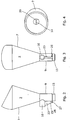
- the urine collection device 1 shown in Figures 1 to 4 is for collection of a forestream sample of urine.
- the device 1 comprises a collector 2 to collect urine voided by a user, and first and second outlets 3, 4 respectively.
- the first outlet 3 is adapted for connection of a receptacle 5 for collection of the sample
- the second outlet 4 is an overflow outlet to deal with the urine flow following the forestream.
- a diverter device 6 is provided to direct the urine flow as required.
- the diverter device 6 has first and second operative states. In a first state the diverter device 6 allows urine to flow through the first outlet 3 to the receptacle 5 for collection of the forestream sample, and in a second state the diverter device 6 prevents flow to the first outlet 3 and allows flow to the second overflow outlet 4. The diverter device 6 cannot return to the first state from the second state.
- the device 1 will be described in the vertical orientation shown, as it is the normal position of use. Terms such as top, base, upper and lower should be construed accordingly.
- the collector 2 comprises a funnel member 7 having a wall with a wider top portion 8 of substantially frusto-conical shape, narrowing to a substantially cylindrical base portion 9.
- the top 8 is angled and shaped for ease of use.
- the outer surface has indentations 10 to indicate to the user how the device 1 is to be held. There is a single indentation 10 at the rear of the device 1 for the thumb, and three at the front for the fingers.
- the first and second outlets 3, 4 are provided in the base portion 9 which has an open lower end 11.
- the first outlet is at the lower end 11 of the base portion 9.
- the receptacle 5 is connected to the lower end 11 so that it is vertical in use.
- the receptacle 5 is a standard sample bottle, and the manner of connection will be described below.
- the diverter device 6 comprises an expandable plug 12 of sponge material.
- the plug 12 is substantially cylindrical and is an interference fit in the base portion 9.
- the sponge material is chosen so that in its first, dry state it allows urine to pass through it.
- the material expands on contact with liquid and so gradually moves into its second state, in which it prevents further urine flow through it. It will be appreciated that the plug cannot return from the second state to the first state.
- the position of the plug 12 in the base portion 9 is defined by abutment of its top surface 13 with a rail 14 (best seen in Figure 4 ) which extends transversely across the base portion 9.
- the lower end 15 of the plug 12 projects below the lower end 11 of the base portion 9 and into the receptacle 5.
- the second outlet 4 comprises a tube 16 extending substantially at right angles to the base portion 9, so approximately horizontally in use.
- the tube 16 projects from the funnel wall above the first outlet 3.
- the lowest point 17 of the tube 16 at its junction with the funnel wall is level with the top of the rail 14, so that it is just above the top surface 13 of the plug 12. This assists in ensuring that urine drains easily and fully from the device 1, as there will be no trapped volume of urine on completion of urination.
- the inner end 18 of the tube 16 is angled, so that its top surface 19 projects slightly into the funnel member 7. This forms a guide surface 20 directing urine flow from the top of the funnel member 7 away from the overflow outlet 4.
- the outer end 21 of the tube 16 projects from the funnel member 7 so that urine leaving the device 1 through the overflow outlet 4 is directed away from the receptacle 5.
- the outer edge 22 is also shaped with a lip to ensure that the overflow urine leaves in a stream rather than dribbling back towards the funnel member 7.
- the base portion 9 is formed with a lug 23 extending downwardly from the lowest point 17 of the tube 16 to project slightly beyond the lower end 11 of the base portion 9. It is best seen in Figures 1 and 3 .
- the lug 23 provides rigidity for the device 1, and also the connection means 24 for the receptacle 5.
- the lug 23 has an upwardly-extending rebate 26 and an inwardly-extending projection 27, with which an external screw thread 28 on the receptacle 5 engages to attach the receptacle 5 to the device 1.
- the upper end 29 of the receptacle 5 engages the lower end 11 of the base portion 9.
- the device is preferably injection-moulded in a suitable plastics material. It is simple to assemble, as the plug 12 is put in position in the base portion 9. The assembled device 1 (without the receptacle 5) will be packed in suitable protective packaging (not shown) to prevent contamination.
- the device 1 is removed from its packaging.
- a sterilised sample bottle has its top (not shown) removed, and the bottle is then screwed onto the base portion 9 to act as the receptacle 5.
- the user then urinates into the top portion 8 of the funnel member 7.
- the guide surface 20 ensures that the initial urine flow passes to the first outlet 3, through the plug 12 (which is in its first state) and into the receptacle 5.
- the plug 12 expands on contact with the urine and assumes its second state, in which further flow through the first outlet 3 is prevented.
- Urine flow is then directed to the second outlet 4 until urination is completed.
- the urine drains fully from the device 1 through the second outlet 4.
- the receptacle 5 can then be unscrewed, leaving the plug 12 in the device 1, so that there is a free space at the top of the receptacle 5. This reduces the risk of spillage on removal of the receptacle 5.
- the receptacle 5 containing the forestream sample can then be recapped.
- the forestream sample is taken efficiently, with very little or no mess, as the overflow outlet 4 directs the unwanted urine away from the receptacle 5.
- the only urine remaining in the device 1 is in the plug 12, whose material is chosen so that it does not drip.
- Figures 5 to 8 show a modification of the urine collection device of Figures 1 to 4 , and corresponding reference numerals have been applied to corresponding parts. The embodiment of Figures 5 to 8 does not fall within the scope of the claims.
- the top portion 8 of the funnel member 7 is the same as that of Figures 1 to 4 , but the base portion 9 is modified.
- the first outlet 3 is provided in the funnel wall above the second, overflow outlet 4.
- the diverter device 6 comprises a membrane 30 extending across the base portion 9 between the two outlets 3, 4. In a first state the membrane 30 prevents flow to the second outlet 4, guiding it to the first outlet 3. When wetted, the membrane 30 breaks, assuming its second state in which it allows flow to the second outlet 4. Clearly, the membrane cannot return from the second state to the first state.
- the first outlet 3 comprises a tube 31 extending from the base portion 9 in a direction angled slightly down from the horizontal.
- the receptacle 5 receives the outer end 32 of the tube 31 in a sealing manner.
- the second outlet 4 is formed by the open lower end 11 of the base portion 9, and is of angled outline. It has a vertical portion 33 in line with the funnel member 7, leading to an angled end portion 34.
- the end portion 34 is substantially parallel to the tube 31, but is slightly longer.
- a projection 35 is provided on the outside of the end portion 34, adjacent to the tube 31. The external screw thread on the receptacle 5 engages with the projection 35 to attach the receptacle 5 to the device 1.
- the membrane 30 is accommodated at the top of the vertical portion 33 of the overflow outlet 4, substantially in line with the lowest point 36 of the tube 31. It may be attached by adhesive or welding, and will be of any suitable sheet plastics or paper material.
- the device 1 is of any suitable plastics material, and is packaged without the receptacle 5.
- the device 1 For use, it is removed from the packaging and the receptacle 5 attached.
- the initial urine flow is guided by the membrane 30 through the first outlet 3 to the receptacle 5.
- the flow wets the membrane 30, which breaks, so that subsequent flow passes through the overflow outlet 4.
- the device 1 can be turned so that the receptacle 5 is closer to the vertical before it is unscrewed from the device 1. Because the sample was collected with the receptacle 5 closer to the horizontal, when it is turned there will be free space at the top of the receptacle 5 to reduce the risk of spillage.
- the receptacle 5 can then be re-capped and the device disposed of.
- the device 1 ensures that a forestream sample is taken efficiently and cleanly, because the urine drains fully from the device 1.
- the receptacle 5 In a modification it would be possible for the receptacle 5 to be attached by a push fit onto the first outlet 3 rather than by the screw thread.
Landscapes
- Health & Medical Sciences (AREA)
- Life Sciences & Earth Sciences (AREA)
- Molecular Biology (AREA)
- Surgery (AREA)
- Engineering & Computer Science (AREA)
- Biomedical Technology (AREA)
- Heart & Thoracic Surgery (AREA)
- Medical Informatics (AREA)
- Hematology (AREA)
- Pathology (AREA)
- Animal Behavior & Ethology (AREA)
- General Health & Medical Sciences (AREA)
- Public Health (AREA)
- Veterinary Medicine (AREA)
- Sampling And Sample Adjustment (AREA)
- Investigating Or Analysing Biological Materials (AREA)
Claims (9)
- Urinsammelvorrichtung (1), umfassend einen Sammler (2) zum Sammeln von Urin, der von einem Benutzer ausgeschieden wird, wobei der Sammler (2) ein Trichterglied (7) mit einer Trichterwand, die einen im Wesentlichen kegelstumpfförmigen oberen Abschnitt (8) und einen Basisabschnitt (9) umfasst, einen ersten und einen zweiten Auslass (3, 4), damit Urin von der Vorrichtung ablaufen kann, wobei der erste Auslass (3) für eine Urinprobe zur Verbindung mit einer Aufnahme (5) ausgeführt ist, und der zweite Auslass (4) einen Überlaufauslass umfasst, und eine Umlenkvorrichtung (6) mit einem ersten und einem zweiten Betriebszustand umfasst, so dass die Umlenkvorrichtung (6) in einem ersten Zustand gestattet, dass Urin zum Sammeln einer Initialstrahlprobe durch den ersten Auslass (3) zu der Aufnahme (5) strömt, und die Umlenkvorrichtung (6) in einem zweiten Zustand eine Strömung zu dem ersten Auslass (3) verhindert und eine Strömung zu dem Überflussauslass gestattet, wobei die Umlenkvorrichtung (6) nicht aus dem zweiten Zustand in den ersten Zustand zurückkehren kann, dadurch gekennzeichnet, dass der erste Auslass (3) durch den Basisabschnitt (9) des Trichterglieds (7) bereitgestellt ist und der zweite Auslass - der Überflussauslass (4) - in der Trichterwand vorgesehen ist, die Umlenkvorrichtung (6) einen in dem Basisabschnitt (9) aufgenommenen Stopfen (12) umfasst, wobei der Stopfen (12) im ersten Zustand eine Strömung zu dem ersten Auslass (3) gestattet und bei Kontakt mit Flüssigkeit in den zweiten Zustand expandiert, um eine weitere Strömung zu dem ersten Auslass (3) zu verhindern und eine Strömung zu dem Überflussauslass (4) zu gestatten, und der unterste Teil des Überflussauslasses (4) an seinem Übergang zu der Trichterwand im Wesentlichen auf derselben Höhe wie das obere Ende des Stopfens (12) liegt.
- Urinsammeivorrichtung nach Anspruch 1, wobei der Basisabschnitt (9) des Trichterglieds (7) zur Verbindung der Aufnahme (5) ausgeführt ist.
- Urinsammelvorrichtung nach Anspruch 1 oder Anspruch 2, wobei der Basisabschnitt (9) Mittel zur Ineingriffnahme eines äußeren Schraubengewindes am oberen Teil der Aufnahme (5) aufweist.
- Urinsammelvorrichtung nach einem der vorhergehenden Ansprüche, wobei der Stopfen (12) aus einem expandierbaren Schwammmaterial ist.
- Urinsammelvorrichtung nach einem der vorhergehenden Ansprüche, wobei der Stopfen (12) im Basisabschnitt (9), der im Wesentlichen zylindrisch ist, aufgenommen ist.
- Urinsammelvorrichtung nach Anspruch 5, wobei der Stopfen (12) an seinem oberen Ende durch einen Anschlag in dem zylindrischen Basisabschnitt (9) lokalisiert ist und an seinem unteren Ende von dem zylindrischen Basisabschnitt (9) vorragt.
- Urinsammelvorrichtung nach einem der vorhergehenden Ansprüche, wobei der zweite Auslass (4) eine Röhre (16) umfasst, die sich von dem Trichterglied (7) im Wesentlichen rechtwinklig zu dem zylindrischen Basisabschnitt (9) erstreckt.
- Urinsammelvorrichtung nach Anspruch 7, wobei das innere Ende der Röhre (16) abgewinkelt ist, so dass sie an ihrem höchsten Teil in das Trichterglied (7) hineinragt, um ein Strömen durch den zweiten Auslass (4) im Wesentlichen zu verhindern, während die Umlenkvorrichtung (6) in dem ersten Zustand ist, in dem ein Strömen zu dem ersten Auslass (3) gestattet ist.
- Urinsammelvorrichtung nach Anspruch 7 oder Anspruch 8, wobei das äußere Ende der Röhre (16) so gestaltet ist, dass die Strömung von der Aufnahme (5) weg gelenkt wird.
Priority Applications (1)
| Application Number | Priority Date | Filing Date | Title |
|---|---|---|---|
| EP20171033.2A EP3701879A1 (de) | 2013-03-04 | 2014-03-04 | Urinsammelvorrichtung |
Applications Claiming Priority (2)
| Application Number | Priority Date | Filing Date | Title |
|---|---|---|---|
| GBGB1303799.9A GB201303799D0 (en) | 2013-03-04 | 2013-03-04 | Urine collection device |
| PCT/GB2014/050630 WO2014135856A1 (en) | 2013-03-04 | 2014-03-04 | Urine collection device |
Related Child Applications (1)
| Application Number | Title | Priority Date | Filing Date |
|---|---|---|---|
| EP20171033.2A Division EP3701879A1 (de) | 2013-03-04 | 2014-03-04 | Urinsammelvorrichtung |
Publications (2)
| Publication Number | Publication Date |
|---|---|
| EP2964102A1 EP2964102A1 (de) | 2016-01-13 |
| EP2964102B1 true EP2964102B1 (de) | 2020-04-29 |
Family
ID=48142349
Family Applications (2)
| Application Number | Title | Priority Date | Filing Date |
|---|---|---|---|
| EP20171033.2A Withdrawn EP3701879A1 (de) | 2013-03-04 | 2014-03-04 | Urinsammelvorrichtung |
| EP14717800.8A Active EP2964102B1 (de) | 2013-03-04 | 2014-03-04 | Urinsammelvorrichtung |
Family Applications Before (1)
| Application Number | Title | Priority Date | Filing Date |
|---|---|---|---|
| EP20171033.2A Withdrawn EP3701879A1 (de) | 2013-03-04 | 2014-03-04 | Urinsammelvorrichtung |
Country Status (7)
| Country | Link |
|---|---|
| US (2) | US11197659B2 (de) |
| EP (2) | EP3701879A1 (de) |
| JP (1) | JP6437926B2 (de) |
| CN (2) | CN109009237A (de) |
| ES (1) | ES2806695T3 (de) |
| GB (1) | GB201303799D0 (de) |
| WO (1) | WO2014135856A1 (de) |
Families Citing this family (22)
| Publication number | Priority date | Publication date | Assignee | Title |
|---|---|---|---|---|
| WO2017023794A1 (en) * | 2015-07-31 | 2017-02-09 | Medivance Incorporated | Urine output collection and monitoring system |
| CN107898477A (zh) * | 2017-10-16 | 2018-04-13 | 宁夏医科大学总医院 | 可定向稳流的尿液样本采用容器 |
| CN107981891A (zh) * | 2017-12-27 | 2018-05-04 | 上海云霓商务咨询有限公司 | 尿液收集器 |
| EP4252816A3 (de) | 2018-05-22 | 2024-01-17 | C. R. Bard, Inc. | Katheterisierungssystem und anwendungsverfahren dafür |
| JP7326348B2 (ja) * | 2018-06-01 | 2023-08-15 | クリアトラック テクノロジーズ,エルエルシー | 尿流量計 |
| WO2020033752A1 (en) | 2018-08-10 | 2020-02-13 | C. R. Bard, Inc. | Automated urine-output-measurement systems and methods thereof |
| CN109350131A (zh) * | 2018-12-04 | 2019-02-19 | 大连科万维医疗科技有限公司 | 一种中段尿样收集器 |
| CN110068664B (zh) * | 2019-05-28 | 2024-05-28 | 菏泽学院 | 一种bod5测量水样试剂瓶 |
| MX2022004214A (es) | 2019-10-07 | 2022-09-23 | Novosanis Nv | Muestreador de líquidos de volúmenes pequeños. |
| GB2604824B (en) | 2019-11-27 | 2024-08-21 | Honorix Ltd | Disposable urine collection container |
| US12083261B2 (en) | 2020-06-05 | 2024-09-10 | C. R. Bard, Inc. | Automated fluid output monitoring |
| US11703365B2 (en) | 2020-07-14 | 2023-07-18 | C. R. Bard, Inc. | Automatic fluid flow system with push-button connection |
| US12055249B2 (en) | 2020-07-21 | 2024-08-06 | C. R. Bard, Inc. | Automatic fluid flow system with retractable connection |
| WO2022108589A1 (en) | 2020-11-19 | 2022-05-27 | C.R. Bard, Inc. | Dynamic pressure response system |
| US12408853B2 (en) | 2020-12-17 | 2025-09-09 | C. R. Bard, Inc. | Smart bag to measure urine output via catheter |
| US12364423B2 (en) | 2020-12-21 | 2025-07-22 | C. R. Bard, Inc. | Automated urinary output-measuring systems and methods |
| US11931151B2 (en) | 2020-12-22 | 2024-03-19 | C. R. Bard, Inc. | Automated urinary output measuring system |
| US12246146B2 (en) | 2020-12-23 | 2025-03-11 | C. R. Bard, Inc. | Automated weight based fluid output monitoring system |
| EP4297649A1 (de) | 2021-02-23 | 2024-01-03 | C. R. Bard, Inc. | Selbstlernende und nichtinvasive blasenüberwachungssysteme und -verfahren |
| US12446813B2 (en) | 2021-08-23 | 2025-10-21 | C. R. Bard, Inc. | Automated urine output system for attachment to hospital bed |
| GB2621386A (en) * | 2022-08-11 | 2024-02-14 | Owen Mumford Ltd | Apparatus for facilitating forestream collection of urine |
| CN116158790B (zh) * | 2023-04-13 | 2025-09-12 | 中国人民解放军总医院第六医学中心 | 一种移动体检取样装置 |
Family Cites Families (35)
| Publication number | Priority date | Publication date | Assignee | Title |
|---|---|---|---|---|
| US2850050A (en) * | 1955-07-08 | 1958-09-02 | Frank X Connolly | Liquid specimen collecting device |
| US3161891A (en) * | 1963-12-12 | 1964-12-22 | Ralph M Bauman | Portable urine specimen collecting device |
| US3177500A (en) * | 1964-08-06 | 1965-04-13 | Ralph M Bauman | Portable urine specimen collecting device |
| US3750648A (en) * | 1971-01-22 | 1973-08-07 | D Gleason | Means for collecting specimens of urine |
| US3943770A (en) * | 1974-11-06 | 1976-03-16 | Mcdonald Bernard | Midstream urine specimen collection device |
| US3982898A (en) | 1976-01-08 | 1976-09-28 | Mcdonald Bernard | Apparatus for collecting urine sample |
| US4106490A (en) | 1976-09-27 | 1978-08-15 | Raymond Spilman | Urine collection aid |
| AR222162A1 (es) * | 1977-12-01 | 1981-04-30 | Pietersen Anthonius H | Un material avisador de incendios |
| US4276889A (en) * | 1979-04-19 | 1981-07-07 | Shs Enterprises, Ltd. | Urine specimen collecting device |
| US4331162A (en) * | 1979-04-19 | 1982-05-25 | Shs Enterprises, Ltd. | Urine specimen collecting device and method of use |
| US4492258A (en) | 1983-02-18 | 1985-01-08 | Whitman Medical Corporation | Sterile urine specimen collection |
| US4494581A (en) * | 1983-02-18 | 1985-01-22 | Whitman Medical Corporation | Isolation of forestream and midstream portions of collected urine samples |
| GB8431388D0 (en) | 1984-12-12 | 1985-01-23 | Univ Manchester | Liquid sampling device |
| US4769215A (en) | 1987-03-24 | 1988-09-06 | Franklin Diagnostics, Inc. | Integrity preserving and determining urine sample collection apparatus |
| US4891993A (en) | 1988-09-30 | 1990-01-09 | Prevention Sciences Incorporated | Apparatus and method for measurement of urine void volumes |
| GB8829203D0 (en) | 1988-12-14 | 1989-01-25 | Intelbrit Technologies | Urine sampling device |
| ZA903244B (en) * | 1989-04-28 | 1991-03-27 | Uroshield Pty Limited | Mid stream urine device |
| GB2247626A (en) | 1990-09-05 | 1992-03-11 | Squibb & Sons Inc | Urine sampling device |
| US5766136A (en) * | 1995-03-08 | 1998-06-16 | Cawood; Charles David | Midstream urine collector with deflection shield |
| CA2170936C (en) * | 1995-03-08 | 2002-05-28 | Charles David Cawood | Flushable midstream urine collector |
| US5711310A (en) | 1996-07-19 | 1998-01-27 | Vinayagamoorthy; Thuraiayah | Apparatus for collecting a mid-stream urine sample |
| US6168758B1 (en) | 1997-11-19 | 2001-01-02 | Starplex Scientific | Liquid sample assay device |
| ATE448760T1 (de) | 2000-03-30 | 2009-12-15 | Orde Levinson | Urintrichter |
| WO2003070131A1 (en) | 2002-02-20 | 2003-08-28 | Orde Levinson | A urine sample collection device |
| GB0217390D0 (en) | 2002-07-26 | 2002-09-04 | Lee Helen | Liquid sampler and method |
| US7172559B2 (en) | 2003-06-28 | 2007-02-06 | Yong Peter A K | Dual-chamber liquid receiving and containing device |
| MY142781A (en) * | 2003-06-28 | 2010-12-31 | Peter A K Yong | Dual-chamber liquid receiving and containing device |
| CN100464691C (zh) * | 2003-06-28 | 2009-03-04 | 彼得·A·K·勇 | 双腔室液体接收和容纳装置 |
| GB0410142D0 (en) | 2004-05-07 | 2004-06-09 | Cunningham Robert W | Urine collection device |
| US20060064034A1 (en) | 2004-09-23 | 2006-03-23 | Stewart David M | Midstream urination collection device |
| GB2440842B (en) * | 2006-09-30 | 2008-08-20 | Funnelly Enough Ltd | Urine collection device |
| US7833169B2 (en) * | 2007-01-29 | 2010-11-16 | Hollister Incorporated | Device and method for the collection of a urine sample |
| CA2668792C (en) * | 2008-06-30 | 2017-08-01 | Tyco Healthcare Group Lp | Valve assembly including a dissolvable valve member |
| GB0821057D0 (en) * | 2008-11-18 | 2008-12-24 | Knight Scient Ltd | Device for collecting first pass urine |
| JP6165624B2 (ja) | 2010-03-25 | 2017-07-19 | デピュー シンセス プロダクツ, インコーポレーテッドDePuy Synthes Products, Inc. | 医療用使い捨て画像装置を提供するためのシステムおよび方法 |
-
2013
- 2013-03-04 GB GBGB1303799.9A patent/GB201303799D0/en not_active Ceased
-
2014
- 2014-03-04 WO PCT/GB2014/050630 patent/WO2014135856A1/en not_active Ceased
- 2014-03-04 EP EP20171033.2A patent/EP3701879A1/de not_active Withdrawn
- 2014-03-04 EP EP14717800.8A patent/EP2964102B1/de active Active
- 2014-03-04 JP JP2015560765A patent/JP6437926B2/ja not_active Expired - Fee Related
- 2014-03-04 CN CN201810899738.4A patent/CN109009237A/zh active Pending
- 2014-03-04 US US14/772,451 patent/US11197659B2/en active Active
- 2014-03-04 CN CN201480022382.6A patent/CN105142531B/zh active Active
- 2014-03-04 ES ES14717800T patent/ES2806695T3/es active Active
-
2021
- 2021-11-22 US US17/532,379 patent/US20220079567A1/en not_active Abandoned
Non-Patent Citations (1)
| Title |
|---|
| None * |
Also Published As
| Publication number | Publication date |
|---|---|
| US20160022249A1 (en) | 2016-01-28 |
| CN109009237A (zh) | 2018-12-18 |
| US11197659B2 (en) | 2021-12-14 |
| US20220079567A1 (en) | 2022-03-17 |
| ES2806695T3 (es) | 2021-02-18 |
| JP6437926B2 (ja) | 2018-12-12 |
| GB201303799D0 (en) | 2013-04-17 |
| EP2964102A1 (de) | 2016-01-13 |
| CN105142531A (zh) | 2015-12-09 |
| JP2016514261A (ja) | 2016-05-19 |
| CN105142531B (zh) | 2018-09-04 |
| WO2014135856A1 (en) | 2014-09-12 |
| EP3701879A1 (de) | 2020-09-02 |
Similar Documents
| Publication | Publication Date | Title |
|---|---|---|
| US20220079567A1 (en) | Urine collection device | |
| US20240341736A1 (en) | Urine-specimen collection, storage, and testing device | |
| EP2068717B1 (de) | Urinsammelvorrichtung | |
| US20180103934A1 (en) | Urine-specimen collection, storage and testing device | |
| CN101331398B (zh) | 粪便采集容器 | |
| US6537262B2 (en) | Female urine collector | |
| JP2017516980A (ja) | 流体採集デバイス | |
| CN104185459A (zh) | 女性排尿接纳器 | |
| US7214199B1 (en) | Urine analysis collection kit for veterinary use | |
| US20060064034A1 (en) | Midstream urination collection device | |
| CN206696039U (zh) | 一种尿液采集装置 | |
| RU2363384C2 (ru) | Устройство для взятия пробы крови, в частности, у новорожденных и младенцев или маленьких животных | |
| CN107149488A (zh) | 一种尿液采集装置 | |
| CN205449532U (zh) | 一种粪便及尿液一体式检验取样装置 | |
| GB2442282A (en) | Midstream urine sample collector | |
| JP2024007715A (ja) | 採取装置、及び採取方法 | |
| HK1133565B (en) | Urine collection device | |
| GB2594976A (en) | Test device |
Legal Events
| Date | Code | Title | Description |
|---|---|---|---|
| PUAI | Public reference made under article 153(3) epc to a published international application that has entered the european phase |
Free format text: ORIGINAL CODE: 0009012 |
|
| 17P | Request for examination filed |
Effective date: 20150929 |
|
| AK | Designated contracting states |
Kind code of ref document: A1 Designated state(s): AL AT BE BG CH CY CZ DE DK EE ES FI FR GB GR HR HU IE IS IT LI LT LU LV MC MK MT NL NO PL PT RO RS SE SI SK SM TR |
|
| AX | Request for extension of the european patent |
Extension state: BA ME |
|
| DAX | Request for extension of the european patent (deleted) | ||
| STAA | Information on the status of an ep patent application or granted ep patent |
Free format text: STATUS: EXAMINATION IS IN PROGRESS |
|
| 17Q | First examination report despatched |
Effective date: 20170301 |
|
| GRAP | Despatch of communication of intention to grant a patent |
Free format text: ORIGINAL CODE: EPIDOSNIGR1 |
|
| STAA | Information on the status of an ep patent application or granted ep patent |
Free format text: STATUS: GRANT OF PATENT IS INTENDED |
|
| INTG | Intention to grant announced |
Effective date: 20171212 |
|
| RIN1 | Information on inventor provided before grant (corrected) |
Inventor name: FORTE, GIOVANNA FILOMENA LINA |
|
| GRAJ | Information related to disapproval of communication of intention to grant by the applicant or resumption of examination proceedings by the epo deleted |
Free format text: ORIGINAL CODE: EPIDOSDIGR1 |
|
| STAA | Information on the status of an ep patent application or granted ep patent |
Free format text: STATUS: EXAMINATION IS IN PROGRESS |
|
| INTC | Intention to grant announced (deleted) | ||
| GRAP | Despatch of communication of intention to grant a patent |
Free format text: ORIGINAL CODE: EPIDOSNIGR1 |
|
| STAA | Information on the status of an ep patent application or granted ep patent |
Free format text: STATUS: GRANT OF PATENT IS INTENDED |
|
| INTG | Intention to grant announced |
Effective date: 20191024 |
|
| GRAS | Grant fee paid |
Free format text: ORIGINAL CODE: EPIDOSNIGR3 |
|
| GRAA | (expected) grant |
Free format text: ORIGINAL CODE: 0009210 |
|
| STAA | Information on the status of an ep patent application or granted ep patent |
Free format text: STATUS: THE PATENT HAS BEEN GRANTED |
|
| RIN1 | Information on inventor provided before grant (corrected) |
Inventor name: FORTE, GIOVANNA FILOMENA LINA |
|
| RAP1 | Party data changed (applicant data changed or rights of an application transferred) |
Owner name: FORTE MEDICAL LIMITED |
|
| AK | Designated contracting states |
Kind code of ref document: B1 Designated state(s): AL AT BE BG CH CY CZ DE DK EE ES FI FR GB GR HR HU IE IS IT LI LT LU LV MC MK MT NL NO PL PT RO RS SE SI SK SM TR |
|
| REG | Reference to a national code |
Ref country code: GB Ref legal event code: FG4D |
|
| REG | Reference to a national code |
Ref country code: CH Ref legal event code: EP |
|
| REG | Reference to a national code |
Ref country code: AT Ref legal event code: REF Ref document number: 1262133 Country of ref document: AT Kind code of ref document: T Effective date: 20200515 |
|
| REG | Reference to a national code |
Ref country code: DE Ref legal event code: R096 Ref document number: 602014064477 Country of ref document: DE |
|
| REG | Reference to a national code |
Ref country code: IE Ref legal event code: FG4D |
|
| REG | Reference to a national code |
Ref country code: NL Ref legal event code: MP Effective date: 20200429 |
|
| REG | Reference to a national code |
Ref country code: LT Ref legal event code: MG4D |
|
| PG25 | Lapsed in a contracting state [announced via postgrant information from national office to epo] |
Ref country code: NO Free format text: LAPSE BECAUSE OF FAILURE TO SUBMIT A TRANSLATION OF THE DESCRIPTION OR TO PAY THE FEE WITHIN THE PRESCRIBED TIME-LIMIT Effective date: 20200729 Ref country code: LT Free format text: LAPSE BECAUSE OF FAILURE TO SUBMIT A TRANSLATION OF THE DESCRIPTION OR TO PAY THE FEE WITHIN THE PRESCRIBED TIME-LIMIT Effective date: 20200429 Ref country code: GR Free format text: LAPSE BECAUSE OF FAILURE TO SUBMIT A TRANSLATION OF THE DESCRIPTION OR TO PAY THE FEE WITHIN THE PRESCRIBED TIME-LIMIT Effective date: 20200730 Ref country code: PT Free format text: LAPSE BECAUSE OF FAILURE TO SUBMIT A TRANSLATION OF THE DESCRIPTION OR TO PAY THE FEE WITHIN THE PRESCRIBED TIME-LIMIT Effective date: 20200831 Ref country code: IS Free format text: LAPSE BECAUSE OF FAILURE TO SUBMIT A TRANSLATION OF THE DESCRIPTION OR TO PAY THE FEE WITHIN THE PRESCRIBED TIME-LIMIT Effective date: 20200829 Ref country code: SE Free format text: LAPSE BECAUSE OF FAILURE TO SUBMIT A TRANSLATION OF THE DESCRIPTION OR TO PAY THE FEE WITHIN THE PRESCRIBED TIME-LIMIT Effective date: 20200429 Ref country code: FI Free format text: LAPSE BECAUSE OF FAILURE TO SUBMIT A TRANSLATION OF THE DESCRIPTION OR TO PAY THE FEE WITHIN THE PRESCRIBED TIME-LIMIT Effective date: 20200429 |
|
| REG | Reference to a national code |
Ref country code: AT Ref legal event code: MK05 Ref document number: 1262133 Country of ref document: AT Kind code of ref document: T Effective date: 20200429 |
|
| PG25 | Lapsed in a contracting state [announced via postgrant information from national office to epo] |
Ref country code: HR Free format text: LAPSE BECAUSE OF FAILURE TO SUBMIT A TRANSLATION OF THE DESCRIPTION OR TO PAY THE FEE WITHIN THE PRESCRIBED TIME-LIMIT Effective date: 20200429 Ref country code: BG Free format text: LAPSE BECAUSE OF FAILURE TO SUBMIT A TRANSLATION OF THE DESCRIPTION OR TO PAY THE FEE WITHIN THE PRESCRIBED TIME-LIMIT Effective date: 20200729 Ref country code: LV Free format text: LAPSE BECAUSE OF FAILURE TO SUBMIT A TRANSLATION OF THE DESCRIPTION OR TO PAY THE FEE WITHIN THE PRESCRIBED TIME-LIMIT Effective date: 20200429 Ref country code: RS Free format text: LAPSE BECAUSE OF FAILURE TO SUBMIT A TRANSLATION OF THE DESCRIPTION OR TO PAY THE FEE WITHIN THE PRESCRIBED TIME-LIMIT Effective date: 20200429 |
|
| PG25 | Lapsed in a contracting state [announced via postgrant information from national office to epo] |
Ref country code: AL Free format text: LAPSE BECAUSE OF FAILURE TO SUBMIT A TRANSLATION OF THE DESCRIPTION OR TO PAY THE FEE WITHIN THE PRESCRIBED TIME-LIMIT Effective date: 20200429 Ref country code: NL Free format text: LAPSE BECAUSE OF FAILURE TO SUBMIT A TRANSLATION OF THE DESCRIPTION OR TO PAY THE FEE WITHIN THE PRESCRIBED TIME-LIMIT Effective date: 20200429 |
|
| PG25 | Lapsed in a contracting state [announced via postgrant information from national office to epo] |
Ref country code: CZ Free format text: LAPSE BECAUSE OF FAILURE TO SUBMIT A TRANSLATION OF THE DESCRIPTION OR TO PAY THE FEE WITHIN THE PRESCRIBED TIME-LIMIT Effective date: 20200429 Ref country code: SM Free format text: LAPSE BECAUSE OF FAILURE TO SUBMIT A TRANSLATION OF THE DESCRIPTION OR TO PAY THE FEE WITHIN THE PRESCRIBED TIME-LIMIT Effective date: 20200429 Ref country code: RO Free format text: LAPSE BECAUSE OF FAILURE TO SUBMIT A TRANSLATION OF THE DESCRIPTION OR TO PAY THE FEE WITHIN THE PRESCRIBED TIME-LIMIT Effective date: 20200429 Ref country code: DK Free format text: LAPSE BECAUSE OF FAILURE TO SUBMIT A TRANSLATION OF THE DESCRIPTION OR TO PAY THE FEE WITHIN THE PRESCRIBED TIME-LIMIT Effective date: 20200429 Ref country code: AT Free format text: LAPSE BECAUSE OF FAILURE TO SUBMIT A TRANSLATION OF THE DESCRIPTION OR TO PAY THE FEE WITHIN THE PRESCRIBED TIME-LIMIT Effective date: 20200429 Ref country code: EE Free format text: LAPSE BECAUSE OF FAILURE TO SUBMIT A TRANSLATION OF THE DESCRIPTION OR TO PAY THE FEE WITHIN THE PRESCRIBED TIME-LIMIT Effective date: 20200429 |
|
| REG | Reference to a national code |
Ref country code: DE Ref legal event code: R097 Ref document number: 602014064477 Country of ref document: DE |
|
| REG | Reference to a national code |
Ref country code: ES Ref legal event code: FG2A Ref document number: 2806695 Country of ref document: ES Kind code of ref document: T3 Effective date: 20210218 |
|
| PG25 | Lapsed in a contracting state [announced via postgrant information from national office to epo] |
Ref country code: SK Free format text: LAPSE BECAUSE OF FAILURE TO SUBMIT A TRANSLATION OF THE DESCRIPTION OR TO PAY THE FEE WITHIN THE PRESCRIBED TIME-LIMIT Effective date: 20200429 Ref country code: PL Free format text: LAPSE BECAUSE OF FAILURE TO SUBMIT A TRANSLATION OF THE DESCRIPTION OR TO PAY THE FEE WITHIN THE PRESCRIBED TIME-LIMIT Effective date: 20200429 |
|
| PLBE | No opposition filed within time limit |
Free format text: ORIGINAL CODE: 0009261 |
|
| STAA | Information on the status of an ep patent application or granted ep patent |
Free format text: STATUS: NO OPPOSITION FILED WITHIN TIME LIMIT |
|
| 26N | No opposition filed |
Effective date: 20210201 |
|
| PG25 | Lapsed in a contracting state [announced via postgrant information from national office to epo] |
Ref country code: SI Free format text: LAPSE BECAUSE OF FAILURE TO SUBMIT A TRANSLATION OF THE DESCRIPTION OR TO PAY THE FEE WITHIN THE PRESCRIBED TIME-LIMIT Effective date: 20200429 |
|
| PG25 | Lapsed in a contracting state [announced via postgrant information from national office to epo] |
Ref country code: MC Free format text: LAPSE BECAUSE OF FAILURE TO SUBMIT A TRANSLATION OF THE DESCRIPTION OR TO PAY THE FEE WITHIN THE PRESCRIBED TIME-LIMIT Effective date: 20200429 |
|
| REG | Reference to a national code |
Ref country code: CH Ref legal event code: PL |
|
| REG | Reference to a national code |
Ref country code: BE Ref legal event code: MM Effective date: 20210331 |
|
| PG25 | Lapsed in a contracting state [announced via postgrant information from national office to epo] |
Ref country code: LI Free format text: LAPSE BECAUSE OF NON-PAYMENT OF DUE FEES Effective date: 20210331 Ref country code: LU Free format text: LAPSE BECAUSE OF NON-PAYMENT OF DUE FEES Effective date: 20210304 Ref country code: CH Free format text: LAPSE BECAUSE OF NON-PAYMENT OF DUE FEES Effective date: 20210331 Ref country code: IE Free format text: LAPSE BECAUSE OF NON-PAYMENT OF DUE FEES Effective date: 20210304 |
|
| PGFP | Annual fee paid to national office [announced via postgrant information from national office to epo] |
Ref country code: IT Payment date: 20220321 Year of fee payment: 9 Ref country code: FR Payment date: 20220321 Year of fee payment: 9 |
|
| PG25 | Lapsed in a contracting state [announced via postgrant information from national office to epo] |
Ref country code: BE Free format text: LAPSE BECAUSE OF NON-PAYMENT OF DUE FEES Effective date: 20210331 |
|
| PGFP | Annual fee paid to national office [announced via postgrant information from national office to epo] |
Ref country code: ES Payment date: 20220407 Year of fee payment: 9 |
|
| PG25 | Lapsed in a contracting state [announced via postgrant information from national office to epo] |
Ref country code: HU Free format text: LAPSE BECAUSE OF FAILURE TO SUBMIT A TRANSLATION OF THE DESCRIPTION OR TO PAY THE FEE WITHIN THE PRESCRIBED TIME-LIMIT; INVALID AB INITIO Effective date: 20140304 |
|
| PG25 | Lapsed in a contracting state [announced via postgrant information from national office to epo] |
Ref country code: CY Free format text: LAPSE BECAUSE OF FAILURE TO SUBMIT A TRANSLATION OF THE DESCRIPTION OR TO PAY THE FEE WITHIN THE PRESCRIBED TIME-LIMIT Effective date: 20200429 |
|
| PG25 | Lapsed in a contracting state [announced via postgrant information from national office to epo] |
Ref country code: FR Free format text: LAPSE BECAUSE OF NON-PAYMENT OF DUE FEES Effective date: 20230331 |
|
| PG25 | Lapsed in a contracting state [announced via postgrant information from national office to epo] |
Ref country code: ES Free format text: LAPSE BECAUSE OF NON-PAYMENT OF DUE FEES Effective date: 20230305 |
|
| REG | Reference to a national code |
Ref country code: ES Ref legal event code: FD2A Effective date: 20240426 |
|
| PG25 | Lapsed in a contracting state [announced via postgrant information from national office to epo] |
Ref country code: MK Free format text: LAPSE BECAUSE OF FAILURE TO SUBMIT A TRANSLATION OF THE DESCRIPTION OR TO PAY THE FEE WITHIN THE PRESCRIBED TIME-LIMIT Effective date: 20200429 Ref country code: IT Free format text: LAPSE BECAUSE OF NON-PAYMENT OF DUE FEES Effective date: 20230304 Ref country code: ES Free format text: LAPSE BECAUSE OF NON-PAYMENT OF DUE FEES Effective date: 20230305 |
|
| PG25 | Lapsed in a contracting state [announced via postgrant information from national office to epo] |
Ref country code: TR Free format text: LAPSE BECAUSE OF FAILURE TO SUBMIT A TRANSLATION OF THE DESCRIPTION OR TO PAY THE FEE WITHIN THE PRESCRIBED TIME-LIMIT Effective date: 20200429 |
|
| PG25 | Lapsed in a contracting state [announced via postgrant information from national office to epo] |
Ref country code: MT Free format text: LAPSE BECAUSE OF FAILURE TO SUBMIT A TRANSLATION OF THE DESCRIPTION OR TO PAY THE FEE WITHIN THE PRESCRIBED TIME-LIMIT Effective date: 20200429 |
|
| PGFP | Annual fee paid to national office [announced via postgrant information from national office to epo] |
Ref country code: GB Payment date: 20260318 Year of fee payment: 13 |
|
| PGFP | Annual fee paid to national office [announced via postgrant information from national office to epo] |
Ref country code: DE Payment date: 20260318 Year of fee payment: 13 |