EP2964095B1 - Multi-purpose ultrasound image acquisition device - Google Patents
Multi-purpose ultrasound image acquisition device Download PDFInfo
- Publication number
- EP2964095B1 EP2964095B1 EP14711315.3A EP14711315A EP2964095B1 EP 2964095 B1 EP2964095 B1 EP 2964095B1 EP 14711315 A EP14711315 A EP 14711315A EP 2964095 B1 EP2964095 B1 EP 2964095B1
- Authority
- EP
- European Patent Office
- Prior art keywords
- image acquisition
- console
- ultrasound
- ultrasound image
- acquisition device
- Prior art date
- Legal status (The legal status is an assumption and is not a legal conclusion. Google has not performed a legal analysis and makes no representation as to the accuracy of the status listed.)
- Active
Links
Images


Classifications
-
- A—HUMAN NECESSITIES
- A61—MEDICAL OR VETERINARY SCIENCE; HYGIENE
- A61B—DIAGNOSIS; SURGERY; IDENTIFICATION
- A61B8/00—Diagnosis using ultrasonic, sonic or infrasonic waves
- A61B8/13—Tomography
- A61B8/14—Echo-tomography
- A61B8/145—Echo-tomography characterised by scanning multiple planes
-
- A—HUMAN NECESSITIES
- A61—MEDICAL OR VETERINARY SCIENCE; HYGIENE
- A61B—DIAGNOSIS; SURGERY; IDENTIFICATION
- A61B8/00—Diagnosis using ultrasonic, sonic or infrasonic waves
- A61B8/44—Constructional features of the ultrasonic, sonic or infrasonic diagnostic device
- A61B8/4405—Device being mounted on a trolley
-
- A—HUMAN NECESSITIES
- A61—MEDICAL OR VETERINARY SCIENCE; HYGIENE
- A61B—DIAGNOSIS; SURGERY; IDENTIFICATION
- A61B8/00—Diagnosis using ultrasonic, sonic or infrasonic waves
- A61B8/44—Constructional features of the ultrasonic, sonic or infrasonic diagnostic device
- A61B8/4411—Device being modular
-
- A—HUMAN NECESSITIES
- A61—MEDICAL OR VETERINARY SCIENCE; HYGIENE
- A61B—DIAGNOSIS; SURGERY; IDENTIFICATION
- A61B8/00—Diagnosis using ultrasonic, sonic or infrasonic waves
- A61B8/44—Constructional features of the ultrasonic, sonic or infrasonic diagnostic device
- A61B8/4427—Device being portable or laptop-like
-
- A—HUMAN NECESSITIES
- A61—MEDICAL OR VETERINARY SCIENCE; HYGIENE
- A61B—DIAGNOSIS; SURGERY; IDENTIFICATION
- A61B8/00—Diagnosis using ultrasonic, sonic or infrasonic waves
- A61B8/44—Constructional features of the ultrasonic, sonic or infrasonic diagnostic device
- A61B8/4433—Constructional features of the ultrasonic, sonic or infrasonic diagnostic device involving a docking unit
-
- A—HUMAN NECESSITIES
- A61—MEDICAL OR VETERINARY SCIENCE; HYGIENE
- A61B—DIAGNOSIS; SURGERY; IDENTIFICATION
- A61B8/00—Diagnosis using ultrasonic, sonic or infrasonic waves
- A61B8/44—Constructional features of the ultrasonic, sonic or infrasonic diagnostic device
- A61B8/4444—Constructional features of the ultrasonic, sonic or infrasonic diagnostic device related to the probe
-
- A—HUMAN NECESSITIES
- A61—MEDICAL OR VETERINARY SCIENCE; HYGIENE
- A61B—DIAGNOSIS; SURGERY; IDENTIFICATION
- A61B8/00—Diagnosis using ultrasonic, sonic or infrasonic waves
- A61B8/44—Constructional features of the ultrasonic, sonic or infrasonic diagnostic device
- A61B8/4483—Constructional features of the ultrasonic, sonic or infrasonic diagnostic device characterised by features of the ultrasound transducer
-
- A—HUMAN NECESSITIES
- A61—MEDICAL OR VETERINARY SCIENCE; HYGIENE
- A61B—DIAGNOSIS; SURGERY; IDENTIFICATION
- A61B8/00—Diagnosis using ultrasonic, sonic or infrasonic waves
- A61B8/46—Ultrasonic, sonic or infrasonic diagnostic devices with special arrangements for interfacing with the operator or the patient
- A61B8/461—Displaying means of special interest
- A61B8/462—Displaying means of special interest characterised by constructional features of the display
-
- A—HUMAN NECESSITIES
- A61—MEDICAL OR VETERINARY SCIENCE; HYGIENE
- A61B—DIAGNOSIS; SURGERY; IDENTIFICATION
- A61B8/00—Diagnosis using ultrasonic, sonic or infrasonic waves
- A61B8/46—Ultrasonic, sonic or infrasonic diagnostic devices with special arrangements for interfacing with the operator or the patient
- A61B8/461—Displaying means of special interest
- A61B8/464—Displaying means of special interest involving a plurality of displays
-
- A—HUMAN NECESSITIES
- A61—MEDICAL OR VETERINARY SCIENCE; HYGIENE
- A61B—DIAGNOSIS; SURGERY; IDENTIFICATION
- A61B8/00—Diagnosis using ultrasonic, sonic or infrasonic waves
- A61B8/46—Ultrasonic, sonic or infrasonic diagnostic devices with special arrangements for interfacing with the operator or the patient
- A61B8/461—Displaying means of special interest
- A61B8/466—Displaying means of special interest adapted to display 3D data
-
- A—HUMAN NECESSITIES
- A61—MEDICAL OR VETERINARY SCIENCE; HYGIENE
- A61B—DIAGNOSIS; SURGERY; IDENTIFICATION
- A61B8/00—Diagnosis using ultrasonic, sonic or infrasonic waves
- A61B8/46—Ultrasonic, sonic or infrasonic diagnostic devices with special arrangements for interfacing with the operator or the patient
- A61B8/467—Ultrasonic, sonic or infrasonic diagnostic devices with special arrangements for interfacing with the operator or the patient characterised by special input means
-
- A—HUMAN NECESSITIES
- A61—MEDICAL OR VETERINARY SCIENCE; HYGIENE
- A61B—DIAGNOSIS; SURGERY; IDENTIFICATION
- A61B8/00—Diagnosis using ultrasonic, sonic or infrasonic waves
- A61B8/48—Diagnostic techniques
- A61B8/483—Diagnostic techniques involving the acquisition of a 3D volume of data
-
- A—HUMAN NECESSITIES
- A61—MEDICAL OR VETERINARY SCIENCE; HYGIENE
- A61B—DIAGNOSIS; SURGERY; IDENTIFICATION
- A61B8/00—Diagnosis using ultrasonic, sonic or infrasonic waves
- A61B8/52—Devices using data or image processing specially adapted for diagnosis using ultrasonic, sonic or infrasonic waves
- A61B8/5207—Devices using data or image processing specially adapted for diagnosis using ultrasonic, sonic or infrasonic waves involving processing of raw data to produce diagnostic data, e.g. for generating an image
-
- A—HUMAN NECESSITIES
- A61—MEDICAL OR VETERINARY SCIENCE; HYGIENE
- A61B—DIAGNOSIS; SURGERY; IDENTIFICATION
- A61B8/00—Diagnosis using ultrasonic, sonic or infrasonic waves
- A61B8/54—Control of the diagnostic device
-
- A—HUMAN NECESSITIES
- A61—MEDICAL OR VETERINARY SCIENCE; HYGIENE
- A61B—DIAGNOSIS; SURGERY; IDENTIFICATION
- A61B8/00—Diagnosis using ultrasonic, sonic or infrasonic waves
- A61B8/56—Details of data transmission or power supply
-
- G—PHYSICS
- G01—MEASURING; TESTING
- G01S—RADIO DIRECTION-FINDING; RADIO NAVIGATION; DETERMINING DISTANCE OR VELOCITY BY USE OF RADIO WAVES; LOCATING OR PRESENCE-DETECTING BY USE OF THE REFLECTION OR RERADIATION OF RADIO WAVES; ANALOGOUS ARRANGEMENTS USING OTHER WAVES
- G01S7/00—Details of systems according to groups G01S13/00, G01S15/00, G01S17/00
- G01S7/52—Details of systems according to groups G01S13/00, G01S15/00, G01S17/00 of systems according to group G01S15/00
- G01S7/52017—Details of systems according to groups G01S13/00, G01S15/00, G01S17/00 of systems according to group G01S15/00 particularly adapted to short-range imaging
- G01S7/52079—Constructional features
- G01S7/5208—Constructional features with integration of processing functions inside probe or scanhead
Definitions
- the present invention relates to an ultrasound image acquisition device for use together with a console device to form an ultrasound imaging system. Further, the present invention relates to an ultrasound imaging system for providing an image of an anatomical site, for example an anatomical view within a body of a patient.
- Ultrasound imaging systems are widely known in the art. They are in particular used to provide anatomical imaging of views within the body of patients. Both two-dimensional and three-dimensional imaging of bodies of patients is known to provide a reliable tool for medical practitioners to view parts of a body of a patient without the need for any surgical steps.
- the acquisition of a three-dimensional image may be accomplished by conducting many two-dimensional scans that slice through the volume of interest. Hence, a multitude of two-dimensional images that lie next to another is acquired. By proper image processing, a three-dimensional image of the volume of interest can be built out of the multitude of two-dimensional images. The three-dimensional information acquired from the multitude of two-dimensional images is displayed in proper form on a display for the user of the ultrasound system.
- live three-dimensional imaging or 4D imaging
- a real-time view on the volume can be acquired enabling a user to view moving parts of the anatomical site, for example a beating heart or other organs.
- Ultrasound imaging systems are typically complete stations that may be fixed to a certain location and are often movable on rollers to provide flexible use in different locations.
- the ultrasound imaging systems provide for every component needed to acquire ultrasound images, i.e. input devices, display devices, any computer hardware needed to run the ultrasound imaging system and the specific software for acquiring, rendering and displaying the ultrasound images.
- the ultrasound imaging systems comprise at least one probe carrying one- or two-dimensional transducer arrays to scan the body of a patient either manually or automatically.
- a probe may utilize a two-dimensional transducer array to electronically steer scan lines in a three-dimensional space.
- the array may be scanned manually or automatically by means of a motor to steer scan lines in three-dimensional space.
- mobile computational devices are commonly known and have spread throughout clinical applications in the last couple of years.
- mobile phones, tablets, personal computers and notebooks are largely used to provide all kinds of applications and network access independent of their location.
- These mobile consoles have steadily increasing hardware performance levels, easy to use interfaces and displays with increasing resolution and quality.
- battery power and battery life may be a constraint to such devices.
- Document WO 2006/11873 A2 discloses an ultrasonic diagnostic imaging system including analog and/or digital components which are configurable by firmware data.
- An ultrasound probe contains firmware data for configuring the programmable devices of an ultrasound system for operation with the probe.
- the firmware data is uploaded from the probe and used to configure the analog and/or digital components for operation with the probe at runtime.
- an ultrasound image acquisition device according to claim 1 is presented.
- an ultrasound imaging system according to claim 10 is presented.
- an ultrasound image acquisition kit according to claim 12 is presented.
- a method for specifying an operating state for an ultrasound image acquisition according to claim 13 is provided.
- COTS commercial off the shelf
- the interface can be embedded with the USB (Universal Serial Bus) 3.0 standard, since it switches automatically to the lower power and speed of the USB 2.0 operating mode when equipped to a corresponding interface of a console device.
- USB Universal Serial Bus
- a proposed probe may rely on encapsulating all ultrasound acquisition hardware into the probe itself, so that it can adapt to the processing and graphics capabilities of the host.
- the cost of ownership may be reduced by carrying a single probe for use with either host.
- mobile ultrasound image acquisition equipment makes the use of ultrasound imaging in clinical environments more convenient.
- the portable probe is able to automatically adapt to the processing and graphics capabilities of the host, it may also be named "smart probe”.
- a clinician possesses and carries merely one probe for use on systems with varying form factors and performance levels.
- the clinician may plug the probe into a cart-based system and is able to access high performance imaging, two-dimensional planar and three-dimensional volume rendering.
- the clinician may plug the same probe into a tablet or a patient monitor, such as the Philips MX 800 with an embedded personal computer, or a COTS handheld device. None of the host systems must contain ultrasound acquisition hardware, since it may be provided in the probe.
- larger cart-supported systems as console devices are likely to include further ultrasound acquisition hardware, as they are also compatible with non-smart (passive) probes.
- Small hosts like mobile devices certainly do not have their own acquisition hardware and are accordingly small and cheap.
- such mobile devices may provide simple two-dimensional and multi-plane imaging, at lower frame rates, with less post-processing and with simple applications.
- the mobile configuration may also lower power consumption and dissipation of the probe, because it consumes less power when scanning in fewer dimensions, at lower frame rates, and with less acquisition signal processing according to the simpler, lower performance image displays.
- the image acquisition device is configured to switch the transducer array and/or the image acquisition hardware assembly between at least two operating states based on the recognized operating mode.
- the transducer array and/or the image acquisition hardware assembly may be operated in two different states, one for high performance ultrasound imaging, in particular three-dimensional volume rendering, and a second for low performance ultrasound imaging, for example mere two-dimensional planar imaging.
- the ultrasound image acquisition device may be switched into a state that consumes less power.
- the image acquisition device is configured to switch the transducer array and/or the image acquisition hardware assembly between at least a first operating state and a second operating state, wherein in the first operating state the transducer array and/or the image acquisition hardware assembly consume more power than in the second operating state.
- the whole ultrasound image acquisition device may be battery-powered by the battery of a mobile console.
- the interface is configured to support at least two communication standards.
- a recognition of an operating mode may also be recognized by an applicable communication standard.
- a protocol of the communication standard may be used to identify the type of console device the ultrasound image acquisition device is attached to.
- a protocol of the communication standard may be used to identify the type of console device the ultrasound image acquisition device is attached to.
- a protocol of the communication standard may be used to identify the type of console device the ultrasound image acquisition device is attached to.
- a protocol of the communication standard may be used to identify the type of console device the ultrasound image acquisition device is attached to.
- a protocol of the communication standard may be used to identify the type of console device the ultrasound image acquisition device is attached to.
- USB 3.0 standard could be established for the communication via the interface, it could be concluded that due to the high transfer rate a high performance ultrasound imaging is possible.
- the USB 3.0 standard provides more power at its interface port than USB 2.0, the power consumption of the image acquisition device may be increased accordingly when connected to the USB 3.0 interface, allowing higher frame rate scanning and more
- the image acquisition device is configured to switch the interface into a first communication standard in the first operating mode and into a second communication standard in the second operating mode, wherein the first communication standard has a higher data transfer rate than the second communication standard.
- a first recognizable type of the console device is a mobile console and a second recognizable type of the console device is a cart-supported console.
- the ultrasound image acquisition device may be configured to recognize a type of console device attached to it. This may be conducted by reading out any type of identification element or recognition partner element within the console device via the recognition device of the image acquisition device.
- a "mobile console” may also be understood as a portable console.
- a "cart-supported console” may also be understood as a non-portable console.
- the image acquisition device is further configured in that the first operating state enables a two-dimensional planar ultrasound image acquisition and the second operating state enables a three-dimensional volume ultrasound image acquisition. By this, as previously explained, it will be possible to switch the ultrasound image acquisition device selectively into a state with less power consumption.
- the ultrasound acquisition device is a portable probe having a probe housing, and wherein the transducer array and the image acquisition hardware assembly are located within the probe housing.
- the so-called “smart probe” can be provided. All ultrasound-specific hardware components are located within the probe housing. Further, there is only needed a commercial off the shelf device as a mobile console to complete a fully functioning ultrasound imaging system.
- the total power consumption of the probe may be less than 5 W.
- a probe weight may be less than 200 g.
- the ultrasound image acquisition device further comprises an image processor configured to receive the image data and to provide display data.
- image processing can also be provided within the ultrasound image acquisition device and there is no need in the console device to provide for such processing equipment.
- the ultrasound image acquisition device comprises a master beam former and a multitude of micro-beam formers.
- the interface might have, for example, four conductors in USB versus more than a hundred conductors for legacy passive probes.
- the reduction is generally due to the presence of the entire ultrasound acquisition hardware in the probe, including the, in particular cascaded, beamforming, the amplification, digitization, filtering, analytic detection, logging, and optionally scan conversion stages. These stages are referred to herein as beamforming, signal processing, and image processing.
- beamforming, signal processing, and image processing The result of those processes greatly reduces the bandwidth of the data, to the level at which transmission over an interface like USB is possible.
- ultrasound acquisition processing yields a tremendous compression of the raw data: for example, individual data streams from hundreds (2D array) or thousands (matrix array) of elements on the sensor, each running at approximately 200 MBits/sec, are beamformed and detected into a single data stream less than, typically 50 Mbits/sec. It is the latter data stream that is sent over the USB interface.
- both beamforming and signal processing, but not necessarily image processing are required within in the probe in order to significantly reduce the number of conductors in the interface.
- the interface is a cable-connect interface, wherein the interface further has a power line powering the ultrasound image acquisition device.
- the ultrasound image acquisition device does not need any further external power connection.
- the ultrasound image acquisition device is port-powered via the already provided interface.
- the ultrasound image acquisition device may also be powered by battery.
- the console device is a mobile console comprising a central processing unit for operating the mobile console and a display unit configured to receive the display data and to provide the image.
- mobile consoles may be used together with the ultrasound image acquisition device to form the ultrasound imaging system.
- the console device is a cart-supported console.
- the cart-supported console may comprise a further image acquisition and processing hardware assembly, wherein the further image acquisition and processing hardware assembly comprises at least one of a group consisting of a beam former configured to control the transducer array, and further configured to receive the ultrasound receive signal and to provide an image signal, a signal processor configured to receive the image signal and to provide image data, and an image processor configured to receive the image data from the signal processor and provide display data.
- the image acquisition device may also be connected to a non-portable host to make use of the additional image acquisition and processing hardware assembly to provide high- and ultrasound-image acquisition, for example three-dimensional and 4D live ultrasound image acquisition.
- An advantage of the acquisition hardware being present in the non-portable or cart-supported console is to allow the connection of legacy passive transducer probes, or probes with less acquisition hardware than the smart probe.
- the non-portable host is compatible with the smart probe but may also be compatible with older, less integrated probes.
- the additional image processing circuitry of the non-portable host may be used with the smart probe to process and render higher quality and 3D images.
- the acquisition hardware in the non-portable host for example, may not be used with the smart probe in an embodiment.
- the interface is a cable connected interface.
- the recognition device may easily detect a type of the console device and/or a communication standard of the interface.
- the ultrasound image acquisition device further comprises an input device for enabling a user to command the ultrasound imaging system.
- an input device for enabling a user to command the ultrasound imaging system.
- the ultrasound image acquisition device may include a button on the probe housing that allows the user to switch imaging modes or start and stop scanning.
- the ultrasound image acquisition device has an intermediate connection device, wherein the transducer array is located within the probe, wherein the probe and the intermediate connection device are connected via an intermediate interface, and wherein the intermediate interface is a cable connected intermediate interface.
- the image acquisition hardware assembly is located in the intermediate connection device that may be formed as an intermediate box that contains all acquisition hardware.
- An intermediate connection device may in turn connect to the console device, by means of the afore-mentioned interface.
- the probe may be designed with less weight and, for example, the intermediate connection device may be positioned at a specific location that provides for good connection capabilities like good wireless capabilities or an easy to access cable connection port for the console device and the ultrasound image acquisition device.
- the console device has a memory unit having stored thereon an application for viewing the display data on the display of the console device.
- any commercial off the shelf device may be used as a mobile console.
- the console device is a mobile console which is a personal digital assistant or a smartphone or a tablet-type personal computer or a clamshell-type personal computer or a convertible-type personal computer or a hybrid-type personal computer.
- a mobile console which is a personal digital assistant or a smartphone or a tablet-type personal computer or a clamshell-type personal computer or a convertible-type personal computer or a hybrid-type personal computer.
- the interface may use an USB 3.0 or USB 2.0 communication standard.
- the interface may be a wired interface with a cable comprising ten or fewer conductors.
- the interface may be a Thunderbolt® interface.
- Fig. 1 shows an ultrasound imaging system 10.
- the ultrasound imaging system 10 is used for scanning an area or volume of the body of the patient 12.
- a probe 14 may be provided.
- the probe 14 is connected to a console device 16, 18.
- the console device 16, 18 is shown as a mobile console 18 in Fig. 1 .
- the console device 18 is connected to probe 14 via an interface 50 formed in a wired manner in the embodiment 16, shown in Fig. 1 .
- the console device 16, 18 may be connected to the probe 14 in a wireless manner, for example using UWB transmission technology.
- the console device 16, 18 may comprise an input device 28.
- the input device 28 may have buttons, a keypad and/or a touch screen to provide an input mechanism to a user of the ultrasound imaging system 10. Additionally or alternatively, other mechanisms may be present in the input device 28 to enable a user to control the ultrasound imaging system 10.
- the console device 16, 18 comprises a display 26 to display display data generated by the ultrasound imaging system 10 to the user.
- the volume within the patient 12 that is scanned via the probe 14 can be viewed on the console device 16, 18 by the user of the ultrasound imaging system 10.
- the console device 16, 18 may be a mobile console 18.
- the "mobile console” 18 may be any computational hardware device that may be carried by a user.
- the console device 18 may be a cell phone, a PDA (Personal Digital Assistant), a clamshell type personal computer, a tablet type personal computer, a convertible-type personal computer or a hybrid-type personal computer.
- the console device 18 may also be cart-supported console or non-portable console 16.
- Fig. 2a shows a block diagram illustrating the typical operation of a three-dimensional ultrasound imaging system 10.
- a transducer array 32 emits ultrasound signals which generate a response from the volume 30 back to the transducer array 32.
- a beam former 34 explained in more detail below controls the transducer array 32.
- the beam former 34 provides an image signal to a signal processor 36.
- the signal processor 36 in turn generates detected acoustic data - the so-called image data - therefrom.
- An image processor 42 converts the image data into display data to be displayed on the display 26.
- the image processor 42 may prepare two-dimensional tomographic slices of the volume 30 to be displayed or may convert or render the image data into a three-dimensional image that is displayed on a display 26.
- the acquisition of a three-dimensional image may be accomplished by conducting many two-dimensional scans that slice through the volume 30. Hence, a multitude of two-dimensional images is acquired that lie next to one another with an elevational or rotational displacement.
- image processing e.g. shear warp
- a three-dimensional image of the volume of interest can be built out of the multitude of two-dimensional images.
- multiple two-dimensional planes may also be displayed side-by-side on the display in a "multi-plane" mode which has significant advantages in particular clinical applications.
- voxels there are other methods of acquiring voxels, such as by scanning simultaneous quadruplets of receive lines arranged in a rectangular pattern, where the four receive lines utilize simultaneous echoes from a single, centrally placed transmit pulse locus.
- the quadruplets can be further positioned in any sequence and pattern, including helical.
- so called 4D imaging may be enabled, wherein a motorized scanner mechanically sweeps a two-dimensional imaging sensor array in a third dimension to create the three-dimensional scan.
- so-called “live 3D” imaging may be enabled that refers to electronically scanning in three dimensions using arbitrary scan line planes, but not constrained by the axis of motion of an oscillating motor.
- a live 3D probe array is typically comprised of elements distributed in more than one dimension, that is, neither in a single flat row of transducer elements nor a single curved row of transducer elements, but on a multidimensional surface, such as a rectangle or a portion of a sphere.
- this matrix array of elements allows more or less arbitrary placement of scan lines, and they are typically organized as described earlier, that is, in distinct scan planes that are assembled as tomographic slices and converted to a three-dimensional volume by the rendering process.
- the matrix array configuration is generally preferred to the motorized configuration due to the increased freedom to compose arbitrary scan line patterns, the speed of acquisition because the electronic switching of scan line positions is faster than the mechanical movement of the array, the lower power consumption because of no motor, higher reliability because of no moving parts, and potentially lower cost.
- an embodiment of this invention would comprise, but not be limited to, a matrix array probe.
- An image acquisition hardware assembly 31 may be formed by the transducer array 32, the beam former 34 and the signal processor 36. However, the image processor may also be part of the image acquisition hardware assembly 31. This is depicted by the so-called extended image acquisition hardware assembly 38.
- the beam former 34, the signal processor 36 and/or the image processor may be analogue or digitally implemented hardware devices or software implementations run on a processing unit.
- Fig. 2b is a schematic detailed view of the transducer array 32 and the beam former 34.
- the transducer array 32 is formed of a plurality of acoustic elements arranged in a one-dimensional or two-dimensional array.
- the acoustic elements transmit the ultrasound signals and receive the generated responses.
- a transducer array 32 may comprise thousands of acoustic elements 33 forming a multitude of sub-arrays 35, 35'. For illustrative purposes, merely two sub-arrays are shown. However, the number of sub-arrays may also be greater than two, e.g. eight.
- the acoustic elements 33 may, for example, be arranged in a two-dimensional array as a square matrix. However, different shapes such as a rectangular, curved, oval, or circular may also be used, and which is optimal depends mainly on the object being analyzed and the clinical applications.
- the transducer array 32 may have of a plurality of micro beam formers 62, which control both transmission and reception of acoustic pulses through the acoustic elements, and combine the acoustic responses generated by the scanned medium in order to form the sub-array summed acoustic signals, which are then transferred from the transducer array 32 through signal lines to the beam former 34. Shown are two groups of each having four micro beam formers 62. However, the number of micro beam formers 62 in each group may also be different from four, e.g. eight or sixteen. In particular, eight groups each having sixteen micro beam formers 62 may be present.
- Each signal line within a sub-array 35, 35' may emanate from one micro beam former 62 and is joined with the other signals of that sub-array 35, 35' to form a sub-array group output.
- the sub-array group output is then connected to the main beam former 60 as described below.
- acoustic pulses are generated from acoustic elements of the transducer array 32.
- receive phase echoes from those pulses in the volume 30 are received by the acoustic elements of the transducer array 32, amplified, and combined.
- transmit delay pulsers generate delayed high voltage pulses.
- the acoustic pulses are transmitted by the acoustic elements.
- the acoustic pulses are timed relative to each other to generate a focus in the three-dimensional space of the insonified medium.
- the acoustic pulses previously transmitted are echoed by structures in the volume 30.
- T/R transmit/receive switches switch to the receive position.
- Acoustic pulses are received by the acoustic elements from many points on the body, and receive samplers take periodic samples of the resulting acoustic wave to generate analog samples, which are small voltages.
- the analog samples are then delayed by receive delays.
- the receive delays may be static delays, meaning they are unchanged during the course of acoustic reception.
- the receive delays may also be programmable and thereby modified dynamically during the receive phase so as to maintain a constant array focus as the transmitted pulses propagate into the medium and create echoes from successively deeper locations in the medium.
- variable gain amplifiers perform time gain compensation.
- Time variable gain is required because the signals received by the acoustic elements from later times correspond to deeper depths of the body, and are therefore attenuated.
- the variable gain amplifiers compensate for this attenuation by increasing output.
- the sub-array summed acoustic signals are transmitted by the signal lines.
- the transducer array 32 provides dynamic or static beamforming to generate a plurality of sub-array summed acoustic signals, which are received by a further static or dynamic beam former in a main beam former 60.
- the main beam former 60 performs static or dynamic beamforming to generate a set of fully beam formed image signals.
- the "beam former" 34 denotes the so-called master beam former which is comprised of the micro beam formers 62 and the main beam former 60.
- one main beam former 60 sub-groups a multitude of micro beam formers 62.
- transducer arrays with cascaded beam forming may be the X6-1 or X7-2 type probes commercialized by the applicant.
- Fig. 3 shows an embodiment wherein the ultrasound image acquisition device 46 is solely embodied as the probe 14.
- the probe 14 has a probe housing 17 that includes all necessary ultrasound imaging hardware that is the transducer array 32, the beam former 34, the signal processor 36 and, optionally, the image processor 42. Further, the probe housing 17 may have a further input device 20 having, for example, a button 24 to control the image acquisition. Further, an output device 22 may be provided at the probe, e.g. in the form of a light emitting diode (LED) or a plurality of lights or LEDs 22.
- the probe 14 is connected via an interface 50 to the console device 16, 18.
- the interface 50 is a wired connection. Mobile live three-dimensional ultrasound imaging is thus enabled. This provides a user with flexibility in customizing and optimizing individual use models of the console device 16, 18.
- Fig. 4 shows a schematic block diagram as an example for the various components of the ultrasound imaging system 10 and their location and interaction within the whole ultrasound imaging system 10.
- the ultrasound imaging system 10 is used for scanning a volume of a patient 12.
- the volume is schematically shown in dashed lines and designated with reference numeral 30.
- the area is examined via the probe 14 carrying a transducer array 32.
- the transducer array 32 may be of any known type. Hence, the transducer array 32 may be a one-dimensional transducer array or a two-dimensional transducer array that may be mechanically or electronically scanned.
- the transducer array 32 converts the ultrasound signals into electronic signals and vice versa.
- the beam former 34 is present that is used to control the electronic and/or mechanical scanning of the transducer array and, if possible, the number, density and position of scan lines along which the area 30 is scanned.
- the signal processor 36 may be provided that receives the ultrasound image signal of the beam former and provides image data. The beam former 34 and the signal processor 36 together may form an image acquisition hardware assembly 31 of an ultrasound image acquisition device 46, for example a probe 14.
- the image processor 42 receives image data from the signal processor 36 and provides display data to the display 26.
- the beam former 34, the signal processor 36 and the image processor 42 may be run by the central processing unit 47.
- the signal processor 36 and/or the image processor 42 may be of a software-implemented type and run on the central processing unit 47 of the probe 14.
- it may also be the case that at least one or two of the group of the signal processor 36, the beam former 34 and the image processor 42 is/are of a hardware-implemented type.
- the location of the respective circuitry is preferably as shown in Fig. 4 .
- the probe 14 comprises, therefore, all necessary ultrasound acquisition hardware in the form of an ultrasound image acquisition hardware assembly 31.
- the image processor 42 is merely optional inside the probe 14. It may alternatively be provided by the console device and its central processing unit 40. Hence, the image processor 42 in Fig. 4 is merely depicted in dashed lines. If not present, the signal processor 36 forwards this data directly to the central processing unit 40 of the console device 18 as indicated via the dashed line 43. Further, instead of a software implementation into this central processing unit 40 of the console device 18, the image processor 42 may also be hardware implemented in the console device 18. The software implemented image processor 42 may also be part of an application 44 run on the central processing unit 40 of the console device to provide display data for display on the display device 26.
- an extended image acquisition hardware assembly 38 may be formed in the probe 14 if the image processor 42 is also present in the probe.
- the probe 14 may comprise a central processing unit 47 controlling one or more operations of the probe 14.
- the signal processor 36 and/or the image processor 42 (if present) may be software implemented and run on the central processing unit 47 of the probe 14.
- the signal processor 36 and/or the image processor 42 may also be hardware implemented in the probe 14 for efficiency or as an application specific integrated circuit (ASIC).
- ASIC application specific integrated circuit
- the first input device 20 of the probe 14 may, in any embodiment, be used to provide simple control of the image acquisition process, like a button to start and stop the image acquisition process.
- the ultrasound image acquisition device 46 comprises a recognition device 54 for recognizing an operating mode of the ultrasound image acquisition device, wherein the recognition device 54 is configured to recognize the operating mode depending on a type of the console device 16, 18 and/or an applicable communication standard of the interface 50. As will be explained in further detail below, this enables the ultrasound image acquisition device to switch the image acquisition hardware assembly 31 and/or the image processor 42 into at least two different operating states. By this, in particular power consumption and the type of image acquisition, e.g. two-dimensional only or three-dimensional, of the ultrasound image acquisition device 46 may be altered. This enables usage of the ultrasound image acquisition device 10 with both mobile consoles 18 and non-portable or cart-based consoles 16.
- the console device 16, 18 may include a recognition partner element 56 that may identify a type of the console device 16, 18 to the recognition device 54.
- the console device 18 does not need any specific ultrasound image acquisition hardware.
- An input device as the input device 28, a display as the display 26 and a central processing unit as the central processing unit 40 are frequently present on any console device that is commercially available off the shelf.
- a specific software or app 44 may then be downloadable or may be stored on the console device 18 and run on the central processing unit 40 to view the display data with the rendered images of the volume 30.
- the operating system stored on the console device 18 may for example be a Windows operating system, an Android operating system or an iPhone iOS operating system.
- the transducer 32 is a two-dimensional phased-array matrix-type transducer array which is electronically scanned and micro beam formed to a plurality of channel signals which are further beam formed and demodulated inside the probe 14. Then, as the interface 50, an interface working with USB 2.0 and/or 3.0 standards may be used to connect the probe 14 to the console device 18.
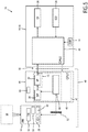
- Fig. 5 shows a further embodiment of an ultrasound imaging system 10. Like elements are denoted with like reference numerals and will not be explained again. This embodiment also provides for the advantage that the console device 18 does not need to comprise any ultrasound specific hardware. Again, a display 26, an input device 28 and a central processing unit 40 in which an application 44 is run to display the display data on the display device 26 is sufficient. Also, the interface 50 may be as previously explained, it may be cable connected.
- the image acquisition device 46 is not solely implemented in the probe 14. Instead, the probe carries the transducer array 32, the micro beam formers 62 and, optionally, a first input device 20. Further, there is provided an intermediate connection device 48 as part of the image acquisition device 46 that is connected via an intermediate interface 52 with the probe 14.
- the intermediate connection device 48 can be portable.
- the intermediate interface 52 may be a cable connection.
- the interface 50 connecting the intermediate connection device with the console device 16, 18 is implemented wirelessly. For example, if the interface 50 is a wireless interface, the UWB technology may be used.
- the interface 52 may also include a power line to power the probe 14 and the intermediate connection device 48 may include a battery for powering both the intermediate connection device 48 and the transducer array 32.
- the intermediate connection device 48 may be powered by a battery. In that case the same battery may also provide power to both the intermediate connection device 48 and probe 14.
- the intermediate connection device 48 may also be provided with a wired power connection.
- Fig. 6 shows a further embodiment similar to that of Fig. 5 .
- the probe 14 also comprises the main beam former 60 and, hence, the whole beam former 34. By this, the size of the probe 14 may be reduced, also.
- the signal processor 36 is located in the intermediate connection device 48.
- the image processor 42 may still be located in the intermediate connection device 48. Alternatively, it may be located in the console device 18.
- Fig. 7 shows a further embodiment similar to that of Fig. 6 .
- the probe 14 also comprises the signal processor 36.
- the size of the probe may be reduced, also.
- the image processor 42 producing some of the heat dissipated by its circuitry may still be located in the intermediate connection device 48.
- Fig. 8 shows a general overview of an embodiment of a kit for ultrasound imaging.
- the ultrasound image acquisition device 46 may be, as in the depicted example, a probe 14 that may be either connected to a mobile console 18 or a cart-based console 16.
- the probe 14 together with the mobile console 18 may form an ultrasound imaging system 10 according to an embodiment.
- the probe 14 connected to the cart-based console 16 may also form an ultrasound imaging system 10.
- a cable connection to the mobile console is depicted with a dashed line designated by reference numeral 74.
- the cabled connection to the cart-based console 16 is indicated via a dashed line designated by reference numeral 72.
- the cart-based console 16 and the mobile console 18 together with the probe 14 may form an ultrasound image acquisition kit 80 that enables a user to selectively attach a single probe 14 to different console devices 16, 18.
- the cart-based console 16 also comprises a display 26' and an input device 28'. Further, the display 26' and the input device 28' are supported by the cart 66 that may be based on wheels 68.
- the cart-based console 60 may comprise further image acquisition and processing hardware assembly 70.
- the further image acquisition and processing hardware assembly 70 may comprise a further signal processor, beam former and/or image processor. This further image acquisition and processing hardware assembly may support and enhance the image acquisition hardware assembly 31 (or extended assembly 38) already provided in the probe.
- sophisticated ultrasound imaging techniques can be provided.
- the probe 14 may be configured such that it may use either an USB 3.0 or 2.0 standard.
- the communication standard USB 2.0 will be automatically be recognized via a handshake procedure of the USB protocol and, hence, the recognition device 54 automatically sets a first operation mode and a first operating state of the image acquisition hardware assembly 31 that uses less power and provides "only" two-dimensional or multiplanar image acquisition.
- the recognition device 54 in the probe 14 recognizes that the console device 16 is a non-portable or cart-based console.
- the ultrasound image acquisition hardware assembly 31 will be set to a second operating state that enables more sophisticated ultrasound imaging, for example three-dimensional ultrasound imaging. Although such a second operating state may consume more power, and has a higher data transfer rate, this is enabled via the USB 3.0 standard and a power line or conductor from the non-portable console 16 to the probe 14.
- Fig. 9 shows a schematic flow diagram of a method 100 according to the invention.
- the ultrasound image acquisition device 10 comprises a transducer array 32 configured to provide an ultrasound receive signal, an image acquisition hardware assembly 31 having a beam former 34 configured to control the transducer array 32, and further configured to receive the ultrasound receive signal and to provide an image signal, and a signal processor 36 configured to receive the image signal and to provide image data, an interface 50 for connecting the ultrasound image acquisition device with a console device 16, 18, and a recognition device 54 for recognizing an operating mode of the ultrasound image acquisition device, wherein the recognition device is further configured to recognize the operating mode depending on a type of the console device and/or an applicable communication standard of the interface.
- the ultrasound image acquisition device 46 is connected to a console device that may be either a mobile console 16 or a cart-based console 18.
- the recognition device 54 recognizes an operating mode depending on a type of the console device 16, 18 via the recognition device 54 of the ultrasound image acquisition device 10.
- An operating state of the image acquisition hardware assembly is set.
- the transducer array 32 and/or the image acquisition hardware assembly 31 are switched between at least two operating states based on the recognized operating mode.
- the specifying method ends in a step 112. Then, ultrasound image acquisition can be conducted in the specified operating state.
- the probe 14 is disconnected from a console device 16, 18 and reconnected to a console device 16, 18, the method starts over and newly recognizes and switches a corresponding operating mode.
- a computer program may be stored/distributed on a suitable medium, such as an optical storage medium or a solid-state medium supplied together with or as part of other hardware, but may also be distributed in other forms, such as via the Internet or other wired or wireless telecommunication systems.
- a suitable medium such as an optical storage medium or a solid-state medium supplied together with or as part of other hardware, but may also be distributed in other forms, such as via the Internet or other wired or wireless telecommunication systems.
Landscapes
- Health & Medical Sciences (AREA)
- Life Sciences & Earth Sciences (AREA)
- Engineering & Computer Science (AREA)
- Physics & Mathematics (AREA)
- Molecular Biology (AREA)
- General Health & Medical Sciences (AREA)
- Nuclear Medicine, Radiotherapy & Molecular Imaging (AREA)
- Pathology (AREA)
- Radiology & Medical Imaging (AREA)
- Biomedical Technology (AREA)
- Heart & Thoracic Surgery (AREA)
- Medical Informatics (AREA)
- Veterinary Medicine (AREA)
- Surgery (AREA)
- Animal Behavior & Ethology (AREA)
- Biophysics (AREA)
- Public Health (AREA)
- Computer Networks & Wireless Communication (AREA)
- Gynecology & Obstetrics (AREA)
- Computer Vision & Pattern Recognition (AREA)
- Computer Graphics (AREA)
- General Engineering & Computer Science (AREA)
- General Physics & Mathematics (AREA)
- Radar, Positioning & Navigation (AREA)
- Remote Sensing (AREA)
- Ultra Sonic Daignosis Equipment (AREA)
- Investigating Or Analyzing Materials By The Use Of Ultrasonic Waves (AREA)
Applications Claiming Priority (2)
| Application Number | Priority Date | Filing Date | Title |
|---|---|---|---|
| US201361774196P | 2013-03-07 | 2013-03-07 | |
| PCT/IB2014/059380 WO2014136030A1 (en) | 2013-03-07 | 2014-03-03 | Multi-purpose ultrasound image acquisition device |
Publications (2)
| Publication Number | Publication Date |
|---|---|
| EP2964095A1 EP2964095A1 (en) | 2016-01-13 |
| EP2964095B1 true EP2964095B1 (en) | 2017-05-10 |
Family
ID=50336370
Family Applications (1)
| Application Number | Title | Priority Date | Filing Date |
|---|---|---|---|
| EP14711315.3A Active EP2964095B1 (en) | 2013-03-07 | 2014-03-03 | Multi-purpose ultrasound image acquisition device |
Country Status (7)
| Country | Link |
|---|---|
| US (3) | US10085723B2 (enExample) |
| EP (1) | EP2964095B1 (enExample) |
| JP (1) | JP6309982B2 (enExample) |
| CN (1) | CN105007826B (enExample) |
| BR (1) | BR112015021282B1 (enExample) |
| RU (1) | RU2677080C2 (enExample) |
| WO (1) | WO2014136030A1 (enExample) |
Families Citing this family (21)
| Publication number | Priority date | Publication date | Assignee | Title |
|---|---|---|---|---|
| US10695034B2 (en) * | 2015-05-15 | 2020-06-30 | Butterfly Network, Inc. | Autonomous ultrasound probe and related apparatus and methods |
| CN105249989B (zh) * | 2015-08-31 | 2018-10-26 | 深圳市红源资产管理有限公司 | 基于单总线通信的超声探头识别方法及超声医疗设备 |
| JP6382174B2 (ja) * | 2015-11-13 | 2018-08-29 | 日本光電工業株式会社 | 生体情報モニタ、生体情報測定システム、及びプログラム |
| CN106200484B (zh) * | 2016-08-05 | 2019-08-13 | 东软医疗系统股份有限公司 | 电机控制系统及方法 |
| US11446003B2 (en) | 2017-03-27 | 2022-09-20 | Vave Health, Inc. | High performance handheld ultrasound |
| US10856843B2 (en) | 2017-03-23 | 2020-12-08 | Vave Health, Inc. | Flag table based beamforming in a handheld ultrasound device |
| US11531096B2 (en) | 2017-03-23 | 2022-12-20 | Vave Health, Inc. | High performance handheld ultrasound |
| US10469846B2 (en) | 2017-03-27 | 2019-11-05 | Vave Health, Inc. | Dynamic range compression of ultrasound images |
| CN111065338B (zh) * | 2017-08-10 | 2024-04-26 | 皇家飞利浦有限公司 | 用于超声成像系统的连接器 |
| WO2019087706A1 (ja) * | 2017-10-30 | 2019-05-09 | 株式会社フジキン | 超音波プローブ |
| EP3513733A1 (en) * | 2018-01-23 | 2019-07-24 | Koninklijke Philips N.V. | Ultrasound imaging apparatus and method |
| WO2019173152A1 (en) | 2018-03-05 | 2019-09-12 | Exo Imaging, Inc. | Thumb-dominant ultrasound imaging system |
| US10685439B2 (en) | 2018-06-27 | 2020-06-16 | General Electric Company | Imaging system and method providing scalable resolution in multi-dimensional image data |
| EP3649959A1 (en) * | 2018-11-06 | 2020-05-13 | Koninklijke Philips N.V. | Ultrasound control unit |
| JP2022522963A (ja) | 2019-01-15 | 2022-04-21 | 3シェイプ アー/エス | 無線走査装置 |
| CN110742639B (zh) * | 2019-10-25 | 2023-09-05 | 上海联影医疗科技股份有限公司 | 扫描系统配置方法、装置、计算机设备和可读存储介质 |
| CA3176305A1 (en) | 2020-05-22 | 2021-11-25 | Mike HUIE | Product registration system |
| CN114680921A (zh) * | 2020-12-29 | 2022-07-01 | 无锡祥生医疗科技股份有限公司 | 超声探头识别适配方法、装置、超声设备和存储介质 |
| CN112932534B (zh) * | 2021-01-27 | 2022-02-22 | 深圳华声医疗技术股份有限公司 | 超声图像采集处理系统和超声图像采集处理方法 |
| JP7705777B2 (ja) | 2021-10-15 | 2025-07-10 | 富士フイルム株式会社 | 超音波システム、超音波プローブ、超音波システムの制御方法および超音波プローブの制御方法 |
| CN114533119B (zh) * | 2022-03-03 | 2024-12-31 | 意领科技有限公司 | 拓展超声成像设备的功能的方法和系统 |
Family Cites Families (38)
| Publication number | Priority date | Publication date | Assignee | Title |
|---|---|---|---|---|
| US6279399B1 (en) * | 1998-08-03 | 2001-08-28 | Vingmed Sound A/S | Multi-dimensional transducer array apparatus |
| US6364839B1 (en) * | 1999-05-04 | 2002-04-02 | Sonosite, Inc. | Ultrasound diagnostic instrument having software in detachable scanhead |
| US6440072B1 (en) | 2000-03-30 | 2002-08-27 | Acuson Corporation | Medical diagnostic ultrasound imaging system and method for transferring ultrasound examination data to a portable computing device |
| US6602194B2 (en) | 2000-09-15 | 2003-08-05 | Koninklijke Philips Electronics N.V. | Dual beamformer ultrasound system for 2D and 3D imaging |
| US6540682B1 (en) | 2000-11-09 | 2003-04-01 | Koninklijke Philips Electronics N.V. | Portable, configurable and scalable ultrasound imaging system |
| US7127678B2 (en) * | 2000-12-21 | 2006-10-24 | Microsoft Corporation | System and method to specify device specific user interface information in the firmware of a USB device |
| US6475146B1 (en) | 2001-09-24 | 2002-11-05 | Siemens Medical Solutions Usa, Inc. | Method and system for using personal digital assistants with diagnostic medical ultrasound systems |
| US7141020B2 (en) | 2002-02-20 | 2006-11-28 | Koninklijke Philips Electronics N.V. | Portable 3D ultrasound system |
| US20040123106A1 (en) * | 2002-08-27 | 2004-06-24 | Lexent Technologies, Inc. | Apparatus and methods for motion and proximity enhanced remote identity broadcast with biometric authentication |
| JP2005071273A (ja) * | 2003-08-27 | 2005-03-17 | Canon Inc | 電子機器及びそのインターフェース制御方法 |
| EP1695113A2 (en) * | 2003-11-26 | 2006-08-30 | Teratech Corporation | Modular portable ultrasound systems |
| WO2006011873A1 (en) | 2004-06-30 | 2006-02-02 | Albemarle Corporation | Cracking of dicyclopentadiene |
| US7996688B2 (en) * | 2004-08-24 | 2011-08-09 | Sonosite, Inc. | Ultrasound system power management |
| US8658453B2 (en) * | 2004-09-15 | 2014-02-25 | Sonetics Ultrasound, Inc. | Capacitive micromachined ultrasonic transducer |
| CN101061452A (zh) * | 2004-11-22 | 2007-10-24 | 皇家飞利浦电子股份有限公司 | 可变功耗的便携式超声系统 |
| KR100750117B1 (ko) * | 2005-01-19 | 2007-08-21 | 삼성전자주식회사 | Usb 디바이스의 클래스 설정 방법 및 장치 |
| WO2006111872A2 (en) | 2005-04-18 | 2006-10-26 | Koninklijke Philips Electronics, N.V. | Pc-based portable ultrasonic diagnostic imaging system |
| WO2006111873A2 (en) | 2005-04-18 | 2006-10-26 | Koninklijke Philips Electronics, N.V. | Ultrasonic diagnostic imaging system configured by probe firmware |
| RU2445007C2 (ru) * | 2006-05-24 | 2012-03-20 | Конинклейке Филипс Электроникс, Н.В. | Совмещение систем координат |
| US8396804B1 (en) * | 2006-07-19 | 2013-03-12 | Mvisum, Inc. | System for remote review of clinical data |
| US20080146922A1 (en) * | 2006-10-24 | 2008-06-19 | Zonare Medical Systems, Inc. | Control of user interfaces and displays for portable ultrasound unit and docking station |
| US20080112265A1 (en) * | 2006-11-10 | 2008-05-15 | Penrith Corporation | Transducer array imaging system |
| US8600299B2 (en) * | 2006-11-10 | 2013-12-03 | Siemens Medical Solutions Usa, Inc. | Transducer array imaging system |
| ES2397553T3 (es) * | 2007-04-10 | 2013-03-07 | C.R.Bard, Inc. | Sistema de ultrasonidos de baja potencia |
| EP2164397B1 (en) * | 2007-06-01 | 2019-03-27 | Koninklijke Philips N.V. | Wireless ultrasound probe user interface |
| JP5727785B2 (ja) * | 2007-06-01 | 2015-06-03 | コーニンクレッカ フィリップス エヌ ヴェ | 無線超音波プローブケーブル |
| WO2009077983A1 (en) * | 2007-12-17 | 2009-06-25 | Koninklijke Philips Electronics, N.V. | Apparatus, systems and methods for ultrasound imaging |
| WO2009105961A1 (zh) * | 2008-02-25 | 2009-09-03 | Wang Shucai | 一种超声诊断机器 |
| EP2296552A1 (en) | 2008-05-29 | 2011-03-23 | Koninklijke Philips Electronics N.V. | Tissue strain analysis |
| US8162958B2 (en) | 2008-07-11 | 2012-04-24 | Olympus Medical Systems Corp. | Tissue fastening tool and applicator for indwelling the same within body, and tissue fastening method through natural orifice |
| US8172753B2 (en) * | 2008-07-11 | 2012-05-08 | General Electric Company | Systems and methods for visualization of an ultrasound probe relative to an object |
| JP5367431B2 (ja) * | 2009-03-27 | 2013-12-11 | 富士フイルム株式会社 | 超音波プローブ及び超音波プローブシステム |
| US8465428B2 (en) * | 2009-03-27 | 2013-06-18 | Fujifilm Corporation | Ultrasonic probe and ultrasonic probe system |
| JP5758375B2 (ja) | 2009-04-01 | 2015-08-05 | アナロジック コーポレイション | 超音波プローブ |
| JP5566766B2 (ja) * | 2009-05-29 | 2014-08-06 | 株式会社東芝 | 超音波診断装置、画像表示装置、画像表示方法、表示方法 |
| US9949718B2 (en) * | 2010-07-12 | 2018-04-24 | General Electric Company | Method and system for controlling communication of data via digital demodulation in a diagnostic ultrasound system |
| US20120099773A1 (en) * | 2010-10-20 | 2012-04-26 | General Electric Company | Method to Achieve Frame Rate or Resolution in Diagnostic Ultrasound |
| JP5134721B1 (ja) * | 2011-11-28 | 2013-01-30 | 株式会社東芝 | ポータブル超音波診断装置 |
-
2014
- 2014-03-03 CN CN201480012718.0A patent/CN105007826B/zh active Active
- 2014-03-03 JP JP2015560822A patent/JP6309982B2/ja not_active Expired - Fee Related
- 2014-03-03 BR BR112015021282-4A patent/BR112015021282B1/pt not_active IP Right Cessation
- 2014-03-03 RU RU2015142479A patent/RU2677080C2/ru active
- 2014-03-03 WO PCT/IB2014/059380 patent/WO2014136030A1/en not_active Ceased
- 2014-03-03 US US14/772,111 patent/US10085723B2/en active Active
- 2014-03-03 EP EP14711315.3A patent/EP2964095B1/en active Active
-
2018
- 2018-09-17 US US16/132,836 patent/US11992371B2/en active Active
-
2024
- 2024-04-23 US US18/643,141 patent/US12508005B2/en active Active
Also Published As
| Publication number | Publication date |
|---|---|
| CN105007826B (zh) | 2018-03-27 |
| US20240268795A1 (en) | 2024-08-15 |
| US10085723B2 (en) | 2018-10-02 |
| CN105007826A (zh) | 2015-10-28 |
| US11992371B2 (en) | 2024-05-28 |
| EP2964095A1 (en) | 2016-01-13 |
| BR112015021282B1 (pt) | 2022-01-25 |
| JP2016512446A (ja) | 2016-04-28 |
| RU2677080C2 (ru) | 2019-01-15 |
| US20190015079A1 (en) | 2019-01-17 |
| WO2014136030A1 (en) | 2014-09-12 |
| US12508005B2 (en) | 2025-12-30 |
| JP6309982B2 (ja) | 2018-04-11 |
| US20160015368A1 (en) | 2016-01-21 |
| RU2015142479A (ru) | 2017-04-12 |
| BR112015021282A2 (pt) | 2017-07-18 |
Similar Documents
| Publication | Publication Date | Title |
|---|---|---|
| US12508005B2 (en) | Multi-purpose ultrasound image acquisition device | |
| EP2895075B1 (en) | Mobile 3d wireless ultrasound image acquisition device and ultrasound imaging system | |
| RU2720290C2 (ru) | Ультразвуковая система с процессорным электронным ключом | |
| EP3335636B1 (en) | Probe apparatus, medical instrument comprising same, and control method of probe apparatus | |
| CN106999149B (zh) | 多传感器超声探头及相关方法 | |
| CN108294779B (zh) | 超声波探头、超声波成像装置和控制超声波成像装置方法 | |
| CN105796127B (zh) | 探头组件、超声成像设备以及超声成像设备的控制方法 | |
| EP2510880A1 (en) | Ultrasound diagnostic system | |
| CN103284757A (zh) | 用于执行超声成像的方法和设备 | |
| KR102646992B1 (ko) | 초음파 프로브, 초음파 프로브의 제어 방법 및 초음파 프로브를 포함하는 초음파 영상 장치 | |
| CN115209813A (zh) | 具有显示器保持部的手持式超声扫描器及相关装置、系统和方法 | |
| US10130335B2 (en) | Ultrasonic diagnostic system | |
| CN102228383A (zh) | 一种显示型超声探头及其显示方法 | |
| CN116636875A (zh) | 用于超声采集的数据传送的方法和系统 | |
| EP4088665A1 (en) | Dematerialized, multi-user system for the acquisition, generation and processing of ultrasound images | |
| WO2009077983A1 (en) | Apparatus, systems and methods for ultrasound imaging | |
| CN112971845B (zh) | 超声诊断设备及其控制方法 | |
| US11730449B2 (en) | Ultrasonic diagnostic system | |
| WO2014041468A1 (en) | Mobilete 3d ultrasound image acquisition device and ultrasound imaging system | |
| EP4534215A1 (en) | Ultrasound probe, method of manufacturing the same, and structure combinable with main backing layer of the same | |
| KR20200001736A (ko) | 초음파 영상의 디스플레이 장치와 시스템 및 이를 이용한 생체조직의 사이즈 검출방법 | |
| JP2006255102A (ja) | 超音波探触子および超音波診断装置 | |
| WO2015070550A1 (zh) | 一种乳腺超声机及超声诊断系统 |
Legal Events
| Date | Code | Title | Description |
|---|---|---|---|
| PUAI | Public reference made under article 153(3) epc to a published international application that has entered the european phase |
Free format text: ORIGINAL CODE: 0009012 |
|
| 17P | Request for examination filed |
Effective date: 20151007 |
|
| AK | Designated contracting states |
Kind code of ref document: A1 Designated state(s): AL AT BE BG CH CY CZ DE DK EE ES FI FR GB GR HR HU IE IS IT LI LT LU LV MC MK MT NL NO PL PT RO RS SE SI SK SM TR |
|
| AX | Request for extension of the european patent |
Extension state: BA ME |
|
| DAX | Request for extension of the european patent (deleted) | ||
| REG | Reference to a national code |
Ref country code: DE Ref legal event code: R079 Ref document number: 602014009660 Country of ref document: DE Free format text: PREVIOUS MAIN CLASS: A61B0008000000 Ipc: A61B0008140000 |
|
| GRAP | Despatch of communication of intention to grant a patent |
Free format text: ORIGINAL CODE: EPIDOSNIGR1 |
|
| RIC1 | Information provided on ipc code assigned before grant |
Ipc: A61B 8/08 20060101ALI20160928BHEP Ipc: A61B 8/14 20060101AFI20160928BHEP Ipc: A61B 8/00 20060101ALI20160928BHEP |
|
| INTG | Intention to grant announced |
Effective date: 20161026 |
|
| RIN1 | Information on inventor provided before grant (corrected) |
Inventor name: POLAND, MCKEE DUNN |
|
| GRAS | Grant fee paid |
Free format text: ORIGINAL CODE: EPIDOSNIGR3 |
|
| GRAA | (expected) grant |
Free format text: ORIGINAL CODE: 0009210 |
|
| AK | Designated contracting states |
Kind code of ref document: B1 Designated state(s): AL AT BE BG CH CY CZ DE DK EE ES FI FR GB GR HR HU IE IS IT LI LT LU LV MC MK MT NL NO PL PT RO RS SE SI SK SM TR |
|
| REG | Reference to a national code |
Ref country code: GB Ref legal event code: FG4D |
|
| REG | Reference to a national code |
Ref country code: AT Ref legal event code: REF Ref document number: 891458 Country of ref document: AT Kind code of ref document: T Effective date: 20170515 Ref country code: CH Ref legal event code: EP |
|
| REG | Reference to a national code |
Ref country code: IE Ref legal event code: FG4D |
|
| REG | Reference to a national code |
Ref country code: DE Ref legal event code: R096 Ref document number: 602014009660 Country of ref document: DE |
|
| REG | Reference to a national code |
Ref country code: DE Ref legal event code: R084 Ref document number: 602014009660 Country of ref document: DE |
|
| REG | Reference to a national code |
Ref country code: GB Ref legal event code: 746 Effective date: 20170822 Ref country code: NL Ref legal event code: MP Effective date: 20170510 |
|
| REG | Reference to a national code |
Ref country code: LT Ref legal event code: MG4D |
|
| REG | Reference to a national code |
Ref country code: AT Ref legal event code: MK05 Ref document number: 891458 Country of ref document: AT Kind code of ref document: T Effective date: 20170510 |
|
| PG25 | Lapsed in a contracting state [announced via postgrant information from national office to epo] |
Ref country code: FI Free format text: LAPSE BECAUSE OF FAILURE TO SUBMIT A TRANSLATION OF THE DESCRIPTION OR TO PAY THE FEE WITHIN THE PRESCRIBED TIME-LIMIT Effective date: 20170510 Ref country code: GR Free format text: LAPSE BECAUSE OF FAILURE TO SUBMIT A TRANSLATION OF THE DESCRIPTION OR TO PAY THE FEE WITHIN THE PRESCRIBED TIME-LIMIT Effective date: 20170811 Ref country code: LT Free format text: LAPSE BECAUSE OF FAILURE TO SUBMIT A TRANSLATION OF THE DESCRIPTION OR TO PAY THE FEE WITHIN THE PRESCRIBED TIME-LIMIT Effective date: 20170510 Ref country code: AT Free format text: LAPSE BECAUSE OF FAILURE TO SUBMIT A TRANSLATION OF THE DESCRIPTION OR TO PAY THE FEE WITHIN THE PRESCRIBED TIME-LIMIT Effective date: 20170510 Ref country code: ES Free format text: LAPSE BECAUSE OF FAILURE TO SUBMIT A TRANSLATION OF THE DESCRIPTION OR TO PAY THE FEE WITHIN THE PRESCRIBED TIME-LIMIT Effective date: 20170510 Ref country code: HR Free format text: LAPSE BECAUSE OF FAILURE TO SUBMIT A TRANSLATION OF THE DESCRIPTION OR TO PAY THE FEE WITHIN THE PRESCRIBED TIME-LIMIT Effective date: 20170510 Ref country code: NO Free format text: LAPSE BECAUSE OF FAILURE TO SUBMIT A TRANSLATION OF THE DESCRIPTION OR TO PAY THE FEE WITHIN THE PRESCRIBED TIME-LIMIT Effective date: 20170810 |
|
| PG25 | Lapsed in a contracting state [announced via postgrant information from national office to epo] |
Ref country code: IS Free format text: LAPSE BECAUSE OF FAILURE TO SUBMIT A TRANSLATION OF THE DESCRIPTION OR TO PAY THE FEE WITHIN THE PRESCRIBED TIME-LIMIT Effective date: 20170910 Ref country code: RS Free format text: LAPSE BECAUSE OF FAILURE TO SUBMIT A TRANSLATION OF THE DESCRIPTION OR TO PAY THE FEE WITHIN THE PRESCRIBED TIME-LIMIT Effective date: 20170510 Ref country code: PL Free format text: LAPSE BECAUSE OF FAILURE TO SUBMIT A TRANSLATION OF THE DESCRIPTION OR TO PAY THE FEE WITHIN THE PRESCRIBED TIME-LIMIT Effective date: 20170510 Ref country code: NL Free format text: LAPSE BECAUSE OF FAILURE TO SUBMIT A TRANSLATION OF THE DESCRIPTION OR TO PAY THE FEE WITHIN THE PRESCRIBED TIME-LIMIT Effective date: 20170510 Ref country code: LV Free format text: LAPSE BECAUSE OF FAILURE TO SUBMIT A TRANSLATION OF THE DESCRIPTION OR TO PAY THE FEE WITHIN THE PRESCRIBED TIME-LIMIT Effective date: 20170510 Ref country code: BG Free format text: LAPSE BECAUSE OF FAILURE TO SUBMIT A TRANSLATION OF THE DESCRIPTION OR TO PAY THE FEE WITHIN THE PRESCRIBED TIME-LIMIT Effective date: 20170810 Ref country code: SE Free format text: LAPSE BECAUSE OF FAILURE TO SUBMIT A TRANSLATION OF THE DESCRIPTION OR TO PAY THE FEE WITHIN THE PRESCRIBED TIME-LIMIT Effective date: 20170510 |
|
| PG25 | Lapsed in a contracting state [announced via postgrant information from national office to epo] |
Ref country code: RO Free format text: LAPSE BECAUSE OF FAILURE TO SUBMIT A TRANSLATION OF THE DESCRIPTION OR TO PAY THE FEE WITHIN THE PRESCRIBED TIME-LIMIT Effective date: 20170510 Ref country code: SK Free format text: LAPSE BECAUSE OF FAILURE TO SUBMIT A TRANSLATION OF THE DESCRIPTION OR TO PAY THE FEE WITHIN THE PRESCRIBED TIME-LIMIT Effective date: 20170510 Ref country code: DK Free format text: LAPSE BECAUSE OF FAILURE TO SUBMIT A TRANSLATION OF THE DESCRIPTION OR TO PAY THE FEE WITHIN THE PRESCRIBED TIME-LIMIT Effective date: 20170510 Ref country code: CZ Free format text: LAPSE BECAUSE OF FAILURE TO SUBMIT A TRANSLATION OF THE DESCRIPTION OR TO PAY THE FEE WITHIN THE PRESCRIBED TIME-LIMIT Effective date: 20170510 Ref country code: EE Free format text: LAPSE BECAUSE OF FAILURE TO SUBMIT A TRANSLATION OF THE DESCRIPTION OR TO PAY THE FEE WITHIN THE PRESCRIBED TIME-LIMIT Effective date: 20170510 |
|
| REG | Reference to a national code |
Ref country code: DE Ref legal event code: R097 Ref document number: 602014009660 Country of ref document: DE |
|
| PG25 | Lapsed in a contracting state [announced via postgrant information from national office to epo] |
Ref country code: SM Free format text: LAPSE BECAUSE OF FAILURE TO SUBMIT A TRANSLATION OF THE DESCRIPTION OR TO PAY THE FEE WITHIN THE PRESCRIBED TIME-LIMIT Effective date: 20170510 |
|
| PLBE | No opposition filed within time limit |
Free format text: ORIGINAL CODE: 0009261 |
|
| STAA | Information on the status of an ep patent application or granted ep patent |
Free format text: STATUS: NO OPPOSITION FILED WITHIN TIME LIMIT |
|
| REG | Reference to a national code |
Ref country code: FR Ref legal event code: PLFP Year of fee payment: 5 |
|
| 26N | No opposition filed |
Effective date: 20180213 |
|
| PG25 | Lapsed in a contracting state [announced via postgrant information from national office to epo] |
Ref country code: SI Free format text: LAPSE BECAUSE OF FAILURE TO SUBMIT A TRANSLATION OF THE DESCRIPTION OR TO PAY THE FEE WITHIN THE PRESCRIBED TIME-LIMIT Effective date: 20170510 |
|
| REG | Reference to a national code |
Ref country code: CH Ref legal event code: PL |
|
| PG25 | Lapsed in a contracting state [announced via postgrant information from national office to epo] |
Ref country code: MC Free format text: LAPSE BECAUSE OF FAILURE TO SUBMIT A TRANSLATION OF THE DESCRIPTION OR TO PAY THE FEE WITHIN THE PRESCRIBED TIME-LIMIT Effective date: 20170510 |
|
| REG | Reference to a national code |
Ref country code: BE Ref legal event code: MM Effective date: 20180331 |
|
| REG | Reference to a national code |
Ref country code: IE Ref legal event code: MM4A |
|
| PG25 | Lapsed in a contracting state [announced via postgrant information from national office to epo] |
Ref country code: LU Free format text: LAPSE BECAUSE OF NON-PAYMENT OF DUE FEES Effective date: 20180303 |
|
| PG25 | Lapsed in a contracting state [announced via postgrant information from national office to epo] |
Ref country code: IE Free format text: LAPSE BECAUSE OF NON-PAYMENT OF DUE FEES Effective date: 20180303 |
|
| PG25 | Lapsed in a contracting state [announced via postgrant information from national office to epo] |
Ref country code: BE Free format text: LAPSE BECAUSE OF NON-PAYMENT OF DUE FEES Effective date: 20180331 Ref country code: CH Free format text: LAPSE BECAUSE OF NON-PAYMENT OF DUE FEES Effective date: 20180331 Ref country code: LI Free format text: LAPSE BECAUSE OF NON-PAYMENT OF DUE FEES Effective date: 20180331 |
|
| PG25 | Lapsed in a contracting state [announced via postgrant information from national office to epo] |
Ref country code: MT Free format text: LAPSE BECAUSE OF NON-PAYMENT OF DUE FEES Effective date: 20180303 |
|
| PG25 | Lapsed in a contracting state [announced via postgrant information from national office to epo] |
Ref country code: TR Free format text: LAPSE BECAUSE OF FAILURE TO SUBMIT A TRANSLATION OF THE DESCRIPTION OR TO PAY THE FEE WITHIN THE PRESCRIBED TIME-LIMIT Effective date: 20170510 |
|
| PG25 | Lapsed in a contracting state [announced via postgrant information from national office to epo] |
Ref country code: PT Free format text: LAPSE BECAUSE OF FAILURE TO SUBMIT A TRANSLATION OF THE DESCRIPTION OR TO PAY THE FEE WITHIN THE PRESCRIBED TIME-LIMIT Effective date: 20170510 |
|
| PG25 | Lapsed in a contracting state [announced via postgrant information from national office to epo] |
Ref country code: HU Free format text: LAPSE BECAUSE OF FAILURE TO SUBMIT A TRANSLATION OF THE DESCRIPTION OR TO PAY THE FEE WITHIN THE PRESCRIBED TIME-LIMIT; INVALID AB INITIO Effective date: 20140303 Ref country code: MK Free format text: LAPSE BECAUSE OF NON-PAYMENT OF DUE FEES Effective date: 20170510 Ref country code: CY Free format text: LAPSE BECAUSE OF FAILURE TO SUBMIT A TRANSLATION OF THE DESCRIPTION OR TO PAY THE FEE WITHIN THE PRESCRIBED TIME-LIMIT Effective date: 20170510 |
|
| PG25 | Lapsed in a contracting state [announced via postgrant information from national office to epo] |
Ref country code: AL Free format text: LAPSE BECAUSE OF FAILURE TO SUBMIT A TRANSLATION OF THE DESCRIPTION OR TO PAY THE FEE WITHIN THE PRESCRIBED TIME-LIMIT Effective date: 20170510 |
|
| PGFP | Annual fee paid to national office [announced via postgrant information from national office to epo] |
Ref country code: FR Payment date: 20230323 Year of fee payment: 10 |
|
| PGFP | Annual fee paid to national office [announced via postgrant information from national office to epo] |
Ref country code: GB Payment date: 20240319 Year of fee payment: 11 |
|
| PGFP | Annual fee paid to national office [announced via postgrant information from national office to epo] |
Ref country code: IT Payment date: 20240321 Year of fee payment: 11 |
|
| PG25 | Lapsed in a contracting state [announced via postgrant information from national office to epo] |
Ref country code: FR Free format text: LAPSE BECAUSE OF NON-PAYMENT OF DUE FEES Effective date: 20240331 |
|
| PG25 | Lapsed in a contracting state [announced via postgrant information from national office to epo] |
Ref country code: FR Free format text: LAPSE BECAUSE OF NON-PAYMENT OF DUE FEES Effective date: 20240331 |
|
| PGFP | Annual fee paid to national office [announced via postgrant information from national office to epo] |
Ref country code: DE Payment date: 20250327 Year of fee payment: 12 |
|
| GBPC | Gb: european patent ceased through non-payment of renewal fee |
Effective date: 20250303 |
|
| PG25 | Lapsed in a contracting state [announced via postgrant information from national office to epo] |
Ref country code: GB Free format text: LAPSE BECAUSE OF NON-PAYMENT OF DUE FEES Effective date: 20250303 |
|
| PG25 | Lapsed in a contracting state [announced via postgrant information from national office to epo] |
Ref country code: IT Free format text: LAPSE BECAUSE OF NON-PAYMENT OF DUE FEES Effective date: 20250303 |