EP2963867B1 - Verfahren, system und vorrichtung zur herstellung von pseudodraht - Google Patents
Verfahren, system und vorrichtung zur herstellung von pseudodraht Download PDFInfo
- Publication number
- EP2963867B1 EP2963867B1 EP15176388.5A EP15176388A EP2963867B1 EP 2963867 B1 EP2963867 B1 EP 2963867B1 EP 15176388 A EP15176388 A EP 15176388A EP 2963867 B1 EP2963867 B1 EP 2963867B1
- Authority
- EP
- European Patent Office
- Prior art keywords
- information
- provider edge
- pseudo
- switching provider
- active
- Prior art date
- Legal status (The legal status is an assumption and is not a legal conclusion. Google has not performed a legal analysis and makes no representation as to the accuracy of the status listed.)
- Not-in-force
Links
- 238000000034 method Methods 0.000 title claims description 62
- 238000013507 mapping Methods 0.000 claims description 78
- 229920002725 thermoplastic elastomer Polymers 0.000 description 51
- 235000008694 Humulus lupulus Nutrition 0.000 description 32
- 101100028962 Saccharomyces cerevisiae (strain ATCC 204508 / S288c) PDR1 gene Proteins 0.000 description 22
- 101100366333 Arabidopsis thaliana ADC2 gene Proteins 0.000 description 17
- 101150089804 SPE2 gene Proteins 0.000 description 17
- 238000010586 diagram Methods 0.000 description 17
- 230000011664 signaling Effects 0.000 description 15
- 238000011084 recovery Methods 0.000 description 6
- 238000004891 communication Methods 0.000 description 5
- 238000009792 diffusion process Methods 0.000 description 5
- 230000006855 networking Effects 0.000 description 4
- 101100366322 Arabidopsis thaliana ADC1 gene Proteins 0.000 description 3
- 101150032645 SPE1 gene Proteins 0.000 description 3
- 238000005516 engineering process Methods 0.000 description 3
- 108010001267 Protein Subunits Proteins 0.000 description 2
- 238000012986 modification Methods 0.000 description 1
- 230000004048 modification Effects 0.000 description 1
- 230000003287 optical effect Effects 0.000 description 1
- 238000002360 preparation method Methods 0.000 description 1
Images


Classifications
-
- H—ELECTRICITY
- H04—ELECTRIC COMMUNICATION TECHNIQUE
- H04L—TRANSMISSION OF DIGITAL INFORMATION, e.g. TELEGRAPHIC COMMUNICATION
- H04L45/00—Routing or path finding of packets in data switching networks
- H04L45/68—Pseudowire emulation, e.g. IETF WG PWE3
-
- H—ELECTRICITY
- H04—ELECTRIC COMMUNICATION TECHNIQUE
- H04L—TRANSMISSION OF DIGITAL INFORMATION, e.g. TELEGRAPHIC COMMUNICATION
- H04L45/00—Routing or path finding of packets in data switching networks
- H04L45/22—Alternate routing
-
- H—ELECTRICITY
- H04—ELECTRIC COMMUNICATION TECHNIQUE
- H04L—TRANSMISSION OF DIGITAL INFORMATION, e.g. TELEGRAPHIC COMMUNICATION
- H04L45/00—Routing or path finding of packets in data switching networks
- H04L45/28—Routing or path finding of packets in data switching networks using route fault recovery
-
- H—ELECTRICITY
- H04—ELECTRIC COMMUNICATION TECHNIQUE
- H04L—TRANSMISSION OF DIGITAL INFORMATION, e.g. TELEGRAPHIC COMMUNICATION
- H04L45/00—Routing or path finding of packets in data switching networks
- H04L45/50—Routing or path finding of packets in data switching networks using label swapping, e.g. multi-protocol label switch [MPLS]
-
- H—ELECTRICITY
- H04—ELECTRIC COMMUNICATION TECHNIQUE
- H04L—TRANSMISSION OF DIGITAL INFORMATION, e.g. TELEGRAPHIC COMMUNICATION
- H04L45/00—Routing or path finding of packets in data switching networks
- H04L45/74—Address processing for routing
- H04L45/745—Address table lookup; Address filtering
Definitions
- the present invention relates to the field of communications technologies, and in particular, to a method, a system, and a device for establishing a pseudo wire.
- a network constructed by using a large number of single-segment pseudo wires brings great pressure on a service convergence device.
- a multi-segment pseudo-wire (Multi-Segment Pseudo-Wire, MS-PW) technology is proposed in the field of pseudo-wire emulation edge to edge (Pseudo-Wire Emulation Edge to Edge, PWE3) technologies, where a switching provider edge (Switching PE, S-PE, hereinafter referred to as SPE) is mainly used to relieve pressure of a convergence device and solve cross-domain deployment and security problems of a network.
- Switching PE switching PE
- SPE switching provider edge
- TPE1 Terminating Provider Edge
- SPE3 and a TPE4 pseudo-wire connections to a TPE3 and a TPE4 respectively by passing through an SPE1 and an SPE2 are established.
- a pseudo wire between PEs is established through the following steps:
- an active/standby pseudo wire switchover is performed. In this way, the active/standby pseudo wire switchover can only be completed from a local TPE to a peer TPE, so that a pseudo wire protection switchover between customer edges lasts for a long time.
- US 2010/0098094 A1 discloses a method for setting up at least two pseudo-wires able to broadcast a stream of data, wherein a first pseudo-wire is set up between an input router of a packet-switched network and first output router of the packet-switched network, and a second pseudo-wire is set up between the input router and a second output router of the packet-switched network.
- a first link of the first pseudo-wire is set up between the first output router and an intermediate router of the packet-switched network.
- a second link of the second pseudo-wire is set up between the second output router and the intermediate router.
- a third link of both pseudo-wires is set up between the intermediate router and the input router.
- Embodiments of the present invention provide a method, a system, and a device for establishing a pseudo wire, to speed up a procedure of a pseudo wire protection switchover between customer edges and save a network resource.
- An embodiment of the present invention provides a method for establishing a pseudo wire, where the method includes:
- An embodiment of the present invention provides a switching provider edge, including:
- An embodiment of the present invention provides a terminating provider edge TPE of a service provider, including:
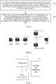
- a method for establishing a pseudo wire is provided, and the method in this embodiment is applicable to an MS-PW system as shown in FIG. 1a , where within a multi-segment pseudo wire MS-PW between a CE1 and a CE2, a switching provider edge SPE2 is connected to two different TPEs respectively; and is also applicable to an MS-PW system as shown in FIG. 1b , where a switching provider edge SPE2 may reach a TPE2 through different outgoing interfaces.
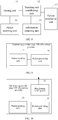
- FIG. 2 A flow chart of the method in this embodiment is shown in FIG. 2 , where the method includes:
- At least two pseudo wires are established from the switching provider edge according to the information of at least two next hops or at least two outgoing interfaces. Specifically, one pseudo wire may be established between the switching provider edge and a TPE device that is corresponding to information of each next-hop address, or one pseudo wire is established between the switching provider edge and a next-hop TPE device respectively through at least two outgoing interfaces.
- the number of established pseudo wires is less than or equal to the number of next hops, or less than or equal to the number of outgoing interfaces. For example, when information of four next hops exists, two, three or four pseudo wires may be established.
- one of the pseudo wires may be set as an active pseudo wire, and another pseudo wire may be set as a standby pseudo wire according to a preset policy. In this way, after the pseudo wires are established, when the switching provider edge at the bifurcation position determines that the active pseudo wire is faulty, a fast protection switchover of the pseudo wires may be directly performed.
- the method for establishing a pseudo wire in this embodiment is applicable to pseudo wire establishment in an MS-PW system, and includes: receiving, by a switching provider edge, a label mapping message sent by a TPE that is directly connected to a customer edge; obtaining information of a switching provider edge at a bifurcation position and information of at least two next hops or at least two outgoing interfaces of the switching provider edge through parsing, and establishing at least two pseudo wires from the switching provider edge according to the information of at least two next hops or at least two outgoing interfaces.
- the TPE only needs to send one label mapping message to establish at least two pseudo wires.
- the TPE sends one label mapping message to establish one pseudo wire
- the method for establishing a pseudo wire in this embodiment, multiple pseudo wires from the switching provider edge at the bifurcation position to a destination node are established. In this way, a resource consumed by pseudo wire establishment can be reduced.
- the switching provider edge at the bifurcation position establishes two pseudo wires and completes establishment of multiple MS-PW segments, and furthermore, an identification of an active/standby MS-PW segment may be implemented.
- a fast protection switchover of an MS-PW may be implemented on the switching provider edge. In this way, a fast recovery procedure of a pseudo wire is speeded up, and segment protection of the MS-PW can be provided from the switching provider edge at the bifurcation position, thereby making better use of a network resource.
- the switching provider edge may further obtain active/standby relationship information of the at least two pseudo wires, and establish at least two pseudo wires according to the active/standby relationship information.
- the information may be obtained by directly parsing information in Sub-TLV in a received label mapping message, and may also be obtained by receiving an active/standby pseudo wire information notification sent by a customer edge and parsing active/standby pseudo wire information in the active/standby pseudo wire information notification, and may also be obtained according to a preset policy, which is not intended to limit the embodiments of the present invention.
- a method for establishing a pseudo wire is provided, and the method in this embodiment is applicable to an MS-PW system as shown in FIG. 1a , where within a multi-segment pseudo wire MS-PW between a CE1 and a CE2, a switching provider edge SPE2 is connected to two different TPEs respectively; and is also applicable to an MS-PW system as shown in FIG. 1b , where a switching provider edge SPE2 may reach a TPE2 through different outgoing interfaces.
- FIG. 3 A flow chart of the method in this embodiment is shown in FIG. 3 , where the method includes:
- the method for establishing a pseudo wire is as described in the first method embodiment, and is not described here again.
- the TPE may also carry, in the Sub-TLV in the label mapping message, active/standby relationship information of a multi-segment pseudo wire between customer edges.
- the switching provider edge at the bifurcation position sets at least two pseudo wires according to the active/standby relationship information.
- the TPE may also send an active/standby pseudo wire information notification to the switching provider edge to notify an active/standby condition of at least two pseudo wires that are established from the switching provider edge at the bifurcation position.
- the switching provider edge that matches with the information of the switching provider edge at the bifurcation position establishes at least two pseudo wires according to the active/standby pseudo wire information notification.
- the method for establishing a pseudo wire in this embodiment is applicable to pseudo wire establishment in an MS-PW system, and includes: generating, by a TPE that is connected to a customer edge, a label mapping message, where the label mapping message includes information of a switching provider edge at a bifurcation position and information of at least two next hops or at least two outgoing interfaces of the switching provider edge; and after receiving the label mapping message, establishing, by the switching provider edge at the bifurcation position, at least two pseudo wires from the switching provider edge according to the information of at least two next hops or at least two outgoing interfaces.
- the TPE only needs to send one label mapping message to establish at least two pseudo wires.
- the TPE sends one label mapping message to establish one pseudo wire
- the method for establishing a pseudo wire in this embodiment, multiple pseudo wires from the switching provider edge at the bifurcation position to a destination node are established. In this way, a resource consumed by pseudo wire establishment can be reduced.
- one of the pseudo wires is an active pseudo wire. In this way, when the switching provider edge at the bifurcation position determines that the active pseudo wire is faulty, an active/standby pseudo wire switchover may be performed directly.
- Segment protection may be provided from the switching provider edge at the bifurcation position, thereby making better use of a network resource.
- a method for establishing a pseudo wire is provided, and the method in this exampleis applicable to an MS-PW system as shown in FIG. 1 , where within a multi-segment pseudo wire between a CE1 and a CE2, a switching provider edge SPE2 is connected to two different TPEs respectively, and configures the same anycast (Anycast) address on the two different TPEs, namely, a TPE3 and a TPE4; and is also applicable to an MS-PW system as shown in FIG. 1b , where a switching provider edge SPE2 may reach a TPE2 through different outgoing interfaces.
- FIG. 5 A flow chart of the method for establishing a pseudo wire in this embodiment is shown in FIG. 5 , where the method includes:
- active/standby pseudo wire information of at least two pseudo wires may be obtained. At least two pseudo wires are established according to the active/standby pseudo wire information.
- the active/standby pseudo wire information may be obtained according to such a method in which a policy is preset by a local device.
- a specific example is taken as an example for description.
- a schematic structural diagram is shown in FIG. 6 , where a switching provider edge SPE is connected to two TPEs.
- the same anycast address 5.5.5.5 needs to be configured on a TPE5 and a TPE6.
- a pseudo wire establishment process is specifically implemented through the following method:
- Diffusion of routing information During a routing information diffusion process, pseudo wire routing entry information is formed on a device.
- a TPE1 sends a route extension message, and releases routing information with 1.1.1.1 as a destination address.
- a routing entry is formed on the SPE, namely a corresponding relationship indicating that a next-hop node is 1.1.1.1 when a destination node is 1.1.1.1, and a route extension message is sent according to a forwarding outgoing interface.
- the TPE5 and the TPE6 respectively form an entry, namely a corresponding relationship indicating that a next-hop node is 2.2.2.2 when a destination address is 1.1.1.1.
- the TPE5 and the TPE6 send a route extension message, and release routing information with 5.5.5.5 as a destination node.
- SPE forms, according to a label mapping message, an entry, namely a corresponding relationship indicating that next hops are 3.3.3.3 and 4.4.4.4 respectively when a destination address is 5.5.5.5; and the TPE1 forms an entry, namely a corresponding relationship indicating that a next hop is 2.2.2.2 when a destination address is 5.5.5.5.
- One pseudo wire from the TPE1 to the SPE is established.
- the pseudo wire is established from the SPE, and when the TPE1 receives pseudo wire establishing signaling, where the pseudo wire establishing signaling requests that a pseudo wire to a device that is corresponding to a destination address 5.5.5.5 be established, two pseudo wires are established from the SPE according to two next hop addresses in routing entry information.
- an active/standby condition of the pseudo wires may be set according to preset configuration.
- an active/standby pseudo wire switchover may be performed by directly configuring information receiving and sending at an interface to the TPE5 and configuring information receiving and sending at an interface to the TPE6, and a TPE that is connected to a customer edge does not need to send switchover signaling to perform a switchover. In this way, a recovery process of a pseudo wire is simplified.
- the method for establishing a pseudo wire in this embodiment is applicable to pseudo wire establishment in an MS-PW system, and includes: forming, by a switching provider edge, pseudo wire routing entry information, where the pseudo wire routing entry information includes a corresponding relationship between a first destination address and at least two next hop addresses, or information of at least two different routes to a device that is corresponding to the first destination address; and when pseudo wire establishing signaling is received, where the pseudo wire establishing signaling requests that a pseudo wire to the device that is corresponding to the first destination address be established, establishing at least two pseudo wires from a local device according to the at least two next hop addresses, or the information of at least two different routes to the device that is corresponding to the first destination address.
- one of the pseudo wires is an active pseudo wire.
- the switching provider edge determines that the active pseudo wire is faulty, an active/standby pseudo wire switchover is directly performed, so that a recovery process of a pseudo wire is simplified, and a network resource can also be saved.
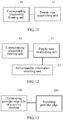
- a switching provider edge includes: A packet receiving unit 10 is configured to receive a label mapping message, where the label mapping message includes: information of a switching provider edge at a bifurcation position and information of at least two next hops or at least two outgoing interfaces of the switching provider edge at the bifurcation position.
- the switching provider edge at the bifurcation position here refers to a switching provider edge that implements redundancy protection of a pseudo wire. It may be that the switching provider edge is connected to two different TPE devices, and it may also be that the switching provider edge may reach the same next-hop device through different outgoing interfaces.
- the label mapping message may further include explicit path information that is used for releasing explicit routing information, and active/standby information indicating establishment of at least two pseudo wires, and so on.
- a parsing unit 11 is configured to parse the label mapping message received by the packet receiving unit 10 to obtain the information of the switching provider edge at the bifurcation position and the information of at least two next hops or at least two outgoing interfaces.
- the parsing unit 11 may specifically be a sub-TLV parsing unit, configured to parse explicit path information such as information of additional type Sub-TLV in TLV, in the label mapping message, to obtain the information of the switching provider edge at the bifurcation position and the information of at least two next hops or at least two outgoing interfaces of the switching provider edge.
- explicit path information such as information of additional type Sub-TLV in TLV, in the label mapping message
- a matching and establishing unit 12 is configured to compare the information of the switching provider edge at the bifurcation position with information of a local device, where the information of the switching provider edge at the bifurcation position is obtained through parsing by the parsing unit 11, and if the information of the switching provider edge at the bifurcation position matches with the information of the local device, establish at least two pseudo wires from the switching provider edge according to the information of at least two next hops or at least two outgoing interfaces.
- the switching provider edge at the bifurcation position matches with the information of the local device, where the information of the switching provider edge at the bifurcation position is obtained by the matching and establishing unit 12, it indicates that the switching provider edge is the switching provider edge at the bifurcation position.
- at least two pseudo wires are established from the switching provider edge according to the information of at least two next hops or at least two outgoing interfaces. Specifically, one pseudo wire is established between the switching provider edge and a TPE device that is corresponding to information of each next hop address, or a pseudo wire is established between the switching provider edge and a next-hop TPE device respectively through at least two outgoing interfaces.
- the label mapping message is forwarded to a next-hop node device to complete establishment of an MS-PW segment.
- one of the pseudo wires may be set as an active pseudo wire, and another pseudo wire may be set as a standby pseudo wire according to a preset policy. In this way, after the pseudo wires are established, when the switching provider edge at the bifurcation position determines that the active pseudo wire is faulty, a fast protection switchover of a pseudo wire may be completed directly.
- a switching provider edge may further include an information obtaining unit 13, configured to obtain active/standby relationship information for establishing at least two pseudo wires, and a matching and establishing unit 12 establishes a pseudo wire according to the active/standby relationship information obtained by the information obtaining unit 13.
- the information obtaining unit 13 may be a parsing sub-unit, configured to parse the label mapping message received by the packet receiving unit 10 to obtain active/standby relationship information of at least two pseudo wires, and may also be a notification receiving and parsing sub-unit, configured to receive an active/standby pseudo wire information notification sent by a TPE that is connected to a customer edge, and parse the active/standby pseudo wire information notification to obtain the active/standby relationship information of the at least two pseudo wires.
- a switching provider edge may further include: a failure switchover unit 14, configured to perform an active/standby pseudo wire switchover when it is determined that an active pseudo wire of the at least two pseudo wires that are established by the matching and establishing unit 12 is faulty.
- the packet receiving unit 10 receives the label mapping message sent by the TPE that is directly connected to the customer edge.
- the parsing unit 11 obtains the information of the switching provider edge at the bifurcation position and the information of at least two next hops or at least two outgoing interfaces of the switching provider edge through parsing. If the information of the switching provider edge at the bifurcation position matches with the information of the local device, the matching and establishing unit 12 establishes at least two pseudo wires from the switching provider edge according to the information of at least two next hops or at least two outgoing interfaces.
- the switching provider edge in this embodiment of the present invention establishes at least two pseudo wires, the TPE only needs to send one label mapping message to establish at least two pseudo wires.
- the switching provider edge in this embodiment establishes multiple pseudo wires from a local device to a destination node, and in this way, a resource consumed by pseudo wire establishment can be reduced.
- the switching provider edge at the bifurcation position establishes two pseudo wires, establishment of multiple MS-PW segments is completed, and an identification of an active/standby MS-PW segment may be implemented.
- a fast protection switchover of an MS-PW may be implemented on the switching provider edge. In this way, a fast recovery process of a pseudo wire is speeded up, and segment protection of the MS-PW may be provided from the switching provider edge at the bifurcation position, thereby making better use of a network resource.
- a terminating provider edge TPE of a service provider includes: A packet generating unit 20 is configured to generate a label mapping message, where the label mapping message includes: information of a switching provider edge at a bifurcation position and information of at least two next hops or at least two outgoing interfaces of the switching provider edge at the bifurcation position.
- the packet generating unit 20 may add additional information Sub-TLV to explicit path information TLV in the label mapping message, and add the information of the switching provider edge at the bifurcation position and the information of at least two next hops or at least two outgoing interfaces of the switching provider edge to an additional type Sub-TLV.
- a packet sending unit 21 sends the label mapping message generated by the packet generating unit 20 to a switching provider edge, so that a switching provider edge that matches with the information of the switching provider edge at the bifurcation position establishes at least two pseudo wires from the switching provider edge according to the information of two next hops or at least two outgoing interfaces.
- a TPE may further include: a notification sending unit 22, configured to send an active/standby pseudo wire information notification to a switching provider edge, so that a switching provider edge that matches with information of a switching provider edge at a bifurcation position also establishes at least two pseudo wires according to the active/standby pseudo wire information notification.
- a notification sending unit 22 configured to send an active/standby pseudo wire information notification to a switching provider edge, so that a switching provider edge that matches with information of a switching provider edge at a bifurcation position also establishes at least two pseudo wires according to the active/standby pseudo wire information notification.
- the packet generating unit 20 In the terminating provider edge TPE of the service provider in this embodiment, the packet generating unit 20 generates the label mapping message, where the label mapping message includes the information of the switching provider edge at the bifurcation position and the information of at least two next hops or at least two outgoing interfaces of the switching provider edge, and the packet sending unit 21 sends the label mapping message.
- the switching provider edge at the bifurcation position After receiving the label mapping message, the switching provider edge at the bifurcation position establishes at least two pseudo wires from the switching provider edge according to the information of at least two next hops or at least two outgoing interfaces.
- the TPE only needs to send one label mapping message to establish at least two pseudo wires, thereby reducing a resource consumed by pseudo wire establishment.
- one of the pseudo wires is an active pseudo wire. In this way, when the active pseudo wire is faulty, an active/standby pseudo wire switchover may be performed directly.
- a switching provider edge includes: A corresponding relationship forming unit 30 is configured to form pseudo wire routing entry information, where the pseudo wire routing entry information includes: a corresponding relationship between a first destination address and at least two next hop addresses, or information of at least two different routes to a device that is corresponding to the first destination address.
- the corresponding relationship forming unit 30 forms the pseudo wire routing entry information after receiving a route extension message and during a route information diffusion process of a TPE device.
- a pseudo wire establishing unit 31 is configured to, when receiving pseudo wire establishing signaling, where the pseudo wire establishing signaling requests that a pseudo wire to the device that is corresponding to the first destination address be established, establish at least two pseudo wires from a local device according to the at least two next hop addresses that are corresponding to the first destination address, or the information of at least two different routes to the device that is corresponding to the first destination address, where the at least two next hop addresses that are corresponding to the first destination address, or the information of at least two different routes to the device that is corresponding to the first destination address is formed by the corresponding relationship forming unit 30.
- a device in this embodiment may further include:
- the corresponding relationship forming unit 30 forms the pseudo wire routing entry information, where the pseudo wire routing entry information includes the corresponding relationship between the first destination address and the at least two next hop addresses, or the information of at least two different routes to the device that is corresponding to the first destination address.
- the pseudo wire establishing unit 31 establishes at least two pseudo wires from the local device according to the at least two next hop addresses, or the information of at least two different routes to the device that is corresponding to the first destination address.
- one of the pseudo wires is an active pseudo wire.
- the switching provider edge determines that the active pseudo wire is faulty, an active/standby pseudo wire switchover is directly performed, so that a recovery process of a pseudo wire is simplified, and a network resource can also be saved.
- a system for establishing a pseudo wire includes a switching provider edge 200 and a terminating provider edge TPE of a service provider 100, where:
- the method for establishing a pseudo wire in this embodiment of the present invention is applicable to pseudo wire establishment in an MS-PW system, and includes: receiving, by a switching provider edge, a label mapping message sent by a TPE that is directly connected to a customer edge, obtaining information of a switching provider edge at a bifurcation position and information of at least two next hops or at least two outgoing interfaces of the switching provider edge through parsing, and establishing at least two pseudo wires from the switching provider edge according to the information of at least two next hops or at least two outgoing interfaces.
- a TPE only needs to send one label mapping message to establish at least two pseudo wires.
- the switching provider edge at the bifurcation position establishes two pseudo wires, and completes establishment of multiple MS-PW segments, and furthermore, an identification of an active/standby MS-PW segment may be implemented.
- a fast protection switchover of an MS-PW may be implemented on the switching provider edge. In this way, a fast recovery process of a pseudo wire is speeded up, and segment protection of the MS-PW can be provided from the switching provider edge at the bifurcation position, thereby making better use of a network resource.
- the program may be stored in a computer readable storage medium, and the storage medium may include a Read Only Memory (ROM), a Random Access Memory (RAM), a magnetic disk, or an optical disk, and so on.
- ROM Read Only Memory
- RAM Random Access Memory
Landscapes
- Engineering & Computer Science (AREA)
- Computer Networks & Wireless Communication (AREA)
- Signal Processing (AREA)
- Data Exchanges In Wide-Area Networks (AREA)
Claims (4)
- Verfahren zum Einrichten von mindestens zwei Pseudodrähten, aufweisend:Empfangen (101) einer Label-Zuordnungs-Nachricht, wobei die Label-Zuordnungs-Nachricht aufweist: Informationen über einen Vermittlungs-Anbieter-Rand an einer Verzweigungsposition, Informationen über mindestens zwei ausgehende Schnittstellen des Vermittlungs-Anbieter-Randes an der Verzweigungsposition, und Informationen, die sich auf einen expliziten Pfad beziehen, wobei die Informationen, die sich auf den expliziten Pfad bezieht, verwendet werden, Aktiv-/Standby-Informationen freizugeben, die die Einrichtung von mindestens zwei Pseudodrähten anzeigen;Parsen (102) der Label-Zuordnungs-Nachricht, um die Informationen über den Vermittlungs-Anbieter-Rand an der Verzweigungsposition, die Informationen über mindestens zwei ausgehende Schnittstellen, und die expliziten Pfadinformationen zu erhalten; undVergleichen von Informationen über eine lokale Vorrichtung mit den Informationen über den Vermittlungs-Anbieter-Rand an der Verzweigungsposition, und wenn die Informationen über die lokale Vorrichtung mit den Informationen über den Vermittlungs-Anbieter-Rand an der Verzweigungsposition übereinstimmen, Einrichten (103) von mindestens zwei Pseudodrähten von dem Vermittlungs-Anbieter-Rand gemäß den Informationen über mindestens zwei ausgehende Schnittstellen, wobei einer der Pseudodrähte als ein aktiver Pseudodraht festgelegt wird und ein anderer Pseudodraht als ein Standby-Pseudodraht festgelegt wird,wobei vor dem Einrichten von mindestens zwei Pseudodrähten von dem Vermittlungs-Anbieter-Rand gemäß den Informationen von mindestens zwei ausgehenden Schnittstellen das Verfahren ferner aufweist:
Erhalten von Aktiv-/Standby-Beziehungsinformationen über mindestens zwei Pseudodrähte, und Einrichten von mindestens zwei Pseudodrähten gemäß den Aktiv-/Standby-Beziehungsinformationen. - Verfahren nach Anspruch 1, wobei das Erhalten der Aktiv-/Standby-Beziehungsinformationen über die mindestens zwei Pseudodrähte speziell aufweist:
Parsen der Label-Zuordnungs-Nachricht, um die Aktiv-/Standby-Beziehungsinformationen über die mindestens zwei Pseudodrähte zu erhalten; oder Empfangen einer Aktiv-/Standby-Pseudodraht-Informationsbenachrichtigung, die von einem abschließenden Anbieter-Rand, TPE, eines Dienstanbieters gesendet wird, und Parsen der Aktiv-/Standby-Pseudodraht-Informationsbenachrichtigung. - Vermittlungs-Anbieter-Rand (200), aufweisend:eine Paketempfangseinheit (10), die konfiguriert ist, um eine Label-Zuordnungs-Nachricht zu empfangen, wobei die Label-Zuordnungs-Nachricht aufweist: Informationen über einen Vermittlungs-Anbieter-Rand an einer Verzweigungsposition, Informationen über mindestens zwei ausgehende Schnittstellen des Vermittlungs-Anbieter-Randes an der Verzweigungsposition, und Informationen, die sich auf einen expliziten Pfad beziehen, wobei die Informationen, die sich auf den expliziten Pfad beziehen, verwendet werden, um Aktiv-/Standby-Informationen freizugeben, die die Einrichtung von mindestens zwei Pseudodrähten anzeigen;eine Parser-Einheit (11), die konfiguriert ist, um die von der Paketempfangseinheit empfangene Label-Zuordnungs-Nachricht zu parsen, um die Informationen über den Vermittlungs-Anbieter-Rand an der Verzweigungsposition, die Informationen über mindestens zwei Ausgangsschnittstellen, und die expliziten Pfadinformationen zu erhalten; undeine Abgleichs- und Einrichtungseinheit (12), die konfiguriert ist, um die Informationen über den Vermittlungs-Anbieter-Rand an den Verzweigungspositionen mit Informationen über eine lokale Vorrichtung zu vergleichen, wobei die Informationen über den Vermittlungs-Anbieter-Rand an der Verzweigungsposition durch die Parser-Einheit durch Parsen erhalten werden, und wenn die Informationen über den Vermittlungs-Anbieter-Rand an den Verzweigungspositionen mit den Informationen über die lokale Vorrichtung übereinstimmen, Einrichten von mindestens zwei Pseudodrähten von dem Vermittlungs-Anbieter-Rand gemäß den Informationen über die mindestens zwei ausgehenden Schnittstellen, wobei einer der Pseudodrähte als ein aktiver Pseudodraht festgelegt wird und ein anderer Pseudodraht als ein Standby-Pseudodraht festgelegt wird, ferner aufweisend:eine Informationserlangungseinheit (13), die konfiguriert ist, um Aktiv-/Standby-Beziehungsinformationen über die mindestens zwei Pseudodrähte zu erhalten, wobei die Abgleichs- und Einrichtungseinheit einen Pseudodraht gemäß den von der Informationserlangungseinheit erhaltenen Aktiv-/Standby-Beziehungsinformationen einrichtet.
- Abschluss-Anbieter-Rand, TPE, eines Dienstanbieters (100), aufweisend:eine Paketerzeugungseinheit, die konfiguriert ist, um eine Label-Zuordnungs-Nachricht zu erzeugen, wobei die Label-Zuordnungs-Nachricht aufweist:Informationen über einen Vermittlungs-Anbieter-Rand (200) an einer Verzweigungsposition, Informationen über mindestens zwei Ausgangsschnittstellen des Vermittlungs-Anbieter-Randes an der Verzweigungsposition, und Informationen,die sich auf einen expliziten Pfad beziehen, wobei die Informationen, die sich auf den expliziten Pfad beziehen, verwendet werden, um Aktiv-/Standby-Informationen freizugeben, die die Einrichtung von mindestens zwei Pseudodrähten anzeigen; undeine Paketsendeeinheit, die konfiguriert ist, um die von der Paketerzeugungseinheit erzeugte Label-Zuordnungs-Nachricht an einen Vermittlungs-Anbieter-Rand zu senden, so dass ein Vermittlungs-Anbieter-Rand, der mit den Informationen über den Vermittlungs-Anbieter-Rand an der Verzweigungspositionen übereinstimmt,mindestens zwei Pseudodrähte von dem Vermittlungs-Anbieter-Rand gemäß den Informationen über die mindestens zwei ausgehenden Schnittstellen einrichtet, ferner aufweisend:
eine Benachrichtigungs-Sendeeinheit, die konfiguriert ist, um eine Aktiv-/Standby-Pseudodraht-Informationsbenachrichtigung an den Vermittlungs-Anbieter-Rand zu senden, so dass der Vermittlungs-Anbieter-Rand, der mit den Informationen über den Vermittlungs-Anbieter-Rand an der Verzweigungspositionen übereinstimmt, auch die mindestens zwei Pseudodrähte gemäß der Aktiv-/Standby-Pseudodraht-Informationsbenachrichtigung einrichtet, wobei einer der Pseudodrähte als ein aktiver Pseudodraht festgelegt wird und ein anderer Pseudodraht als Standby-Pseudodraht festgelegt wird.
Applications Claiming Priority (3)
| Application Number | Priority Date | Filing Date | Title |
|---|---|---|---|
| CN201010001249.6A CN102130813B (zh) | 2010-01-15 | 2010-01-15 | 伪线建立方法、系统及设备 |
| PCT/CN2011/070308 WO2011085693A1 (zh) | 2010-01-15 | 2011-01-17 | 伪线建立方法、系统及设备 |
| EP11732683.5A EP2525536B1 (de) | 2010-01-15 | 2011-01-17 | Verfahren und vorrichtung zum aufbau von pseudoverdrahtungen |
Related Parent Applications (1)
| Application Number | Title | Priority Date | Filing Date |
|---|---|---|---|
| EP11732683.5A Division EP2525536B1 (de) | 2010-01-15 | 2011-01-17 | Verfahren und vorrichtung zum aufbau von pseudoverdrahtungen |
Publications (2)
| Publication Number | Publication Date |
|---|---|
| EP2963867A1 EP2963867A1 (de) | 2016-01-06 |
| EP2963867B1 true EP2963867B1 (de) | 2018-09-26 |
Family
ID=44268709
Family Applications (2)
| Application Number | Title | Priority Date | Filing Date |
|---|---|---|---|
| EP11732683.5A Not-in-force EP2525536B1 (de) | 2010-01-15 | 2011-01-17 | Verfahren und vorrichtung zum aufbau von pseudoverdrahtungen |
| EP15176388.5A Not-in-force EP2963867B1 (de) | 2010-01-15 | 2011-01-17 | Verfahren, system und vorrichtung zur herstellung von pseudodraht |
Family Applications Before (1)
| Application Number | Title | Priority Date | Filing Date |
|---|---|---|---|
| EP11732683.5A Not-in-force EP2525536B1 (de) | 2010-01-15 | 2011-01-17 | Verfahren und vorrichtung zum aufbau von pseudoverdrahtungen |
Country Status (5)
| Country | Link |
|---|---|
| US (3) | US9160655B2 (de) |
| EP (2) | EP2525536B1 (de) |
| JP (1) | JP5600182B2 (de) |
| CN (2) | CN102130813B (de) |
| WO (1) | WO2011085693A1 (de) |
Families Citing this family (11)
| Publication number | Priority date | Publication date | Assignee | Title |
|---|---|---|---|---|
| US8929249B2 (en) | 2010-09-03 | 2015-01-06 | Futurewei Technologies, Inc. | System and method for virtual private local area network service to use the flow aware pseudowire |
| CN102957611A (zh) * | 2011-08-25 | 2013-03-06 | 华为技术有限公司 | 建立p2mp ms-pw的方法、设备及系统 |
| CN102404199B (zh) * | 2011-10-11 | 2014-04-30 | 中兴通讯股份有限公司 | 一种多段伪线的建立及恢复方法、装置和系统 |
| CN102801630B (zh) * | 2012-08-23 | 2015-07-22 | 杭州华三通信技术有限公司 | 一种虚连接实现的方法和设备 |
| CN104579960B (zh) * | 2013-10-29 | 2018-12-21 | 中兴通讯股份有限公司 | 接口参数同步方法和装置 |
| CN104811324A (zh) * | 2014-01-24 | 2015-07-29 | 中兴通讯股份有限公司 | 伪线保护方法、装置及节点 |
| US9949000B1 (en) | 2015-03-17 | 2018-04-17 | 8X8, Inc. | IPBX control interface for distributed networks |
| CN104796288B (zh) * | 2015-04-08 | 2018-04-27 | 广东睿江云计算股份有限公司 | 任播通讯方法和装置 |
| CN107040392B (zh) * | 2015-07-29 | 2020-08-04 | 南京中兴软件有限责任公司 | 伪线双归保护管理方法及通信设备 |
| EP3836492B1 (de) * | 2016-09-30 | 2023-11-08 | Huawei Technologies Co., Ltd. | Verfahren und vorrichtung zum teilen von pseudo-drahtlasten |
| CN109981452B (zh) * | 2019-02-28 | 2021-03-23 | 新华三技术有限公司 | 一种pw链路的回切方法及装置 |
Family Cites Families (25)
| Publication number | Priority date | Publication date | Assignee | Title |
|---|---|---|---|---|
| JP3790658B2 (ja) * | 2000-03-27 | 2006-06-28 | 富士通株式会社 | ネットワークにおけるルーティング情報マッピング装置、その方法及び記録媒体 |
| US7230912B1 (en) * | 2001-06-14 | 2007-06-12 | Juniper Networks, Inc. | Sampling to a next hop |
| CN1625176B (zh) * | 2003-12-03 | 2010-04-28 | 华为技术有限公司 | 基于边缘到边缘伪线仿真协议的通信方法 |
| US7535856B2 (en) * | 2005-02-19 | 2009-05-19 | Cisco Technology, Inc. | Techniques for zero touch provisioning of edge nodes for a virtual private network |
| US7408941B2 (en) | 2005-06-14 | 2008-08-05 | Cisco Technology, Inc. | Method for auto-routing of multi-hop pseudowires |
| JP4509885B2 (ja) * | 2005-07-20 | 2010-07-21 | 富士通株式会社 | シグナリング装置 |
| CN1909501A (zh) | 2005-08-05 | 2007-02-07 | 华为技术有限公司 | 一种端到端业务快速收敛的方法和路由设备 |
| CN100531047C (zh) * | 2005-09-30 | 2009-08-19 | 华为技术有限公司 | 对包交换网络上的伪线进行保护倒换的方法 |
| US8588061B2 (en) * | 2005-10-07 | 2013-11-19 | Brixham Solutions Ltd. | Application wire |
| CN100433719C (zh) * | 2005-12-13 | 2008-11-12 | 华为技术有限公司 | 一种边缘到边缘伪线仿真多跳伪线的检验方法 |
| CN100499589C (zh) * | 2006-02-27 | 2009-06-10 | 华为技术有限公司 | 一种建立端到端伪线仿真的多跳伪线的方法 |
| CN100446472C (zh) | 2006-05-15 | 2008-12-24 | 华为技术有限公司 | 一种业务路由返回的方法 |
| US7782847B2 (en) * | 2006-10-19 | 2010-08-24 | Alcatel Lucent | Method and system for verifying connectivity of multi-segment pseudo-wires by tracing |
| CN100450039C (zh) | 2007-01-12 | 2009-01-07 | 华为技术有限公司 | 快速收敛端到端业务的方法和装置 |
| US8130775B2 (en) * | 2007-02-26 | 2012-03-06 | France Telecom | Mechanism for protecting a pseudo-wire |
| JP4686490B2 (ja) * | 2007-02-28 | 2011-05-25 | 日本電信電話株式会社 | パス切替方法、パス切替システムおよび分岐ノード |
| US7962717B2 (en) * | 2007-03-14 | 2011-06-14 | Xmos Limited | Message routing scheme |
| ATE479250T1 (de) * | 2007-04-17 | 2010-09-15 | Alcatel Lucent | Verfahren und vorrichtung zur reservierung von netzwerkressourcen für eine punkt-zu-punkt- pseudoverbindung |
| US7948900B2 (en) * | 2007-05-10 | 2011-05-24 | Alcatel Lucent | Method and system for verifying connectivity of multi-segment pseudo-wires |
| CN101159573A (zh) * | 2007-09-17 | 2008-04-09 | 杭州华三通信技术有限公司 | 一种利用任播技术实现负载分担的方法、设备及系统 |
| US8107386B2 (en) * | 2008-02-07 | 2012-01-31 | Cisco Technology, Inc. | VPLS N-PE redundancy using pseudo wire fast failover |
| CN101552711B (zh) * | 2008-04-03 | 2011-09-14 | 华为技术有限公司 | 建立伪线映射的方法及装置 |
| FR2930698A1 (fr) * | 2008-04-24 | 2009-10-30 | France Telecom | Mecanisme de mise a jour des parametres d'une session etablie au travers d'un circuit virtuel |
| US8724451B2 (en) * | 2008-06-27 | 2014-05-13 | France Telecom | Method for protecting a pseudo-wire |
| CN101505227B (zh) | 2009-03-11 | 2012-06-27 | 华为技术有限公司 | 一种实现点到多点伪线的方法、设备和系统 |
-
2010
- 2010-01-15 CN CN201010001249.6A patent/CN102130813B/zh not_active Expired - Fee Related
- 2010-01-15 CN CN201610182115.6A patent/CN105704029B/zh not_active Expired - Fee Related
-
2011
- 2011-01-17 WO PCT/CN2011/070308 patent/WO2011085693A1/zh not_active Ceased
- 2011-01-17 EP EP11732683.5A patent/EP2525536B1/de not_active Not-in-force
- 2011-01-17 EP EP15176388.5A patent/EP2963867B1/de not_active Not-in-force
- 2011-01-17 JP JP2012548331A patent/JP5600182B2/ja not_active Expired - Fee Related
-
2012
- 2012-07-13 US US13/548,880 patent/US9160655B2/en active Active
-
2015
- 2015-03-06 US US14/640,841 patent/US9391882B2/en not_active Expired - Fee Related
-
2016
- 2016-06-17 US US15/185,982 patent/US9912586B2/en not_active Expired - Fee Related
Non-Patent Citations (1)
| Title |
|---|
| None * |
Also Published As
| Publication number | Publication date |
|---|---|
| WO2011085693A1 (zh) | 2011-07-21 |
| EP2525536B1 (de) | 2015-07-15 |
| US9391882B2 (en) | 2016-07-12 |
| CN102130813B (zh) | 2016-08-03 |
| US9912586B2 (en) | 2018-03-06 |
| US20150188809A1 (en) | 2015-07-02 |
| JP5600182B2 (ja) | 2014-10-01 |
| US20120281702A1 (en) | 2012-11-08 |
| JP2013529398A (ja) | 2013-07-18 |
| CN105704029A (zh) | 2016-06-22 |
| CN105704029B (zh) | 2020-06-26 |
| US20160294690A1 (en) | 2016-10-06 |
| EP2525536A4 (de) | 2013-02-27 |
| CN102130813A (zh) | 2011-07-20 |
| US9160655B2 (en) | 2015-10-13 |
| EP2963867A1 (de) | 2016-01-06 |
| EP2525536A1 (de) | 2012-11-21 |
Similar Documents
| Publication | Publication Date | Title |
|---|---|---|
| EP2525536B1 (de) | Verfahren und vorrichtung zum aufbau von pseudoverdrahtungen | |
| EP3002913B1 (de) | Tunnelherstellungsverfahren, etikettenzuweisungsverfahren, vorrichtung und netzwerksystem | |
| CN108574630B (zh) | Evpn报文处理方法、设备及系统 | |
| US8953460B1 (en) | Network liveliness detection using session-external communications | |
| EP3148131B1 (de) | Verfahren und vorrichtung zur veröffentlichung von adresseninformationen | |
| WO2014194749A1 (zh) | 边缘设备的vpn实现处理方法及装置 | |
| US10560456B2 (en) | Method, apparatus, and system for collecting access control list | |
| CN107968750A (zh) | 报文传输方法、装置及节点 | |
| WO2019201014A1 (zh) | 以太网段标识邻接检测处理方法及装置、存储介质 | |
| US20150131672A1 (en) | Method, device and system for establishing a pseudo wire | |
| US20170195214A1 (en) | ISIS-Based Routing Calculation Method And Device | |
| CN104168194A (zh) | 集群网络路径控制方法、设备和集群网络系统 | |
| CN105227458A (zh) | Trill isis的路由计算方法及装置 | |
| JP6371399B2 (ja) | インターフェースパラメーター同期方法及び装置 | |
| WO2020244304A1 (zh) | 路由信息发送的方法、路由选路的方法和装置 | |
| WO2013026399A1 (zh) | 建立p2mp ms-pw的方法、设备及系统 | |
| CN102377637B (zh) | 多段伪线共享带宽的方法及系统、提供商边缘节点 | |
| CN117014356A (zh) | 路由通告消息的处理方法、装置、存储介质及电子装置 | |
| CN102377637A (zh) | 多段伪线共享带宽的方法及系统、提供商边缘节点 |
Legal Events
| Date | Code | Title | Description |
|---|---|---|---|
| PUAI | Public reference made under article 153(3) epc to a published international application that has entered the european phase |
Free format text: ORIGINAL CODE: 0009012 |
|
| AC | Divisional application: reference to earlier application |
Ref document number: 2525536 Country of ref document: EP Kind code of ref document: P |
|
| AK | Designated contracting states |
Kind code of ref document: A1 Designated state(s): AL AT BE BG CH CY CZ DE DK EE ES FI FR GB GR HR HU IE IS IT LI LT LU LV MC MK MT NL NO PL PT RO RS SE SI SK SM TR |
|
| 17P | Request for examination filed |
Effective date: 20160701 |
|
| RBV | Designated contracting states (corrected) |
Designated state(s): AL AT BE BG CH CY CZ DE DK EE ES FI FR GB GR HR HU IE IS IT LI LT LU LV MC MK MT NL NO PL PT RO RS SE SI SK SM TR |
|
| STAA | Information on the status of an ep patent application or granted ep patent |
Free format text: STATUS: EXAMINATION IS IN PROGRESS |
|
| 17Q | First examination report despatched |
Effective date: 20170216 |
|
| GRAP | Despatch of communication of intention to grant a patent |
Free format text: ORIGINAL CODE: EPIDOSNIGR1 |
|
| STAA | Information on the status of an ep patent application or granted ep patent |
Free format text: STATUS: GRANT OF PATENT IS INTENDED |
|
| INTG | Intention to grant announced |
Effective date: 20180426 |
|
| RIN1 | Information on inventor provided before grant (corrected) |
Inventor name: CAO, WEI Inventor name: XUE, LI Inventor name: QIU, CHAOWA Inventor name: LIU, CHANGBAO |
|
| GRAS | Grant fee paid |
Free format text: ORIGINAL CODE: EPIDOSNIGR3 |
|
| GRAA | (expected) grant |
Free format text: ORIGINAL CODE: 0009210 |
|
| STAA | Information on the status of an ep patent application or granted ep patent |
Free format text: STATUS: THE PATENT HAS BEEN GRANTED |
|
| AC | Divisional application: reference to earlier application |
Ref document number: 2525536 Country of ref document: EP Kind code of ref document: P |
|
| AK | Designated contracting states |
Kind code of ref document: B1 Designated state(s): AL AT BE BG CH CY CZ DE DK EE ES FI FR GB GR HR HU IE IS IT LI LT LU LV MC MK MT NL NO PL PT RO RS SE SI SK SM TR |
|
| REG | Reference to a national code |
Ref country code: GB Ref legal event code: FG4D |
|
| REG | Reference to a national code |
Ref country code: CH Ref legal event code: EP |
|
| REG | Reference to a national code |
Ref country code: AT Ref legal event code: REF Ref document number: 1047339 Country of ref document: AT Kind code of ref document: T Effective date: 20181015 |
|
| REG | Reference to a national code |
Ref country code: IE Ref legal event code: FG4D |
|
| REG | Reference to a national code |
Ref country code: DE Ref legal event code: R096 Ref document number: 602011052467 Country of ref document: DE |
|
| REG | Reference to a national code |
Ref country code: NL Ref legal event code: MP Effective date: 20180926 |
|
| PG25 | Lapsed in a contracting state [announced via postgrant information from national office to epo] |
Ref country code: BG Free format text: LAPSE BECAUSE OF FAILURE TO SUBMIT A TRANSLATION OF THE DESCRIPTION OR TO PAY THE FEE WITHIN THE PRESCRIBED TIME-LIMIT Effective date: 20181226 Ref country code: GR Free format text: LAPSE BECAUSE OF FAILURE TO SUBMIT A TRANSLATION OF THE DESCRIPTION OR TO PAY THE FEE WITHIN THE PRESCRIBED TIME-LIMIT Effective date: 20181227 Ref country code: NO Free format text: LAPSE BECAUSE OF FAILURE TO SUBMIT A TRANSLATION OF THE DESCRIPTION OR TO PAY THE FEE WITHIN THE PRESCRIBED TIME-LIMIT Effective date: 20181226 Ref country code: LT Free format text: LAPSE BECAUSE OF FAILURE TO SUBMIT A TRANSLATION OF THE DESCRIPTION OR TO PAY THE FEE WITHIN THE PRESCRIBED TIME-LIMIT Effective date: 20180926 Ref country code: RS Free format text: LAPSE BECAUSE OF FAILURE TO SUBMIT A TRANSLATION OF THE DESCRIPTION OR TO PAY THE FEE WITHIN THE PRESCRIBED TIME-LIMIT Effective date: 20180926 Ref country code: FI Free format text: LAPSE BECAUSE OF FAILURE TO SUBMIT A TRANSLATION OF THE DESCRIPTION OR TO PAY THE FEE WITHIN THE PRESCRIBED TIME-LIMIT Effective date: 20180926 Ref country code: SE Free format text: LAPSE BECAUSE OF FAILURE TO SUBMIT A TRANSLATION OF THE DESCRIPTION OR TO PAY THE FEE WITHIN THE PRESCRIBED TIME-LIMIT Effective date: 20180926 |
|
| REG | Reference to a national code |
Ref country code: LT Ref legal event code: MG4D |
|
| PG25 | Lapsed in a contracting state [announced via postgrant information from national office to epo] |
Ref country code: LV Free format text: LAPSE BECAUSE OF FAILURE TO SUBMIT A TRANSLATION OF THE DESCRIPTION OR TO PAY THE FEE WITHIN THE PRESCRIBED TIME-LIMIT Effective date: 20180926 Ref country code: AL Free format text: LAPSE BECAUSE OF FAILURE TO SUBMIT A TRANSLATION OF THE DESCRIPTION OR TO PAY THE FEE WITHIN THE PRESCRIBED TIME-LIMIT Effective date: 20180926 Ref country code: HR Free format text: LAPSE BECAUSE OF FAILURE TO SUBMIT A TRANSLATION OF THE DESCRIPTION OR TO PAY THE FEE WITHIN THE PRESCRIBED TIME-LIMIT Effective date: 20180926 |
|
| REG | Reference to a national code |
Ref country code: AT Ref legal event code: MK05 Ref document number: 1047339 Country of ref document: AT Kind code of ref document: T Effective date: 20180926 |
|
| PG25 | Lapsed in a contracting state [announced via postgrant information from national office to epo] |
Ref country code: EE Free format text: LAPSE BECAUSE OF FAILURE TO SUBMIT A TRANSLATION OF THE DESCRIPTION OR TO PAY THE FEE WITHIN THE PRESCRIBED TIME-LIMIT Effective date: 20180926 Ref country code: IT Free format text: LAPSE BECAUSE OF FAILURE TO SUBMIT A TRANSLATION OF THE DESCRIPTION OR TO PAY THE FEE WITHIN THE PRESCRIBED TIME-LIMIT Effective date: 20180926 Ref country code: PL Free format text: LAPSE BECAUSE OF FAILURE TO SUBMIT A TRANSLATION OF THE DESCRIPTION OR TO PAY THE FEE WITHIN THE PRESCRIBED TIME-LIMIT Effective date: 20180926 Ref country code: CZ Free format text: LAPSE BECAUSE OF FAILURE TO SUBMIT A TRANSLATION OF THE DESCRIPTION OR TO PAY THE FEE WITHIN THE PRESCRIBED TIME-LIMIT Effective date: 20180926 Ref country code: RO Free format text: LAPSE BECAUSE OF FAILURE TO SUBMIT A TRANSLATION OF THE DESCRIPTION OR TO PAY THE FEE WITHIN THE PRESCRIBED TIME-LIMIT Effective date: 20180926 Ref country code: NL Free format text: LAPSE BECAUSE OF FAILURE TO SUBMIT A TRANSLATION OF THE DESCRIPTION OR TO PAY THE FEE WITHIN THE PRESCRIBED TIME-LIMIT Effective date: 20180926 Ref country code: ES Free format text: LAPSE BECAUSE OF FAILURE TO SUBMIT A TRANSLATION OF THE DESCRIPTION OR TO PAY THE FEE WITHIN THE PRESCRIBED TIME-LIMIT Effective date: 20180926 Ref country code: AT Free format text: LAPSE BECAUSE OF FAILURE TO SUBMIT A TRANSLATION OF THE DESCRIPTION OR TO PAY THE FEE WITHIN THE PRESCRIBED TIME-LIMIT Effective date: 20180926 Ref country code: IS Free format text: LAPSE BECAUSE OF FAILURE TO SUBMIT A TRANSLATION OF THE DESCRIPTION OR TO PAY THE FEE WITHIN THE PRESCRIBED TIME-LIMIT Effective date: 20190126 |
|
| PG25 | Lapsed in a contracting state [announced via postgrant information from national office to epo] |
Ref country code: SK Free format text: LAPSE BECAUSE OF FAILURE TO SUBMIT A TRANSLATION OF THE DESCRIPTION OR TO PAY THE FEE WITHIN THE PRESCRIBED TIME-LIMIT Effective date: 20180926 Ref country code: PT Free format text: LAPSE BECAUSE OF FAILURE TO SUBMIT A TRANSLATION OF THE DESCRIPTION OR TO PAY THE FEE WITHIN THE PRESCRIBED TIME-LIMIT Effective date: 20190126 Ref country code: SM Free format text: LAPSE BECAUSE OF FAILURE TO SUBMIT A TRANSLATION OF THE DESCRIPTION OR TO PAY THE FEE WITHIN THE PRESCRIBED TIME-LIMIT Effective date: 20180926 |
|
| REG | Reference to a national code |
Ref country code: DE Ref legal event code: R097 Ref document number: 602011052467 Country of ref document: DE |
|
| PG25 | Lapsed in a contracting state [announced via postgrant information from national office to epo] |
Ref country code: DK Free format text: LAPSE BECAUSE OF FAILURE TO SUBMIT A TRANSLATION OF THE DESCRIPTION OR TO PAY THE FEE WITHIN THE PRESCRIBED TIME-LIMIT Effective date: 20180926 |
|
| PLBE | No opposition filed within time limit |
Free format text: ORIGINAL CODE: 0009261 |
|
| STAA | Information on the status of an ep patent application or granted ep patent |
Free format text: STATUS: NO OPPOSITION FILED WITHIN TIME LIMIT |
|
| PG25 | Lapsed in a contracting state [announced via postgrant information from national office to epo] |
Ref country code: MC Free format text: LAPSE BECAUSE OF FAILURE TO SUBMIT A TRANSLATION OF THE DESCRIPTION OR TO PAY THE FEE WITHIN THE PRESCRIBED TIME-LIMIT Effective date: 20180926 |
|
| REG | Reference to a national code |
Ref country code: CH Ref legal event code: PL |
|
| 26N | No opposition filed |
Effective date: 20190627 |
|
| PG25 | Lapsed in a contracting state [announced via postgrant information from national office to epo] |
Ref country code: LU Free format text: LAPSE BECAUSE OF NON-PAYMENT OF DUE FEES Effective date: 20190117 |
|
| REG | Reference to a national code |
Ref country code: BE Ref legal event code: MM Effective date: 20190131 |
|
| REG | Reference to a national code |
Ref country code: IE Ref legal event code: MM4A |
|
| PG25 | Lapsed in a contracting state [announced via postgrant information from national office to epo] |
Ref country code: SI Free format text: LAPSE BECAUSE OF FAILURE TO SUBMIT A TRANSLATION OF THE DESCRIPTION OR TO PAY THE FEE WITHIN THE PRESCRIBED TIME-LIMIT Effective date: 20180926 |
|
| PG25 | Lapsed in a contracting state [announced via postgrant information from national office to epo] |
Ref country code: BE Free format text: LAPSE BECAUSE OF NON-PAYMENT OF DUE FEES Effective date: 20190131 |
|
| PG25 | Lapsed in a contracting state [announced via postgrant information from national office to epo] |
Ref country code: CH Free format text: LAPSE BECAUSE OF NON-PAYMENT OF DUE FEES Effective date: 20190131 Ref country code: LI Free format text: LAPSE BECAUSE OF NON-PAYMENT OF DUE FEES Effective date: 20190131 |
|
| PG25 | Lapsed in a contracting state [announced via postgrant information from national office to epo] |
Ref country code: IE Free format text: LAPSE BECAUSE OF NON-PAYMENT OF DUE FEES Effective date: 20190117 |
|
| PG25 | Lapsed in a contracting state [announced via postgrant information from national office to epo] |
Ref country code: TR Free format text: LAPSE BECAUSE OF FAILURE TO SUBMIT A TRANSLATION OF THE DESCRIPTION OR TO PAY THE FEE WITHIN THE PRESCRIBED TIME-LIMIT Effective date: 20180926 |
|
| PG25 | Lapsed in a contracting state [announced via postgrant information from national office to epo] |
Ref country code: MT Free format text: LAPSE BECAUSE OF NON-PAYMENT OF DUE FEES Effective date: 20190117 |
|
| PG25 | Lapsed in a contracting state [announced via postgrant information from national office to epo] |
Ref country code: CY Free format text: LAPSE BECAUSE OF FAILURE TO SUBMIT A TRANSLATION OF THE DESCRIPTION OR TO PAY THE FEE WITHIN THE PRESCRIBED TIME-LIMIT Effective date: 20180926 |
|
| PG25 | Lapsed in a contracting state [announced via postgrant information from national office to epo] |
Ref country code: HU Free format text: LAPSE BECAUSE OF FAILURE TO SUBMIT A TRANSLATION OF THE DESCRIPTION OR TO PAY THE FEE WITHIN THE PRESCRIBED TIME-LIMIT; INVALID AB INITIO Effective date: 20110117 |
|
| REG | Reference to a national code |
Ref country code: DE Ref legal event code: R079 Ref document number: 602011052467 Country of ref document: DE Free format text: PREVIOUS MAIN CLASS: H04L0012703000 Ipc: H04L0045280000 |
|
| PG25 | Lapsed in a contracting state [announced via postgrant information from national office to epo] |
Ref country code: MK Free format text: LAPSE BECAUSE OF FAILURE TO SUBMIT A TRANSLATION OF THE DESCRIPTION OR TO PAY THE FEE WITHIN THE PRESCRIBED TIME-LIMIT Effective date: 20180926 |
|
| REG | Reference to a national code |
Ref country code: FR Ref legal event code: PLFP Year of fee payment: 13 |
|
| PGFP | Annual fee paid to national office [announced via postgrant information from national office to epo] |
Ref country code: GB Payment date: 20221201 Year of fee payment: 13 Ref country code: FR Payment date: 20221208 Year of fee payment: 13 |
|
| PGFP | Annual fee paid to national office [announced via postgrant information from national office to epo] |
Ref country code: DE Payment date: 20221130 Year of fee payment: 13 |
|
| REG | Reference to a national code |
Ref country code: DE Ref legal event code: R119 Ref document number: 602011052467 Country of ref document: DE |
|
| GBPC | Gb: european patent ceased through non-payment of renewal fee |
Effective date: 20240117 |
|
| PG25 | Lapsed in a contracting state [announced via postgrant information from national office to epo] |
Ref country code: DE Free format text: LAPSE BECAUSE OF NON-PAYMENT OF DUE FEES Effective date: 20240801 |
|
| PG25 | Lapsed in a contracting state [announced via postgrant information from national office to epo] |
Ref country code: GB Free format text: LAPSE BECAUSE OF NON-PAYMENT OF DUE FEES Effective date: 20240117 |
|
| PG25 | Lapsed in a contracting state [announced via postgrant information from national office to epo] |
Ref country code: FR Free format text: LAPSE BECAUSE OF NON-PAYMENT OF DUE FEES Effective date: 20240131 |
|
| PG25 | Lapsed in a contracting state [announced via postgrant information from national office to epo] |
Ref country code: GB Free format text: LAPSE BECAUSE OF NON-PAYMENT OF DUE FEES Effective date: 20240117 Ref country code: FR Free format text: LAPSE BECAUSE OF NON-PAYMENT OF DUE FEES Effective date: 20240131 Ref country code: DE Free format text: LAPSE BECAUSE OF NON-PAYMENT OF DUE FEES Effective date: 20240801 |