EP2963750B1 - Deckelteil für elektrisches installationsmaterial - Google Patents
Deckelteil für elektrisches installationsmaterial Download PDFInfo
- Publication number
- EP2963750B1 EP2963750B1 EP15174106.3A EP15174106A EP2963750B1 EP 2963750 B1 EP2963750 B1 EP 2963750B1 EP 15174106 A EP15174106 A EP 15174106A EP 2963750 B1 EP2963750 B1 EP 2963750B1
- Authority
- EP
- European Patent Office
- Prior art keywords
- decorative frame
- cover part
- positioning
- frame
- base frame
- Prior art date
- Legal status (The legal status is an assumption and is not a legal conclusion. Google has not performed a legal analysis and makes no representation as to the accuracy of the status listed.)
- Active
Links
Images


Classifications
-
- H—ELECTRICITY
- H02—GENERATION; CONVERSION OR DISTRIBUTION OF ELECTRIC POWER
- H02G—INSTALLATION OF ELECTRIC CABLES OR LINES, OR OF COMBINED OPTICAL AND ELECTRIC CABLES OR LINES
- H02G3/00—Installations of electric cables or lines or protective tubing therefor in or on buildings, equivalent structures or vehicles
- H02G3/02—Details
- H02G3/08—Distribution boxes; Connection or junction boxes
- H02G3/14—Fastening of cover or lid to box
Definitions
- the present invention relates to a cover part for electrical installation material such as a switch, a power outlet, a push button, a dimmer or a wall socket. More particularly the invention relates to a cover frame manufactured from a material showing after-shrinkage behaviour.
- cover parts in particular cover frames for installation material such as, for example, switches, push buttons, dimmers or wall sockets, from synthetic material such as plastic, for example by injection moulding or by compression moulding.
- a drawback of particular synthetic or plastic materials is that they show after-shrinkage behaviour. With after-shrinkage behaviour is meant that, after manufacturing cover parts from such materials, the cover parts deform because they shrink.
- cover part 1 consists of a decorative frame 2 and a base frame 3, as illustrated in Figure 1 , because a result of after-shrinkage behaviour is that, for cover parts manufactured from these particular materials, the outer circumference 4 of the base frame 3 cannot be used to position on the edges 5 of the decorative frame 2, because then the decorative frame 2 would burst, crack or break. Examples of such cover parts are described in the documents WO2013/ 182819 and EP2194626 .
- a cover part is provided for electrical installation material, such as for example a switch, a push button, a dimmer or a wall socket.
- the cover part more in particular cover frame, comprises a decorative frame and a base frame which are each provided with a hole for providing a function.
- the decorative frame is made from a material showing after-shrinkage behaviour.
- a space is provided between an inner edge of the decorative frame and an outer edge of the base frame.
- the size of the decorative frame and the size of the base frame are such that, when they are put together, a space is present in between an inner edge of the decorative frame and an outer edge of the base frame.
- one of the decorative frame and the base frame is provided with positioning protrusions, such as for example positioning ribs or positioning studs, and the other of the decorative frame and the base frame is provided with positioning slots into which the positioning protrusions fit.
- the space that is provided in between the inner edge of the decorative frame and the outer edge of the base frame needs to be able to compensate for the changes in dimensions of the decorative frame as a result of the after-shrinkage behaviour of the material the decorative frame is made of.
- B S being the space
- B the width of the decorative frame
- ⁇ B the difference in width of the decorative frame due to after-shrinkage behaviour
- k PM % the post-mould shrinkage percentage of the material from which the decorative frame is made.
- ⁇ B may be between 0.1% and 1.5% of the width of the decorative frame, preferably be between 0.1% and 1%, and still more preferably between 0.1 and 0.5%.
- Providing the positioning protrusions and the positioning slots ensures that the centres of the decorative frame and the base frame are always perfectly aligned, so that bursting or cracking of the decorative frame can be prevented when the decorative frame shrinks because of after-shrinkage behaviour of the material the decorative frame is made of.
- the base frame By providing sufficient space to compensate for after-shrinkage behaviour and by providing the decorative frame and base frame with positioning means, i.e. positioning protrusions on the decorative frame and positioning slots in the base frame or vice versa, the base frame remains positioned centrally in the decorative frame irrespective of the changes due to the after-shrinkage behaviour, so that the holes for providing a function in the decorative frame and base frame are positioned perfectly with respect to each other. This results in a perfectly and safely functioning function and therefore perfectly and safely functioning installation material.
- positioning means i.e. positioning protrusions on the decorative frame and positioning slots in the base frame or vice versa
- the positioning protrusions and the positioning slots may be provided on axes of the decorative frame and the base frame, which axes intersect in the centre of the decorative frame and the base frame.
- these axes may be the central axes of the decorative frame and the base frame.
- these axes may be the diagonal axes of the decorative frame and the base frame.
- the axes may be any axes of the decorative frame and the base frame, as long as these axes intersect in the centre of the decorative frame and the base frame.
- the positioning slots may be oriented in the direction of the axes of the decorative frame or the base frame. In other words, the longitudinal direction of the positioning slots may coincide with the axes of the decorative frame or the base frame.
- the positioning protrusions and the positioning slots may be provided in the middle of the sides of the decorative frame and the base frame. According to other embodiments, the positioning protrusions and the positioning slots may be provided in the corners of the decorative frame and the base frame. According to still other embodiments, the positioning protrusions and the positioning slots may be provided on any location along a side of the decorative frame and the base frame, as long as these positioning protrusions and positioning slots are located on axes of the decorative frame and the base frame which intersect in the centres of the decorative frame and the base frame.
- Embodiments of the present invention may be implemented in cases where the cover part is a single cover part or a multiple, such as for example but not limited to a double or triple, cover part.
- Embodiments of the invention may in particular be advantageous when the decorative frame is made from a brittle material.
- brittle material is meant a material which bursts, breaks or cracks without having to exert too much forces thereon.
- the decorative frame may be made from a thermosetting material such as for example bakelite (phenol formaldehyde) or urea-formaldehyde.
- the present invention provides a cover part for electrical installation material.
- the cover part comprises a decorative frame and a base frame which are each provided with a hole for providing a function.
- the decorative frame is made from a material showing after-shrinkage behaviour.
- a space is provided between an inner edge of the decorative frame and an outer edge of the base frame, or in other words that the size of the decorative frame and the size of the base frame are such that when they are put together, a space exists between the inner edge of the decorative frame and the outer edge of the base frame.
- a cover part according to embodiments of the invention is further characterised in that one of the decorative frame and the base frame is provided with positioning protrusions fitting into positioning slots provided in the other of the decorative frame and the base frame.
- the base frame is positioned centrally in the decorative frame, even after shrinking, so that the holes in the decorative frame and the base frame for providing a function are perfectly aligned with respect to each other such that a function can be provided and work smoothly. This results in a perfectly and safely functioning function and therefore perfectly and safely functioning installation material.
- Figure 2 illustrates a first embodiment of a cover part 10 according to the invention.
- the cover part 10 according to this embodiment is a single cover part and comprises a decorative frame 11 and a base frame 12.
- the upper part of Figure 2 illustrates the cover part 10 as a whole as seen from the back side, that is, the cover part 10 with the decorative frame 11 being fixed, for example clicked, onto the base frame 12, such as during use, while the lower part of Figure 2 illustrates the decorative frame 11 and the base frame 12 separately from each other.
- the decorative frame 11 is made from a material showing after-shrinkage behaviour, such as for example a thermosetting material such as phenol formaldehyde (bakelite) or urea-formaldehyde.
- after-shrinkage behaviour is meant that, after manufacturing of the decorative frame 11 and during use, the material shrinks as a result of the continuation of chemical processes which have not yet ceased completely after manufacturing. This will cause the decorative frame to deform, so that, if no precautions are taken, the centres M of the decorative frame 11 and the base frame 12 are no longer positioned in perfect alignment with respect to each other. This makes the provision of the function more difficult and may lead to situations where the function does not function properly and may even lead to unsafe situations.
- a space S is provided in between an inner edge 14 of the decorative frame 11 and an outer edge 15 of the base frame 12.
- the space S that is provided needs to be such that is able to compensate for the changes in dimensions of the decorative frame as a result of the after-shrinkage behaviour.
- ⁇ B the difference in width of the decorative frame 11 due to after-shrinkage behaviour and k PM % the post-mould shrinkage percentage of the material from which the decorative frame 11 is made.
- ⁇ B may be between 0.1 % and 1.5% of the width of the decorative frame 11, preferably be between 0.1% and 1%, and still more preferably between 0.1 and 0.5%. This is schematically illustrated in Figure 3 .
- positioning means 16, 17 are provided as well. According to the present embodiment, on the inside of the decorative frame 11, positioning protrusions 16 are provided and, in the base frame 12, positioning slots 17 are provided.
- the positioning protrusions are designed as positioning ribs 16 which are provided on the inner edge 14 of the decorative frame 11.
- the positioning ribs 16 may be fixedly provided on the inner edge 14 and the bottom 18 of the decorative frame 11. This may, for example, be achieved by providing the decorative frame 11 and the positioning ribs 16 as a whole, in other words, in one piece, or by fixing the positioning ribs 16 to the inner edge 14 and the bottom 18 by, for example, gluing.
- An advantage thereof is that, with the smallest possible positioning ribs 16, still a greatest possible strength is achieved. The smaller the positioning ribs 16 are, the smaller the chance that the positioning ribs 16 can be seen on the front side of the decorative frame 11.
- the positioning slots 17 in the base frame 11 are formed such that the positioning ribs 16 of the decorative frame 11 fit into them.
- the positioning slots 17 are slightly larger than the positioning ribs 16.
- the positioning ribs 16 and the positioning slots 17 are provided on axes X,Y of respectively the decorative frame 11 and the base frame 12 which intersect in the centre M, and in the middle of the outer sides of respectively the decorative frame 11 and the base frame 12.
- the positioning ribs 16 and the positioning slots 17 are provided on the central axes X,Y of respectively the decorative frame 11 and the base frame 12. These central axes X,Y intersect in the centre M, as illustrated in the upper part of Figure 2 .
- the positioning slots 17 are oriented in the direction of the central axes X,Y. As can be seen in the Figure, always two positioning protrusions 16 are provided on each axis of the decorative frame 11 and two positioning slots 17 on each axis of the base frame 12. In other words, the longitudinal direction of the positioning slots 17 is situated along the central axes X,Y.
- the positioning ribs 16 have a centring function in one direction and are free in the other direction. Because such positioning ribs 16 are provided both on the central X axis and on the central Y axis, the decorative frame 11, and therefore also the hole 13a for the function, remains positioned with respect to the base frame 12 such that the function can easily be provided, and can also function perfectly after placement.
- Figure 4 illustrates a further embodiment in which the cover part 10 is a double cover part 10.
- the upper part of the Figure shows the cover part 10 as a whole as seen from the back side, that is, the cover part 10 with the decorative frame 11 being fixed, for example clicked, onto the base frame 12, such as during use, while the lower part of Figure 4 illustrates the decorative frame 11 and the base frame 12 separately from each other.
- ⁇ B the difference in width of the decorative frame 11 due to after-shrinkage behaviour and k PM % the post-mould shrinkage percentage of the material from which the decorative frame 11 is made.
- ⁇ B may be between 0.1 % and 1.5% of the width of the decorative frame 11, preferably be between 0.1% and 1%, and still more preferably between 0.1 and 0.5%.
- positioning protrusions 16 are provided on the inner edge 14 of the decorative frame 11 and positioning slots 17 in the base frame 12.
- the positioning protrusions are designed as positioning ribs 16 and the positioning slots 17 are placed and formed such that the positioning ribs 16 fit therein.
- the positioning ribs 16 and positioning slots 17 are provided on the central axes X,Y of respectively the decorative frame 11 and the base frame 12, which central axes X,Y intersect in the centre M, and in the middle of the outer sides of respectively the decorative frame 11 and the base frame 12.
- two positioning protrusions 16 are provided on each axis X of the decorative frame 11 and two positioning slots 17 on each axis Y of the base frame 12.
- Figure 5 shows a triple cover part 10 according to a further embodiment according to the invention.
- the positioning protrusions 16 are designed as positioning ribs 16 and the positioning ribs 16 and the positioning slots 17 are provided on the central axes X,Y and in the middle of the outer sides of respectively the decorative frame 11 and the base frame 12.
- FIG. 6 shows a further embodiment according to the invention.
- the cover part 10 is a triple cover part.
- the positioning protrusions 16 are here designed as positioning studs.
- the positioning studs 16 and the positioning slots 17 are placed along the central axes X,Y of respectively the decorative frame 11 and the base frame 12. Similar to what was described for the above embodiments, here as well, always two positioning protrusions 16 are provided on each axis X of the decorative frame 11 and two positioning slots 17 are provided on each axis Y of the base frame 12.
- the positioning studs 16 and positioning slots 17 are provided in the middle of the width B of the outer side of the decorative frame 11 and the base frame 12, in the longitudinal direction L they are not provided on the outer side, but between the first and second and between the second and third hole 13a for the function.
- the positioning slots 17 are oriented according to the direction of the central axes X,Y.
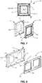
- Figure 7 shows a still further embodiment according to the invention.
- the cover part 10 is a single cover part.
- the positioning protrusions 16 are designed as positioning studs.
- the positioning studs 16 are fixed to the bottom 18 of the decorative frame 11.
- the positioning studs 16 and the positioning slots 17 are provided in the corners of the cover part 10, and are therefore located on the diagonal axes X,Y of respectively the decorative frame 11 and the base frame 12.
- the positioning slots 17 are oriented according to the direction of the diagonal axes X,Y of the base frame 12.
- two positioning protrusions 16 are provided on each axis X of the decorative frame 11 and two positioning slots 17 on each axis Y of the base frame 12.
- FIG 8 shows a still further embodiment according to the invention.
- the cover part 10 is a double cover part.
- the positioning protrusions 16 are designed as positioning studs.
- the positioning studs 16 and positioning slots 17 are provided on axes X,Y of respectively the decorative frame 11 and base frame 12 which intersect in the centre M of respectively the decorative frame 11 and the base frame 12.
- the axes X,Y are not the central axes like in Figures 2 and 4 to 6 and not the diagonal axes like in Figure 7 .
- the positioning studs 16 and positioning slots 17 may be placed randomly along the width sides B of respectively the decorative frame 11 and the base frame 12.
- positioning studs 16 and positioning slots 17 may just as well be placed along the longitudinal sides L (not illustrated) instead of along the width sides B as illustrated in Figure 8 , as long as they are located on axes X,Y of respectively the decorative frame 11 and the base frame 12 which intersect in the centre M of the decorative frame 11 and the base frame 12.
- the positioning protrusions 16 are always provided on the decorative frame 11 and the positioning slots 17 always in the base frame 12, a skilled person will understand that this may just as well be the other way round. According to certain embodiments, the positioning slots 17 may be provided in the decorative frame 11 and the positioning protrusions 16 may be provided in the base frame 12.
- the positioning slots 17 may be oriented such that the axis of each of the positioning slots 17 goes through the centre M of the base frame 12, but that therefore two positioning slots 17 are not necessarily on the same axis.
- the axes of the positioning slots 17 do not always need to coincide with diagonal axes or central axes of the base frame 12 either. As long as the positioning slots 17 are oriented according to an axis going through the centre M of the base frame 12, the advantages of the invention are achieved and these embodiments fall within the scope of the invention.
Landscapes
- Engineering & Computer Science (AREA)
- Architecture (AREA)
- Civil Engineering (AREA)
- Structural Engineering (AREA)
- Casings For Electric Apparatus (AREA)
Claims (14)
- Abdeckungsteil (10) für elektrisches Installationsmaterial, wobei das Abdeckungsteil (10) einen dekorativen Rahmen (11) und einen Grundrahmen (12) umfasst, die jeweils mit einem Loch (13a, 13) zum Bereitstellen einer Funktion versehen sind, wobei einer des dekorativen Rahmens (11) und des Grundrahmens (12) mit Positionierungsvorsprünge (16) versehen ist und der andere des dekorativen Rahmens (11) und des Grundrahmens (12) mit Positionierungsnuten (17) versehen ist, in die die Positionierungsvorsprünge (16) passen, dadurch gekennzeichnet, dass der dekorative Rahmen (11) aus einem Material gefertigt ist, das ein Nachschrumpfverhalten zeigt, ein Freiraum (S) zwischen einer Innenrand (14) des dekorativen Rahmens (11) und einer äußenrand (15) des Grundrahmens (12) vorgesehen ist, und jeder der Positionierungsnuten (17) so ausgerichtet ist, dass ihre Achsen durch die Mitte (M) des dekorativen Rahmens (11) oder des Grundrahmens (12) hindurch verlaufen.
- Abdeckungsteil (10) nach Anspruch 1, wobei die Positionierungsvorsprünge (16) und die Positionierungsnuten (17) in der Mitte der Seiten des dekorativen Rahmens (11) und des Grundrahmens (12) vorgesehen sind.
- Abdeckungsteil (10) nach Anspruch 1 oder 2, wobei die Positionierungsvorsprünge (16) und die Positionierungsnuten (17) in den Ecken des dekorativen Rahmens (11) und des Grundrahmens (12) vorgesehen sind.
- Abdeckungsteil (10) nach Anspruch 1 oder 2, wobei die Positionierungsvorsprünge (16) und die Positionierungsnuten (17) in zufälliger Weise entlang der Breite (B) des dekorativen Rahmens (11) und des Grundrahmens (12) vorgesehen sind.
- Abdeckungsteil (10) nach einem der vorstehenden Ansprüche, wobei die Positionierungsvorsprünge (16) und die Positionierungsnuten (17) auf Achsen (X, Y) des dekorativen Rahmens (11) und des Grundrahmens (12) vorgesehen sind, die sich in der Mitte (M) des dekorativen Rahmens (11) und des Grundrahmens (12) schneiden.
- Abdeckungsteil (10) nach Anspruch 5, wobei die Positionierungsvorsprünge (16) und die Positionierungsnuten (17) auf den Mittenachsen (X, Y) des dekorativen Rahmens (11) und des Grundrahmens (12) vorgesehen sind.
- Abdeckungsteil (10) nach Anspruch 5, wobei die Positionierungsvorsprünge (16) und die Positionierungsnuten (17) auf den Diagonalachsen (X, Y) des dekorativen Rahmens (11) und des Grundrahmens (12) vorgesehen sind.
- Abdeckungsteil (10) nach einem der vorstehenden Ansprüche, wobei die Positionierungsvorsprünge (16) als Positionierungsrippen oder Positionierungsbolzen ausgeführt sind.
- Abdeckungsteil nach einem der vorstehenden Ansprüche, wobei die Positionierungsvorsprünge (16) an dem dekorativen Rahmen (11) und die Positionierungsnuten (17) in dem Grundrahmen (12) vorgesehen sind.
- Abdeckungsteil nach einem der Ansprüche 1 bis 8, wobei die Positionierungsvorsprünge (16) an dem Grundrahmen (12) und die Positionierungsnuten (17) in dem dekorativen Rahmen (11) vorgesehen sind.
- Abdeckungsteil (10) nach einem der vorstehenden Ansprüche, wobei das Abdeckungsteil (10) ein einziges Abdeckungsteil ist.
- Abdeckungsteil (10) nach einem der Ansprüche 1 bis 10, wobei das Abdeckungsteil (10) ein mehrfaches Abdeckungsteil ist.
- Abdeckungsteil (10) nach einem der vorstehenden Ansprüche, wobei der dekorative Rahmen (11) aus einem spröden Material hergestellt ist.
- Abdeckungsteil (10) nach Anspruch 13, wobei der dekorative Rahmen (11) aus einem wärmehärtbaren Material hergestellt ist.
Priority Applications (1)
| Application Number | Priority Date | Filing Date | Title |
|---|---|---|---|
| PL15174106T PL2963750T3 (pl) | 2014-06-30 | 2015-06-26 | Część osłonowa elektrycznego materiału instalacyjnego |
Applications Claiming Priority (1)
| Application Number | Priority Date | Filing Date | Title |
|---|---|---|---|
| BE2014/0499A BE1022000B1 (nl) | 2014-06-30 | 2014-06-30 | Afdekdeel voor elektrisch installatiemateriaal |
Publications (2)
| Publication Number | Publication Date |
|---|---|
| EP2963750A1 EP2963750A1 (de) | 2016-01-06 |
| EP2963750B1 true EP2963750B1 (de) | 2017-10-18 |
Family
ID=51584892
Family Applications (1)
| Application Number | Title | Priority Date | Filing Date |
|---|---|---|---|
| EP15174106.3A Active EP2963750B1 (de) | 2014-06-30 | 2015-06-26 | Deckelteil für elektrisches installationsmaterial |
Country Status (6)
| Country | Link |
|---|---|
| EP (1) | EP2963750B1 (de) |
| BE (1) | BE1022000B1 (de) |
| DK (1) | DK2963750T3 (de) |
| HU (1) | HUE035075T2 (de) |
| NO (1) | NO2963750T3 (de) |
| PL (1) | PL2963750T3 (de) |
Families Citing this family (1)
| Publication number | Priority date | Publication date | Assignee | Title |
|---|---|---|---|---|
| EP4268339A1 (de) * | 2020-12-23 | 2023-11-01 | Vimar S.p.A. | Gruppe zur wandmontage von elektrischen modulen |
Family Cites Families (4)
| Publication number | Priority date | Publication date | Assignee | Title |
|---|---|---|---|---|
| JPS5076585A (de) * | 1973-11-01 | 1975-06-23 | ||
| FR2939272B1 (fr) * | 2008-12-02 | 2011-03-18 | Legrand France | Plaque d'habillage pour appareillage electrique |
| DE102010060572B4 (de) * | 2010-11-16 | 2015-05-21 | Albrecht Jung Gmbh & Co. Kg | Elektrische Schaltgeräteanordnung |
| FR2991821B1 (fr) * | 2012-06-08 | 2016-11-11 | Legrand France | Plaque de finition equipee de moyens de centrage sur un element interne d'un appareillage electrique |
-
2014
- 2014-06-30 BE BE2014/0499A patent/BE1022000B1/nl not_active IP Right Cessation
-
2015
- 2015-06-26 PL PL15174106T patent/PL2963750T3/pl unknown
- 2015-06-26 NO NO15174106A patent/NO2963750T3/no unknown
- 2015-06-26 EP EP15174106.3A patent/EP2963750B1/de active Active
- 2015-06-26 DK DK15174106.3T patent/DK2963750T3/da active
- 2015-06-26 HU HUE15174106A patent/HUE035075T2/en unknown
Non-Patent Citations (1)
| Title |
|---|
| None * |
Also Published As
| Publication number | Publication date |
|---|---|
| HUE035075T2 (en) | 2018-05-02 |
| NO2963750T3 (de) | 2018-03-17 |
| DK2963750T3 (da) | 2017-11-13 |
| EP2963750A1 (de) | 2016-01-06 |
| PL2963750T3 (pl) | 2018-01-31 |
| BE1022000B1 (nl) | 2016-02-03 |
Similar Documents
| Publication | Publication Date | Title |
|---|---|---|
| EP3350457B1 (de) | Einstellbarer einsatz für sandwichstrukturen | |
| EP1006593B1 (de) | Photovoltaisches Solarmodul in Plattenform | |
| US9714676B2 (en) | Hole-filling sleeve and washer design for bolt installation | |
| DE112014000963T5 (de) | Zentralisiertes Leistungsverteilungselement für einen Motor | |
| US8672598B2 (en) | Screw post | |
| DE112009004247T5 (de) | Druckknopf | |
| US10450093B2 (en) | Device for electrical connection, method of assembling a female part of this connection device, superinsulating blanket and spacecraft | |
| EP3262739B1 (de) | Rotor für eine elektrische maschine mit vorteilhafter drehmomentübertragung sowie entsprechende elektrische maschine | |
| CN107077994A (zh) | 具有容纳汇流条的改进结构的烟火断路器,及其装配方法 | |
| DE112014000954T5 (de) | Zentralisiertes Leistungsverteilungselement für einen Motor | |
| DE102015208186A1 (de) | Stator für eine elektrische Maschine mit einer vergossenen Verschaltungseinrichtung und elektrische Maschine mit einem solchen Stator | |
| EP2963750B1 (de) | Deckelteil für elektrisches installationsmaterial | |
| DE102012007481A1 (de) | Steckverbinder mit Kontaktverrastungsmittel | |
| US20110300729A1 (en) | Outlet Cover | |
| US20160344254A1 (en) | Stator of motor for washing machine | |
| US7193154B1 (en) | Electrical socket shim plate apparatus and method | |
| DE102017107195A1 (de) | Statoraufbau und Resolver | |
| US9735508B2 (en) | Indexable terminal retainer and method of making plugs | |
| US10643778B1 (en) | Magnetic core structure and manufacturing method using a grinding post | |
| WO2019002932A4 (en) | MONOBLOC ACETABULAR REAPER | |
| JP2014075273A (ja) | 組合せ端子 | |
| CN210607164U (zh) | 易于装配的熔断器 | |
| DE102012201794B4 (de) | Halbleiterlampe mit rückwärtigem sockelbereich | |
| KR200493268Y1 (ko) | 차량매트용 아일렛 및 그것이 적용된 차량매트 | |
| DE102016212619B4 (de) | Verfahren zur Herstellung eines Blechpakets und elektrische Maschine |
Legal Events
| Date | Code | Title | Description |
|---|---|---|---|
| PUAI | Public reference made under article 153(3) epc to a published international application that has entered the european phase |
Free format text: ORIGINAL CODE: 0009012 |
|
| AK | Designated contracting states |
Kind code of ref document: A1 Designated state(s): AL AT BE BG CH CY CZ DE DK EE ES FI FR GB GR HR HU IE IS IT LI LT LU LV MC MK MT NL NO PL PT RO RS SE SI SK SM TR |
|
| AX | Request for extension of the european patent |
Extension state: BA ME |
|
| 17P | Request for examination filed |
Effective date: 20160602 |
|
| RBV | Designated contracting states (corrected) |
Designated state(s): AL AT BE BG CH CY CZ DE DK EE ES FI FR GB GR HR HU IE IS IT LI LT LU LV MC MK MT NL NO PL PT RO RS SE SI SK SM TR |
|
| GRAP | Despatch of communication of intention to grant a patent |
Free format text: ORIGINAL CODE: EPIDOSNIGR1 |
|
| INTG | Intention to grant announced |
Effective date: 20170510 |
|
| GRAS | Grant fee paid |
Free format text: ORIGINAL CODE: EPIDOSNIGR3 |
|
| GRAA | (expected) grant |
Free format text: ORIGINAL CODE: 0009210 |
|
| AK | Designated contracting states |
Kind code of ref document: B1 Designated state(s): AL AT BE BG CH CY CZ DE DK EE ES FI FR GB GR HR HU IE IS IT LI LT LU LV MC MK MT NL NO PL PT RO RS SE SI SK SM TR |
|
| REG | Reference to a national code |
Ref country code: GB Ref legal event code: FG4D |
|
| REG | Reference to a national code |
Ref country code: CH Ref legal event code: EP |
|
| REG | Reference to a national code |
Ref country code: DK Ref legal event code: T3 Effective date: 20171108 |
|
| REG | Reference to a national code |
Ref country code: CH Ref legal event code: NV Representative=s name: MICHELI AND CIE SA, CH Ref country code: AT Ref legal event code: REF Ref document number: 938726 Country of ref document: AT Kind code of ref document: T Effective date: 20171115 Ref country code: NL Ref legal event code: FP Ref country code: IE Ref legal event code: FG4D |
|
| REG | Reference to a national code |
Ref country code: DE Ref legal event code: R096 Ref document number: 602015005387 Country of ref document: DE |
|
| REG | Reference to a national code |
Ref country code: SE Ref legal event code: TRGR |
|
| REG | Reference to a national code |
Ref country code: NO Ref legal event code: T2 Effective date: 20171018 |
|
| REG | Reference to a national code |
Ref country code: LT Ref legal event code: MG4D |
|
| REG | Reference to a national code |
Ref country code: AT Ref legal event code: MK05 Ref document number: 938726 Country of ref document: AT Kind code of ref document: T Effective date: 20171018 |
|
| PG25 | Lapsed in a contracting state [announced via postgrant information from national office to epo] |
Ref country code: LT Free format text: LAPSE BECAUSE OF FAILURE TO SUBMIT A TRANSLATION OF THE DESCRIPTION OR TO PAY THE FEE WITHIN THE PRESCRIBED TIME-LIMIT Effective date: 20171018 Ref country code: FI Free format text: LAPSE BECAUSE OF FAILURE TO SUBMIT A TRANSLATION OF THE DESCRIPTION OR TO PAY THE FEE WITHIN THE PRESCRIBED TIME-LIMIT Effective date: 20171018 Ref country code: ES Free format text: LAPSE BECAUSE OF FAILURE TO SUBMIT A TRANSLATION OF THE DESCRIPTION OR TO PAY THE FEE WITHIN THE PRESCRIBED TIME-LIMIT Effective date: 20171018 |
|
| REG | Reference to a national code |
Ref country code: HU Ref legal event code: AG4A Ref document number: E035075 Country of ref document: HU |
|
| PG25 | Lapsed in a contracting state [announced via postgrant information from national office to epo] |
Ref country code: RS Free format text: LAPSE BECAUSE OF FAILURE TO SUBMIT A TRANSLATION OF THE DESCRIPTION OR TO PAY THE FEE WITHIN THE PRESCRIBED TIME-LIMIT Effective date: 20171018 Ref country code: IS Free format text: LAPSE BECAUSE OF FAILURE TO SUBMIT A TRANSLATION OF THE DESCRIPTION OR TO PAY THE FEE WITHIN THE PRESCRIBED TIME-LIMIT Effective date: 20180218 Ref country code: AT Free format text: LAPSE BECAUSE OF FAILURE TO SUBMIT A TRANSLATION OF THE DESCRIPTION OR TO PAY THE FEE WITHIN THE PRESCRIBED TIME-LIMIT Effective date: 20171018 Ref country code: BG Free format text: LAPSE BECAUSE OF FAILURE TO SUBMIT A TRANSLATION OF THE DESCRIPTION OR TO PAY THE FEE WITHIN THE PRESCRIBED TIME-LIMIT Effective date: 20180118 Ref country code: GR Free format text: LAPSE BECAUSE OF FAILURE TO SUBMIT A TRANSLATION OF THE DESCRIPTION OR TO PAY THE FEE WITHIN THE PRESCRIBED TIME-LIMIT Effective date: 20180119 Ref country code: HR Free format text: LAPSE BECAUSE OF FAILURE TO SUBMIT A TRANSLATION OF THE DESCRIPTION OR TO PAY THE FEE WITHIN THE PRESCRIBED TIME-LIMIT Effective date: 20171018 Ref country code: LV Free format text: LAPSE BECAUSE OF FAILURE TO SUBMIT A TRANSLATION OF THE DESCRIPTION OR TO PAY THE FEE WITHIN THE PRESCRIBED TIME-LIMIT Effective date: 20171018 |
|
| REG | Reference to a national code |
Ref country code: FR Ref legal event code: PLFP Year of fee payment: 4 |
|
| REG | Reference to a national code |
Ref country code: DE Ref legal event code: R097 Ref document number: 602015005387 Country of ref document: DE |
|
| PG25 | Lapsed in a contracting state [announced via postgrant information from national office to epo] |
Ref country code: EE Free format text: LAPSE BECAUSE OF FAILURE TO SUBMIT A TRANSLATION OF THE DESCRIPTION OR TO PAY THE FEE WITHIN THE PRESCRIBED TIME-LIMIT Effective date: 20171018 |
|
| PLBE | No opposition filed within time limit |
Free format text: ORIGINAL CODE: 0009261 |
|
| STAA | Information on the status of an ep patent application or granted ep patent |
Free format text: STATUS: NO OPPOSITION FILED WITHIN TIME LIMIT |
|
| PG25 | Lapsed in a contracting state [announced via postgrant information from national office to epo] |
Ref country code: RO Free format text: LAPSE BECAUSE OF FAILURE TO SUBMIT A TRANSLATION OF THE DESCRIPTION OR TO PAY THE FEE WITHIN THE PRESCRIBED TIME-LIMIT Effective date: 20171018 Ref country code: IT Free format text: LAPSE BECAUSE OF FAILURE TO SUBMIT A TRANSLATION OF THE DESCRIPTION OR TO PAY THE FEE WITHIN THE PRESCRIBED TIME-LIMIT Effective date: 20171018 Ref country code: SM Free format text: LAPSE BECAUSE OF FAILURE TO SUBMIT A TRANSLATION OF THE DESCRIPTION OR TO PAY THE FEE WITHIN THE PRESCRIBED TIME-LIMIT Effective date: 20171018 |
|
| 26N | No opposition filed |
Effective date: 20180719 |
|
| PG25 | Lapsed in a contracting state [announced via postgrant information from national office to epo] |
Ref country code: SI Free format text: LAPSE BECAUSE OF FAILURE TO SUBMIT A TRANSLATION OF THE DESCRIPTION OR TO PAY THE FEE WITHIN THE PRESCRIBED TIME-LIMIT Effective date: 20171018 |
|
| REG | Reference to a national code |
Ref country code: IE Ref legal event code: MM4A |
|
| PG25 | Lapsed in a contracting state [announced via postgrant information from national office to epo] |
Ref country code: MC Free format text: LAPSE BECAUSE OF FAILURE TO SUBMIT A TRANSLATION OF THE DESCRIPTION OR TO PAY THE FEE WITHIN THE PRESCRIBED TIME-LIMIT Effective date: 20171018 Ref country code: LU Free format text: LAPSE BECAUSE OF NON-PAYMENT OF DUE FEES Effective date: 20180626 |
|
| PG25 | Lapsed in a contracting state [announced via postgrant information from national office to epo] |
Ref country code: IE Free format text: LAPSE BECAUSE OF NON-PAYMENT OF DUE FEES Effective date: 20180626 |
|
| PG25 | Lapsed in a contracting state [announced via postgrant information from national office to epo] |
Ref country code: MT Free format text: LAPSE BECAUSE OF NON-PAYMENT OF DUE FEES Effective date: 20180626 |
|
| PG25 | Lapsed in a contracting state [announced via postgrant information from national office to epo] |
Ref country code: TR Free format text: LAPSE BECAUSE OF FAILURE TO SUBMIT A TRANSLATION OF THE DESCRIPTION OR TO PAY THE FEE WITHIN THE PRESCRIBED TIME-LIMIT Effective date: 20171018 |
|
| PG25 | Lapsed in a contracting state [announced via postgrant information from national office to epo] |
Ref country code: PT Free format text: LAPSE BECAUSE OF FAILURE TO SUBMIT A TRANSLATION OF THE DESCRIPTION OR TO PAY THE FEE WITHIN THE PRESCRIBED TIME-LIMIT Effective date: 20171018 |
|
| PG25 | Lapsed in a contracting state [announced via postgrant information from national office to epo] |
Ref country code: CY Free format text: LAPSE BECAUSE OF FAILURE TO SUBMIT A TRANSLATION OF THE DESCRIPTION OR TO PAY THE FEE WITHIN THE PRESCRIBED TIME-LIMIT Effective date: 20171018 Ref country code: MK Free format text: LAPSE BECAUSE OF NON-PAYMENT OF DUE FEES Effective date: 20171018 |
|
| PG25 | Lapsed in a contracting state [announced via postgrant information from national office to epo] |
Ref country code: AL Free format text: LAPSE BECAUSE OF FAILURE TO SUBMIT A TRANSLATION OF THE DESCRIPTION OR TO PAY THE FEE WITHIN THE PRESCRIBED TIME-LIMIT Effective date: 20171018 |
|
| PGFP | Annual fee paid to national office [announced via postgrant information from national office to epo] |
Ref country code: CZ Payment date: 20200625 Year of fee payment: 6 |
|
| PGFP | Annual fee paid to national office [announced via postgrant information from national office to epo] |
Ref country code: HU Payment date: 20200722 Year of fee payment: 6 |
|
| PG25 | Lapsed in a contracting state [announced via postgrant information from national office to epo] |
Ref country code: CZ Free format text: LAPSE BECAUSE OF NON-PAYMENT OF DUE FEES Effective date: 20210626 |
|
| PG25 | Lapsed in a contracting state [announced via postgrant information from national office to epo] |
Ref country code: HU Free format text: LAPSE BECAUSE OF NON-PAYMENT OF DUE FEES Effective date: 20210627 |
|
| P01 | Opt-out of the competence of the unified patent court (upc) registered |
Effective date: 20230526 |
|
| PGFP | Annual fee paid to national office [announced via postgrant information from national office to epo] |
Ref country code: DE Payment date: 20250624 Year of fee payment: 11 Ref country code: PL Payment date: 20250617 Year of fee payment: 11 |
|
| PGFP | Annual fee paid to national office [announced via postgrant information from national office to epo] |
Ref country code: GB Payment date: 20250618 Year of fee payment: 11 Ref country code: DK Payment date: 20250619 Year of fee payment: 11 |
|
| PGFP | Annual fee paid to national office [announced via postgrant information from national office to epo] |
Ref country code: NO Payment date: 20250619 Year of fee payment: 11 |
|
| PGFP | Annual fee paid to national office [announced via postgrant information from national office to epo] |
Ref country code: NL Payment date: 20250623 Year of fee payment: 11 Ref country code: BE Payment date: 20250619 Year of fee payment: 11 |
|
| PGFP | Annual fee paid to national office [announced via postgrant information from national office to epo] |
Ref country code: FR Payment date: 20250619 Year of fee payment: 11 |
|
| PGFP | Annual fee paid to national office [announced via postgrant information from national office to epo] |
Ref country code: SK Payment date: 20250616 Year of fee payment: 11 |
|
| PGFP | Annual fee paid to national office [announced via postgrant information from national office to epo] |
Ref country code: SE Payment date: 20250624 Year of fee payment: 11 |
|
| PGFP | Annual fee paid to national office [announced via postgrant information from national office to epo] |
Ref country code: CH Payment date: 20250701 Year of fee payment: 11 |