EP2963627B1 - Assembly for damping the impinging light of a beam of radiation - Google Patents
Assembly for damping the impinging light of a beam of radiation Download PDFInfo
- Publication number
- EP2963627B1 EP2963627B1 EP14175734.4A EP14175734A EP2963627B1 EP 2963627 B1 EP2963627 B1 EP 2963627B1 EP 14175734 A EP14175734 A EP 14175734A EP 2963627 B1 EP2963627 B1 EP 2963627B1
- Authority
- EP
- European Patent Office
- Prior art keywords
- light
- assembly
- polarization
- polarizing filter
- impinging
- Prior art date
- Legal status (The legal status is an assumption and is not a legal conclusion. Google has not performed a legal analysis and makes no representation as to the accuracy of the status listed.)
- Active
Links
- 230000005855 radiation Effects 0.000 title claims description 5
- 238000013016 damping Methods 0.000 title 1
- 230000010287 polarization Effects 0.000 claims description 49
- 230000003287 optical effect Effects 0.000 claims description 24
- 238000010521 absorption reaction Methods 0.000 claims description 15
- 239000000779 smoke Substances 0.000 claims description 12
- 239000012080 ambient air Substances 0.000 claims description 3
- 238000001514 detection method Methods 0.000 claims description 3
- 238000011161 development Methods 0.000 description 5
- 230000018109 developmental process Effects 0.000 description 5
- 239000006096 absorbing agent Substances 0.000 description 2
- 230000002238 attenuated effect Effects 0.000 description 2
- 230000000694 effects Effects 0.000 description 2
- 239000002245 particle Substances 0.000 description 2
- 238000007792 addition Methods 0.000 description 1
- 230000003321 amplification Effects 0.000 description 1
- 230000001419 dependent effect Effects 0.000 description 1
- 238000011156 evaluation Methods 0.000 description 1
- 238000004519 manufacturing process Methods 0.000 description 1
- 238000012986 modification Methods 0.000 description 1
- 230000004048 modification Effects 0.000 description 1
- 238000003199 nucleic acid amplification method Methods 0.000 description 1
- 238000009420 retrofitting Methods 0.000 description 1
- 238000004611 spectroscopical analysis Methods 0.000 description 1
- 230000037303 wrinkles Effects 0.000 description 1
Images


Classifications
-
- G—PHYSICS
- G01—MEASURING; TESTING
- G01N—INVESTIGATING OR ANALYSING MATERIALS BY DETERMINING THEIR CHEMICAL OR PHYSICAL PROPERTIES
- G01N21/00—Investigating or analysing materials by the use of optical means, i.e. using sub-millimetre waves, infrared, visible or ultraviolet light
- G01N21/17—Systems in which incident light is modified in accordance with the properties of the material investigated
- G01N21/47—Scattering, i.e. diffuse reflection
- G01N21/49—Scattering, i.e. diffuse reflection within a body or fluid
- G01N21/53—Scattering, i.e. diffuse reflection within a body or fluid within a flowing fluid, e.g. smoke
-
- G—PHYSICS
- G08—SIGNALLING
- G08B—SIGNALLING OR CALLING SYSTEMS; ORDER TELEGRAPHS; ALARM SYSTEMS
- G08B17/00—Fire alarms; Alarms responsive to explosion
- G08B17/10—Actuation by presence of smoke or gases, e.g. automatic alarm devices for analysing flowing fluid materials by the use of optical means
- G08B17/103—Actuation by presence of smoke or gases, e.g. automatic alarm devices for analysing flowing fluid materials by the use of optical means using a light emitting and receiving device
- G08B17/107—Actuation by presence of smoke or gases, e.g. automatic alarm devices for analysing flowing fluid materials by the use of optical means using a light emitting and receiving device for detecting light-scattering due to smoke
-
- G—PHYSICS
- G08—SIGNALLING
- G08B—SIGNALLING OR CALLING SYSTEMS; ORDER TELEGRAPHS; ALARM SYSTEMS
- G08B17/00—Fire alarms; Alarms responsive to explosion
- G08B17/10—Actuation by presence of smoke or gases, e.g. automatic alarm devices for analysing flowing fluid materials by the use of optical means
- G08B17/11—Actuation by presence of smoke or gases, e.g. automatic alarm devices for analysing flowing fluid materials by the use of optical means using an ionisation chamber for detecting smoke or gas
- G08B17/113—Constructional details
-
- G—PHYSICS
- G01—MEASURING; TESTING
- G01N—INVESTIGATING OR ANALYSING MATERIALS BY DETERMINING THEIR CHEMICAL OR PHYSICAL PROPERTIES
- G01N21/00—Investigating or analysing materials by the use of optical means, i.e. using sub-millimetre waves, infrared, visible or ultraviolet light
- G01N21/17—Systems in which incident light is modified in accordance with the properties of the material investigated
- G01N21/47—Scattering, i.e. diffuse reflection
- G01N2021/473—Compensating for unwanted scatter, e.g. reliefs, marks
-
- G—PHYSICS
- G01—MEASURING; TESTING
- G01N—INVESTIGATING OR ANALYSING MATERIALS BY DETERMINING THEIR CHEMICAL OR PHYSICAL PROPERTIES
- G01N2201/00—Features of devices classified in G01N21/00
- G01N2201/06—Illumination; Optics
- G01N2201/062—LED's
-
- G—PHYSICS
- G01—MEASURING; TESTING
- G01N—INVESTIGATING OR ANALYSING MATERIALS BY DETERMINING THEIR CHEMICAL OR PHYSICAL PROPERTIES
- G01N2201/00—Features of devices classified in G01N21/00
- G01N2201/06—Illumination; Optics
- G01N2201/064—Stray light conditioning
- G01N2201/0642—Light traps; baffles
-
- G—PHYSICS
- G01—MEASURING; TESTING
- G01N—INVESTIGATING OR ANALYSING MATERIALS BY DETERMINING THEIR CHEMICAL OR PHYSICAL PROPERTIES
- G01N2201/00—Features of devices classified in G01N21/00
- G01N2201/06—Illumination; Optics
- G01N2201/068—Optics, miscellaneous
- G01N2201/0683—Brewster plate; polarisation controlling elements
Definitions
- the present invention relates to an arrangement for attenuating incident light of a beam.
- the publication WO 2001/59737 A1 relates to a stray light fire detector with an LED light source from which unpolarized light is emitted into a Nutzlicht Anlagen. Behind the Nutzlicht Bachelor is a light trap for absorbing incident light.
- the publication US 2008/0179904 A1 relates to an arrangement for the spectroscopy of scattered light radiation.
- light which has been polarized by means of a light source is irradiated onto a sample and the light scattered by the sample is correspondingly detected.
- a useful light region for example into a scattered light region
- any reflections occurring there are detected by means of one or more optical detectors, such as, for example, photodiodes and the like.
- optical detectors such as, for example, photodiodes and the like.
- scattered light smoke detectors almost monochromatic light or infrared radiation from a laser or light-emitting diode generally propagates in a straight line from the light source to the useful light region. If it is scattered there by possibly existing smoke particles or the like, a small amount of light of this scattered (possibly reflected) light strikes the optical detectors arranged around the useful light region, whereby a signal is generated in these.
- different signal evaluation methods are used here; if a corresponding condition is met, such a scattered light smoke detector can emit an alarm signal or the like.
- Vagabonding light is light that has been reflected, for example, by the inner walls or the like of the scattered light spaceter. If too much stray light strikes the optical detectors, the optical detectors will produce too much background signal so that the stray light will hardly stand out from this background signal and therefore can be difficult or impossible to measure. Particularly in the case of highly sensitive scattered light field fields, a high amplification of the scattered light signals is necessary, which would lead to overdriving of the amplifiers with high background signals.
- light traps To attenuate or absorb unwanted light so-called light traps are known. From the publication DE 10 2005 045 280 B3 For example, an optical distance sensor with such a light trap is known, wherein the light trap is disposed in the immediate vicinity of the light source to absorb stray light which propagates directly from the light source in a direction other than the nominal direction of the beam to be emitted.
- This conventional light trap has a relatively complicated structure, wherein received light beams are reflected in the light trap such that they run dead and are no longer led out of the light trap. For this purpose, the conventional light trap provides that surfaces within the light trap are roughened or have wrinkle structures.
- known light trap has a relatively complicated structure to effectively absorb incident light.
- the conventional light trap is arranged laterally to a photo-optical receiver and serves to attenuate reflected light only at this receiver, ie at its surface.
- this conventional light trap is not suitable, in an arrangement such as is present in a scattered light smoke detector or the like and in which the light beam emitted by the light source (beam) is not guided directly on a receiver element, this directly incident and relatively strong energy light beam sufficiently absorb and thus prevent it from being reflected back into the useful light range.
- the present invention seeks to provide an arrangement for attenuating incident light of a beam with finite expansion, which a comparatively has a simple structure and is suitable for absorbing (attenuating) directly incident light of a light source such as a laser light source or the like.
- the object is achieved by an arrangement for attenuating incident light of a beam with finite expansion, which has the features of independent claim 1.
- the object is achieved by an arrangement for attenuating incident light of a beam with finite expansion, preferably directly incident monochromatic light, wherein the arrangement comprises a light source for generating a light beam unpolarized light, preferably unpolarTopen monochromatic light, a Nutzlicht Scheme which passes through the unpolarized light and Preferably, starting from the light source passes straight through, and a downstream of the Nutzlicht Scheme and preferably downstream in the direct beam direction of the light beam absorption device for at least partially absorbing incident light, wherein the absorption device has at least one arranged in the direction of the light beam polarization device.
- a reliable attenuation of the directly incident light beam is possible in a surprisingly simple manner, after it has passed through the unpolarized useful light region.
- polarization devices available at low cost, it is easily possible in an economically advantageous manner to effectively minimize the background signal generated by stray light in devices that make use of such an arrangement.
- the absorption device is arranged downstream of the useful light region in the direct beam direction of the light beam, in other words is acted upon by the entire relatively strong beam, which originates for example from a monochromatic laser light source or from an almost monochromatic LED light source.
- At least one optical detector for detecting scattered light is arranged around the useful light region.
- the absorption device has at least two polarization devices arranged successively in the direction of the light bundle. It has surprisingly been found that the absorption properties can be significantly improved again by the successive arrangement of at least two polarization devices for absorbing the incident light beam.
- the at least two polarization devices have a first linear polarization filter and a second linear polarization filter.
- the polarization directions of the first and the second linear polarization filter are offset by 90 ° to each other.
- the at least two polarization devices have a first circular polarization filter and a second circular polarization filter.
- the polarization rotation direction of the first polarization filter in the direction of the incident light bundle is in this case equal to the polarization rotation direction of the second polarization filter in the direction of the incident light bundle.
- the two circular polarization filters arranged successively in the direction of the light beam are not rotated in opposite directions to one another. In comparison with the successively arranged linear polarization filters, a further improved, excellent absorption effect can be achieved in this development of the invention.
- the polarization direction of the first circular polarizing filter is also offset by 90 ° from that of the second circular polarizing filter.
- a linear polarization filter can additionally be provided, which is assigned to the at least one optical detector.
- a linear polarization filter is arranged directly in front of the at least one optical detector, while the two circular polarization filters of the same direction of rotation are arranged directly successively in the direction of the light bundle and weaken this light bundle after it has traversed the useful light region.
- the background signal generated by stray light can be further reduced at the at least one optical detector.
- the at least one polarization device is exchangeably received in a mounting device downstream of the useful light region in the direction of the light bundle. This facilitates and simplifies the handling of the absorption device, for example when the polarization device or the polarization devices are to be exchanged. By such a holder a simple retrofitting of existing devices is also possible, which should use the inventive arrangement.
- the light source has a light-emitting diode and preferably at least one lens and preferably at least one diaphragm.
- a light-emitting diode and preferably at least one lens and preferably at least one diaphragm.
- the at least one optical detector has a photodiode and preferably at least one lens and preferably at least one diaphragm. Likewise with this optical system as well, it can be provided relatively inexpensively and at the same time offers high recognition accuracy.
- the at least two polarization devices are spaced apart in the direction of the light beam by a distance of less than 5 mm, and preferably of less than 2 mm.
- the at least one polarization device is inclined at an angle with respect to the direction of the incident light beam, wherein the angle between the incident light beam and a detector plane is formed, within which the optical center axis of the at least one Detector is arranged, and wherein the angle is preferably about 45 °.
- the at least one polarization device and preferably the at least two polarization devices are or are tilted together relative to the incident light bundle so that incident light not absorbed by the absorption device or not sufficiently attenuated is not reflected back in the same way, on which it has fallen.
- the invention is also directed to a scattered light smoke detector with at least one supply opening for supplying ambient air and with an inventive arrangement described above, wherein the supply opening opens into a scattered light area, and wherein the scattered light area at least partially corresponds to the Nutzlicht Anlagen.
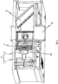
- FIG. 12 shows a perspective sectional view of an incident light attenuating device 100 according to the invention of a finite-widening beam according to one embodiment of the invention.
- FIG. The arrangement 100 is used here by way of example in a scattered-light smoke detector, which in its lower region a feed opening 60 for supplying ambient air into a (in Fig. 1 unspecified) useful light region 50 has.
- a light source which is generally designated 10.
- the light source has a light emitting diode 11 and a downstream of this LED 11 lens 12, which in turn are followed by a plurality of apertures 13, which bundle the light emitted from the light emitting diode 11 in total and introduce it into the Nutzlicht Schl.
- the Nutzlicht Scheme 50 is traversed by the unpolarized light, in the illustrated embodiment in Fig. 1 straight.
- Subordinate to the useful light region 50 in the direct beam direction of the light bundle is an absorption device 30, which serves to at least partially absorb the incident light.
- the absorber 30 has two sequentially arranged circular polarizers 31, 32 whose polarization rotation is equal to each other.
- a plurality of optical detectors 20a, 20b, 20c, 20d which serve to classify a scattered light signal possibly detected in the arrangement 100, are arranged around the useful light region 50 indicated by dashed lines.
- the optical detectors 20a, 20b, 20c, 20d have a photodiode 21a, 21b, 21c, 21d and one of these photodiode 21a, 21b, 21c, 21d downstream lens 22a, 22b, 22c, 22d, which in turn one or more apertures 23a, 23b, 23c, 23d are arranged downstream, each having a horizontally or vertically oriented linear polarization device 24a, 24b, 24c, 24d, for example, a linear polarization filter is assigned.
- Fig. 3 shows better, the exploding device 30 shown there for better illustration on a mounting device 35, which in the mounted state has a relation to the emitted light from the light source by about 45 ° in the direction of the bottom of the scattered light smoke detector inclined mounting surface.
- the circular polarization devices 31, 32 are arranged in a very small distance one behind the other, in the embodiment shown at a distance of 2 mm behind each other, which in a very effective manner, the directly incident monochromatic light of the light emitting diode 11, which bundles through the lens 12 and attenuated through the apertures 13 into the useful light region 50, so that its intensity is sufficiently small that it is not undesirably detected by the optical detectors 20a, 20b, 20c, 20d due to multiple reflection or the like.
Landscapes
- Chemical & Material Sciences (AREA)
- Analytical Chemistry (AREA)
- Physics & Mathematics (AREA)
- General Physics & Mathematics (AREA)
- Business, Economics & Management (AREA)
- Emergency Management (AREA)
- Health & Medical Sciences (AREA)
- Life Sciences & Earth Sciences (AREA)
- Biochemistry (AREA)
- General Health & Medical Sciences (AREA)
- Immunology (AREA)
- Pathology (AREA)
- Investigating Or Analysing Materials By Optical Means (AREA)
- Fire-Detection Mechanisms (AREA)
- Non-Portable Lighting Devices Or Systems Thereof (AREA)
Description
Die vorliegende Erfindung betrifft eine Anordnung zum Abschwächen auftreffenden Lichts eines Strahlenbündels.The present invention relates to an arrangement for attenuating incident light of a beam.
Die Druckschrift
Die Druckschrift
In bestimmten technischen Einrichtungen wie beispielsweise Streulicht-Rauchmeldeeinrichtungen wird gezielt Licht in einen Nutzlichtbereich, beispielsweise in einen Streulichtbereich eingeleitet und dort eventuell auftretende Reflexionen mittels eines oder mehrerer optischen Detektoren wie beispielsweise Fotodioden und dergleichen erfasst. In Streulicht-Rauchmeldern breitet sich in der Regel nahezu monochromatisches Licht oder Infrarotstrahlung einer Laser- oder Leuchtdiode geradlinig ausgehend von der Lichtquelle in den Nutzlichtbereich aus. Wird es dort von eventuell vorhandenen Rauchpartikeln oder dergleichen gestreut, so trifft eine geringe Lichtmenge dieses gestreuten (gegebenenfalls reflektierten) Lichts auf die um den Nutzlichtbereich herum angeordneten optischen Detektoren, wodurch in diesen ein Signal erzeugt wird. Je nach Anwendungsfall kommen hierbei unterschiedliche Signalauswertungsmethoden zum Einsatz; falls eine entsprechende Bedingungen erfüllt ist, kann ein derartiger Streulicht-Rauchmelder ein Alarmsignal oder dergleichen ausgeben.In certain technical devices, such as, for example, scattered-light smoke detection devices, light is deliberately introduced into a useful light region, for example into a scattered light region, and any reflections occurring there are detected by means of one or more optical detectors, such as, for example, photodiodes and the like. In scattered light smoke detectors, almost monochromatic light or infrared radiation from a laser or light-emitting diode generally propagates in a straight line from the light source to the useful light region. If it is scattered there by possibly existing smoke particles or the like, a small amount of light of this scattered (possibly reflected) light strikes the optical detectors arranged around the useful light region, whereby a signal is generated in these. Depending on the application, different signal evaluation methods are used here; if a corresponding condition is met, such a scattered light smoke detector can emit an alarm signal or the like.
Bei diesen Anwendungsfällen ist es von großer Wichtigkeit, dass durch konstruktive Maßnahmen sichergestellt ist, dass neben dem Streulicht, welches tatsächlich an zu erkennenden in dem Nutzlichtbereich befindlichen Partikeln gestreut bzw. reflektiert wurde, möglichst wenig vagabundierendes Licht auf die optischen Detektoren trifft. Vagabundierendes Licht ist Licht, welches beispielsweise von den Innenwänden oder dergleichen des Streulicht-Raumelders reflektiert wurde. Wenn zu viel vagabundierendes Licht auf die optischen Detektoren trifft, erzeugen die optischen Detektoren ein zu hohes Hintergrundsignal, so dass das Streulicht sich kaum von diesem Hintergrundsignal abhebt und daher schwer oder gar nicht gemessen werden kann. Insbesondere bei hochsensiblen Streulicht-Raumeldern ist eine hohe Verstärkung der Streulichtsignale nötig, die bei hohen Hintergrundsignalen zu einer Übersteuerung der Verstärker führen würde.In these applications, it is of great importance that it is ensured by constructive measures that in addition to the scattered light, which was actually scattered or reflected on to be recognized in the Nutzlichtbereich particles, as little stray light on the optical detectors meets. Vagabonding light is light that has been reflected, for example, by the inner walls or the like of the scattered light spaceter. If too much stray light strikes the optical detectors, the optical detectors will produce too much background signal so that the stray light will hardly stand out from this background signal and therefore can be difficult or impossible to measure. Particularly in the case of highly sensitive scattered light field fields, a high amplification of the scattered light signals is necessary, which would lead to overdriving of the amplifiers with high background signals.
Zur Abschwächung bzw. Absorption unerwünschten Lichts sind sogenannte Lichtfallen bekannt. Aus der Druckschrift
Die aus der
Ausgehend von dieser Problemstellung liegt der vorliegenden Erfindung die Aufgabe zugrunde, eine Anordnung zum Abschwächen auftreffenden Lichts eines Strahlenbündels mit endlicher Aufweitung anzugeben, welche einen vergleichsweisen einfachen Aufbau aufweist und zur Absorption (zum Abschwächen) direkt auftreffenden Lichts einer Lichtquelle wie beispielsweise einer Laser-Lichtquelle oder dergleichen geeignet ist.Based on this problem, the present invention seeks to provide an arrangement for attenuating incident light of a beam with finite expansion, which a comparatively has a simple structure and is suitable for absorbing (attenuating) directly incident light of a light source such as a laser light source or the like.
Erfindungsgemäß wird die Aufgabe gelöst durch eine Anordnung zum Abschwächen auftreffenden Lichts eines Strahlenbündels mit endlicher Aufweitung, welche die Merkmale des unabhängigen Patentanspruchs 1 aufweist.According to the invention the object is achieved by an arrangement for attenuating incident light of a beam with finite expansion, which has the features of independent claim 1.
Insbesondere wird die Aufgabe gelöst durch eine Anordnung zum Abschwächen auftreffenden Lichts eines Strahlenbündels mit endlicher Aufweitung, vorzugsweise direkt auftreffenden monochromatischen Lichts, wobei die Anordnung eine Lichtquelle zum Erzeugen eines Lichtbündels unpolarisierten Lichts, vorzugsweise unpolarisierten monochromatischen Lichts, einen Nutzlichtbereich, den das unpolarisierte Licht durchläuft und vorzugsweise ausgehend von der Lichtquelle geradlinig durchläuft, sowie eine dem Nutzlichtbereich nachgeordnete und vorzugsweise in direkter Strahlrichtung des Lichtbündels nachgeordnete Absorptionseinrichtung zum zumindest teilweisen Absorbieren auftreffenden Lichts aufweist, wobei die Absorptionseinrichtung mindestens eine in Richtung des Lichtbündels angeordnete Polarisationseinrichtung aufweist.In particular, the object is achieved by an arrangement for attenuating incident light of a beam with finite expansion, preferably directly incident monochromatic light, wherein the arrangement comprises a light source for generating a light beam unpolarized light, preferably unpolarisierten monochromatic light, a Nutzlichtbereich which passes through the unpolarized light and Preferably, starting from the light source passes straight through, and a downstream of the Nutzlichtbereich and preferably downstream in the direct beam direction of the light beam absorption device for at least partially absorbing incident light, wherein the absorption device has at least one arranged in the direction of the light beam polarization device.
Durch die Verwendung mindestens einer Polarisationseinrichtung ist auf überraschend einfache Weise eine zuverlässige Abschwächung des direkt auftreffenden Lichtbündels möglich, nachdem dieses den Nutzlichtbereich unpolarisiert durchlaufen hat. Dadurch, dass Polarisationseinrichtungen kostengünstig verfügbar sind, ist es somit auf ökonomisch vorteilhafte Weise einfach möglich, das durch vagabundierendes Licht erzeugte Hintergrundsignal bei Vorrichtungen wirksam zu minimieren, welche von einer derartigen Anordnung Gebrauch machen. Dies gilt ganz besonders für den Fall, dass die Absorptionseinrichtung dem Nutzlichtbereich in direkter Strahlrichtung des Lichtbündels nachgeordnet ist, mit anderen Worten also von dem gesamten relativ starken Strahlbündel beaufschlagt wird, welches beispielsweise aus einer monochromatischen Laserlichtquelle oder aus einer nahezu monochromatischen LED-Lichtquelle stammt.By using at least one polarization device, a reliable attenuation of the directly incident light beam is possible in a surprisingly simple manner, after it has passed through the unpolarized useful light region. Thus, by making polarization devices available at low cost, it is easily possible in an economically advantageous manner to effectively minimize the background signal generated by stray light in devices that make use of such an arrangement. This is particularly true in the event that the absorption device is arranged downstream of the useful light region in the direct beam direction of the light beam, in other words is acted upon by the entire relatively strong beam, which originates for example from a monochromatic laser light source or from an almost monochromatic LED light source.
Vorteilhafte Weiterbildungen der erfindungsgemäßen Lösung sind in den abhängigen Ansprüchen angegeben.Advantageous developments of the solution according to the invention are specified in the dependent claims.
So ist es beispielsweise vorgesehen, dass um den Nutzlichtbereich herum mindestens ein optischer Detektor zum Detektieren von Streulicht angeordnet ist. Wenn also nicht lediglich das Auftreten von Streulicht, welches negativ in den Nutzlichtbereich zurückwirkt, vermieden werden soll, sondern ganz gezielt um diesen Nutzlichtbereich herum eine optische Erkennung stattfindet, dann kann mit der erfindungsgemäßen Anordnung eine noch bessere Genauigkeit der optischen Detektion erreicht werden, was das Hintergrundsignal aufgrund von ungewollt in den Nutzlichtbereich zurückgestreuten Streulicht weiter verringert.For example, it is provided that at least one optical detector for detecting scattered light is arranged around the useful light region. Thus, if not only the occurrence of stray light, which negatively reverts back into the useful light range, but rather an optical recognition takes place in a targeted manner around this useful light range, an even better accuracy of the optical detection can be achieved with the arrangement according to the invention Background signal due to unwanted backscattered scattered in the Nutzlichtbereich scattered light further reduced.
Gemäß einem weiteren Aspekt der Erfindung ist es vorgesehen, dass die Absorptionseinrichtung mindestens zwei in Richtung des Lichtbündels aufeinanderfolgend angeordnete Polarisationseinrichtungen aufweist. Es hat sich überraschend herausgestellt, dass durch die aufeinanderfolgende Anordnung mindestens zweier Polarisationseinrichtungen zum Absorbieren des auftreffenden Lichtbündels die Absorptionseigenschaften nochmals signifikant verbessert werden können.According to another aspect of the invention, it is provided that the absorption device has at least two polarization devices arranged successively in the direction of the light bundle. It has surprisingly been found that the absorption properties can be significantly improved again by the successive arrangement of at least two polarization devices for absorbing the incident light beam.
In Anknüpfung an diese Weiterbildung ist es beispielsweise vorgesehen, dass die mindestens zwei Polarisationseinrichtungen einen ersten linearen Polarisationsfilter und einen zweiten linearen Polarisationsfilter aufweisen. Hierbei sind die Polarisationsrichtungen des ersten und des zweiten linearen Polarisationsfilters um 90° zueinander versetzt. Durch eine derartige Verdrehung der Polarisationsebenen der beiden linearen Polarisationsfilter, welche in Richtung des Lichtbündels aufeinanderfolgend angeordnet sind, kann die Absorptionswirkung nochmals verbessert werden.In connection with this development, it is provided, for example, that the at least two polarization devices have a first linear polarization filter and a second linear polarization filter. Here, the polarization directions of the first and the second linear polarization filter are offset by 90 ° to each other. By such a rotation of the polarization planes of the two linear polarizing filters, which are arranged successively in the direction of the light bundle, the absorption effect can be further improved.
Alternativ ist es in Anknüpfung an die vorgenannte Weiterbildung möglich, dass die mindestens zwei Polarisationseinrichtungen einen ersten zirkularen Polarisationsfilter und einen zweiten zirkularen Polarisationsfilter aufweisen. Der Polarisations-Drehsinn des ersten Polarisationsfilters in Richtung des einfallenden Lichtbündels ist hierbei gleich dem Polarisations-Drehsinn des zweiten Polarisationsfilters in Richtung des einfallenden Lichtbündels. Mit anderen Worten: Die beiden in Richtung des Lichtbündels aufeinanderfolgend angeordneten zirkularen Polarisationsfilter sind nicht gegensinnig zueinander verdreht. Im Vergleich zu den aufeinander folgend angeordneten linearen Polarisationsfiltern kann bei dieser Weiterbildung der Erfindung eine nochmals verbesserte, ausgezeichnete Absorptionswirkung erzielt werden.Alternatively, it is possible in connection with the aforementioned development that the at least two polarization devices have a first circular polarization filter and a second circular polarization filter. The polarization rotation direction of the first polarization filter in the direction of the incident light bundle is in this case equal to the polarization rotation direction of the second polarization filter in the direction of the incident light bundle. In other words, the two circular polarization filters arranged successively in the direction of the light beam are not rotated in opposite directions to one another. In comparison with the successively arranged linear polarization filters, a further improved, excellent absorption effect can be achieved in this development of the invention.
Es ist jedoch ebenfalls möglich, dass auch die Polarisationsrichtung des ersten zirkularen Polarisationsfilters zu derjenigen des zweiten zirkularen Polarisationsfilters um 90° versetzt ist.However, it is also possible that the polarization direction of the first circular polarizing filter is also offset by 90 ° from that of the second circular polarizing filter.
Bei den Weiterbildungen mit den zirkularen Polarisationsfiltern kann zusätzlich ein linearer Polarisationsfilter vorgesehen sein, welcher dem mindestens einen optischen Detektor zugeordnet ist. Mit anderen Worten: Direkt vor dem mindestens einen optischen Detektor ist ein linearer Polarisationsfilter angeordnet, während die zwei zirkularen Polarisationsfilter gleichen Drehsinns direkt in Richtung des Lichtbündels aufeinanderfolgend angeordnet sind und dieses Lichtbündel abschwächen, nachdem es den Nutzlichtbereich durchquert hat. Hierdurch kann das durch vagabundierendes Licht erzeugte Hintergrundsignal an dem mindestens einen optischen Detektor noch weiter reduziert werden.In the developments with the circular polarization filters, a linear polarization filter can additionally be provided, which is assigned to the at least one optical detector. In other words, a linear polarization filter is arranged directly in front of the at least one optical detector, while the two circular polarization filters of the same direction of rotation are arranged directly successively in the direction of the light bundle and weaken this light bundle after it has traversed the useful light region. As a result, the background signal generated by stray light can be further reduced at the at least one optical detector.
Gemäß einem weiteren Aspekt der erfindungsgemäßen Lösung ist es vorgesehen, dass die mindestens eine Polarisationseinrichtung wechselbar in einer dem Nutzlichtbereich in Richtung des Lichtbündels nachgeordneten Halterungseinrichtung aufgenommen ist. Hierdurch wird die Handhabung der Absorptionseinrichtung erleichtert und vereinfacht, beispielsweise dann, wenn die Polarisationseinrichtung bzw. die Polarisationseinrichtungen ausgetauscht werden sollen. Durch eine derartige Halterung ist zudem eine einfache Nachrüstbarkeit vorhandener Vorrichtungen möglich, welche sich der erfindungsgemäßen Anordnung bedienen sollen.In accordance with a further aspect of the solution according to the invention, it is provided that the at least one polarization device is exchangeably received in a mounting device downstream of the useful light region in the direction of the light bundle. This facilitates and simplifies the handling of the absorption device, for example when the polarization device or the polarization devices are to be exchanged. By such a holder a simple retrofitting of existing devices is also possible, which should use the inventive arrangement.
Gemäß einem weiteren Aspekt der erfindungsgemäßen Lösung ist es vorgesehen, dass die Lichtquelle eine Leuchtdiode und vorzugsweise mindestens eine Linse sowie vorzugsweise mindestens eine Blende aufweist. Ein derartiges optisches System ist verhältnismäßig einfach und damit kostengünstig herzustellen und erlaubt gleichzeitig eine gezielte Beaufschlagung des Nutzlichtbereichs mit dem zu nutzenden Licht oder Infrarot- oder Ultraviolettstrahlung.According to a further aspect of the solution according to the invention, it is provided that the light source has a light-emitting diode and preferably at least one lens and preferably at least one diaphragm. Such an optical system is relatively simple and therefore inexpensive to manufacture and at the same time allows a targeted exposure of the Nutzlichtbereich with the light to be used or infrared or ultraviolet radiation.
Gemäß einem weiteren Aspekt der erfindungsgemäßen Lösung ist es vorgesehen, dass der mindestens eine optische Detektor eine Fotodiode und vorzugsweise mindestens eine Linse sowie vorzugsweise mindestens eine Blende aufweist. Ebenso gilt auch bei diesem optischen System, dass es relativ kostengünstig bereitgestellt werden kann und gleichzeitig eine hohe Erkennungsgenauigkeit bietet.According to a further aspect of the solution according to the invention, it is provided that the at least one optical detector has a photodiode and preferably at least one lens and preferably at least one diaphragm. Likewise with this optical system as well, it can be provided relatively inexpensively and at the same time offers high recognition accuracy.
Gemäß einem weiteren Aspekt der Erfindung ist es vorgesehen, dass die mindestens zwei Polarisationseinrichtungen in Richtung des Lichtbündels in einem Abstand von weniger als 5 mm und vorzugsweise von weniger als 2 mm voneinander beabstandet sind. Durch eine verhältnismäßig geringe Beabstandung der beiden Polarisationseinrichtungen voneinander in Richtung des Lichtbündels kann die Absorptionsleistung nochmals verbessert werden.According to a further aspect of the invention, it is provided that the at least two polarization devices are spaced apart in the direction of the light beam by a distance of less than 5 mm, and preferably of less than 2 mm. By a relatively small spacing of the two polarizing devices from each other in the direction of the light beam, the absorption performance can be further improved.
Gemäß einem weiteren Aspekt der Erfindung ist es vorgesehen, dass die mindestens eine Polarisationseinrichtung in Bezug auf die Richtung des einfallenden Lichtbündels in einem Winkel geneigt ist, wobei der Winkel zwischen dem einfallenden Lichtbündel und einer Detektorebene gebildet wird, innerhalb welcher die optische Mittelachse des mindestens einen Detektors angeordnet ist, und wobei der Winkel vorzugsweise etwa 45° beträgt. Mit anderen Worten: Die mindestens eine Polarisationseinrichtung und in bevorzugter Weise die mindestens zwei Polarisationseinrichtungen ist bzw. sind gemeinsam relativ zum einfallenden Lichtbündel verkippt, sodass gegebenenfalls nicht von der Absorptionseinrichtung absorbiertes bzw. nicht ausreichend abgeschwächtes einfallendes Licht nicht auf dem gleichen Weg zurück reflektiert wird, auf welchem es eingefallen ist. Es kann dann, wenn die Anordnung in einem Streulichtrauchmelder zum Einsatz kommt, durch die Verkippung vielmehr auf den Boden des Streulichtrauchmelders reflektiert werden. Hierdurch wird die Leistungsfähigkeit der Anordnung dahingehend gesteigert, dass unerwünschtes Streulicht in dem Nutzlichtbereich noch besser vermieden werden kann.According to a further aspect of the invention, it is provided that the at least one polarization device is inclined at an angle with respect to the direction of the incident light beam, wherein the angle between the incident light beam and a detector plane is formed, within which the optical center axis of the at least one Detector is arranged, and wherein the angle is preferably about 45 °. In other words, the at least one polarization device and preferably the at least two polarization devices are or are tilted together relative to the incident light bundle so that incident light not absorbed by the absorption device or not sufficiently attenuated is not reflected back in the same way, on which it has fallen. When the arrangement is used in a scattered light smoke detector, it can be reflected by the tilt rather on the bottom of the scattered light smoke detector. As a result, the performance of the arrangement is increased so that unwanted scattered light in the Nutzlichtbereich can be even better avoided.
Die Erfindung ist auch gerichtet auf einen Streulicht-Rauchmelder mit mindestens einer Zufuhröffnung zum Zuführen von Umgebungsluft und mit einer oben beschriebenen erfindungsgemäßen Anordnung, wobei die Zufuhröffnung in einen Streulichtbereich mündet, und wobei der Streulichtbereich zumindest bereichsweise dem Nutzlichtbereich entspricht.The invention is also directed to a scattered light smoke detector with at least one supply opening for supplying ambient air and with an inventive arrangement described above, wherein the supply opening opens into a scattered light area, and wherein the scattered light area at least partially corresponds to the Nutzlichtbereich.
Nachfolgend wird eine Ausführungsform der erfindungsgemäßen Anordnung zum Abschwächen auftreffenden Lichts eines Strahlenbündels mit endlicher Aufweitung anhand einer Zeichnung näher erläutert. In den Zeichnungen zeigen:
- Fig. 1:
- eine perspektivische Schnittansicht einer erfindungsgemäßen Anordnung zum Abschwächen auftreffenden Lichts gemäß einer Ausführungsform der Erfindung;
- Fig. 2:
- eine schematische Draufsicht auf die Anordnung aus
Fig. 1 ; und - Fig. 3:
- eine perspektivische Draufsicht auf die Anordnung aus den
Figuren 1 und2 , wobei deren Absorptionseinrichtung zur besseren Veranschaulichung in Explosionsdarstellung dargestellt ist.
- Fig. 1:
- a sectional perspective view of an inventive arrangement for attenuating incident light according to an embodiment of the invention;
- Fig. 2:
- a schematic plan view of the arrangement
Fig. 1 ; and - 3:
- a top perspective view of the arrangement of the
FIGS. 1 and2 , Whose absorption device is shown for better illustration in an exploded view.
Wie aus der schematischen Draufsicht aus
Wie aus der perspektivischen Draufsicht aus
Es versteht sich, dass das dargestellte Ausführungsbeispiel lediglich der besseren Erläuterung dient und nicht einschränkend aufzufassen ist. Ergänzungen und Abwandlungen der erfinderischen Idee sind dem Fachmann geläufig.It is understood that the illustrated embodiment is only for better illustration and is not to be construed restrictive. Additions and modifications of the inventive idea are familiar to the person skilled in the art.
- 1010
- Lichtquellelight source
- 1111
- Leuchtdiodeled
- 1212
- Linselens
- 1313
- Blendendazzle
- 20a, 20b, 20c, 20d20a, 20b, 20c, 20d
- optischer Detektoroptical detector
- 21a, 21b, 21c, 21d21a, 21b, 21c, 21d
- Fotodiodenphotodiodes
- 22a, 22b, 22c, 22d22a, 22b, 22c, 22d
- Linsenlenses
- 23a, 23b, 23c, 23d23a, 23b, 23c, 23d
- Blendendazzle
- 24a, 24b, 24c, 24d24a, 24b, 24c, 24d
- lineare Polarisationsfilterlinear polarization filter
- 3030
- Absorptionseinrichtungabsorber
- 3131
- erste Polarisationseinrichtungfirst polarization device
- 3232
- zweite Polarisationseinrichtungsecond polarization device
- 3535
- Halterungseinrichtungsupport means
- 5050
- NutzlichtbereichNutzlichtbereich
- 6060
- Zuführöffnungfeed
- 100100
- Anordnung zum Abschwächen auftreffenden LichtsArrangement for attenuating incident light
Claims (13)
- An assembly for attenuating impinging light of a beam of finite expansion, preferably directly impinging monochromatic light, wherein the assembly comprises the following:- a light source (10) for producing a beam of unpolarized light, preferably unpolarized monochromatic light;- a useful light region (50) through which the unpolarized light passes, and preferably passes through in a straight line from the light source (10);- an absorption device (30) arranged downstream of the useful light region (50), and preferably downstream in the direction of the direct beam radiation, for at least partly absorbing impinging light,wherein the absorption device (30) comprises at least one polarization device (31, 32) arranged in the direction of the light beam.
- The assembly (100) according to claim 1,
wherein at least one optical detector (20a, 20b, 20c, 20d) is arranged around the useful light region (50) for detecting scattered light. - The assembly (100) according to claim 1 or 2,
wherein the absorption device (30) comprises at least two polarization devices (31, 32) arranged successively in the direction of the beam of light. - The assembly (100) according to claim 3,
wherein the at least two polarization devices (31, 32) comprise a first linear polarizing filter and a second linear polarizing filter, wherein the polarizing directions of the first and second linear polarizing filter are offset 90° from one another. - The assembly (100) according to claim 3,
wherein the at least two polarization devices (31, 32) comprise a first circular polarizing filter and a second circular polarizing filter, wherein the polarizing directions of the first and second circular polarizing filter are offset 90° from one another. - The assembly (100) according to claim 3,
wherein the at least two polarization devices (31, 32) comprise a first circular polarizing filter and a second circular polarizing filter, wherein the rotational direction of polarization of the first polarizing filter in the direction of the impinging beam of light and the rotational direction of polarization of the second polarizing filter in the direction of the impinging beam of light is equal. - The assembly (100) according to claim 5 or 6,
wherein the at least one optical detector (20a, 20b, 20c, 20d) is assigned to a linear polarizing filter (21a, 21b, 21c, 21d). - The assembly (100) according to any one of the preceding claims,
wherein the at least one polarization device (31, 32) is exchangeably accommodated in a retaining device (35) arranged downstream the useful light region in the direction of the light beam. - The assembly (100) according to any one of the preceding claims,
wherein the light source comprises a light-emitting diode (11) and preferably at least one lens (12) and preferably at least one aperture (13). - The assembly (100) according to any one of claims 2 to 9,
wherein the at least one optical detector comprises a photodiode and preferably at least one lens and preferably at least one aperture. - The assembly (100) according to any one of claims 3 to 10,
wherein the at least two polarization devices are spaced apart from one another in the direction of the beam of light at a distance of less than 5 mm, preferably less than 2 mm. - The assembly (100) according to any one of the preceding claims,
wherein the at least one polarization device is slanted at an angle relative to the direction of the impinging beam of light, wherein the angle is formed between the impinging beam of light and a detection plane within which the central optical axis of the least one detector is arranged, and wherein the angle preferably amounts to approximately 45°. - A scattered light smoke detector having at least one supply opening for supplying ambient air and an assembly in accordance with any one of claims 1 to 12, wherein the feed opening empties into a scattered light region, and wherein at least part of the scattered light region corresponds to the useful light region.
Priority Applications (10)
| Application Number | Priority Date | Filing Date | Title |
|---|---|---|---|
| PL14175734.4T PL2963627T3 (en) | 2014-07-04 | 2014-07-04 | Assembly for damping the impinging light of a beam of radiation |
| ES14175734.4T ES2587128T3 (en) | 2014-07-04 | 2014-07-04 | Willingness to dim incident light from a beam of rays |
| EP14175734.4A EP2963627B1 (en) | 2014-07-04 | 2014-07-04 | Assembly for damping the impinging light of a beam of radiation |
| CA2946921A CA2946921C (en) | 2014-07-04 | 2015-03-25 | Assembly for attenuating impinging light of a beam of radiation |
| CN201580025948.5A CN106463037A (en) | 2014-07-04 | 2015-03-25 | Arrangement for attenuating impinging light of a beam |
| RU2017102957A RU2651644C1 (en) | 2014-07-04 | 2015-03-25 | Device for attenuation of the radiation beam incident light |
| AU2015283230A AU2015283230B2 (en) | 2014-07-04 | 2015-03-25 | Arrangement for attenuating impinging light of a beam |
| US15/317,194 US9964486B2 (en) | 2014-07-04 | 2015-03-25 | Assembly for attenuating impinging light of a beam of radiation |
| MX2016014374A MX357728B (en) | 2014-07-04 | 2015-03-25 | Arrangement for attenuating impinging light of a beam. |
| PCT/EP2015/056361 WO2016000837A1 (en) | 2014-07-04 | 2015-03-25 | Arrangement for attenuating impinging light of a beam |
Applications Claiming Priority (1)
| Application Number | Priority Date | Filing Date | Title |
|---|---|---|---|
| EP14175734.4A EP2963627B1 (en) | 2014-07-04 | 2014-07-04 | Assembly for damping the impinging light of a beam of radiation |
Publications (2)
| Publication Number | Publication Date |
|---|---|
| EP2963627A1 EP2963627A1 (en) | 2016-01-06 |
| EP2963627B1 true EP2963627B1 (en) | 2016-05-18 |
Family
ID=51133908
Family Applications (1)
| Application Number | Title | Priority Date | Filing Date |
|---|---|---|---|
| EP14175734.4A Active EP2963627B1 (en) | 2014-07-04 | 2014-07-04 | Assembly for damping the impinging light of a beam of radiation |
Country Status (10)
| Country | Link |
|---|---|
| US (1) | US9964486B2 (en) |
| EP (1) | EP2963627B1 (en) |
| CN (1) | CN106463037A (en) |
| AU (1) | AU2015283230B2 (en) |
| CA (1) | CA2946921C (en) |
| ES (1) | ES2587128T3 (en) |
| MX (1) | MX357728B (en) |
| PL (1) | PL2963627T3 (en) |
| RU (1) | RU2651644C1 (en) |
| WO (1) | WO2016000837A1 (en) |
Families Citing this family (4)
| Publication number | Priority date | Publication date | Assignee | Title |
|---|---|---|---|---|
| PL2963627T3 (en) * | 2014-07-04 | 2016-11-30 | Assembly for damping the impinging light of a beam of radiation | |
| US10852233B2 (en) * | 2016-06-15 | 2020-12-01 | Kidde Technologies, Inc. | Systems and methods for chamberless smoke detection and indoor air quality monitoring |
| US10871452B2 (en) * | 2016-06-15 | 2020-12-22 | Kidde Technologies, Inc. | Systems and methods for chamberless smoke detection and indoor air quality monitoring |
| CN111610206B (en) * | 2020-06-23 | 2021-03-30 | 中国科学院高能物理研究所 | Coherent X-ray protection, monitoring and intelligent attenuation integrated device |
Family Cites Families (21)
| Publication number | Priority date | Publication date | Assignee | Title |
|---|---|---|---|---|
| US5502434A (en) * | 1992-05-29 | 1996-03-26 | Hockiki Kabushiki Kaisha | Smoke sensor |
| CH684556A5 (en) * | 1992-09-14 | 1994-10-14 | Cerberus Ag | Optical Smoke Detector. |
| US5576697A (en) * | 1993-04-30 | 1996-11-19 | Hochiki Kabushiki Kaisha | Fire alarm system |
| AUPQ553800A0 (en) * | 2000-02-10 | 2000-03-02 | Cole, Martin Terence | Improvements relating to smoke detectors particularily duct monitored smoke detectors |
| US6909459B2 (en) * | 2002-08-21 | 2005-06-21 | Alpha Innotech Corporation | Method of and apparatus for extending signal ranges of digital images |
| KR20060040582A (en) * | 2003-06-09 | 2006-05-10 | 웨이비엔, 인코포레이티드 | A light pipe based projection engine |
| US7268881B2 (en) * | 2004-02-17 | 2007-09-11 | The Curators Of The University Of Missouri | Light scattering detector |
| US7253902B2 (en) * | 2004-03-31 | 2007-08-07 | Mitutoyo Corporation | Wavelength detector |
| US20070021807A1 (en) * | 2005-07-20 | 2007-01-25 | Eastman Kodak Company | Device for optically stimulating collagen formation in tissue |
| DE102005045280B3 (en) | 2005-09-22 | 2006-12-28 | Leuze Electronic Gmbh & Co Kg | Distance sensor has receiver with light sensitive surface enclosed by frame with normal vector inclined to optical axis by defined angle so received light beams incident on frame are deflected to side, no longer pass into monitored region |
| US20070153122A1 (en) * | 2005-12-30 | 2007-07-05 | Ayite Nii A | Apparatus and method for simultaneous multiple video channel viewing |
| KR100802199B1 (en) * | 2006-05-25 | 2008-03-17 | 정경희 | Optical module and fabrication method of the same |
| US7669457B2 (en) * | 2007-07-24 | 2010-03-02 | Honeywell International Inc. | Apparatus and method of smoke detection |
| US7852475B2 (en) * | 2007-08-13 | 2010-12-14 | Jds Uniphase Corporation | Scanning spectrometer with multiple photodetectors |
| DE102007055771A1 (en) * | 2007-12-12 | 2009-06-18 | Hilti Aktiengesellschaft | Laser Distance Meter |
| US8390806B1 (en) * | 2009-05-21 | 2013-03-05 | Lockheed Martin Corporation | MEMS spectrometer and sensing systems therefrom |
| JPWO2011115293A1 (en) * | 2010-03-19 | 2013-07-04 | 古河電気工業株式会社 | Polarization-independent wavelength converter and polarization-independent wavelength conversion method |
| KR20120074558A (en) * | 2010-12-28 | 2012-07-06 | 삼성전자주식회사 | Apparatus for detection of microparticle |
| US9995623B2 (en) * | 2013-03-14 | 2018-06-12 | Integrated Plasmonics Corporation | Ambient light assisted spectroscopy |
| TWI507742B (en) * | 2013-11-26 | 2015-11-11 | E Ink Holdings Inc | Color filter substrate and display device |
| PL2963627T3 (en) * | 2014-07-04 | 2016-11-30 | Assembly for damping the impinging light of a beam of radiation |
-
2014
- 2014-07-04 PL PL14175734.4T patent/PL2963627T3/en unknown
- 2014-07-04 ES ES14175734.4T patent/ES2587128T3/en active Active
- 2014-07-04 EP EP14175734.4A patent/EP2963627B1/en active Active
-
2015
- 2015-03-25 RU RU2017102957A patent/RU2651644C1/en active
- 2015-03-25 US US15/317,194 patent/US9964486B2/en active Active
- 2015-03-25 MX MX2016014374A patent/MX357728B/en active IP Right Grant
- 2015-03-25 WO PCT/EP2015/056361 patent/WO2016000837A1/en active Application Filing
- 2015-03-25 CN CN201580025948.5A patent/CN106463037A/en active Pending
- 2015-03-25 AU AU2015283230A patent/AU2015283230B2/en active Active
- 2015-03-25 CA CA2946921A patent/CA2946921C/en active Active
Also Published As
| Publication number | Publication date |
|---|---|
| EP2963627A1 (en) | 2016-01-06 |
| WO2016000837A1 (en) | 2016-01-07 |
| CA2946921A1 (en) | 2016-01-07 |
| RU2651644C1 (en) | 2018-04-23 |
| PL2963627T3 (en) | 2016-11-30 |
| US9964486B2 (en) | 2018-05-08 |
| AU2015283230A1 (en) | 2016-11-10 |
| MX357728B (en) | 2018-07-20 |
| US20170153177A1 (en) | 2017-06-01 |
| CA2946921C (en) | 2019-01-15 |
| MX2016014374A (en) | 2017-01-20 |
| AU2015283230B2 (en) | 2018-06-14 |
| ES2587128T3 (en) | 2016-10-20 |
| CN106463037A (en) | 2017-02-22 |
Similar Documents
| Publication | Publication Date | Title |
|---|---|---|
| DE102015207289A1 (en) | Particle sensor device | |
| EP3521810A1 (en) | Analyser for the determination of fine dust | |
| EP2836818B1 (en) | Gas detector system | |
| DE102011113147B3 (en) | Optical distance measuring device for high-pressure discharge lamp, has object beam moved in direction of optical axis of receiving optical unit and emitted from mirror element, where mirror element lies on outer side of optical unit | |
| EP2963627B1 (en) | Assembly for damping the impinging light of a beam of radiation | |
| EP3990887B1 (en) | Sensor assembly for characterising particles | |
| WO2018149708A1 (en) | Lidar sensor for detecting an object | |
| EP2157449B1 (en) | Light grid | |
| DE10247136A1 (en) | Protection device for monitoring a protected area to be moved with a component | |
| EP2093731A1 (en) | Linear optical smoke alarm with multiple part-beams | |
| DE202009007612U1 (en) | Reflection light barrier sensor | |
| EP1780559B1 (en) | Optical sensor | |
| WO2019086552A1 (en) | Novel sensor for raman spectroscopy | |
| DE102018212823A1 (en) | LIDAR device for detecting an object | |
| EP1574880B2 (en) | Emitter for light barrier, light curtain or similar | |
| EP3096130A2 (en) | Device for identification of aerosols | |
| DE4122305B4 (en) | Device for optoelectronic scanning of a thread | |
| EP3743710B1 (en) | Optical detection system for detecting a subtance in a measurement region | |
| DE102021112212A1 (en) | Optical sensor and method of operating an optical sensor | |
| EP3353592B1 (en) | Distance measuring device | |
| DE102012100746B4 (en) | Transmission unit for an optical sensor | |
| DD294794A5 (en) | DEVICE FOR MEASURING AEROSOLS AND AIR-DISTRIBUTED DUST | |
| EP2634598B1 (en) | Optical sensor | |
| EP3187906B1 (en) | Light barrier | |
| DE19639403A1 (en) | Opto-electronic sensor for identification of objects during monitoring |
Legal Events
| Date | Code | Title | Description |
|---|---|---|---|
| PUAI | Public reference made under article 153(3) epc to a published international application that has entered the european phase |
Free format text: ORIGINAL CODE: 0009012 |
|
| 17P | Request for examination filed |
Effective date: 20150303 |
|
| AK | Designated contracting states |
Kind code of ref document: A1 Designated state(s): AL AT BE BG CH CY CZ DE DK EE ES FI FR GB GR HR HU IE IS IT LI LT LU LV MC MK MT NL NO PL PT RO RS SE SI SK SM TR |
|
| AX | Request for extension of the european patent |
Extension state: BA ME |
|
| GRAP | Despatch of communication of intention to grant a patent |
Free format text: ORIGINAL CODE: EPIDOSNIGR1 |
|
| INTG | Intention to grant announced |
Effective date: 20160120 |
|
| GRAS | Grant fee paid |
Free format text: ORIGINAL CODE: EPIDOSNIGR3 |
|
| GRAA | (expected) grant |
Free format text: ORIGINAL CODE: 0009210 |
|
| AK | Designated contracting states |
Kind code of ref document: B1 Designated state(s): AL AT BE BG CH CY CZ DE DK EE ES FI FR GB GR HR HU IE IS IT LI LT LU LV MC MK MT NL NO PL PT RO RS SE SI SK SM TR |
|
| REG | Reference to a national code |
Ref country code: GB Ref legal event code: FG4D Free format text: NOT ENGLISH |
|
| REG | Reference to a national code |
Ref country code: CH Ref legal event code: EP |
|
| REG | Reference to a national code |
Ref country code: AT Ref legal event code: REF Ref document number: 801072 Country of ref document: AT Kind code of ref document: T Effective date: 20160615 Ref country code: IE Ref legal event code: FG4D Free format text: LANGUAGE OF EP DOCUMENT: GERMAN |
|
| REG | Reference to a national code |
Ref country code: DE Ref legal event code: R096 Ref document number: 502014000790 Country of ref document: DE |
|
| REG | Reference to a national code |
Ref country code: CH Ref legal event code: NV Representative=s name: FIAMMENGHI-FIAMMENGHI, CH |
|
| REG | Reference to a national code |
Ref country code: FR Ref legal event code: PLFP Year of fee payment: 3 |
|
| REG | Reference to a national code |
Ref country code: NL Ref legal event code: FP |
|
| REG | Reference to a national code |
Ref country code: LT Ref legal event code: MG4D |
|
| REG | Reference to a national code |
Ref country code: ES Ref legal event code: FG2A Ref document number: 2587128 Country of ref document: ES Kind code of ref document: T3 Effective date: 20161020 |
|
| PG25 | Lapsed in a contracting state [announced via postgrant information from national office to epo] |
Ref country code: NO Free format text: LAPSE BECAUSE OF FAILURE TO SUBMIT A TRANSLATION OF THE DESCRIPTION OR TO PAY THE FEE WITHIN THE PRESCRIBED TIME-LIMIT Effective date: 20160818 Ref country code: FI Free format text: LAPSE BECAUSE OF FAILURE TO SUBMIT A TRANSLATION OF THE DESCRIPTION OR TO PAY THE FEE WITHIN THE PRESCRIBED TIME-LIMIT Effective date: 20160518 Ref country code: LT Free format text: LAPSE BECAUSE OF FAILURE TO SUBMIT A TRANSLATION OF THE DESCRIPTION OR TO PAY THE FEE WITHIN THE PRESCRIBED TIME-LIMIT Effective date: 20160518 |
|
| PG25 | Lapsed in a contracting state [announced via postgrant information from national office to epo] |
Ref country code: SE Free format text: LAPSE BECAUSE OF FAILURE TO SUBMIT A TRANSLATION OF THE DESCRIPTION OR TO PAY THE FEE WITHIN THE PRESCRIBED TIME-LIMIT Effective date: 20160518 Ref country code: LV Free format text: LAPSE BECAUSE OF FAILURE TO SUBMIT A TRANSLATION OF THE DESCRIPTION OR TO PAY THE FEE WITHIN THE PRESCRIBED TIME-LIMIT Effective date: 20160518 Ref country code: HR Free format text: LAPSE BECAUSE OF FAILURE TO SUBMIT A TRANSLATION OF THE DESCRIPTION OR TO PAY THE FEE WITHIN THE PRESCRIBED TIME-LIMIT Effective date: 20160518 Ref country code: PT Free format text: LAPSE BECAUSE OF FAILURE TO SUBMIT A TRANSLATION OF THE DESCRIPTION OR TO PAY THE FEE WITHIN THE PRESCRIBED TIME-LIMIT Effective date: 20160919 Ref country code: RS Free format text: LAPSE BECAUSE OF FAILURE TO SUBMIT A TRANSLATION OF THE DESCRIPTION OR TO PAY THE FEE WITHIN THE PRESCRIBED TIME-LIMIT Effective date: 20160518 Ref country code: GR Free format text: LAPSE BECAUSE OF FAILURE TO SUBMIT A TRANSLATION OF THE DESCRIPTION OR TO PAY THE FEE WITHIN THE PRESCRIBED TIME-LIMIT Effective date: 20160819 |
|
| PG25 | Lapsed in a contracting state [announced via postgrant information from national office to epo] |
Ref country code: RO Free format text: LAPSE BECAUSE OF FAILURE TO SUBMIT A TRANSLATION OF THE DESCRIPTION OR TO PAY THE FEE WITHIN THE PRESCRIBED TIME-LIMIT Effective date: 20160518 Ref country code: SK Free format text: LAPSE BECAUSE OF FAILURE TO SUBMIT A TRANSLATION OF THE DESCRIPTION OR TO PAY THE FEE WITHIN THE PRESCRIBED TIME-LIMIT Effective date: 20160518 Ref country code: CZ Free format text: LAPSE BECAUSE OF FAILURE TO SUBMIT A TRANSLATION OF THE DESCRIPTION OR TO PAY THE FEE WITHIN THE PRESCRIBED TIME-LIMIT Effective date: 20160518 Ref country code: DK Free format text: LAPSE BECAUSE OF FAILURE TO SUBMIT A TRANSLATION OF THE DESCRIPTION OR TO PAY THE FEE WITHIN THE PRESCRIBED TIME-LIMIT Effective date: 20160518 Ref country code: EE Free format text: LAPSE BECAUSE OF FAILURE TO SUBMIT A TRANSLATION OF THE DESCRIPTION OR TO PAY THE FEE WITHIN THE PRESCRIBED TIME-LIMIT Effective date: 20160518 |
|
| REG | Reference to a national code |
Ref country code: DE Ref legal event code: R097 Ref document number: 502014000790 Country of ref document: DE |
|
| PG25 | Lapsed in a contracting state [announced via postgrant information from national office to epo] |
Ref country code: SM Free format text: LAPSE BECAUSE OF FAILURE TO SUBMIT A TRANSLATION OF THE DESCRIPTION OR TO PAY THE FEE WITHIN THE PRESCRIBED TIME-LIMIT Effective date: 20160518 |
|
| PLBE | No opposition filed within time limit |
Free format text: ORIGINAL CODE: 0009261 |
|
| STAA | Information on the status of an ep patent application or granted ep patent |
Free format text: STATUS: NO OPPOSITION FILED WITHIN TIME LIMIT |
|
| PG25 | Lapsed in a contracting state [announced via postgrant information from national office to epo] |
Ref country code: MC Free format text: LAPSE BECAUSE OF FAILURE TO SUBMIT A TRANSLATION OF THE DESCRIPTION OR TO PAY THE FEE WITHIN THE PRESCRIBED TIME-LIMIT Effective date: 20160518 |
|
| 26N | No opposition filed |
Effective date: 20170221 |
|
| REG | Reference to a national code |
Ref country code: IE Ref legal event code: MM4A |
|
| PG25 | Lapsed in a contracting state [announced via postgrant information from national office to epo] |
Ref country code: SI Free format text: LAPSE BECAUSE OF FAILURE TO SUBMIT A TRANSLATION OF THE DESCRIPTION OR TO PAY THE FEE WITHIN THE PRESCRIBED TIME-LIMIT Effective date: 20160518 |
|
| REG | Reference to a national code |
Ref country code: FR Ref legal event code: PLFP Year of fee payment: 4 |
|
| PG25 | Lapsed in a contracting state [announced via postgrant information from national office to epo] |
Ref country code: IE Free format text: LAPSE BECAUSE OF NON-PAYMENT OF DUE FEES Effective date: 20160704 |
|
| PG25 | Lapsed in a contracting state [announced via postgrant information from national office to epo] |
Ref country code: LU Free format text: LAPSE BECAUSE OF NON-PAYMENT OF DUE FEES Effective date: 20160704 |
|
| PG25 | Lapsed in a contracting state [announced via postgrant information from national office to epo] |
Ref country code: HU Free format text: LAPSE BECAUSE OF FAILURE TO SUBMIT A TRANSLATION OF THE DESCRIPTION OR TO PAY THE FEE WITHIN THE PRESCRIBED TIME-LIMIT; INVALID AB INITIO Effective date: 20140704 |
|
| PG25 | Lapsed in a contracting state [announced via postgrant information from national office to epo] |
Ref country code: MT Free format text: LAPSE BECAUSE OF FAILURE TO SUBMIT A TRANSLATION OF THE DESCRIPTION OR TO PAY THE FEE WITHIN THE PRESCRIBED TIME-LIMIT Effective date: 20160518 Ref country code: IS Free format text: LAPSE BECAUSE OF FAILURE TO SUBMIT A TRANSLATION OF THE DESCRIPTION OR TO PAY THE FEE WITHIN THE PRESCRIBED TIME-LIMIT Effective date: 20160518 Ref country code: MK Free format text: LAPSE BECAUSE OF FAILURE TO SUBMIT A TRANSLATION OF THE DESCRIPTION OR TO PAY THE FEE WITHIN THE PRESCRIBED TIME-LIMIT Effective date: 20160518 Ref country code: CY Free format text: LAPSE BECAUSE OF FAILURE TO SUBMIT A TRANSLATION OF THE DESCRIPTION OR TO PAY THE FEE WITHIN THE PRESCRIBED TIME-LIMIT Effective date: 20160518 |
|
| REG | Reference to a national code |
Ref country code: FR Ref legal event code: PLFP Year of fee payment: 5 |
|
| PG25 | Lapsed in a contracting state [announced via postgrant information from national office to epo] |
Ref country code: BG Free format text: LAPSE BECAUSE OF FAILURE TO SUBMIT A TRANSLATION OF THE DESCRIPTION OR TO PAY THE FEE WITHIN THE PRESCRIBED TIME-LIMIT Effective date: 20160518 |
|
| PG25 | Lapsed in a contracting state [announced via postgrant information from national office to epo] |
Ref country code: AL Free format text: LAPSE BECAUSE OF FAILURE TO SUBMIT A TRANSLATION OF THE DESCRIPTION OR TO PAY THE FEE WITHIN THE PRESCRIBED TIME-LIMIT Effective date: 20160518 |
|
| P01 | Opt-out of the competence of the unified patent court (upc) registered |
Effective date: 20230526 |
|
| PGFP | Annual fee paid to national office [announced via postgrant information from national office to epo] |
Ref country code: NL Payment date: 20230719 Year of fee payment: 10 |
|
| PGFP | Annual fee paid to national office [announced via postgrant information from national office to epo] |
Ref country code: IT Payment date: 20230724 Year of fee payment: 10 Ref country code: GB Payment date: 20230720 Year of fee payment: 10 Ref country code: ES Payment date: 20230926 Year of fee payment: 10 Ref country code: CH Payment date: 20230801 Year of fee payment: 10 Ref country code: AT Payment date: 20230720 Year of fee payment: 10 |
|
| PGFP | Annual fee paid to national office [announced via postgrant information from national office to epo] |
Ref country code: FR Payment date: 20230726 Year of fee payment: 10 Ref country code: DE Payment date: 20230719 Year of fee payment: 10 Ref country code: BE Payment date: 20230719 Year of fee payment: 10 |
|
| PGFP | Annual fee paid to national office [announced via postgrant information from national office to epo] |
Ref country code: PL Payment date: 20240621 Year of fee payment: 11 |
|
| PGFP | Annual fee paid to national office [announced via postgrant information from national office to epo] |
Ref country code: TR Payment date: 20240624 Year of fee payment: 11 |