EP2963503B1 - Lichtstromteilungselement - Google Patents
Lichtstromteilungselement Download PDFInfo
- Publication number
- EP2963503B1 EP2963503B1 EP14757203.6A EP14757203A EP2963503B1 EP 2963503 B1 EP2963503 B1 EP 2963503B1 EP 14757203 A EP14757203 A EP 14757203A EP 2963503 B1 EP2963503 B1 EP 2963503B1
- Authority
- EP
- European Patent Office
- Prior art keywords
- liquid crystal
- birefringent
- polarization component
- lens
- refractive index
- Prior art date
- Legal status (The legal status is an assumption and is not a legal conclusion. Google has not performed a legal analysis and makes no representation as to the accuracy of the status listed.)
- Active
Links
- 230000004907 flux Effects 0.000 title 1
- 239000004973 liquid crystal related substance Substances 0.000 claims description 213
- 230000010287 polarization Effects 0.000 claims description 134
- 230000003287 optical effect Effects 0.000 claims description 47
- 239000012780 transparent material Substances 0.000 claims description 47
- 239000000463 material Substances 0.000 description 23
- 239000000758 substrate Substances 0.000 description 23
- 238000001514 detection method Methods 0.000 description 20
- 238000010586 diagram Methods 0.000 description 13
- 238000013507 mapping Methods 0.000 description 9
- 239000013078 crystal Substances 0.000 description 8
- 230000006870 function Effects 0.000 description 7
- 238000010276 construction Methods 0.000 description 5
- 238000003384 imaging method Methods 0.000 description 4
- 230000007423 decrease Effects 0.000 description 3
- 230000000694 effects Effects 0.000 description 3
- 238000007789 sealing Methods 0.000 description 3
- 238000001444 catalytic combustion detection Methods 0.000 description 2
- 230000001427 coherent effect Effects 0.000 description 2
- 239000011159 matrix material Substances 0.000 description 2
- 238000000034 method Methods 0.000 description 2
- 239000011347 resin Substances 0.000 description 2
- 229920005989 resin Polymers 0.000 description 2
- 230000004044 response Effects 0.000 description 2
- 230000005540 biological transmission Effects 0.000 description 1
- 230000015572 biosynthetic process Effects 0.000 description 1
- 238000006243 chemical reaction Methods 0.000 description 1
- 239000003086 colorant Substances 0.000 description 1
- 230000001419 dependent effect Effects 0.000 description 1
- 239000011521 glass Substances 0.000 description 1
- 238000001093 holography Methods 0.000 description 1
- AMGQUBHHOARCQH-UHFFFAOYSA-N indium;oxotin Chemical compound [In].[Sn]=O AMGQUBHHOARCQH-UHFFFAOYSA-N 0.000 description 1
- QSHDDOUJBYECFT-UHFFFAOYSA-N mercury Chemical compound [Hg] QSHDDOUJBYECFT-UHFFFAOYSA-N 0.000 description 1
- 229910052753 mercury Inorganic materials 0.000 description 1
- 230000001902 propagating effect Effects 0.000 description 1
- 239000004065 semiconductor Substances 0.000 description 1
- 239000007787 solid Substances 0.000 description 1
- 229910052724 xenon Inorganic materials 0.000 description 1
- FHNFHKCVQCLJFQ-UHFFFAOYSA-N xenon atom Chemical compound [Xe] FHNFHKCVQCLJFQ-UHFFFAOYSA-N 0.000 description 1
Images


Classifications
-
- G—PHYSICS
- G03—PHOTOGRAPHY; CINEMATOGRAPHY; ANALOGOUS TECHNIQUES USING WAVES OTHER THAN OPTICAL WAVES; ELECTROGRAPHY; HOLOGRAPHY
- G03H—HOLOGRAPHIC PROCESSES OR APPARATUS
- G03H1/00—Holographic processes or apparatus using light, infrared or ultraviolet waves for obtaining holograms or for obtaining an image from them; Details peculiar thereto
- G03H1/04—Processes or apparatus for producing holograms
- G03H1/10—Processes or apparatus for producing holograms using modulated reference beam
-
- G—PHYSICS
- G02—OPTICS
- G02B—OPTICAL ELEMENTS, SYSTEMS OR APPARATUS
- G02B26/00—Optical devices or arrangements for the control of light using movable or deformable optical elements
- G02B26/06—Optical devices or arrangements for the control of light using movable or deformable optical elements for controlling the phase of light
-
- G—PHYSICS
- G02—OPTICS
- G02F—OPTICAL DEVICES OR ARRANGEMENTS FOR THE CONTROL OF LIGHT BY MODIFICATION OF THE OPTICAL PROPERTIES OF THE MEDIA OF THE ELEMENTS INVOLVED THEREIN; NON-LINEAR OPTICS; FREQUENCY-CHANGING OF LIGHT; OPTICAL LOGIC ELEMENTS; OPTICAL ANALOGUE/DIGITAL CONVERTERS
- G02F1/00—Devices or arrangements for the control of the intensity, colour, phase, polarisation or direction of light arriving from an independent light source, e.g. switching, gating or modulating; Non-linear optics
- G02F1/01—Devices or arrangements for the control of the intensity, colour, phase, polarisation or direction of light arriving from an independent light source, e.g. switching, gating or modulating; Non-linear optics for the control of the intensity, phase, polarisation or colour
- G02F1/13—Devices or arrangements for the control of the intensity, colour, phase, polarisation or direction of light arriving from an independent light source, e.g. switching, gating or modulating; Non-linear optics for the control of the intensity, phase, polarisation or colour based on liquid crystals, e.g. single liquid crystal display cells
- G02F1/133—Constructional arrangements; Operation of liquid crystal cells; Circuit arrangements
- G02F1/1333—Constructional arrangements; Manufacturing methods
- G02F1/1335—Structural association of cells with optical devices, e.g. polarisers or reflectors
- G02F1/133528—Polarisers
-
- G—PHYSICS
- G02—OPTICS
- G02F—OPTICAL DEVICES OR ARRANGEMENTS FOR THE CONTROL OF LIGHT BY MODIFICATION OF THE OPTICAL PROPERTIES OF THE MEDIA OF THE ELEMENTS INVOLVED THEREIN; NON-LINEAR OPTICS; FREQUENCY-CHANGING OF LIGHT; OPTICAL LOGIC ELEMENTS; OPTICAL ANALOGUE/DIGITAL CONVERTERS
- G02F1/00—Devices or arrangements for the control of the intensity, colour, phase, polarisation or direction of light arriving from an independent light source, e.g. switching, gating or modulating; Non-linear optics
- G02F1/01—Devices or arrangements for the control of the intensity, colour, phase, polarisation or direction of light arriving from an independent light source, e.g. switching, gating or modulating; Non-linear optics for the control of the intensity, phase, polarisation or colour
- G02F1/13—Devices or arrangements for the control of the intensity, colour, phase, polarisation or direction of light arriving from an independent light source, e.g. switching, gating or modulating; Non-linear optics for the control of the intensity, phase, polarisation or colour based on liquid crystals, e.g. single liquid crystal display cells
- G02F1/133—Constructional arrangements; Operation of liquid crystal cells; Circuit arrangements
- G02F1/1333—Constructional arrangements; Manufacturing methods
- G02F1/1347—Arrangement of liquid crystal layers or cells in which the final condition of one light beam is achieved by the addition of the effects of two or more layers or cells
- G02F1/13471—Arrangement of liquid crystal layers or cells in which the final condition of one light beam is achieved by the addition of the effects of two or more layers or cells in which all the liquid crystal cells or layers remain transparent, e.g. FLC, ECB, DAP, HAN, TN, STN, SBE-LC cells
-
- G—PHYSICS
- G02—OPTICS
- G02F—OPTICAL DEVICES OR ARRANGEMENTS FOR THE CONTROL OF LIGHT BY MODIFICATION OF THE OPTICAL PROPERTIES OF THE MEDIA OF THE ELEMENTS INVOLVED THEREIN; NON-LINEAR OPTICS; FREQUENCY-CHANGING OF LIGHT; OPTICAL LOGIC ELEMENTS; OPTICAL ANALOGUE/DIGITAL CONVERTERS
- G02F1/00—Devices or arrangements for the control of the intensity, colour, phase, polarisation or direction of light arriving from an independent light source, e.g. switching, gating or modulating; Non-linear optics
- G02F1/29—Devices or arrangements for the control of the intensity, colour, phase, polarisation or direction of light arriving from an independent light source, e.g. switching, gating or modulating; Non-linear optics for the control of the position or the direction of light beams, i.e. deflection
-
- G—PHYSICS
- G03—PHOTOGRAPHY; CINEMATOGRAPHY; ANALOGOUS TECHNIQUES USING WAVES OTHER THAN OPTICAL WAVES; ELECTROGRAPHY; HOLOGRAPHY
- G03H—HOLOGRAPHIC PROCESSES OR APPARATUS
- G03H1/00—Holographic processes or apparatus using light, infrared or ultraviolet waves for obtaining holograms or for obtaining an image from them; Details peculiar thereto
- G03H1/04—Processes or apparatus for producing holograms
- G03H1/0402—Recording geometries or arrangements
- G03H1/0404—In-line recording arrangement
-
- G—PHYSICS
- G03—PHOTOGRAPHY; CINEMATOGRAPHY; ANALOGOUS TECHNIQUES USING WAVES OTHER THAN OPTICAL WAVES; ELECTROGRAPHY; HOLOGRAPHY
- G03H—HOLOGRAPHIC PROCESSES OR APPARATUS
- G03H1/00—Holographic processes or apparatus using light, infrared or ultraviolet waves for obtaining holograms or for obtaining an image from them; Details peculiar thereto
- G03H1/04—Processes or apparatus for producing holograms
- G03H1/0402—Recording geometries or arrangements
- G03H1/041—Optical element in the object space affecting the object beam, not otherwise provided for
-
- G—PHYSICS
- G03—PHOTOGRAPHY; CINEMATOGRAPHY; ANALOGOUS TECHNIQUES USING WAVES OTHER THAN OPTICAL WAVES; ELECTROGRAPHY; HOLOGRAPHY
- G03H—HOLOGRAPHIC PROCESSES OR APPARATUS
- G03H1/00—Holographic processes or apparatus using light, infrared or ultraviolet waves for obtaining holograms or for obtaining an image from them; Details peculiar thereto
- G03H1/04—Processes or apparatus for producing holograms
- G03H1/0443—Digital holography, i.e. recording holograms with digital recording means
-
- G—PHYSICS
- G03—PHOTOGRAPHY; CINEMATOGRAPHY; ANALOGOUS TECHNIQUES USING WAVES OTHER THAN OPTICAL WAVES; ELECTROGRAPHY; HOLOGRAPHY
- G03H—HOLOGRAPHIC PROCESSES OR APPARATUS
- G03H1/00—Holographic processes or apparatus using light, infrared or ultraviolet waves for obtaining holograms or for obtaining an image from them; Details peculiar thereto
- G03H1/04—Processes or apparatus for producing holograms
- G03H1/06—Processes or apparatus for producing holograms using incoherent light
-
- G—PHYSICS
- G02—OPTICS
- G02F—OPTICAL DEVICES OR ARRANGEMENTS FOR THE CONTROL OF LIGHT BY MODIFICATION OF THE OPTICAL PROPERTIES OF THE MEDIA OF THE ELEMENTS INVOLVED THEREIN; NON-LINEAR OPTICS; FREQUENCY-CHANGING OF LIGHT; OPTICAL LOGIC ELEMENTS; OPTICAL ANALOGUE/DIGITAL CONVERTERS
- G02F1/00—Devices or arrangements for the control of the intensity, colour, phase, polarisation or direction of light arriving from an independent light source, e.g. switching, gating or modulating; Non-linear optics
- G02F1/01—Devices or arrangements for the control of the intensity, colour, phase, polarisation or direction of light arriving from an independent light source, e.g. switching, gating or modulating; Non-linear optics for the control of the intensity, phase, polarisation or colour
- G02F1/13—Devices or arrangements for the control of the intensity, colour, phase, polarisation or direction of light arriving from an independent light source, e.g. switching, gating or modulating; Non-linear optics for the control of the intensity, phase, polarisation or colour based on liquid crystals, e.g. single liquid crystal display cells
- G02F1/133—Constructional arrangements; Operation of liquid crystal cells; Circuit arrangements
- G02F1/1333—Constructional arrangements; Manufacturing methods
- G02F1/1335—Structural association of cells with optical devices, e.g. polarisers or reflectors
- G02F1/133528—Polarisers
- G02F1/13355—Polarising beam splitters [PBS]
-
- G—PHYSICS
- G02—OPTICS
- G02F—OPTICAL DEVICES OR ARRANGEMENTS FOR THE CONTROL OF LIGHT BY MODIFICATION OF THE OPTICAL PROPERTIES OF THE MEDIA OF THE ELEMENTS INVOLVED THEREIN; NON-LINEAR OPTICS; FREQUENCY-CHANGING OF LIGHT; OPTICAL LOGIC ELEMENTS; OPTICAL ANALOGUE/DIGITAL CONVERTERS
- G02F2203/00—Function characteristic
- G02F2203/07—Polarisation dependent
-
- G—PHYSICS
- G02—OPTICS
- G02F—OPTICAL DEVICES OR ARRANGEMENTS FOR THE CONTROL OF LIGHT BY MODIFICATION OF THE OPTICAL PROPERTIES OF THE MEDIA OF THE ELEMENTS INVOLVED THEREIN; NON-LINEAR OPTICS; FREQUENCY-CHANGING OF LIGHT; OPTICAL LOGIC ELEMENTS; OPTICAL ANALOGUE/DIGITAL CONVERTERS
- G02F2203/00—Function characteristic
- G02F2203/28—Function characteristic focussing or defocussing
-
- G—PHYSICS
- G03—PHOTOGRAPHY; CINEMATOGRAPHY; ANALOGOUS TECHNIQUES USING WAVES OTHER THAN OPTICAL WAVES; ELECTROGRAPHY; HOLOGRAPHY
- G03H—HOLOGRAPHIC PROCESSES OR APPARATUS
- G03H1/00—Holographic processes or apparatus using light, infrared or ultraviolet waves for obtaining holograms or for obtaining an image from them; Details peculiar thereto
- G03H1/04—Processes or apparatus for producing holograms
- G03H1/0443—Digital holography, i.e. recording holograms with digital recording means
- G03H2001/0447—In-line recording arrangement
-
- G—PHYSICS
- G03—PHOTOGRAPHY; CINEMATOGRAPHY; ANALOGOUS TECHNIQUES USING WAVES OTHER THAN OPTICAL WAVES; ELECTROGRAPHY; HOLOGRAPHY
- G03H—HOLOGRAPHIC PROCESSES OR APPARATUS
- G03H1/00—Holographic processes or apparatus using light, infrared or ultraviolet waves for obtaining holograms or for obtaining an image from them; Details peculiar thereto
- G03H1/04—Processes or apparatus for producing holograms
- G03H1/0443—Digital holography, i.e. recording holograms with digital recording means
- G03H2001/0452—Digital holography, i.e. recording holograms with digital recording means arranged to record an image of the object
-
- G—PHYSICS
- G03—PHOTOGRAPHY; CINEMATOGRAPHY; ANALOGOUS TECHNIQUES USING WAVES OTHER THAN OPTICAL WAVES; ELECTROGRAPHY; HOLOGRAPHY
- G03H—HOLOGRAPHIC PROCESSES OR APPARATUS
- G03H1/00—Holographic processes or apparatus using light, infrared or ultraviolet waves for obtaining holograms or for obtaining an image from them; Details peculiar thereto
- G03H1/04—Processes or apparatus for producing holograms
- G03H1/0443—Digital holography, i.e. recording holograms with digital recording means
- G03H2001/0454—Arrangement for recovering hologram complex amplitude
- G03H2001/0458—Temporal or spatial phase shifting, e.g. parallel phase shifting method
-
- G—PHYSICS
- G03—PHOTOGRAPHY; CINEMATOGRAPHY; ANALOGOUS TECHNIQUES USING WAVES OTHER THAN OPTICAL WAVES; ELECTROGRAPHY; HOLOGRAPHY
- G03H—HOLOGRAPHIC PROCESSES OR APPARATUS
- G03H2222/00—Light sources or light beam properties
- G03H2222/10—Spectral composition
- G03H2222/13—Multi-wavelengths wave with discontinuous wavelength ranges
-
- G—PHYSICS
- G03—PHOTOGRAPHY; CINEMATOGRAPHY; ANALOGOUS TECHNIQUES USING WAVES OTHER THAN OPTICAL WAVES; ELECTROGRAPHY; HOLOGRAPHY
- G03H—HOLOGRAPHIC PROCESSES OR APPARATUS
- G03H2222/00—Light sources or light beam properties
- G03H2222/20—Coherence of the light source
- G03H2222/24—Low coherence light normally not allowing valuable record or reconstruction
-
- G—PHYSICS
- G03—PHOTOGRAPHY; CINEMATOGRAPHY; ANALOGOUS TECHNIQUES USING WAVES OTHER THAN OPTICAL WAVES; ELECTROGRAPHY; HOLOGRAPHY
- G03H—HOLOGRAPHIC PROCESSES OR APPARATUS
- G03H2222/00—Light sources or light beam properties
- G03H2222/31—Polarised light
-
- G—PHYSICS
- G03—PHOTOGRAPHY; CINEMATOGRAPHY; ANALOGOUS TECHNIQUES USING WAVES OTHER THAN OPTICAL WAVES; ELECTROGRAPHY; HOLOGRAPHY
- G03H—HOLOGRAPHIC PROCESSES OR APPARATUS
- G03H2223/00—Optical components
- G03H2223/20—Birefringent optical element, e.g. wave plate
-
- G—PHYSICS
- G03—PHOTOGRAPHY; CINEMATOGRAPHY; ANALOGOUS TECHNIQUES USING WAVES OTHER THAN OPTICAL WAVES; ELECTROGRAPHY; HOLOGRAPHY
- G03H—HOLOGRAPHIC PROCESSES OR APPARATUS
- G03H2223/00—Optical components
- G03H2223/22—Polariser
-
- G—PHYSICS
- G03—PHOTOGRAPHY; CINEMATOGRAPHY; ANALOGOUS TECHNIQUES USING WAVES OTHER THAN OPTICAL WAVES; ELECTROGRAPHY; HOLOGRAPHY
- G03H—HOLOGRAPHIC PROCESSES OR APPARATUS
- G03H2225/00—Active addressable light modulator
- G03H2225/30—Modulation
- G03H2225/32—Phase only
Definitions
- the present invention relates to a beam splitting device for splitting a beam.
- an in-line hologram generating method which generates an in-line hologram by illuminating a sample with incoherent light, by splitting the light reflected or scattered by the sample into a parallel beam and a convergent beam having a common optical axis by using a spatial light modulator, and by detecting interference fringes formed by the two beams on a detector, refer, for example, to laid-open publication U.S. 2008/0204833 A1 (patent document 1) and Rosen and Brooker, "Fresnel incoherent correlation holography (FINCH): a review of research", Adv. Opt. Techn., 2012, Vol. 1, pp. 151-169 (non-patent document 1) .
- a plurality of transparent electrodes arranged in a matrix pattern are provided within the spatial light modulator in order to make the spatial light modulator function as a Fresnel zone plate. Since a nonuniform structure is formed within the spatial light modulator due to the presence of the transparent electrodes, diffraction other than the diffraction of the convergent beam used for the formation of interference fringes occurs, as a result of which the efficiency of light utilization drops.
- the spatial light modulator when the spatial light modulator is a liquid crystal device having a liquid crystal layer in which homogeneously aligned liquid crystal molecules are contained, the spatial light modulator can modulate the phase of light whose plane of polarization is parallel to the alignment direction of the liquid crystal molecules, but is not capable of modulating the phase of light whose plane of polarization is perpendicular to the alignment direction of the liquid crystal molecules; as a result, the convergent beam contains only light polarized in one particular plane. This results in the problem that the length of the optical system increases, though good contrast can be achieved at the position where the spot size of the convergent beam coincides with the spot size of the parallel beam.
- the spatial light modulator has to fulfill the function of a diffractive lens as well as the function of providing a prescribed amount of phase modulation to the beam, and it is therefore not possible to increase the power of the diffractive lens; as a result, the overall length of the optical system increases.
- Patent publication US 5,917,798 discloses an optical information recording/playback apparatus having a pickup device which comprises an objective lens opposing a transparent substrate of an optical information recording medium, a split optical rotation plate, an S-polarized light hologram, a spatial optical modulator, a P-polarized light hologram, a polarizing beam splitter, and a CCD array which are arranged in the mentioned order.
- the spatial optical modulator has a multiplicity of pixels arranged in the form of a matrix or grating where the polarizing direction of the light emitted from each pixel is selectable so that the light is spatially modulated by the difference in the polarization direction.
- the spatial optical modulator may be constructed such that each pixel causes a +90° rotation of the polarizing direction when it is off, but causes no rotation when it is on.
- the spatial optical modulator selects one of two stages, i.e. on and off, for each of the pixels in accordance with the information to be recorded.
- all pixels of the spatial optical modulator are turned on, so no rotation of the polarizing direction is effected and S-polarized light passes through the spatial optical modulator.
- the split optical rotation plate has two optical rotation plates disposed, respectively, on the left and right sides of an optical axis. One of these plates effects a +45° rotation of the polarizing direction, while the other plate causes a -45° rotation of the polarizing direction, if correspondingly activated.
- Laid-open publication US 2008/0055536 A1 discloses an imaging lens comprising a liquid crystal lens and a refractive lens laminated together, where the liquid crystal lens comprises a Fresnel diffraction lens surface.
- a stereoscopic image conversion panel comprising a lens liquid crystal layer including liquid crystal molecules having an anisotropic refractive index to refract light having a first polarization state so as to generate a stereoscopic image based on a received flat image.
- a liquid crystal diffraction lens element comprising a pair of transparent substrates, a liquid crystal sandwiched between them, transparent electrodes, a first and a second birefringent Fresnel lens member formed between the liquid crystal and a respective one of the transparent substrates and having a Fresnel lens shape being made of birefringent material, where an extraordinary refractive index direction of the two Fresnel lens members are perpendicular to each other.
- the at least one birefringent lens includes a first birefringent lens and a second birefringent lens arranged along the optical axis.
- the first birefringent lens includes a birefringent layer which has a first refractive index for the first polarization component and a second refractive index for the second polarization component, and a transparent material layer which has the second refractive index, wherein the birefringent layer and the transparent material layer are arranged along the optical axis so as to form therebetween a lens surface that has power for the first polarization component.
- the second birefringent lens includes a birefringent layer which has a third refractive index for the first polarization component and a fourth refractive index for the second polarization component, and a transparent material layer which has the third refractive index, wherein the birefringent layer and the transparent material layer are arranged along the optical axis so as to form therebetween a lens surface that has power for the second polarization component.
- the first birefringent lens further includes two transparent electrodes disposed opposite each other by sandwiching the birefringent layer therebetween, wherein the birefringent layer is a liquid crystal layer which contains liquid crystal molecules and which is aligned so that long axes of the liquid crystal molecules are oriented in a direction parallel to the first polarization component, and the first birefringent lens varies the power for the first polarization component by varying the first refractive index according to a voltage applied between the two transparent electrodes.
- the birefringent layer is a liquid crystal layer which contains liquid crystal molecules and which is aligned so that long axes of the liquid crystal molecules are oriented in a direction parallel to the first polarization component
- the first birefringent lens varies the power for the first polarization component by varying the first refractive index according to a voltage applied between the two transparent electrodes.
- the at least one birefringent lens consists in a single birefringent lens and includes a birefringent layer which has a first refractive index for the first polarization component and a second refractive index for the second polarization component, and a transparent material layer which has a third refractive index, wherein the birefringent layer and the transparent material layer are arranged along the optical axis so as to form therebetween a lens surface that has first power for the first polarization component and second power for the second polarization component.
- the beam splitting device offers the effect of being able to reduce the overall length of the optical system while improving the contrast of interference fringes.
- the beam splitting device provides a desired phase difference between two mutually perpendicular polarization components of reflected light, scattered light, or fluorescent light from an illuminated sample by using a phase modulating device. Further, the beam splitting device splits the light passed through the phase modulating device into two convergent beams with different polarization components on the same optical axis by using two birefringent lenses disposed behind the phase modulating device. Then, the beam splitting device forms interference fringes on a detector by making the two convergent beams converge onto the detector.
- FIG. 1 is a diagram schematically illustrating the construction of a hologram generating apparatus incorporating a beam splitting device according to a first embodiment of the present invention.
- the hologram generating apparatus 1 includes a light source 2, a collimator 3, the beam splitting device 4, a detector 5, and a controller 6.
- the light source 2 includes a light-emitting device which emits incoherent light or coherent light as illuminating light.
- the light source 2 includes, for example, a mercury lamp as a light-emitting device for emitting incoherent light.
- the light source 2 may include a xenon arc lamp or an incandescent lamp as a light-emitting device for emitting incoherent light.
- the light source 2 may further include a color filter that only transmits light of a specific color in the incoherent light emitted from the light-emitting device.
- the light source 2 may further include a plurality of color filters for transmitting light of different colors and a color filter holding unit for placing a selected one of the color filters into the light path of the incoherent light emitted from the light-emitting device.
- the light source 2 may include any one of various kinds of laser light sources such as a semiconductor laser, a gas laser, or a solid laser as a light source for emitting coherent light.
- laser light sources such as a semiconductor laser, a gas laser, or a solid laser as a light source for emitting coherent light.
- the light source 2 may include a plurality of light-emitting devices that emit light of different wavelengths.
- the light source 2 causes one of the light-emitting devices to emit illuminating light in accordance with a control signal from the controller 6.
- the light emitted from the light source 2 is reflected or scattered by a sample 10 or excites phosphors on the sample 10 dyed with fluorescence, and the reflected light, scattered light, or fluorescent light is converted into parallel light by the collimator 3 and then passed through the beam splitting device 4 which splits the light into two convergent beams propagating along the optical axis OA.
- the two convergent beams are made to converge onto the optical axis OA near the detection surface of the detector 5, thus forming interference fringes on the detection surface.
- the detector 5 includes a plurality of CCDs or CMOS devices or other solid-state imaging devices arranged in an array, and generates for each imaging operation an image of the interference fringes formed on the detection surface by outputting an electrical signal proportional to the intensity of light received by each solid-state imaging device.
- the detector 5 supplies the image of the interference fringes to the controller 6.
- the controller 6 includes, for example, a processor, a memory, and an interface circuit for connecting the controller 6 to the various parts constituting the hologram generating apparatus 1.
- the controller 6 supplies prescribed power to the light source 2, causing the light source 2 to emit illuminating light.
- the controller 6 transmits a control signal to the light source 2 to cause one of the light-emitting devices to emit illuminating light, for example, in response to a user operation entered via a user interface not depicted.
- the controller 6 further includes a driving circuit not depicted, and controls the phase difference to be provided between the two beams output from the beam splitting device 4, by controlling the voltage to be applied to the phase modulating device in the beam splitting device 4 via the driving circuit.
- the phase difference control will be described later.
- the drive voltage applied from the driving circuit to the phase modulating device may be, for example, a pulse-height modulated (PHM) or pulse-width modulated (PWM) AC voltage.
- PPM pulse-height modulated
- PWM pulse-width modulated
- the controller 6 generates an in-line hologram of the sample 10 from a plurality of interference fringe images generated by varying the phase difference between the convergent beams and received from the detector 5. For example, by controlling the phase difference to be introduced by the phase modulating device, the controller 6 acquires an interference fringe image when the phase difference is 0°, an interference fringe image when the phase difference is 120°, and an interference fringe image when the phase difference is 240°, respectively, and creates an in-line hologram from these three images.
- the details of image computation for generating an in-line hologram from a plurality of interference fringe images are disclosed, for example, in the earlier cited non-patent document 1.
- the beam splitting device 4 according to the first embodiment of the present invention will be described below.
- the beam splitting device 4 includes a phase modulating device 11, birefringent lenses 12-1 and 12-2, and a polarizing plate 13.
- the phase modulating device 11 is a liquid crystal device having a liquid crystal layer in which homogeneously aligned liquid crystal molecules are contained.
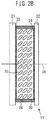
- Figure 2A is a schematic front view of the phase modulating device 11 as viewed from the sample 10, and Figure 2B is a schematic cross-sectional side view of the phase modulating device 11, taken along line AA' in Figure 2A .
- the phase modulating device 11 includes a liquid crystal layer 20 and transparent substrates 21 and 22 disposed along the optical axis OA and substantially parallel to each other on both sides of the liquid crystal layer 20.
- the phase modulating device 11 further includes a transparent electrode 23 disposed between the transparent substrate 21 and the liquid crystal layer 20 and a transparent electrode 24 disposed between the liquid crystal layer 20 and the transparent substrate 22.
- Liquid crystal molecules 25 contained in the liquid crystal layer 20 are sealed between the transparent substrates 21 and 22 by a sealing member 26.
- the liquid crystal layer 20 is chosen to have a thickness, for example, a 10- ⁇ m thickness, that is sufficient to provide a desired phase difference of 0° to 360° between two mutually perpendicular polarization components.
- the transparent substrates 21 and 22 are formed from a material such as glass or resin that is transparent to the illuminating light that the light source 2 emits.
- the transparent electrodes 23 and 24 are formed from a material such as indium tin oxide called ITO.
- the transparent electrodes 23 and 24 are each formed so as to cover the entire active region that drives the liquid crystal molecules 25.
- an alignment film (not depicted) is interposed between the transparent electrode 23 and the liquid crystal layer 20.
- an alignment film (not depicted) is interposed between the transparent electrode 24 and the liquid crystal layer 20.
- a frame (not depicted) for holding the substrates may be placed around the outer peripheries of the substrates, transparent electrodes, and alignment films.
- the liquid crystal molecules 25 contained in the liquid crystal layer 20 are, for example, homogeneously aligned. Then, the liquid crystal molecules 25 are aligned so that their long axes are oriented in a specific direction, for example, the direction indicated by arrow 201, within a plane perpendicular to the optical axis OA.
- the liquid crystal molecules 25 tilt in a direction parallel to the direction of the voltage application in response to the applied voltage.
- the light passing through the liquid crystal layer 20 makes an angle ⁇ with respect to the direction of the long axes of the liquid crystal molecules 25, where ⁇ is the angle that the direction of the long axes make with the direction of the voltage application.
- the refractive index n ⁇ of the liquid crystal molecules for the polarization component parallel to the alignment direction of the liquid crystal molecules 25 is defined by the relation n o ⁇ n ⁇ ⁇ n e , where n o is the refractive index for the polarization component perpendicular to the direction of the long axes of the liquid crystal molecules, and n e is the refractive index for the polarization component parallel to the direction of the long axes of the liquid crystal molecules.
- the beam splitting device 4 can provide a phase difference of 2 ⁇ nd/ ⁇ between the polarization component parallel to the alignment direction of the liquid crystal molecules 25 and the polarization component perpendicular to the alignment direction of the liquid crystal molecules 25.
- ⁇ represents the wavelength of the light passing through the liquid crystal layer 20.
- the alignment direction of the liquid crystal molecules 25 will hereinafter be referred to as the x direction and the direction perpendicular to the alignment direction of the liquid crystal molecules 25 as the y direction.
- the controller 6 stores a mapping table that provides a mapping between the applied voltage and the phase difference resulting between the polarization component in the x direction and the polarization component in the y direction and, by referring to the mapping table, may determine the voltage to be applied to the liquid crystal layer 20 for the desired phase difference.
- the controller 6 can perform control to provide a desired phase difference between the polarization component in the x direction and the polarization component in the y direction by adjusting the voltage to be applied across the liquid crystal layer 20 between the transparent electrodes 23 and 24 according to the wavelength of the light that the light source 2 emits to illuminate the sample 10.
- the controller may store, for each wavelength, a mapping table that provides a mapping between the applied voltage and the phase difference resulting between the polarization component in the x direction and the polarization component in the y direction. Then, by referring to the mapping table for the wavelength used, the controller 6 can appropriately determine the voltage to be applied to the liquid crystal layer 20 for the desired phase difference.
- the controller may store a mapping table that provides a mapping between the applied voltage and the phase difference resulting between the polarization component in the x direction and the polarization component in the y direction. Then, by referring to the mapping table corresponding to the temperature closest to the temperature measured, for example, by a thermometer (not depicted) placed near the phase modulating device 11, the controller 6 can appropriately determine the voltage to be applied to the liquid crystal layer 20 for the desired phase difference.
- the light passed through the phase modulating device 11 enters the birefringent lenses 12-1 and 12-2.
- the birefringent lens 12-1 is a lens that has positive power for the polarization component whose plane of polarization is parallel to the x direction, i.e., the polarization component whose phase is modulated by the phase modulating device 11, but has no power for the polarization component whose plane of polarization is parallel to the y direction.
- the birefringent lens 12-2 is a lens that has no power for the polarization component whose plane of polarization is parallel to the x direction, but has positive power for the polarization component whose plane of polarization is parallel to the y direction.
- the polarization component whose plane of polarization is parallel to the x direction is converted into a convergent beam by the birefringent lens 12-1
- the polarization component whose plane of polarization is parallel to the y direction is converted into a convergent beam by the birefringent lens 12-2.
- the light passed through the phase modulating device 11 is split into two convergent beams by the birefringent lenses 12-1 and 12-2.
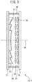
- Figure 3 is a schematic cross-sectional side view of the birefringent lens 12-1, taken in a plane passing through the optical axis OA and parallel to the x direction.
- the birefringent lens 12-1 includes two transparent substrates 31 and 32 arranged substantially parallel to each other, a transparent material layer 33 sandwiched between the transparent substrates 31 and 32 and formed on the surface of the transparent substrate 31 that opposes the transparent substrate 32, and a liquid crystal layer 34 formed between the transparent material layer 33 and the transparent substrate 32.
- the transparent material layer 33 is formed, for example, from a UV curable transparent resin so that a lens surface can be formed along a boundary between it and the liquid crystal layer 34, as will be described later.
- the liquid crystal layer 34 is one example of a birefringent layer whose refractive index differs depending on the plane of polarization of the light passing through the liquid crystal layer 34.
- Liquid crystal molecules 35 are sealed in the liquid crystal layer 34 by a sealing member 36 provided around the liquid crystal layer 34, and are prevented from leaking outside the liquid crystal layer 34.
- the transparent material layer may be provided on the transparent substrate 32 side, and the liquid crystal layer may be provided on the transparent substrate 31 side.
- a Fresnel lens surface 37 with its center on the optical axis OA is formed along the boundary between the transparent material layer 33 and the liquid crystal layer 34 so as to be convex toward the transparent material layer 33.
- the continuous surface between each step on the Fresnel lens surface 37 is formed, for example, as a spherical surface.
- An alignment film for aligning the liquid crystal molecules 35 in a specific direction is formed on both the Fresnel lens surface 37 of the transparent material layer 33 and the surface of the transparent substrate 32 that faces the liquid crystal layer 34.
- the liquid crystal molecules 35 are homogeneously aligned with their long axes oriented parallel to the x direction.
- the alignment direction of the liquid crystal molecules 35 contained in the birefringent lens 12-1 coincides with the alignment direction of the liquid crystal molecules 25 contained in the phase modulating device 11.
- the material of the liquid crystal molecules 35 and the material of the transparent material layer 33 are chosen so that the refractive index for the polarization component in the direction (the y direction) perpendicular to the direction of the long axes of the liquid crystal molecules 35 becomes equal to the refractive index of the transparent material layer 33.
- the Fresnel lens surface 37 has no power for the polarization component whose plane of polarization is parallel to the y direction.
- the Fresnel lens surface 37 has positive power for the polarization component whose plane of polarization is parallel to the x direction. Accordingly, the polarization component whose plane of polarization is parallel to the x direction is converted into a convergent beam by the Fresnel lens surface 37, on the other hand, the polarization component whose plane of polarization is parallel to the y direction is passed unchanged through the Fresnel lens surface 37 and emerges as a parallel beam.
- the birefringent lens 12-2 is substantially identical in structure to the birefringent lens 12-1. However, in the birefringent lens 12-2, the liquid crystal molecules contained in the liquid crystal layer are homogeneously aligned with their long axes oriented parallel to the y direction. As a result, conversely to the case of the birefringent lens 12-1, the polarization component whose plane of polarization is parallel to the y direction is converted into a convergent beam by the Fresnel lens surface in the birefringent lens 12-2, but the birefringent lens 12-2 acts as a parallel plate for the polarization component whose plane of polarization is parallel to the x direction.
- the light passed through the phase modulating device 11 is split into two convergent beams, one being a beam B1 whose plane of polarization is parallel to the x direction and the other a beam B2 whose plane of polarization is parallel to the y direction, by passing through the birefringent lenses 12-1 and 12-2, respectively.
- Both the beams B1 and B2 propagate along the optical axis OA and are converged onto the optical axis OA near the detection surface of the detector 5.
- the birefringent lens 12-1 and the birefringent lens 12-2 may be interchanged in position.
- the material of the transparent material layer and the material of the liquid crystal molecules may be chosen so that the refractive index of the liquid crystal layer for the polarization component in the direction parallel to the direction of the long axes of the liquid crystal molecules becomes equal to the refractive index of the transparent material layer.
- the birefringent lens since the refractive index of the transparent material layer becomes higher than the refractive index of the liquid crystal layer for the polarization component in the direction perpendicular to the direction of the long axes of the liquid crystal molecules, the birefringent lens has positive power, and therefore, the Fresnel lens surface is formed so as to be convex toward the liquid crystal layer.
- each birefringent lens may include, instead of the liquid crystal layer, a birefringent layer formed from a uniaxial birefringent crystal.
- the birefringent crystal need be aligned so that the fast axis of the birefringent crystal is oriented in the x direction in the case of one birefringent lens and in the y direction in the case of the other birefringent lens.
- the material of the birefringent crystal and the material of the transparent material layer are chosen so that the refractive index of the birefringent crystal for the ordinary ray becomes equal to the refractive index of the transparent material layer, and the Fresnel lens surface is formed so as to be convex toward the transparent material layer.
- the material of the birefringent crystal and the material of the transparent material layer may be chosen so that the refractive index of the birefringent crystal for the extraordinary ray becomes equal to the refractive index of the transparent material layer, and the Fresnel lens surface may be formed so as to be convex toward the birefringent layer.
- the convergent beams B1 and B2 enter the polarizing plate 13.
- the polarizing plate 13 allows only a polarization component whose plane of polarization is oriented in a direction that bisects the angle that the x direction makes with the y direction, i.e., whose plane of polarization is oriented 45° with respect to the x direction, to pass through. Accordingly, the convergent beams B1 and B2 passed through the polarizing plate 13 each have a plane of polarization oriented 45° with respect to the x direction, and they interfere with each other.
- the transmission axis of the polarizing plate 13 is oriented along the direction that bisects the angle that the x direction makes with the y direction, the convergent beams B1 and B2 passed through the polarizing plate 13 are substantially equal in intensity, provided that the light from the sample is substantially unpolarized. Since the convergent beams B1 and B2 falling on the detection surface of the detector 5 are substantially equal in intensity, interference fringes with good contrast can be obtained.
- the detector 5 is placed so that the spot size of the convergent beam B1 and the spot size of the convergent beam B2 become substantially equal to each other on the detection surface of the detector 5.
- the overall length of the optical system from the sample to the detector can be reduced, because the two mutually perpendicular polarization components can each be converted into a convergent beam by using a Fresnel lens that can be made to have relatively high power.
- the phase modulating device used in the beam splitting device modulates the phase of the beam by using transparent electrodes uniformly formed across the entire region through which the beam passes, no diffraction occurs due to the transparent electrode structure.
- the beam splitting device can improve the efficiency of light utilization.
- the two beams can be made substantially equal in intensity, the beam splitting device can improve the contrast of the interference fringes.
- each birefringent lens used in the above embodiment may be replaced by a liquid crystal birefringent lens having a plurality of ring-shaped transparent electrodes centered around the optical axis.
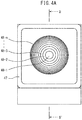
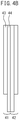
- Figure 4A is a schematic front view of the liquid crystal birefringent lens according to this modified example
- Figure 4B is a schematic side view of the liquid crystal birefringent lens according to this modified example.
- Figure 5 is a schematic cross-sectional side view of the liquid crystal birefringent lens, taken along line BB' in Figure 4A .
- This modified example includes two liquid crystal birefringent lenses 41 and 42.
- the liquid crystal birefringent lens 41 the liquid crystal molecules contained in the liquid crystal layer are homogeneously aligned so that the long axes of the liquid crystal molecules are oriented parallel to the x direction
- the liquid crystal birefringent lens 42 the liquid crystal molecules contained in the liquid crystal layer are homogeneously aligned so that the long axes of the liquid crystal molecules are oriented parallel to the y direction.
- the two liquid crystal birefringent lenses are identical in structure. Therefore, the following description deals only with the liquid crystal birefringent lens 41.
- the liquid crystal birefringent lens 41 includes two transparent substrates 43 and 44 arranged substantially parallel to each other, and a liquid crystal layer 45 sandwiched between the transparent substrates 43 and 44.
- the liquid crystal molecules 46 contained in the liquid crystal layer 45 are prevented from leaking outside the liquid crystal layer 45 by a sealing member 47 provided around the liquid crystal layer 45.
- a plurality of ring-shaped transparent electrodes 48-1 to 48-n formed in concentric fashion with the optical axis OA as a common center are provided on the surface of the transparent substrate 43 that faces the liquid crystal layer 45. Any two adjacent ring-shaped transparent electrodes are spaced a prescribed distance apart and insulated from each other. In Figure 4A , the spacing between each ring-shaped transparent electrode is indicated by a single line for simplicity of illustration. In Figure 5 , only three ring-shaped transparent electrodes are depicted for simplicity of illustration, but a larger number of ring-shaped transparent electrodes may be provided as illustrated in Figure 4A . On the other hand, a transparent electrode 49 is provided on the surface of the transparent substrate 44 that faces the liquid crystal layer 45.
- the ring-shaped transparent electrodes 48-1 to 48-n and the transparent electrode 49 are respectively formed so as to cover the entire active region that drives the liquid crystal molecules 46.
- the ring-shaped transparent electrodes 48-1 to 48-n and the transparent electrode 49 are each connected to the controller 6.
- an alignment film for causing the liquid crystal molecules 46 to align in a specific direction is provided so as to cover the surfaces of the ring-shaped transparent electrodes 48-1 to 48-n that face the liquid crystal layer 45, and a similar alignment film (not depicted) is also formed on the surface of the transparent electrode 49 that faces the liquid crystal layer 45.
- the controller 9 can vary the angle that the liquid crystal molecules 46 sandwiched between any given ring-shaped transparent electrode and the transparent electrode 49 make with the optical axis OA for each of the ring-shaped transparent electrodes 48-1 to 48-n.
- the refractive index of the liquid crystal layer between any given ring-shaped transparent electrode and the transparent electrode 49 for the polarization component parallel to the x direction can be varied for each of the ring-shaped transparent electrodes 48-1 to 48-n.
- the controller applies a voltage between each of the ring-shaped transparent electrodes 48-1 to 48-n and the transparent electrode 49 so that the refractive index of the liquid crystal layer 46 for the polarization component parallel to the x direction decreases with increasing distance from the optical axis OA.
- the liquid crystal birefringent lens 41 functions as a GRIN lens having positive power for the polarization component parallel to the x direction, and can convert the polarization component parallel to the x direction into a convergent beam.
- the controller 6 can make the liquid crystal birefringent lens 42 function as a GRIN lens having positive power for the polarization component parallel to the y direction.
- the incident beam can be split into two convergent beams one for each of the two polarization components by passing through the two liquid crystal birefringent lenses 41 and 42.
- the beam splitting device may include only one birefringent lens.
- the beam with one or the other of the polarization components is passed unchanged through the beam splitting device and emerges as a parallel beam.
- interference fringes similar to those generated by the device disclosed in non-patent document 1 are formed on the detection surface of the detector 5.
- the beam splitting device according to the second embodiment differs from the beam splitting device according to the first embodiment in that only one birefringent lens is provided and in that the relationship between the refractive index of the transparent material layer of the birefringent lens and the refractive index of the liquid crystal layer is different. The following description will therefore be given by dealing with the birefringent lens.
- FIG. 6 is a diagram schematically illustrating the construction of a hologram generating apparatus incorporating the beam splitting device according to the second embodiment of the present invention.
- the hologram generating apparatus 1 includes a light source 2, a collimator 3, the beam splitting device 4, a detector 5, and a controller 6.
- the component elements of the hologram generating apparatus 1 are identified by the same reference numerals as those used to designate the corresponding component elements in Figure 1 .
- the birefringent lens 12 contained in the beam splitting device 4 may be made identical in structure to the birefringent lens 12-1 contained in the beam splitting device 4 of the first embodiment, except that the relationship between the refractive index of the transparent material layer and the refractive index of the liquid crystal layer is different. Therefore, for the description of the birefringent lens 12, refer to the description previously given with reference to Figure 3 .
- the liquid crystal molecules 35 contained in the liquid crystal layer 34 of the birefringent lens 12 are homogeneously aligned so that the long axes of the liquid crystal molecules 35 are oriented parallel to the x direction or y direction.
- the material of the transparent material layer 33 and the material of the liquid crystal molecules are chosen so that the refractive index of the transparent material layer 33 become lower than the refractive index of the liquid crystal layer 34 for the polarization component perpendicular to the direction of the long axes of the liquid crystal molecules 35 contained in the liquid crystal layer 34.
- the Fresnel lens surface formed along the boundary between the transparent material layer 33 and the liquid crystal layer 34 so as to be convex toward the transparent material layer 33 has positive power for both the polarization component in the x direction and the polarization component in the y direction.
- the power that the Fresnel lens surface has on the polarization component in the x direction is different from the power that the Fresnel lens surface has on the polarization component in the y direction.
- the beam passing through the birefringent lens 12 is split into two beams, the convergent beam B1 having the polarization component in the x direction and the convergent beam B2 having the polarization component in the y direction.
- the material of the transparent material layer 33 and the material of the liquid crystal molecules may be chosen so that the refractive index of the transparent material layer 33 become higher than the refractive index of the liquid crystal layer 34 for the polarization component parallel to the direction of the long axes of the liquid crystal molecules 35 contained in the liquid crystal layer 34.
- the Fresnel lens surface is formed so as to be convex toward the liquid crystal layer 34.
- the beam splitting device of this embodiment can further improve the efficiency of light utilization.
- the birefringent lens in each of the above embodiments may include two transparent electrodes disposed opposite each other across the liquid crystal layer.
- one transparent electrode 38 is disposed on the surface of the Fresnel lens surface 37 of the transparent material layer 33, and the other transparent electrode 39 is disposed on the surface of the transparent substrate 32 that faces the liquid crystal layer.
- the controller 6 can maintain the difference between the refractive index of the liquid crystal layer and the refractive index of the transparent material layer constant regardless of the wavelength, and as a result, can maintain the power at the Fresnel lens surface at a constant level. Consequently, according to this modified example, each convergent beam can always be converged on the same position, regardless of the wavelength of the light emitted from the light source 2.
- the hologram generating apparatus incorporating the beam splitting device according to any one of the above embodiments or their modified examples can also be used as a holographic microscope by generating a hologram of the original sample in enlarged form.
- the hologram generating apparatus incorporating the beam splitting device according to any one of the above embodiments or their modified examples may be configured to be switchable between a hologram mode in which a hologram of a sample is generated in the manner described above and a focus mode in which an image of the sample is generated by focusing the image on the detector.
- Figure 7A is a diagram illustrating the case in which the hologram generating apparatus incorporating the beam splitting device according to any one of the embodiments of the present invention or their modified examples is used in the hologram mode.
- Figure 7B is a diagram illustrating the case in which the hologram generating apparatus incorporating the beam splitting device according to any one of the embodiments of the present invention or their modified examples is used in the focus mode.
- the component elements of the hologram generating apparatus are identified by the same reference numerals as those used to designate the corresponding component elements of the hologram generating apparatus in Figure 1 .
- the controller and the light source are omitted from illustration for simplicity.
- the birefringent lenses 12'-1 and 12'-2 contained in the beam splitting device 4 differ from the birefringent lenses 12-1 and 12-2 illustrated in Figure 1 in that two transparent electrodes opposite each other across the liquid crystal layer, as indicated by dashed lines in Figure 3 , are added so that the lens power can be adjusted.
- the birefringent lenses 12'-1 and 12'-2 use may be made of the liquid crystal birefringent lenses 41 and 42 depicted in Figures 4A , 4B , and 5 .
- the polarization component parallel to the x direction is converted into the convergent beam B1 by the birefringent lens 12'-1.
- the polarization component parallel to the y direction perpendicular to the x direction is converted into the convergent beam B2 by the birefringent lens 12'-2.
- the refractive index of the liquid crystal layer varies according to the voltage applied between the two transparent electrodes sandwiching the liquid crystal layer; in view of this, the power of each of the birefringent lenses 12'-1 and 12'-2 is varied by adjusting the corresponding voltage.
- the voltage to be applied between the two transparent electrodes sandwiching the liquid crystal layer in the birefringent lens 12'-1 and the voltage to be applied between the two transparent electrodes sandwiching the liquid crystal layer in the birefringent lens 12'-2 are adjusted so that the spot size of the convergent beam B1 and the spot size of the convergent beam B2 become substantially equal to each other on the detection surface of the detector 5.
- the voltage to be applied between the two transparent electrodes sandwiching the liquid crystal layer in the birefringent lens 12'-1 is adjusted so that the convergent beam B1 is focused on the detection surface of the detector 5, i.e., the spot size of the convergent beam B1 becomes the smallest on the detection surface of the detector 5.
- the voltage to be applied between the two transparent electrodes sandwiching the liquid crystal layer in the birefringent lens 12'-2 is adjusted so that the convergent beam B2 is focused on the detection surface of the detector 5, i.e., the spot size of the convergent beam B2 becomes the smallest on the detection surface of the detector 5.
- the hologram generating apparatus incorporating the beam splitting device according to any one of the above embodiments or their modified examples can be switched between the hologram mode and the focus mode by just adjusting the voltage to be applied to the liquid crystal layer in each birefringent lens of the beam splitting device. There is therefore no need to mechanically move each corresponding component element of the hologram generating apparatus in order to switch it between the hologram mode and the focus mode.
- This not only serves to simplify the construction of the hologram generating apparatus, but also serves to prevent any component element from moving out of alignment when switching is made between the hologram mode and the focus mode.
- the beam splitting device may include a bulk lens in addition to the birefringent lenses.
- Figure 8A is a diagram illustrating the case in which the hologram generating apparatus incorporating the beam splitting device having a bulk lens is used in the hologram mode.
- Figure 8B is a diagram illustrating the case in which the hologram generating apparatus incorporating the beam splitting device having a bulk lens is used in the focus mode.
- the component elements of the hologram generating apparatus are identified by the same reference numerals as those used to designate the corresponding component elements of the hologram generating apparatus in Figure 1 .
- the controller and the light source are omitted from illustration for simplicity.
- a bulk lens 14 having positive power is interposed between the birefringent lens 12"-2 and the polarizing plate 13.
- the bulk lens 14 may be interposed between the polarizing plate 13 and the detector 5.
- the birefringent lenses 12"-1 and 12"-2 contained in the beam splitting device 4 differ from the birefringent lenses 12-1 and 12-2 illustrated in Figure 1 in that two transparent electrodes opposite each other across the liquid crystal layer, as indicated by dashed lines in Figure 3 , are added so that the lens power can be adjusted.
- the birefringent lens 12"-1, 12"-2 when no voltage is applied between the two transparent electrodes sandwiching the liquid crystal layer, the birefringent lens 12"-1, 12"-2 does not have any power, and when voltage is applied, the liquid crystal molecules in the liquid crystal layer are aligned vertically in a direction substantially parallel to the optical axis so that the birefringent lens 12"-1, 12"-2 has power for the polarization component parallel to the direction of the long axes of the liquid crystal molecules.
- the direction of the long axes of the liquid crystal molecules is brought closer to the direction parallel to a plane perpendicular to the optical axis, as a result of which the refractive index of the liquid crystal layer for the polarization component parallel to the direction of the long axes of the liquid crystal molecules increases, and thus the birefringent lens 12"-1, 12"-2 has power.
- the material of the transparent material layer and the material of the liquid crystal molecules contained in the liquid crystal layer are chosen so that, when no voltage is applied between the two transparent electrodes sandwiching the liquid crystal layer, the birefringent lens 12"-1 does not have any power not only for the polarization component parallel to the x direction but also for the polarization component parallel to the y direction.
- the material of the transparent material layer 33 and the material of the liquid crystal molecules contained in the liquid crystal layer 34 are chosen so that, when no voltage is applied between the two transparent electrodes sandwiching the liquid crystal layer 34, the birefringent lens 12"-2 does not have any power not only for the polarization component parallel to the x direction but also for the polarization component parallel to the y direction. Accordingly, in each of the birefringent lenses 12"-1 and 12"-2, when no voltage is applied between the two transparent electrodes sandwiching the liquid crystal layer, the beam passing through the beam splitting device 4 is not split.
- the power of the bulk lens 14 is set so that, when no voltage is applied between the two transparent electrodes sandwiching the liquid crystal layer in each of the birefringent lenses 12"-1 and 12"-2, the beam B passed through the beam splitting device 4 is focused on the detection surface of the detector 5.
- the Fresnel lens surface 37 formed along the boundary between the transparent material layer 33 and the liquid crystal layer 34 is set so that the birefringent lens 12"-2 will have negative power by adjusting the voltage to be applied between the two transparent electrodes sandwiching the liquid crystal layer 34.
- the Fresnel lens surface 37 is formed so as to be convex toward the liquid crystal layer 34.
- the birefringent lens 12"-1 has positive power for the polarization component parallel to the x direction when voltage is applied between the two transparent electrodes sandwiching the liquid crystal layer in the birefringent lens 12"-1.
- the beam B1 whose plane of polarization is parallel to the x direction is focused forwardly of the detection surface of the detector 5 (i.e., at a position nearer to the beam splitting device 4).
- the birefringent lens 12"-2 has negative power for the polarization component parallel to the y direction.
- the beam B2 whose plane of polarization is parallel to the y direction is focused rearwardly of the detection surface of the detector 5. Accordingly, the voltage to be applied between the two transparent electrodes sandwiching the liquid crystal layer in the birefringent lens 12"-1 and the voltage to be applied between the two transparent electrodes sandwiching the liquid crystal layer in the birefringent lens 12"-2 need only be adjusted so that the spot size of the beam B1 and the spot size of the beam B2 become substantially equal to each other on the detection surface of the detector 5.
- the bulk lens can be designed to provide part of the power needed to converge the light passing through the beam splitting device, the power of each birefringent lens can be reduced correspondingly. Furthermore, in this modified example, when using the hologram generating apparatus in the focus mode, since there is no need to apply voltage to the liquid crystal layer in each birefringent lens the power consumption of the hologram generating apparatus can be reduced.
- the liquid crystal molecules contained in the liquid crystal layer in each of the birefringent lenses 12"-1 and 12"-2 may be aligned so that the long axes of the liquid crystal molecules are oriented substantially parallel to the plane perpendicular to the optical axis.
- each of the birefringent lenses 12"-1 and 12"-2 has power. Accordingly, when using the hologram generating apparatus in the hologram mode, the controller need not apply any voltage between the two transparent electrodes sandwiching the liquid crystal layer in each of the birefringent lenses 12"-1 and 12"-2.
- the controller when using the hologram generating apparatus in the focus mode, the controller only needs to apply voltage between the two transparent electrodes sandwiching the liquid crystal layer in each of the birefringent lenses 12"-1 and 12"-2 until the birefringent lenses 12"-1 and 12"-2 no longer have power.
- each birefringent lens may be formed so that, when using the hologram generating apparatus in the hologram mode, the birefringent lens 12"-1 has negative power and the birefringent lens 12"-2 has positive power.
- the liquid crystal birefringent lenses 41 and 42 depicted in Figures 4A , 4B , and 5 may be used instead of the birefringent lenses 12"-1 and 12"-2.
- the refractive index of the liquid crystal layer also varies with the wavelength of the light passing through it. Accordingly, the power of each of the birefringent lenses 12"-1 and 12"-2 also varies with the wavelength of the light incident on the lens. For example, the shorter the wavelength of the incident light, the larger the refractive index of the liquid crystal layer, and thus the larger is the power of each of the birefringent lenses 12"-1 and 12"-2.
- the focusing position of the beam B1 having the polarization component parallel to the x direction and the focusing position of the beam B2 having the polarization component parallel to the y direction each vary depending on the wavelength of the light incident on the corresponding lens.
- the birefringent lens 12"-1 has positive power for the polarization component parallel to the x direction
- the birefringent lens 12"-2 has negative power for the polarization component parallel to the y direction.
- the beams B1 and B2 are beams respectively represented by solid lines.
- the wavelength of the light entering the beam splitting device 4 is ⁇ 2 which is shorter than ⁇ 1
- the beams B1 and B2 are shifted as indicated by dashed lines.
- the detector 5 need only be arranged so that the detection surface of the detector 5 is located at the position at which the spot size of the beam B1 and the spot size of the beam B2 become substantially equal to each other regardless of the wavelength; then, the spot sizes of the beams B1 and B2 always become substantially equal to each other on the detection surface of the detector 5, regardless of the wavelength, though the spot sizes of the beams B1 and B2 both become larger or smaller depending on the wavelength. Accordingly, regardless of the wavelength of the light that the light source emits, the hologram generating apparatus can generate an appropriate hologram without having to adjust the voltage to be applied to the liquid crystal layer in each birefringent lens according to the wavelength.
- the hologram generating apparatus can generate an appropriate hologram without having to adjust the voltage to be applied to the liquid crystal layer in each birefringent lens.
- the transparent electrodes sandwiching the liquid crystal layer may be omitted from each of the birefringent lenses 12"-1 and 12"-2, if the hologram generating apparatus is not used in the focus mode.
- the material of the liquid crystal molecules and the material forming the transparent material layer in each birefringent lens are chosen so that when no voltage is applied to the liquid crystal layer, the birefringent lenses 12"-1 and 12"-2 have positive power and negative power, respectively.
- each birefringent lens could be formed in the shape of a kinoform so that the Fresnel lens surface could be made to function as a diffractive lens.
- each birefringent lens were provided with two transparent electrodes on both sides of the liquid crystal layer in order to switch the hologram generating apparatus between the focus mode and the hologram mode, it would be difficult to keep the focusing positions of the beams B1 and B2 unchanged regardless of the wavelength of the incident light by adjusting the voltage to be applied to the liquid crystal layer according to the wavelength of the incident light.
- the hologram generating apparatus illustrated in Figures 8A and 8B even if the wavelength of the incident light changes, the spot size of the beam B1 and the spot size of the beam B2 can be made substantially equal to each other on the detection surface of the detector 5 without having to adjust the voltage to be applied to the liquid crystal layer in each birefringent lens. Accordingly, the hologram generating apparatus illustrated in Figures 8A and 8B is also advantageous when the Fresnel lens surface of each birefringent lens is made to function as a diffractive lens.
Landscapes
- Physics & Mathematics (AREA)
- General Physics & Mathematics (AREA)
- Nonlinear Science (AREA)
- Optics & Photonics (AREA)
- Crystallography & Structural Chemistry (AREA)
- Chemical & Material Sciences (AREA)
- Mathematical Physics (AREA)
- Engineering & Computer Science (AREA)
- Computing Systems (AREA)
- Theoretical Computer Science (AREA)
- Liquid Crystal (AREA)
- Holo Graphy (AREA)
- Polarising Elements (AREA)
Claims (4)
- Strahlteilungseinrichtung zum Aufzeichnen von In-Line-Hologrammen, umfassend:eine Phasenmodulationseinrichtung (11), die eine Phasendifferenz bereitstellt zwischen einer ersten Polarisationskomponente, die in Einfallslicht enthalten ist und eine Polarisationsebene parallel zu einer ersten Richtung aufweist, und einer zweiten Polarisationskomponente, die im Einfallslicht enthalten ist und eine Polarisationsebene parallel zu einer zweiten Richtung, die senkrecht zur ersten Richtung liegt, aufweist;mindestens eine Doppelbrechungslinse (12, 12-1, 12-2, 41, 42), die das Einfallslicht in einen ersten Strahl mit der ersten Polarisationskomponente und einen zweiten Strahl mit der zweiten Polarisationskomponente aufspaltet und die bewirkt, dass sowohl der erste Strahl wie der zweite Strahl entlang einer gemeinsamen optischen Achse austreten, und den ersten und/oder den zweiten Strahl in konvergentes Licht umwandelt, undeine Polarisatorplatte (13), die hinter der mindestens einen Doppelbrechungslinse gelegen ist und die im gemeinsamen Strahlengang des ersten und des zweiten Strahls angeordnet ist, so dass ein Durchtritt einer Polarisationskomponente parallel in einer Richtung, die einen Winkel halbiert, den die erste Richtung mit der zweiten Richtung einschließt, ermöglicht ist,wobei die Phasenmodulationseinrichtung (11) eine Flüssigkristallschicht (20), die Flüssigkristallmoleküle (25) enthält und die so ausgerichtet ist, dass lange Achsen der Flüssigkristallmoleküle in die erste Richtung orientiert sind, und zwei transparente Elektroden (23, 24) aufweist, die durch sandwichartiges Anordnen der Flüssigkristallschicht (20) dazwischen einander gegenüberliegend angeordnet sind, undwobei die Phasenmodulationseinrichtung (11) eine Phase der ersten Polarisationskomponente gemäß einer zwischen den beiden transparenten Elektroden (23, 24) angelegten Spannung verschiebt, so dass eine Phasendifferenz zwischen der ersten Polarisationskomponente und der zweiten Polarisationskomponente auftritt.
- Strahlteilungseinrichtung nach Anspruch 1, wobei die mindestens eine Doppelbrechungslinse eine erste Doppelbrechungslinse (12-1) und eine zweite Doppelbrechungslinse (12-2) aufweist, die entlang der optischen Achse angeordnet sind, und wobei:die erste Doppelbrechungslinse (12-1) eine doppelbrechende Schicht (34), die einen ersten Brechungsindex für die erste Polarisationskomponente und einen zweiten Brechungsindex für die zweite Polarisationskomponente aufweist, und eine transparente Materialschicht (33) enthält, die den zweiten Brechungsindex aufweist, wobei die doppelbrechende Schicht und die transparente Materialschicht entlang der optischen Achse so angeordnet sind, dass dazwischen eine Linsenfläche ausgebildet ist, die eine Linsenstärke für die erste Polarisationskomponente aufweist; unddie zweite Doppelbrechungslinse (12-2) eine doppelbrechende Schicht, die einen dritten Brechungsindex für die erste Polarisationskomponente und einen vierten Brechungsindex für die zweite Polarisationskomponente aufweist, und eine transparente Materialschicht enthält, die den dritten Brechungsindex aufweist, wobei die doppelbrechende Schicht und die transparente Materialschicht entlang der optischen Achse so angeordnet sind, dass dazwischen eine Linsenfläche ausgebildet ist, die eine Linsenstärke für die zweite Polarisationskomponente aufweist.
- Strahlteilungseinrichtung nach Anspruch 2, wobei die erste Doppelbrechungslinse (12'-1, 12"-1) weiter zwei transparente Elektroden (38, 39) aufweist, die durch sandwichartiges Anordnen der doppelbrechenden Schicht (34) dazwischen einander gegenüberliegend angeordnet sind, und wobei die doppelbrechende Schicht (34) der ersten Doppelbrechungslinse als Flüssigkristallschicht ausgebildet ist, die Flüssigkristallmoleküle enthält und die so ausgerichtet ist, dass lange Achsen der Flüssigkristallmoleküle in eine Richtung parallel zur ersten Polarisationskomponente orientiert sind, und
die erste Doppelbrechungslinse (12'-1, 12"-1) ihre Linsenstärke für die erste Polarisationskomponente durch Verändern des ersten Brechungsindex gemäß einer zwischen den beiden transparenten Elektroden (38, 39) angelegten Spannung verändert. - Strahlteilungseinrichtung nach Anspruch 1, wobei die mindestens eine Doppelbrechungslinse (12) aus einer einzigen Doppelbrechungslinse besteht und eine doppelbrechende Schicht (34), die eine ersten Brechungsindex für die erste Polarisationskomponente und einen zweiten Brechungsindex für die zweite Polarisationskomponente aufweist, und eine transparente Materialschicht (33) enthält, die einen dritten Brechungsindex aufweist, wobei die doppelbrechende Schicht (34) und die transparente Materialschicht (33) entlang der optischen Achse so angeordnet sind, dass dazwischen eine Linsenfläche ausgebildet ist, die eine erste Linsenstärke für die erste Polarisationskomponente und eine zweite Linsenstärke für die zweite Polarisationskomponente aufweist.
Applications Claiming Priority (2)
| Application Number | Priority Date | Filing Date | Title |
|---|---|---|---|
| JP2013041000 | 2013-03-01 | ||
| PCT/JP2014/052946 WO2014132781A1 (ja) | 2013-03-01 | 2014-02-07 | 光束分割素子 |
Publications (3)
| Publication Number | Publication Date |
|---|---|
| EP2963503A1 EP2963503A1 (de) | 2016-01-06 |
| EP2963503A4 EP2963503A4 (de) | 2016-08-10 |
| EP2963503B1 true EP2963503B1 (de) | 2020-05-20 |
Family
ID=51428055
Family Applications (1)
| Application Number | Title | Priority Date | Filing Date |
|---|---|---|---|
| EP14757203.6A Active EP2963503B1 (de) | 2013-03-01 | 2014-02-07 | Lichtstromteilungselement |
Country Status (5)
| Country | Link |
|---|---|
| US (1) | US20160011564A1 (de) |
| EP (1) | EP2963503B1 (de) |
| JP (1) | JP6345170B2 (de) |
| CN (1) | CN105009002B (de) |
| WO (1) | WO2014132781A1 (de) |
Families Citing this family (38)
| Publication number | Priority date | Publication date | Assignee | Title |
|---|---|---|---|---|
| US10120112B2 (en) | 2010-01-29 | 2018-11-06 | Beam Engineering For Advanced Measurements Co. | Diffractive waveplate lenses for correcting aberrations and polarization-independent functionality |
| US11366254B2 (en) | 2010-01-29 | 2022-06-21 | Beam Engineering For Advanced Measurements Co. | High-efficiency wide-angle beam steering system |
| US10114239B2 (en) | 2010-04-21 | 2018-10-30 | Beam Engineering For Advanced Measurements Co. | Waveplate lenses and methods for their fabrication |
| US10197715B1 (en) | 2013-03-15 | 2019-02-05 | Beam Engineering For Advanced Measurements Co. | Methods of diffractive lens and mirror fabrication |
| US10185182B2 (en) | 2013-03-03 | 2019-01-22 | Beam Engineering For Advanced Measurements Co. | Mechanical rubbing method for fabricating cycloidal diffractive waveplates |
| JP6416270B2 (ja) * | 2013-10-03 | 2018-10-31 | セルオプティック、インコーポレイテッドCelloptic, Inc. | 透過型液晶レンズを使用するインコヒーレント蛍光デジタルホログラフィック顕微鏡法 |
| US10289070B2 (en) | 2014-05-01 | 2019-05-14 | Cell-Optic, Inc. | Holograms using birefringent lenses |
| US10591870B2 (en) | 2014-05-01 | 2020-03-17 | Celloptic, Inc. | Birefringent lens interferometer for use in microscopy and other applications |
| US10423123B2 (en) | 2014-05-01 | 2019-09-24 | Celloptic, Inc. | System, apparatus and method for using birefringent lenses to create holograms from received electromagnetic radiation |
| WO2017070159A1 (en) * | 2015-10-19 | 2017-04-27 | The Regents Of The University Of California | Optical phase modulation systems and methods |
| US10436957B2 (en) | 2015-10-27 | 2019-10-08 | Beam Engineering For Advanced Measurements Co. | Broadband imaging with diffractive waveplate coated mirrors and diffractive waveplate objective lens |
| US10437129B2 (en) * | 2015-11-10 | 2019-10-08 | Verily Life Sciences Llc | Dynamic diffractive liquid crystal lens |
| JP2019511743A (ja) * | 2016-03-10 | 2019-04-25 | セルオプティック、インコーポレイテッドCelloptic, Inc. | 複屈折レンズ干渉計 |
| JP2019515354A (ja) * | 2016-05-06 | 2019-06-06 | セルオプティック、インコーポレイテッドCelloptic, Inc. | 顕微鏡法及び他の応用例で使用するための複屈折レンズ干渉計 |
| US10795315B2 (en) * | 2016-05-11 | 2020-10-06 | The Regents Of The University Of California | Method and system for pixel super-resolution of multiplexed holographic color images |
| CN106226930B (zh) * | 2016-09-08 | 2023-06-20 | 京东方科技集团股份有限公司 | 一种菲涅尔透镜装置 |
| US10423045B2 (en) | 2016-11-14 | 2019-09-24 | Beam Engineering For Advanced Measurements Co. | Electro-optical diffractive waveplate beam shaping system |
| US10698235B2 (en) * | 2017-02-16 | 2020-06-30 | Verily Life Sciences Llc | Ophthalmic device including liquid crystal alignment features |
| CN106842598B (zh) * | 2017-03-17 | 2019-09-06 | 京东方科技集团股份有限公司 | 显示切换装置、显示器和电子设备 |
| US10274805B2 (en) | 2017-06-13 | 2019-04-30 | Beam Engineering For Advanced Measurements Co. | Polarization-independent switchable lens system |
| EP3447567B1 (de) * | 2017-08-24 | 2023-07-12 | Morrow N.V. | Optische vorrichtung mit flüssigkristallausrichtung |
| CZ2017570A3 (cs) * | 2017-09-21 | 2018-11-07 | Vysoké Učení Technické V Brně | Zobrazovací modul pro mimoosový záznam polarizačně oddělených vln |
| US11982906B1 (en) | 2018-03-05 | 2024-05-14 | Beam Engineering For Advanced Measurements Co. | Polarization-independent diffractive optical structures |
| US11175441B1 (en) | 2018-03-05 | 2021-11-16 | Beam Engineering For Advanced Measurements Co. | Polarization-independent diffractive optical structures |
| JP6995975B2 (ja) * | 2018-03-12 | 2022-02-04 | 富士フイルム株式会社 | 判定方法 |
| EP3807715A4 (de) * | 2018-06-15 | 2022-03-23 | Magic Leap, Inc. | Polarisationsschalter mit breitem sichtfeld und optischen flüssigkristallelementen mit vorneigung |
| EP3807711A4 (de) | 2018-06-15 | 2022-02-23 | Magic Leap, Inc. | Polarisationsschalter mit breitem sichtfeld und verfahren zur herstellung von optischen flüssigkristallelementen mit vorneigung |
| GB201810565D0 (en) | 2018-06-27 | 2018-08-15 | Univ Leeds Innovations Ltd | Improvements in and relating to optical elements |
| US11126055B2 (en) | 2018-07-10 | 2021-09-21 | Verily Life Sciences Llc | Switching of liquid crystal device |
| US10802382B2 (en) * | 2018-07-24 | 2020-10-13 | Qualcomm Incorporated | Adjustable light projector for flood illumination and active depth sensing |
| US11144010B2 (en) * | 2018-08-10 | 2021-10-12 | Samsung Electronics Co., Ltd. | Focus modulation optical system and holographic display device having the same |
| CN109507820A (zh) * | 2018-12-21 | 2019-03-22 | 江苏慧光电子科技有限公司 | 一种空间光调制器 |
| CN109557702B (zh) * | 2018-12-25 | 2022-04-08 | 江苏慧光电子科技有限公司 | 光电扫描器 |
| US11294240B2 (en) | 2019-08-10 | 2022-04-05 | Beam Engineering For Advanced Measurements Co. | Diffractive waveplate devices that operate over a wide temperature range |
| JP7432227B2 (ja) * | 2020-02-27 | 2024-02-16 | 国立大学法人 東京大学 | 位相イメージング装置、位相イメージング方法 |
| US11442332B1 (en) * | 2020-10-26 | 2022-09-13 | Amazon Technologies, Inc. | Tunable liquid crystal lens with electrically tunable axis of astigmatism |
| JP7541932B2 (ja) | 2021-01-07 | 2024-08-29 | 日本放送協会 | インコヒーレントディジタルホログラム用撮像光学系およびそれを用いた撮像装置 |
| CN114764197A (zh) * | 2021-01-13 | 2022-07-19 | 京东方科技集团股份有限公司 | 一种显示器件、显示装置及显示方法 |
Family Cites Families (11)
| Publication number | Priority date | Publication date | Assignee | Title |
|---|---|---|---|---|
| JP3452113B2 (ja) * | 1996-08-30 | 2003-09-29 | ソニー株式会社 | 光情報記録装置および方法、光情報再生装置および方法ならびに光情報記録媒体 |
| JPH11133842A (ja) * | 1997-10-24 | 1999-05-21 | Sony Corp | 光情報記録装置、光情報再生装置および光情報記録媒体 |
| CN100492505C (zh) * | 2004-02-03 | 2009-05-27 | 旭硝子株式会社 | 液晶透镜元件及光学头装置 |
| KR20060126668A (ko) * | 2004-02-03 | 2006-12-08 | 아사히 가라스 가부시키가이샤 | 액정 렌즈 소자 및 광헤드 장치 |
| JP4692489B2 (ja) * | 2004-10-19 | 2011-06-01 | 旭硝子株式会社 | 液晶回折レンズ素子および光ヘッド装置 |
| US8537310B2 (en) * | 2005-03-01 | 2013-09-17 | North Carolina State University | Polarization-independent liquid crystal display devices including multiple polarization grating arrangements and related devices |
| JPWO2006115147A1 (ja) * | 2005-04-25 | 2008-12-18 | 旭硝子株式会社 | 撮像レンズ |
| KR101241770B1 (ko) * | 2006-02-17 | 2013-03-14 | 삼성디스플레이 주식회사 | 입체영상 변환패널 및 이를 갖는 입체영상 표시장치 |
| US8009340B2 (en) | 2007-01-30 | 2011-08-30 | Celloptic, Inc. | Apparatus and method for recording fresnel holograms |
| JP5651595B2 (ja) * | 2008-10-09 | 2015-01-14 | ノース・キャロライナ・ステイト・ユニヴァーシティ | 複数の偏光回折格子配置を有する偏光無依存型液晶ディスプレイ装置及び関連装置 |
| DE112011104705T5 (de) * | 2011-01-12 | 2013-10-31 | Arisawa Mfg. Co., Ltd. | Stereoskopische Bildanzeigevorrichtung |
-
2014
- 2014-02-07 WO PCT/JP2014/052946 patent/WO2014132781A1/ja active Application Filing
- 2014-02-07 US US14/771,784 patent/US20160011564A1/en not_active Abandoned
- 2014-02-07 CN CN201480012264.7A patent/CN105009002B/zh not_active Expired - Fee Related
- 2014-02-07 EP EP14757203.6A patent/EP2963503B1/de active Active
- 2014-02-07 JP JP2015502843A patent/JP6345170B2/ja not_active Expired - Fee Related
Non-Patent Citations (1)
| Title |
|---|
| A. W. LOHMANN: "Wavefront Reconstruction for Incoherent Objects", JOURNAL OF THE OPTICAL SOCIETY OF AMERICA, vol. 55, no. 11, 1 November 1965 (1965-11-01), US, pages 1555_1, XP055443774, ISSN: 0030-3941, DOI: 10.1364/JOSA.55.1555_1 * |
Also Published As
| Publication number | Publication date |
|---|---|
| US20160011564A1 (en) | 2016-01-14 |
| CN105009002B (zh) | 2019-03-05 |
| JPWO2014132781A1 (ja) | 2017-02-02 |
| JP6345170B2 (ja) | 2018-06-20 |
| EP2963503A4 (de) | 2016-08-10 |
| CN105009002A (zh) | 2015-10-28 |
| WO2014132781A1 (ja) | 2014-09-04 |
| EP2963503A1 (de) | 2016-01-06 |
Similar Documents
| Publication | Publication Date | Title |
|---|---|---|
| EP2963503B1 (de) | Lichtstromteilungselement | |
| US20220075242A1 (en) | Compact Edge Illuminated Diffractive Display | |
| US11747719B2 (en) | Diffractive waveguide providing structured illumination for object detection | |
| US9772484B2 (en) | Light modulating device | |
| US10523926B2 (en) | Backlight unit and holographic display including the same | |
| JP3799773B2 (ja) | 光ビームの制御システム | |
| CN105917277B (zh) | 用于全息重建的显示设备 | |
| JP2022091982A (ja) | 均一出力照明を有する導波管 | |
| US9075184B2 (en) | Compact edge illuminated diffractive display | |
| TWI540287B (zh) | The direct view shows the light emitting unit | |
| KR101075351B1 (ko) | 홀로그램 기록 장치 | |
| GB2496108A (en) | Image colour frequency-based pixel number allocation | |
| CN110865497A (zh) | 焦距调制光学系统和具有其的全息显示装置 | |
| US20150160614A1 (en) | Complex spatial light modulator and three-dimensional image display apparatus having the same | |
| TWI464457B (zh) | 數位全像顯示裝置 | |
| KR20150000351A (ko) | 광학적 어드레싱 공간 광변조기 기반 홀로그래픽 디스플레이 | |
| JP2023008330A (ja) | ホログラフィ用再生照明光照射装置およびホログラフィックディスプレイ | |
| WO2015141336A1 (ja) | 光学デバイス | |
| WO2022209518A1 (ja) | 干渉光生成素子およびホログラム記録装置 | |
| KR102268291B1 (ko) | 영상 표시장치 | |
| CN116547597A (zh) | 具有fLCOS显示面板的光学系统 | |
| KR20230078580A (ko) | 복굴절 셀 | |
| JPH05173169A (ja) | 光書き込み型空間光変調器及び光相関器 | |
| KR20120069463A (ko) | 2차원 및 3차원의 모드 전환이 가능한 영상장치 | |
| JPH03264918A (ja) | 反射型位相変調素子および光情報処理装置 |
Legal Events
| Date | Code | Title | Description |
|---|---|---|---|
| PUAI | Public reference made under article 153(3) epc to a published international application that has entered the european phase |
Free format text: ORIGINAL CODE: 0009012 |
|
| 17P | Request for examination filed |
Effective date: 20150827 |
|
| AK | Designated contracting states |
Kind code of ref document: A1 Designated state(s): AL AT BE BG CH CY CZ DE DK EE ES FI FR GB GR HR HU IE IS IT LI LT LU LV MC MK MT NL NO PL PT RO RS SE SI SK SM TR |
|
| AX | Request for extension of the european patent |
Extension state: BA ME |
|
| DAX | Request for extension of the european patent (deleted) | ||
| A4 | Supplementary search report drawn up and despatched |
Effective date: 20160708 |
|
| RIC1 | Information provided on ipc code assigned before grant |
Ipc: G03H 1/04 20060101AFI20160704BHEP Ipc: G02B 5/30 20060101ALI20160704BHEP Ipc: G02F 1/13 20060101ALI20160704BHEP |
|
| RAP1 | Party data changed (applicant data changed or rights of an application transferred) |
Owner name: CITIZEN WATCH CO., LTD. |
|
| GRAP | Despatch of communication of intention to grant a patent |
Free format text: ORIGINAL CODE: EPIDOSNIGR1 |
|
| STAA | Information on the status of an ep patent application or granted ep patent |
Free format text: STATUS: GRANT OF PATENT IS INTENDED |
|
| INTG | Intention to grant announced |
Effective date: 20191202 |
|
| GRAS | Grant fee paid |
Free format text: ORIGINAL CODE: EPIDOSNIGR3 |
|
| GRAA | (expected) grant |
Free format text: ORIGINAL CODE: 0009210 |
|
| STAA | Information on the status of an ep patent application or granted ep patent |
Free format text: STATUS: THE PATENT HAS BEEN GRANTED |
|
| AK | Designated contracting states |
Kind code of ref document: B1 Designated state(s): AL AT BE BG CH CY CZ DE DK EE ES FI FR GB GR HR HU IE IS IT LI LT LU LV MC MK MT NL NO PL PT RO RS SE SI SK SM TR |
|
| REG | Reference to a national code |
Ref country code: GB Ref legal event code: FG4D |
|
| REG | Reference to a national code |
Ref country code: CH Ref legal event code: EP |
|
| REG | Reference to a national code |
Ref country code: DE Ref legal event code: R096 Ref document number: 602014065707 Country of ref document: DE |
|
| REG | Reference to a national code |
Ref country code: AT Ref legal event code: REF Ref document number: 1272999 Country of ref document: AT Kind code of ref document: T Effective date: 20200615 |
|
| REG | Reference to a national code |
Ref country code: LT Ref legal event code: MG4D |
|
| REG | Reference to a national code |
Ref country code: NL Ref legal event code: MP Effective date: 20200520 |
|
| PG25 | Lapsed in a contracting state [announced via postgrant information from national office to epo] |
Ref country code: FI Free format text: LAPSE BECAUSE OF FAILURE TO SUBMIT A TRANSLATION OF THE DESCRIPTION OR TO PAY THE FEE WITHIN THE PRESCRIBED TIME-LIMIT Effective date: 20200520 Ref country code: IS Free format text: LAPSE BECAUSE OF FAILURE TO SUBMIT A TRANSLATION OF THE DESCRIPTION OR TO PAY THE FEE WITHIN THE PRESCRIBED TIME-LIMIT Effective date: 20200920 Ref country code: NO Free format text: LAPSE BECAUSE OF FAILURE TO SUBMIT A TRANSLATION OF THE DESCRIPTION OR TO PAY THE FEE WITHIN THE PRESCRIBED TIME-LIMIT Effective date: 20200820 Ref country code: SE Free format text: LAPSE BECAUSE OF FAILURE TO SUBMIT A TRANSLATION OF THE DESCRIPTION OR TO PAY THE FEE WITHIN THE PRESCRIBED TIME-LIMIT Effective date: 20200520 Ref country code: GR Free format text: LAPSE BECAUSE OF FAILURE TO SUBMIT A TRANSLATION OF THE DESCRIPTION OR TO PAY THE FEE WITHIN THE PRESCRIBED TIME-LIMIT Effective date: 20200821 Ref country code: LT Free format text: LAPSE BECAUSE OF FAILURE TO SUBMIT A TRANSLATION OF THE DESCRIPTION OR TO PAY THE FEE WITHIN THE PRESCRIBED TIME-LIMIT Effective date: 20200520 Ref country code: PT Free format text: LAPSE BECAUSE OF FAILURE TO SUBMIT A TRANSLATION OF THE DESCRIPTION OR TO PAY THE FEE WITHIN THE PRESCRIBED TIME-LIMIT Effective date: 20200921 |
|
| PG25 | Lapsed in a contracting state [announced via postgrant information from national office to epo] |
Ref country code: BG Free format text: LAPSE BECAUSE OF FAILURE TO SUBMIT A TRANSLATION OF THE DESCRIPTION OR TO PAY THE FEE WITHIN THE PRESCRIBED TIME-LIMIT Effective date: 20200820 Ref country code: HR Free format text: LAPSE BECAUSE OF FAILURE TO SUBMIT A TRANSLATION OF THE DESCRIPTION OR TO PAY THE FEE WITHIN THE PRESCRIBED TIME-LIMIT Effective date: 20200520 Ref country code: LV Free format text: LAPSE BECAUSE OF FAILURE TO SUBMIT A TRANSLATION OF THE DESCRIPTION OR TO PAY THE FEE WITHIN THE PRESCRIBED TIME-LIMIT Effective date: 20200520 Ref country code: RS Free format text: LAPSE BECAUSE OF FAILURE TO SUBMIT A TRANSLATION OF THE DESCRIPTION OR TO PAY THE FEE WITHIN THE PRESCRIBED TIME-LIMIT Effective date: 20200520 |
|
| REG | Reference to a national code |
Ref country code: AT Ref legal event code: MK05 Ref document number: 1272999 Country of ref document: AT Kind code of ref document: T Effective date: 20200520 |
|
| PG25 | Lapsed in a contracting state [announced via postgrant information from national office to epo] |
Ref country code: NL Free format text: LAPSE BECAUSE OF FAILURE TO SUBMIT A TRANSLATION OF THE DESCRIPTION OR TO PAY THE FEE WITHIN THE PRESCRIBED TIME-LIMIT Effective date: 20200520 Ref country code: AL Free format text: LAPSE BECAUSE OF FAILURE TO SUBMIT A TRANSLATION OF THE DESCRIPTION OR TO PAY THE FEE WITHIN THE PRESCRIBED TIME-LIMIT Effective date: 20200520 |
|
| PG25 | Lapsed in a contracting state [announced via postgrant information from national office to epo] |
Ref country code: DK Free format text: LAPSE BECAUSE OF FAILURE TO SUBMIT A TRANSLATION OF THE DESCRIPTION OR TO PAY THE FEE WITHIN THE PRESCRIBED TIME-LIMIT Effective date: 20200520 Ref country code: IT Free format text: LAPSE BECAUSE OF FAILURE TO SUBMIT A TRANSLATION OF THE DESCRIPTION OR TO PAY THE FEE WITHIN THE PRESCRIBED TIME-LIMIT Effective date: 20200520 Ref country code: ES Free format text: LAPSE BECAUSE OF FAILURE TO SUBMIT A TRANSLATION OF THE DESCRIPTION OR TO PAY THE FEE WITHIN THE PRESCRIBED TIME-LIMIT Effective date: 20200520 Ref country code: CZ Free format text: LAPSE BECAUSE OF FAILURE TO SUBMIT A TRANSLATION OF THE DESCRIPTION OR TO PAY THE FEE WITHIN THE PRESCRIBED TIME-LIMIT Effective date: 20200520 Ref country code: RO Free format text: LAPSE BECAUSE OF FAILURE TO SUBMIT A TRANSLATION OF THE DESCRIPTION OR TO PAY THE FEE WITHIN THE PRESCRIBED TIME-LIMIT Effective date: 20200520 Ref country code: AT Free format text: LAPSE BECAUSE OF FAILURE TO SUBMIT A TRANSLATION OF THE DESCRIPTION OR TO PAY THE FEE WITHIN THE PRESCRIBED TIME-LIMIT Effective date: 20200520 Ref country code: SM Free format text: LAPSE BECAUSE OF FAILURE TO SUBMIT A TRANSLATION OF THE DESCRIPTION OR TO PAY THE FEE WITHIN THE PRESCRIBED TIME-LIMIT Effective date: 20200520 Ref country code: EE Free format text: LAPSE BECAUSE OF FAILURE TO SUBMIT A TRANSLATION OF THE DESCRIPTION OR TO PAY THE FEE WITHIN THE PRESCRIBED TIME-LIMIT Effective date: 20200520 |
|
| REG | Reference to a national code |
Ref country code: DE Ref legal event code: R097 Ref document number: 602014065707 Country of ref document: DE |
|
| PG25 | Lapsed in a contracting state [announced via postgrant information from national office to epo] |
Ref country code: PL Free format text: LAPSE BECAUSE OF FAILURE TO SUBMIT A TRANSLATION OF THE DESCRIPTION OR TO PAY THE FEE WITHIN THE PRESCRIBED TIME-LIMIT Effective date: 20200520 Ref country code: SK Free format text: LAPSE BECAUSE OF FAILURE TO SUBMIT A TRANSLATION OF THE DESCRIPTION OR TO PAY THE FEE WITHIN THE PRESCRIBED TIME-LIMIT Effective date: 20200520 |
|
| PLBE | No opposition filed within time limit |
Free format text: ORIGINAL CODE: 0009261 |
|
| STAA | Information on the status of an ep patent application or granted ep patent |
Free format text: STATUS: NO OPPOSITION FILED WITHIN TIME LIMIT |
|
| 26N | No opposition filed |
Effective date: 20210223 |
|
| PGFP | Annual fee paid to national office [announced via postgrant information from national office to epo] |
Ref country code: FR Payment date: 20210226 Year of fee payment: 8 |
|
| PG25 | Lapsed in a contracting state [announced via postgrant information from national office to epo] |
Ref country code: SI Free format text: LAPSE BECAUSE OF FAILURE TO SUBMIT A TRANSLATION OF THE DESCRIPTION OR TO PAY THE FEE WITHIN THE PRESCRIBED TIME-LIMIT Effective date: 20200520 |
|
| PGFP | Annual fee paid to national office [announced via postgrant information from national office to epo] |
Ref country code: GB Payment date: 20210127 Year of fee payment: 8 Ref country code: DE Payment date: 20210218 Year of fee payment: 8 |
|
| PG25 | Lapsed in a contracting state [announced via postgrant information from national office to epo] |
Ref country code: MC Free format text: LAPSE BECAUSE OF FAILURE TO SUBMIT A TRANSLATION OF THE DESCRIPTION OR TO PAY THE FEE WITHIN THE PRESCRIBED TIME-LIMIT Effective date: 20200520 |
|
| REG | Reference to a national code |
Ref country code: BE Ref legal event code: MM Effective date: 20210228 |
|
| PG25 | Lapsed in a contracting state [announced via postgrant information from national office to epo] |
Ref country code: CH Free format text: LAPSE BECAUSE OF NON-PAYMENT OF DUE FEES Effective date: 20210228 Ref country code: LU Free format text: LAPSE BECAUSE OF NON-PAYMENT OF DUE FEES Effective date: 20210207 Ref country code: LI Free format text: LAPSE BECAUSE OF NON-PAYMENT OF DUE FEES Effective date: 20210228 |
|
| PG25 | Lapsed in a contracting state [announced via postgrant information from national office to epo] |
Ref country code: IE Free format text: LAPSE BECAUSE OF NON-PAYMENT OF DUE FEES Effective date: 20210207 |
|
| PG25 | Lapsed in a contracting state [announced via postgrant information from national office to epo] |
Ref country code: BE Free format text: LAPSE BECAUSE OF NON-PAYMENT OF DUE FEES Effective date: 20210228 |
|
| REG | Reference to a national code |
Ref country code: DE Ref legal event code: R119 Ref document number: 602014065707 Country of ref document: DE |
|
| GBPC | Gb: european patent ceased through non-payment of renewal fee |
Effective date: 20220207 |
|
| PG25 | Lapsed in a contracting state [announced via postgrant information from national office to epo] |
Ref country code: FR Free format text: LAPSE BECAUSE OF NON-PAYMENT OF DUE FEES Effective date: 20220228 |
|
| PG25 | Lapsed in a contracting state [announced via postgrant information from national office to epo] |
Ref country code: GB Free format text: LAPSE BECAUSE OF NON-PAYMENT OF DUE FEES Effective date: 20220207 Ref country code: DE Free format text: LAPSE BECAUSE OF NON-PAYMENT OF DUE FEES Effective date: 20220901 |
|
| PG25 | Lapsed in a contracting state [announced via postgrant information from national office to epo] |
Ref country code: HU Free format text: LAPSE BECAUSE OF FAILURE TO SUBMIT A TRANSLATION OF THE DESCRIPTION OR TO PAY THE FEE WITHIN THE PRESCRIBED TIME-LIMIT; INVALID AB INITIO Effective date: 20140207 |
|
| PG25 | Lapsed in a contracting state [announced via postgrant information from national office to epo] |
Ref country code: CY Free format text: LAPSE BECAUSE OF FAILURE TO SUBMIT A TRANSLATION OF THE DESCRIPTION OR TO PAY THE FEE WITHIN THE PRESCRIBED TIME-LIMIT Effective date: 20200520 |
|
| PG25 | Lapsed in a contracting state [announced via postgrant information from national office to epo] |
Ref country code: MK Free format text: LAPSE BECAUSE OF FAILURE TO SUBMIT A TRANSLATION OF THE DESCRIPTION OR TO PAY THE FEE WITHIN THE PRESCRIBED TIME-LIMIT Effective date: 20200520 |
|
| PG25 | Lapsed in a contracting state [announced via postgrant information from national office to epo] |
Ref country code: TR Free format text: LAPSE BECAUSE OF FAILURE TO SUBMIT A TRANSLATION OF THE DESCRIPTION OR TO PAY THE FEE WITHIN THE PRESCRIBED TIME-LIMIT Effective date: 20200520 |