EP2963391B1 - Position measuring device - Google Patents
Position measuring device Download PDFInfo
- Publication number
- EP2963391B1 EP2963391B1 EP15171191.8A EP15171191A EP2963391B1 EP 2963391 B1 EP2963391 B1 EP 2963391B1 EP 15171191 A EP15171191 A EP 15171191A EP 2963391 B1 EP2963391 B1 EP 2963391B1
- Authority
- EP
- European Patent Office
- Prior art keywords
- scanning
- mark
- ref
- signal
- graduation
- Prior art date
- Legal status (The legal status is an assumption and is not a legal conclusion. Google has not performed a legal analysis and makes no representation as to the accuracy of the status listed.)
- Active
Links
- 238000009826 distribution Methods 0.000 claims description 26
- 238000005259 measurement Methods 0.000 claims description 21
- 230000001419 dependent effect Effects 0.000 claims description 18
- 238000001514 detection method Methods 0.000 claims description 13
- 230000000737 periodic effect Effects 0.000 claims description 13
- 230000003993 interaction Effects 0.000 claims description 7
- 230000003287 optical effect Effects 0.000 claims description 6
- 238000002310 reflectometry Methods 0.000 claims description 5
- 239000000463 material Substances 0.000 description 39
- 238000013461 design Methods 0.000 description 10
- 230000005540 biological transmission Effects 0.000 description 8
- 238000012937 correction Methods 0.000 description 5
- 230000007274 generation of a signal involved in cell-cell signaling Effects 0.000 description 4
- 238000005070 sampling Methods 0.000 description 4
- 239000011521 glass Substances 0.000 description 3
- 230000010363 phase shift Effects 0.000 description 3
- 230000005855 radiation Effects 0.000 description 3
- 230000015572 biosynthetic process Effects 0.000 description 2
- 238000006073 displacement reaction Methods 0.000 description 2
- 230000000694 effects Effects 0.000 description 2
- 238000004519 manufacturing process Methods 0.000 description 2
- 238000012545 processing Methods 0.000 description 2
- VYZAMTAEIAYCRO-UHFFFAOYSA-N Chromium Chemical compound [Cr] VYZAMTAEIAYCRO-UHFFFAOYSA-N 0.000 description 1
- 229910052804 chromium Inorganic materials 0.000 description 1
- 239000011651 chromium Substances 0.000 description 1
- 230000001066 destructive effect Effects 0.000 description 1
- 238000005516 engineering process Methods 0.000 description 1
- 238000005286 illumination Methods 0.000 description 1
- 238000000034 method Methods 0.000 description 1
- 230000000149 penetrating effect Effects 0.000 description 1
- 230000035699 permeability Effects 0.000 description 1
Images


Classifications
-
- G—PHYSICS
- G01—MEASURING; TESTING
- G01D—MEASURING NOT SPECIALLY ADAPTED FOR A SPECIFIC VARIABLE; ARRANGEMENTS FOR MEASURING TWO OR MORE VARIABLES NOT COVERED IN A SINGLE OTHER SUBCLASS; TARIFF METERING APPARATUS; MEASURING OR TESTING NOT OTHERWISE PROVIDED FOR
- G01D5/00—Mechanical means for transferring the output of a sensing member; Means for converting the output of a sensing member to another variable where the form or nature of the sensing member does not constrain the means for converting; Transducers not specially adapted for a specific variable
- G01D5/26—Mechanical means for transferring the output of a sensing member; Means for converting the output of a sensing member to another variable where the form or nature of the sensing member does not constrain the means for converting; Transducers not specially adapted for a specific variable characterised by optical transfer means, i.e. using infrared, visible, or ultraviolet light
- G01D5/32—Mechanical means for transferring the output of a sensing member; Means for converting the output of a sensing member to another variable where the form or nature of the sensing member does not constrain the means for converting; Transducers not specially adapted for a specific variable characterised by optical transfer means, i.e. using infrared, visible, or ultraviolet light with attenuation or whole or partial obturation of beams of light
- G01D5/34—Mechanical means for transferring the output of a sensing member; Means for converting the output of a sensing member to another variable where the form or nature of the sensing member does not constrain the means for converting; Transducers not specially adapted for a specific variable characterised by optical transfer means, i.e. using infrared, visible, or ultraviolet light with attenuation or whole or partial obturation of beams of light the beams of light being detected by photocells
- G01D5/36—Forming the light into pulses
- G01D5/38—Forming the light into pulses by diffraction gratings
-
- G—PHYSICS
- G01—MEASURING; TESTING
- G01D—MEASURING NOT SPECIALLY ADAPTED FOR A SPECIFIC VARIABLE; ARRANGEMENTS FOR MEASURING TWO OR MORE VARIABLES NOT COVERED IN A SINGLE OTHER SUBCLASS; TARIFF METERING APPARATUS; MEASURING OR TESTING NOT OTHERWISE PROVIDED FOR
- G01D5/00—Mechanical means for transferring the output of a sensing member; Means for converting the output of a sensing member to another variable where the form or nature of the sensing member does not constrain the means for converting; Transducers not specially adapted for a specific variable
- G01D5/12—Mechanical means for transferring the output of a sensing member; Means for converting the output of a sensing member to another variable where the form or nature of the sensing member does not constrain the means for converting; Transducers not specially adapted for a specific variable using electric or magnetic means
- G01D5/244—Mechanical means for transferring the output of a sensing member; Means for converting the output of a sensing member to another variable where the form or nature of the sensing member does not constrain the means for converting; Transducers not specially adapted for a specific variable using electric or magnetic means influencing characteristics of pulses or pulse trains; generating pulses or pulse trains
- G01D5/245—Mechanical means for transferring the output of a sensing member; Means for converting the output of a sensing member to another variable where the form or nature of the sensing member does not constrain the means for converting; Transducers not specially adapted for a specific variable using electric or magnetic means influencing characteristics of pulses or pulse trains; generating pulses or pulse trains using a variable number of pulses in a train
- G01D5/2454—Encoders incorporating incremental and absolute signals
- G01D5/2455—Encoders incorporating incremental and absolute signals with incremental and absolute tracks on the same encoder
- G01D5/2457—Incremental encoders having reference marks
Definitions
- the present invention relates to a position measuring device according to the preamble of claim 1.
- the applicant or the DE 42 12 281 are known position measuring devices, which is suitable for detecting the position of two relatively movable in at least one measuring direction objects.
- Known position measuring device a material measure, which is connected to one of the two objects.
- the measuring graduation has an incremental graduation extending in the measuring direction and at least one reference marking at a reference position.
- the reference mark consists of a structure with a locally variable graduation period, ie it has an arrangement of graduation ranges extending in the measuring direction with location-varying Division periods on.
- Such structures are also referred to as chirped pitch structures or chirped grids.
- the position measuring device has a scanning unit, which is connected to the other of the two objects.
- the scanning unit comprises various components which serve to generate at least one shift-dependent incremental signal and at least one reference signal at a defined reference position.
- the signal generation takes place via the optical scanning of the incremental graduation and the reference marking along the measuring path.
- a reference signal results at the reference position if all the signal frequency components that result from the different chirped graduation periods of the material measure and the sampling gratings overlap in the correct phase.
- FIG. 8 of the EP 513 427 A1 discloses a special variant of a chirped reference mark formed in this way, which comprises two reference marking subfields arranged mirror-symmetrically to an axis of symmetry.
- the two reference marking subfields each consist of an arrangement of graduation areas extending in the measuring direction with location-varying graduation periods.
- the from the EP 513 427 A1 known position measuring device is based on a so-called.
- Interferential scanning principle in which the first grating is illuminated collimated in the scanning beam. From the constructive and destructive superposition of a plurality of partial beams, the displacement-dependent scanning signals are obtained, which undergo displacement-dependent phase shifts in the case of the relative movement of material measure and scanning unit. In this way, high-resolution position information regarding the relative position of the two objects can be obtained.
- phase grating scale which is relatively expensive to manufacture especially for larger required measurement lengths. Should therefore be used in a particular application an alternative or with less effort manufacturable material measure, for example, an amplitude grid scale, so can the in FIG.
- the present invention has for its object to provide a position measuring device, which allows the use of easily manufacturable material measure the reliable generation of one or more reference signals.
- the position-measuring device serves to detect the position of two objects which are movable relative to one another in at least one measuring direction. It comprises a measuring standard extending in the measuring direction, which is connected to one of the two objects and has at least one reference mark at a reference position, wherein the reference mark consists of an arrangement of graduation ranges extending in the measuring direction with graduation periods varying with location. It further comprises a scanning unit connected to the other of the two objects and having a light source, a scanning plate and a reference signal detector arrangement for generating at least one reference signal at the reference position, the scanning plate having a reference mark sensing structure consisting of a reference mark extending in the direction of measurement arrangement of division areas with location-dependent varying graduation periods.
- the arrangement of the division areas in the reference mark on the measuring scale and in the reference mark scanning structure of the scanning plate is selected such that the grid spatial frequency distributions in the reference mark scanning structure on the scanning plate and in the reference mark on the measuring scale are different. Furthermore, it is provided that the reference marking scanning structure has a first grating spatial frequency distribution and is designed in such a way that the interaction of the radiation beams emitted by the light source with the reference marking scanning structure results in predominantly +/- 1 diffraction orders superimposed on the material measure generate a self-image of the reference mark sensing structure with a second grid spatial frequency distribution.
- the reference mark scanning structure may be formed as a combined amplitude and phase structure having transmissive, impermeable and defined phase-shifting division regions.
- the reference mark scanning structure may be formed as a phase structure having transversely structured division regions.
- the reference mark arranged on the material measure has a third grid spatial frequency distribution.
- the reference mark scanning structure and / or the reference mark arranged on the measuring graduation is designed such that the second and third grating spatial frequency distribution are shifted in the frequency space by a certain difference frequency to each other, so that from the optical interaction of the self-image of the reference mark scanning structure with the reference mark in the detection plane of the reference signal detector arrangement, a fringe pattern with a periodic spatial frequency component results when the material measure is at the reference position, the periodic spatial frequency component corresponding to the difference frequency.
- the reference marking scanning structure is preferably designed in such a way that a locally frequency-doubled self-image of the reference marking scanning structure results on the material measure.
- the reference signal detector arrangement may comprise a multiplicity of rectangular detector elements which are arranged periodically in the measuring direction, the detector spatial frequency of the reference signal detector arrangement corresponding to the difference frequency between the second and third grid spatial frequency distributions.
- the reference signal detector arrangement may also comprise a multiplicity of rectangular detector elements arranged aperiodically in the measuring direction, the local detector spatial frequency of the reference signal detector arrangement corresponding to the local difference frequency between the second and third grid spatial frequency distributions.
- every second detector element of the reference signal detector arrangement is electrically connected to one another, resulting in a first group and a second group of detector elements interconnected with each other and via the first group Reference clock signal and the second group, a reference push-pull signal can be generated.
- the reference signal detector arrangement can be configured such that at the reference position the detector elements of the first group detect a signal maximum of a strip pattern resulting in the detection plane of the reference signal detector arrangement and the detector elements of the second group detect a signal minimum of the strip pattern resulting in the detection plane of the reference signal detector arrangement to capture.
- reference clock signal and the reference push-pull signal are interconnected with each other in difference and results in the reference position of the interconnected reference clock signal and the reference push-pull signal, the reference signal.
- the material measure is configured as an incident light amplitude grating, and the reference marking comprises alternately arranged division regions of different reflectivity.
- an incremental graduation extending in the measuring direction is arranged on the material measure and the scanning unit comprises scanning means for generating one or more position-dependent incremental signals from the scanning of the incremental graduation.
- Another advantage of the solution according to the invention results in a great insensitivity of the signal generation to fluctuations in the scanning distance, ie the distance between the measuring scale and the scanning unit. This results in relatively large mounting tolerances for the position measuring device according to the invention, which makes their cultivation significantly easier in the respective application. Furthermore, the position-measuring device according to the invention can thus also be used in applications which would otherwise not be accessible in the case of lower assembly tolerances.
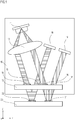
- a first embodiment of the position measuring device according to the invention is described below with reference to FIGS. 1-7 explained.
- the scanning unit 10 and the material measure 20 are connected to objects, not shown, which are arranged to be movable relative to one another at least along the measuring direction indicated by x in the figures.
- the objects may be, for example, relatively movable machine components whose position must be detected relative to each other.
- the position signals generated by the position-measuring device are fed to a higher-level machine control (not shown in the figures) which further processes them in a known manner and uses them eg for positioning the movable machine components.
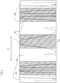
- FIG. 1 shown position measuring device can be generated from the optical scanning of an arranged on the measuring scale 20 and extending in the measuring direction x incremental 21 in the case of relative movement of the scanning unit 10 and measuring scale 20 a plurality of phase-shifted periodic incremental signals.
- the measuring direction x is in FIG. 1 oriented perpendicular to the plane of the drawing.
- the incremental signals generated in this way are used in a known manner for detecting the relative movement of measuring scale 20 and scanning unit 10.
- several reference marks can be provided be, for example, so-called distance-coded reference marks.
- a defined absolute reference for the incremental signals can be established via the reference signal REF. After passing over the reference mark 22 and the subsequently explained generation of a reference signal REF, it is possible to refer the high-resolution incremental signals to the known reference position X REF . Accordingly, as soon as the referencing has taken place, a high-resolution absolute position determination with respect to the two objects can be carried out with the aid of the position-measuring device according to the invention.
- the scanning unit 10 For the optical scanning of the incremental graduation 21 and the reference marking 22 on the measuring standard 20, the scanning unit 10 comprises a light source 11, a collimator optics 12, a scanning plate 13, an incremental signal detector arrangement 19 for detecting the incremental signals and a reference signal detector arrangement 18 for detecting the reference signal REF , On the scanning plate 13, a reference mark scanning structure 14, an incremental graduation scanning structure 16 and optically inoperative window areas 15, 17 are further arranged.
- a reference mark scanning structure 14 On the scanning plate 13, a reference mark scanning structure 14, an incremental graduation scanning structure 16 and optically inoperative window areas 15, 17 are further arranged.
- One of the light source 11, designed as a laser diode or LED emitted beam undergoes collimation in the scanning unit 10 via the collimating optics 12 and is thereby converted into a parallel beam.
- the beam then impinges upon the reference mark sensing structure 14 on top of the scanning plate 13.
- this angle is about 8 °, of course alternative oblique angles are also within the scope of the present invention Invention possible.
- After passing through the reference mark scanning structure 14 passes Beam subsequently onto the material measure 20, here experiences an interaction with the reference mark 22 at the reference position X REF and is reflected back again in the direction of the scanning unit 10. There it passes through an optically ineffective window area 15 in the scanning plate 13 and then encounters the reference signal detector arrangement 18.
- FIG. 1 Starting from the light source 11, via the collimating optics 12, the incremental graduation scanning structure 16, the incremental graduation 21 on the material measure 20 and a further transparent window area 17 in the scanning 13, this bundle of rays arrives at the incremental signal Detector arrangement 19.
- the remainder of FIG EP 1 081 457 A2 referred to the applicant.
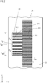
- FIG. 2 A plan view of a region of the material measure 20, which is embodied as an incident-light amplitude grating and in which a reference mark 22 is arranged next to the incremental graduation 21, is shown in FIG FIG. 2 shown.
- the incremental graduation 21 consists of a periodic arrangement of graduation regions 21.1, 21.2 with different reflection properties in the measuring direction x.
- the various division regions 21.1, 21.2 each have a rectangular shape, wherein the rectangular longitudinal axes extend in the arrangement plane along the specified y-direction, ie perpendicular to the measuring direction x. While the division regions 21.1 shown brightly in the figure have a high reflectivity, the dark graduation regions 21.2 of the incremental graduation 21 have only a low reflectivity in the present exemplary embodiment.
- the periodicity of the incremental division 21 is in FIG. 2 denoted by P INC, M , ie the width of a rectangular division region 21.1 or 21.2 is P INC, M / 2, respectively.
- At least one positionally known reference position X REF is in accordance with FIG. 2 along the measuring direction x a reference mark 22 on the measuring scale 20 is arranged, which also consists of an extending in the measuring direction x arrangement of division regions 22.1, 22.2.
- the reference mark 22 has the length I REF, M along the measuring direction x.
- the alternatingly arranged dividing regions 22.1, 22.2 are present in the same way as in the incremental graduation 21 and also of high and low reflective design.
- the arrangement of the graduation regions 22. 1, 22. 2 of the reference mark 22 on the material measure 20 has location-dependent varying graduation periods.
- the term also refers to so-called chirped structures.
- a third grid spatial frequency distribution is mentioned.
- the reference marking 22 comprises two chirped reference marking subfields 22 A , 22 B which are mirror-symmetrically arranged or formed relative to a reference mark symmetry axis S M and have the length I REF, M / 2 along the measuring direction x.
- the reference mark symmetry axis S M is oriented parallel to the direction y, ie perpendicular to the measuring direction x.
- the graduation periods of the divided areas 22.1, 22.2 to the outside always smaller or the corresponding grating spatial frequencies increase.
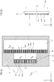
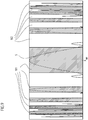
- FIG. 3a A plan view of the scanning 13 of the present embodiment of the position measuring device 13 according to the invention FIG. 3a ; A sectional view through the reference mark sensing structure 14 is shown in FIG FIG. 3b shown.
- the scanning plate 13 here acts as a glass plate in which the various graduation regions 14.1-14.3, 16.1-16.3 of the different scanning structures 14, 16 are formed as absorbing chromium webs, permeable glass regions and deeply etched, phase-shifting glass regions of the respectively provided combined amplitude and phase structures.
- the transparent window area 17 can be seen, which the bundles of rays reflected back from the material measure 20 undergo for generating the incremental signal prior to impinging on the incremental signal detector arrangement 19.
- the incremental pitch scanning structure 16 extending along the measuring direction x is designed as a periodic combined amplitude and phase structure such as that mentioned above EP 1 082 457 A2 is known.
- the amplitude structure of the incremental graduation scanning structure 16 is in this case formed from the periodically arranged, dark and bright, rectangular graduation areas 16.1, 16.2, which are impermeable and permeable to the light incident thereon.
- the amplitude structure of the incremental graduation scanning structure 16 has the periodicity P INC , A1 , which corresponds to the sum of the width of transmissive and impermeable partial regions 16.1, 16.2 along the measuring direction x, as shown in FIG. 3a is illustrated.
- the phase structure of the incremental graduation scanning structure 16 is formed by periodically along the measuring direction x, deep etched division regions 16.3 of the scanning 13, which also are rectangular and in FIG. 3a be shown hatched.
- the division regions 16.3 have a defined phase-shifting effect on the penetrating radiation beams.
- P INC , A2 is in FIG. 3a denotes the periodicity of the phase structure or of the phase-shifting division areas 16.3 in the incremental graduation scanning structure 16.
- FIG. 3a In the y-direction on the right adjacent to the incremental pitch scanning structure 16 is shown in FIG. 3a the transparent window area 17 can be seen in the scanning plate 13, which the bundles of rays reflected back from the material measure 20 pass through for reference signal generation before striking the incremental signal detector arrangement 19.
- the reference mark scanning structure 14 is formed on the scanning plate 13, namely as an arrangement of graduation regions 14.1, 14.2, 14.3 with location-varying graduation periods, ie as a chirped transmission grating.
- the reference mark scanning structure 14 has the limited length I REF, A ; this is in one possible embodiment approximately identical to the length I REF, M of the reference mark 22 on the material measure 20.
- the reference mark scanning structure 14 is also formed as a combined amplitude and phase structure and comprises impermeable division regions 14.1, permeable division regions 14.2 and deeply etched division regions 14.3 in which the transmitted beams undergo a defined phase shift.
- the reference mark sensing structure 14 is as shown FIG. 3a is formed as a chirped structure, ie, the arrangement of the division regions 14.1, 14.2, 14.3 in the reference mark scanning structure 13.2 is selected such that the graduation periods vary depending on location.
- the reference marking scanning structure 14 on the scanning plate 13 in the exemplary embodiment shown comprises two scanning structure subfields arranged mirror-symmetrically to a scanning structure symmetry axis S A 14 A, 14 B.
- the scanning structure symmetry axis S M is oriented parallel to the direction y, ie perpendicular to the measuring direction x.
- the graduation periods of the divided areas 14.1, 14.2, 14.3 outward getting smaller.
- the chirped reference mark scanning structure 14 can also be characterized via a grating spatial frequency distribution. This is referred to below as the first grating spatial frequency distribution and differs from the third grating spatial frequency distribution of the reference mark 22 on the material measure 20. Accordingly, in the frequency domain in the present embodiment of the reference mark scanning structure 14 analog to the reference mark 22, the grating spatial frequencies starting from the sampling structure -Symmetrieachse S A towards the outside ever larger; the graduation periods, however, are in the scanning structure subfields 14 A, 14 B as shown in FIG. 3a visible to the outside smaller and smaller.
- the reference mark scanning structure 14 in the form of the described combined amplitude and phase structure is ensured in this embodiment that in the beam path for scanning the reference mark 22 from the interaction of the emitted light source from the beam with the reference mark sensing structure 14 predominantly +/- 1. Diffraction orders result in transmission behind the scanning 13 and contribute to the generation of the reference signal REF. The formation of other diffraction orders at the reference mark sensing structure 14 is determined by the selected one Design of the reference mark scanning structure 14, however, largely suppressed.
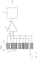
- FIG. 4 A schematic representation of the reference signal detector arrangement 18 of the position measuring device according to the invention including downstream signal processing components is shown in FIG FIG. 4 shown.
- the reference signal detector arrangement 18 consists of a plurality of rectangular detector elements 18.1, 18.2, which are arranged periodically along the measuring direction x.
- the corresponding detector periodicity is also referred to below as the quantity d v ; on the importance of this size will be discussed in the further course of the description.
- each second detector element 18.1, 18.2 of the reference signal detector arrangement 18 is electrically interconnected, so that a first group with interconnected detector elements 18.1 and a second group of interconnected detector elements 18.2 is present.
- a first sub-signal which is hereinafter referred to as the reference clock signal REF T ;
- the second set of interconnected detector elements 18.2 results in a second partial signal, which is referred to below as the reference push-pull signal REF GT .
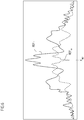
- the course of the signals REF T , REF GT in the region of the reference position X REF is in FIG. 6 shown.
- the reference clock signal REF T and the reference push-pull signal REF GT become as if FIG. 4 can be seen supplied to a subtraction element 30, at the output then the signal REF 'results.
- This signal REF ' is finally subjected via the correction unit 40 to a signal correction, in particular an offset correction.
- the reference signal REF for further processing, for example by a - not shown - control unit ready, whose course in the range of the reference position X REF in FIG. 7 is shown.
- the reference mark scanning structure 14 Due to the above-described design of the reference mark scanning structure 14, a superimposition of diffracted partial beams of +/- 1st order results after this element in the beam path. A self-image of the reference mark scanning structure 14 arranged on the scanning plate 13 is thereby produced over a relatively large distance range between the scale 20 and the scanning unit 10.
- the self-image of the reference mark scanning structure 14 resulting in the scale of measurement thus again represents a chirped structure, but due to the intended design of the reference mark sensing structure 14, the self-image has a second grating spatial frequency distribution which differs from the first grating spatial frequency distribution of the reference mark Sampling structure 14 is different.
- a frequency doubled self-image of the reference mark sensing structure 14 is present in the scale plane, ie, the pitch regions of the self-image have pitch periods that are one-half the pitch periods in the corresponding regions of the reference mark sensing structure 14.
- the thus generated Self-image also has a longitudinal extent which corresponds approximately to the length I REF, A of the reference mark scanning structure 14.
- the second grating spatial frequency distribution of the self-image in the material scale is shifted relative to the third grating spatial frequency of the reference mark 22 by a specific difference frequency f v is.
- a specific difference frequency f v is.
- also possible to set the required difference frequency f v by the appropriate design of the reference mark 22 on the scale 20th From the optical interaction of the generated self-image of the reference mark scanning structure 14 with the reference mark 22 results in the detection plane of the reference signal detector array 18, a stripe pattern with a periodic spatial frequency component when the measuring scale 20 is at the reference position X REF ; the periodic spatial frequency component corresponds to the difference frequency f v .
- the detector spatial frequency of the reference signal detector arrangement 18 thus corresponds to the difference frequency f v between the second and third grating spatial frequency distribution.
- the detector elements 18.1 of the first group of detector elements of the reference signal detector arrangement 18 each detect signal maxima in the generated fringe pattern in the detection plane.
- the signal minima in the fringe pattern in the detection plane are detected via the detector elements 18.2 of the second group.
- FIG. 5 is exactly this case illustrated schematically; here, the resulting stripe pattern S at the reference position X REF and the signal maxima and the signal minima associated detector elements 18.1, 18.2 of the reference signal detector assembly 18.
- the resulting at the reference position X REF from the interconnected detector elements 18.1 of the first group reference clock signal REF T and the reference push-pull signal REF GT resulting from the interconnected detector elements 18.2 of the second group is in FIG. 6 shown; in FIG. 7 is the resulting from the differential connection of the reference clock signal REF T with the reference push-pull signal REF GT and offset corrected reference signal REF illustrated.
- high-reflecting and low-reflective division regions on the material measure 20 can also be correspondingly exchanged.
- a transmission value T (x) 0 is achieved in the reference mark sensing structure 14 by the application of an absorbing layer in a corresponding division region.
- FIGS. 8 and 9 show analogous representations to the FIGS. 4 and 5 of the first embodiment, namely a plan view of a portion of the detector array and a representation of the resulting fringe pattern in the detection plane in conjunction with some detector elements.
- FIGS. 4 and 5 of the first embodiment show analogous representations to the FIGS. 4 and 5 of the first embodiment, namely a plan view of a portion of the detector array and a representation of the resulting fringe pattern in the detection plane in conjunction with some detector elements.
- the reference signal detector arrangement 180 comprises a multiplicity of rectangular detector elements 181, 182 which are arranged aperiodically in the measuring direction x.
- the local detector spatial frequency of the reference signal detector arrangement 180 corresponds to the local difference frequency between the second and third grating spatial frequency distribution on the side of the self-image and the reference mark on the material measure.
- the reference mark scanning structure on the scanning plate is again particularly suitable.
- FIG. 5 analog representation is for the second embodiment in FIG. 9 shown.
- the resulting fringe pattern S at the reference position X REF as well as the detector elements 181, 182 of the reference signal detector arrangement 180 assigned to the signal maxima and the signal minima can be seen from the interconnected detector elements 181 of the first group, the reference clock signal REF T results from the interconnected ones Detector elements 182 of the second group results in the reference push-pull signal REF GT , which after the Differenzversciens and the signal correction according to FIG. 8 provide the reference signal REF.
- an aperiodic arrangement of detector elements can also be provided in the position measuring device according to the invention if a corresponding fringe pattern is generated in the detection plane. Another advantage of such a variant results in the possibility of using signal waveforms which have a particularly high useful signal component.
- the present invention can be realized.
- the material measure would then be formed as transmitted-light amplitude gratings with division regions of different permeability.
- the illumination of the scanning could be carried out vertically here, in contrast to the above-described variant, resulting in an improved insensitivity to variations in the scanning distance would result.
- phase structures consisting of periodically arranged dividing regions having different phase-shifting effects.
- the graduation areas also have a transverse structuring and provide predominantly +/- 1. diffraction orders in transmission.
Description
Die vorliegende Erfindung betrifft eine Positionsmesseinrichtung gemäß dem Oberbegriff von Anspruch 1.The present invention relates to a position measuring device according to the preamble of claim 1.
Aus der
In
Die aus der
Der vorliegenden Erfindung liegt die Aufgabe zugrunde, eine Positionsmesseinrichtung anzugeben, welche unter Verwendung einfach herstellbarer Maßverkörperungen die zuverlässige Erzeugung eines oder mehrerer Referenzsignale ermöglicht.The present invention has for its object to provide a position measuring device, which allows the use of easily manufacturable material measure the reliable generation of one or more reference signals.
Diese Aufgabe wird erfindungsgemäß durch eine Positionsmesseinrichtung mit den Merkmalen des Anspruchs 1 gelöst.This object is achieved by a position measuring device with the features of claim 1.
Vorteilhafte Ausführungen der erfindungsgemäßen Positionsmesseinrichtung ergeben sich aus den Maßnahmen, die in den abhängigen Ansprüchen aufgeführt sind.Advantageous embodiments of the position-measuring device according to the invention will become apparent from the measures listed in the dependent claims.
Die erfindungsgemäße Positionsmesseinrichtung dient zur Erfassung der Position von zwei relativ zueinander in mindestens einer Messrichtung beweglichen Objekten. Sie umfasst eine sich in Messrichtung erstreckende Maßverkörperung, die mit einem der beiden Objekte verbunden ist und mindestens eine Referenzmarkierung an einer Referenzposition aufweist, wobei die Referenzmarkierung aus einer sich in Messrichtung erstreckenden Anordnung von Teilungsbereichen mit ortsabhängig variierenden Teilungsperioden besteht. Ferner umfasst sie eine Abtasteinheit, die mit dem anderen der beiden Objekte verbunden ist und eine Lichtquelle, eine Abtastplatte und eine Referenzsignal-Detektoranordnung aufweist, um mindestens ein Referenzsignal an der Referenzposition zu erzeugen, wobei die Abtastplatte eine Referenzmarkierungs-Abtaststruktur besitzt, die aus einer sich in Messrichtung erstreckenden Anordnung von Teilungsbereichen mit ortsabhängig variierenden Teilungsperioden besteht. Die Anordnung der Teilungsbereiche in der Referenzmarkierung auf der Maßverkörperung und in der Referenzmarkierungs-Abtaststruktur der Abtastplatte ist dergestalt gewählt, dass die Gitter-Ortsfrequenzverteilungen in der Referenzmarkierungs-Abtaststruktur auf der Abtastplatte und in der Referenzmarkierung auf der Maßverkörperung unterschiedlich sind. Des Weiteren ist vorgesehen, dass die Referenzmarkierungs-Abtaststruktur eine erste Gitter-Ortsfrequenzverteilung aufweist und derart ausgebildet ist, dass aus der Wechselwirkung der von der Lichtquelle emittierten Strahlenbündel mit der Referenzmarkierungs-Abtaststruktur vorwiegend +/- 1. Beugungsordnungen resultieren, die überlagert auf der Maßverkörperung ein Selbstabbild der Referenzmarkierungs-Abtaststruktur mit einer zweiten Gitter-Ortsfrequenzverteilung erzeugen.The position-measuring device according to the invention serves to detect the position of two objects which are movable relative to one another in at least one measuring direction. It comprises a measuring standard extending in the measuring direction, which is connected to one of the two objects and has at least one reference mark at a reference position, wherein the reference mark consists of an arrangement of graduation ranges extending in the measuring direction with graduation periods varying with location. It further comprises a scanning unit connected to the other of the two objects and having a light source, a scanning plate and a reference signal detector arrangement for generating at least one reference signal at the reference position, the scanning plate having a reference mark sensing structure consisting of a reference mark extending in the direction of measurement arrangement of division areas with location-dependent varying graduation periods. The arrangement of the division areas in the reference mark on the measuring scale and in the reference mark scanning structure of the scanning plate is selected such that the grid spatial frequency distributions in the reference mark scanning structure on the scanning plate and in the reference mark on the measuring scale are different. Furthermore, it is provided that the reference marking scanning structure has a first grating spatial frequency distribution and is designed in such a way that the interaction of the radiation beams emitted by the light source with the reference marking scanning structure results in predominantly +/- 1 diffraction orders superimposed on the material measure generate a self-image of the reference mark sensing structure with a second grid spatial frequency distribution.
Dabei kann die Referenzmarkierungs-Abtaststruktur als kombinierte Amplituden- und Phasenstruktur ausgebildet sein, die durchlässige, undurchlässige sowie definiert phasenschiebende Teilungsbereiche aufweist.In this case, the reference mark scanning structure may be formed as a combined amplitude and phase structure having transmissive, impermeable and defined phase-shifting division regions.
Alternativ hierzu kann die Referenzmarkierungs-Abtaststruktur als Phasenstruktur ausgebildet sein, die transversal strukturierte Teilungsbereiche aufweist. Außerdem weist die auf der Maßverkörperung angeordnete Referenzmarkierung eine dritte Gitter-Ortsfrequenzverteilung auf. Zudem ist die Referenzmarkierungs-Abtaststruktur und/oder die auf der Maßverkörperung angeordnete Referenzmarkierung derart ausgebildet, dass die zweite und dritte Gitter-Ortsfrequenzverteilung im Frequenzraum um eine bestimmte Differenzfrequenz gegeneinander verschoben sind, so dass aus der optischen Wechselwirkung des Selbstabbilds der Referenzmarkierungs-Abtaststruktur mit der Referenzmarkierung in der Detektionsebene der Referenzsignal-Detektoranordnung ein Streifenmuster mit einer periodischen Ortsfrequenzkomponente resultiert, wenn sich die Maßverkörperung an der Referenzposition befindet, wobei die periodische Ortsfrequenzkomponente der Differenzfrequenz entspricht.Alternatively, the reference mark scanning structure may be formed as a phase structure having transversely structured division regions. In addition, the reference mark arranged on the material measure has a third grid spatial frequency distribution. In addition, the reference mark scanning structure and / or the reference mark arranged on the measuring graduation is designed such that the second and third grating spatial frequency distribution are shifted in the frequency space by a certain difference frequency to each other, so that from the optical interaction of the self-image of the reference mark scanning structure with the reference mark in the detection plane of the reference signal detector arrangement, a fringe pattern with a periodic spatial frequency component results when the material measure is at the reference position, the periodic spatial frequency component corresponding to the difference frequency.
Vorzugsweise ist die Referenzmarkierungs-Abtaststruktur derart ausgebildet, dass auf der Maßverkörperung ein ortsfrequenzverdoppeltes Selbstabbild der Referenzmarkierungs-Abtaststruktur resultiert.The reference marking scanning structure is preferably designed in such a way that a locally frequency-doubled self-image of the reference marking scanning structure results on the material measure.
In einer möglichen Ausführungsform ist vorgesehen, dass
- die Referenzmarkierung zwei zu einer Referenzmarkierungs-Symmetrieachse spiegelsymmetrisch ausgebildete Referenzmarkierungs-Teilfelder umfasst und
- die Referenzmarkierungs-Abtaststruktur zwei zu einer Abtaststruktur-Symmetrieachse spiegelsymmetrisch ausgebildete Abtaststruktur-Teilfelder umfasst.
- the reference marking comprises two reference marking subfields which are mirror-symmetrical to a reference marking axis of symmetry and
- the reference mark scanning structure comprises two scanning structure subfields formed mirror-symmetrically to a scanning structure axis of symmetry.
Desweiteren kann die Referenzsignal-Detektoranordnung eine Vielzahl von rechteckförmigen Detektorelementen umfassen, die in Messrichtung periodisch angeordnet sind, wobei die Detektor-Ortsfrequenz der Referenzsignal-Detektoranordnung der Differenzfrequenz zwischen der zweiten und dritten Gitter-Ortsfrequenzverteilung entspricht.Furthermore, the reference signal detector arrangement may comprise a multiplicity of rectangular detector elements which are arranged periodically in the measuring direction, the detector spatial frequency of the reference signal detector arrangement corresponding to the difference frequency between the second and third grid spatial frequency distributions.
Alternativ kann die Referenzsignal-Detektoranordnung auch eine Vielzahl von rechteckförmigen Detektorelementen umfassen, die in Messrichtung aperiodisch angeordnet sind, wobei die lokale Detektor-Ortsfrequenz der Referenzsignal-Detektoranordnung der lokalen Differenzfrequenz zwischen der zweiten und dritten Gitter-Ortsfrequenzverteilung entspricht.Alternatively, the reference signal detector arrangement may also comprise a multiplicity of rectangular detector elements arranged aperiodically in the measuring direction, the local detector spatial frequency of the reference signal detector arrangement corresponding to the local difference frequency between the second and third grid spatial frequency distributions.
Vorzugsweise ist vorgesehen, dass jedes zweite Detektorelement der Referenzsignal- Detektoranordnung miteinander elektrisch verschaltet ist, wodurch eine erste Gruppe und eine zweite Gruppe von jeweils miteinander verschalteten Detektorelementen resultiert und über die erste Gruppe ein Referenz-Taktsignal und über die zweite Gruppe ein Referenz-Gegentaktsignal erzeugbar ist.It is preferably provided that every second detector element of the reference signal detector arrangement is electrically connected to one another, resulting in a first group and a second group of detector elements interconnected with each other and via the first group Reference clock signal and the second group, a reference push-pull signal can be generated.
Dabei kann die Referenzsignal-Detektoranordnung derart ausgebildet sein, dass an der Referenzposition die Detektorelemente der ersten Gruppe ein Signalmaximum eines in der Detektionsebene der Referenzsignal-Detektoranordnung resultierenden Streifenmusters erfassen und die Detektorelemente der zweiten Gruppe ein Signalminimum des in der Detektionsebene der Referenzsignal- Detektoranordnung resultierenden Streifenmusters erfassen.In this case, the reference signal detector arrangement can be configured such that at the reference position the detector elements of the first group detect a signal maximum of a strip pattern resulting in the detection plane of the reference signal detector arrangement and the detector elements of the second group detect a signal minimum of the strip pattern resulting in the detection plane of the reference signal detector arrangement to capture.
Es ist möglich, dass das Referenz-Taktsignal und das Referenz-Gegentaktsignal miteinander in Differenz verschaltet sind und an der Referenzposition aus dem verschalteten Referenz-Taktsignal und dem Referenz-Gegentaktsignal das Referenzsignal resultiert.It is possible that the reference clock signal and the reference push-pull signal are interconnected with each other in difference and results in the reference position of the interconnected reference clock signal and the reference push-pull signal, the reference signal.
Mit Vorteil ist die Maßverkörperung als Auflicht-Amplitudengitter ausgebildet ist und die Referenzmarkierung umfasst alternierend angeordnete Teilungsbereiche unterschiedlicher Reflektivität.Advantageously, the material measure is configured as an incident light amplitude grating, and the reference marking comprises alternately arranged division regions of different reflectivity.
Schließlich kann vorgesehen werden, dass auf der Maßverkörperung desweiteren eine sich in Messrichtung erstreckende Inkrementalteilung angeordnet ist und die Abtasteinheit Abtastmittel umfasst, um aus der Abtastung der Inkrementalteilung ein oder mehrere positionsabhängige Inkrementalsignale zu erzeugen.Finally, it can be provided that an incremental graduation extending in the measuring direction is arranged on the material measure and the scanning unit comprises scanning means for generating one or more position-dependent incremental signals from the scanning of the incremental graduation.
Aufgrund der erfindungsgemäßen Ausbildung der Positionsmesseinrichtung können nunmehr auch Maßverkörperungen zur Erzeugung eines Referenzsignals abgetastet werden, die kein aufwändiges Herstellverfahren erfordern. Insbesondere ist hierbei der Einsatz von Amplitudengittern als Maßverkörperung möglich, die sowohl im Auflicht als auch im Durchlicht zur Erzeugung von Positionssignalen abtastbar sind.Due to the design of the position measuring device according to the invention, it is now also possible to scan material measures for generating a reference signal which do not require a complex manufacturing process. In particular, in this case the use of amplitude gratings as a material measure is possible, which can be scanned both in reflected light and in transmitted light for the generation of position signals.
Als weiterer Vorteil der erfindungsgemäßen Lösung resultiert eine große Unempfindlichkeit der Signalerzeugung gegenüber Schwankungen des Abtastabstands, also des Abstands zwischen Maßverkörperung und Abtasteinheit. Es ergeben sich damit relativ große Montagetoleranzen für die erfindungsgemäße Positionsmesseinrichtung, was deren Anbau in der jeweiligen Anwendung deutlich erleichtert. Ferner kann damit die erfindungsgemäße Positionsmesseinrichtung auch in Anwendungen eingesetzt werden, die ansonsten im Fall geringerer Montagetoleranzen nicht zugänglich wären.Another advantage of the solution according to the invention results in a great insensitivity of the signal generation to fluctuations in the scanning distance, ie the distance between the measuring scale and the scanning unit. This results in relatively large mounting tolerances for the position measuring device according to the invention, which makes their cultivation significantly easier in the respective application. Furthermore, the position-measuring device according to the invention can thus also be used in applications which would otherwise not be accessible in the case of lower assembly tolerances.
Weitere Einzelheiten und Vorteile der vorliegenden Erfindung seien anhand der nachfolgenden Beschreibung von Ausführungsbeispielen der erfindungsgemäßen Vorrichtung in Verbindung mit den Figuren erläutert.Further details and advantages of the present invention will be explained with reference to the following description of embodiments of the device according to the invention in conjunction with the figures.
Es zeigt
- Figur 1
- eine schematisierte Darstellung der Abtaststrahlengänge in einem ersten Ausführungsbeispiel der erfindungsgemäßen Positionsmesseinrichtung;
- Figur 2
- eine Draufsicht auf einen Teilbereich der Maßverkörperung der Positionsmesseinrichtung aus
Figur 1 , in dem neben einer Inkrementalteilung eine Referenzmarkierung angeordnet ist; - Figur 3a
- eine Draufsicht auf die Abtastplatte der Positionsmesseinrichtung aus
Figur 1 ; - Figur 3b
- eine Schnittansicht der Abtastplatte aus
Figur 3a im Bereich der Referenzmarkierungs-Abtaststruktur; - Figur 4
- eine Draufsicht auf einen Teilbereich der Detektoranordnung der Positionsmesseinrichtung aus
Figur 1 sowie verschiedene nachgeordnete Komponenten zur Erzeugung des Referenzsignals; - Figur 5
- eine Darstellung des resultierenden Streifenmusters in der Detektionsebene der Positionsmesseinrichtung aus
Figur 1 im Fall eines resultierenden maximalen Referenzsignals sowie einen Teil der Detektorelemente der Detektoranordnung; - Figur 6
- eine Darstellung des Verlaufs des Referenz-Taktsignals und des Referenz-Gegentaktsignals in Abhängigkeit von der Position der Maßverkörperung in der Positionsmesseinrichtung aus
Figur 1 ; - Figur 7
- eine Darstellung des aus der Differenz-Verschaltung des Referenz-Taktsignals und des Referenz-Gegentaktsignals resultierenden Referenzsignals der Positionsmesseinrichtung aus
Figur 1 ; - Figur 8
- eine Draufsicht auf einen Teilbereich der Detektoranordnung eines zweiten Ausführungsbeispiels der erfindungsgemäßen Positionsmesseinrichtung sowie verschiedene nachgeordnete Komponenten zur Erzeugung des Referenzsignals;
- Figur 9
- eine Darstellung des resultierenden Streifenmusters in der Detektionsebene des zweiten Ausführungsbeispiels der erfindungsgemäßen Positionsmesseinrichtung im Fall eines resultierenden maximalen Referenzsignals.
- FIG. 1
- a schematic representation of the scanning beam paths in a first embodiment of the position measuring device according to the invention;
- FIG. 2
- a plan view of a portion of the measuring graduation of the position measuring device
FIG. 1 in which a reference mark is arranged in addition to an incremental graduation; - FIG. 3a
- a plan view of the scanning of the position measuring device
FIG. 1 ; - FIG. 3b
- a sectional view of the scanning from
FIG. 3a in the area of the reference mark scanning structure; - FIG. 4
- a plan view of a portion of the detector assembly of the position measuring device
FIG. 1 and various downstream components for generating the reference signal; - FIG. 5
- a representation of the resulting fringe pattern in the detection plane of the position measuring device
FIG. 1 in the case of a resulting maximum reference signal and a part of the detector elements of the detector array; - FIG. 6
- a representation of the course of the reference clock signal and the reference push-pull signal as a function of the position of the material measure in the position-measuring device
FIG. 1 ; - FIG. 7
- a representation of the reference signal of the position measuring device resulting from the differential connection of the reference clock signal and the reference push-pull signal
FIG. 1 ; - FIG. 8
- a plan view of a portion of the detector arrangement of a second embodiment of the position measuring device according to the invention and various downstream components for generating the reference signal;
- FIG. 9
- a representation of the resulting fringe pattern in the detection plane of the second embodiment of the position measuring device according to the invention in the case of a resulting maximum reference signal.
Ein erstes Ausführungsbeispiel der erfindungsgemäßen Positionsmesseinrichtung wird nachfolgend anhand der
Wie aus der schematisierten Darstellung der Abtaststrahlengänge in
Über die in
Zur optischen Abtastung der Inkrementalteilung 21 und der Referenzmarkierung 22 auf der Maßverkörperung 20 umfasst die Abtasteinheit 10 eine Lichtquelle 11, eine Kollimatoroptik 12, eine Abtastplatte 13, eine Inkrementalsignal-Detektoranordnung 19 zur Erfassung der Inkrementalsignale sowie eine Referenzsignal-Detektoranordnung 18 zur Erfassung des Referenzsignals REF. Auf der Abtastplatte 13 sind ferner eine Referenzmarkierungs-Abtaststruktur 14, eine Inkrementalteilungs-Abtaststruktur 16 sowie optisch unwirksame Fensterbereiche 15, 17 angeordnet. Hinsichtlich der genauen Ausbildung der verschiedenen Komponenten zur Signalerzeugung sei auf die nachfolgende Beschreibung des Abtaststrahlengangs zur erfindungsgemäßen Erzeugung des Referenzsignals REF verwiesen.For the optical scanning of the
Ein von der Lichtquelle 11, ausgebildet als Laserdiode oder LED, emittiertes Strahlenbündel (in
Ähnlich hierzu verläuft auch der Abtaststrahlengang zur Erzeugung der positionsabhängigen Inkrementalsignale mittels geeigneter Abtastmittel. In
Eine Draufsicht auf einen Bereich der Maßverkörperung 20, die als Auflicht-Amplitudengitter ausgebildet ist und in dem neben der Inkrementalteilung 21 eine Referenzmarkierung 22 angeordnet ist, ist in
An mindestens einer lagemäßig bekannten Referenzposition XREF ist gemäß
Im Unterschied zur periodisch ausgebildeten Inkrementalteilung 21 weist die Anordnung der Teilungsbereiche 22.1, 22.2 der Referenzmarkierung 22 auf der Maßverkörperung 20 ortsabhängig variierende Teilungsperioden auf, nachfolgend sei diesbezüglich auch die Rede von sog. gechirpten Strukturen. Alternativ zur Betrachtung der die Referenzmarkierung 22 charakterisierenden ortabhängig variierenden Teilungsperioden kann auch von einer Gitter-Ortsfrequenzverteilung der Referenzmarkierung 22 gesprochen werden. Im Zusammenhang mit der Referenzmarkierung 22 auf der Maßverkörperung 20 sei in der nachfolgenden Beschreibung von einer dritten Gitter-Ortsfrequenzverteilung die Rede.In contrast to the periodically formed
Im konkreten Ausführungsbeispiel der
Grundsätzlich wäre auch ein umgekehrter Verlauf der Gitter-Ortsfrequenzen in der Referenzmarkierung im Rahmen der vorliegenden Erfindung möglich. In diesem Fall würden also die Gitter-Ortsfrequenzen nach außen hin immer kleiner bzw. die Teilungsperioden immer größer.In principle, a reverse course of the grating spatial frequencies in the reference mark would also be possible in the context of the present invention. In this case, therefore, the grating spatial frequencies would become smaller and the graduation periods ever larger.
Eine Draufsicht auf die Abtastplatte 13 des vorliegenden Ausführungsbeispiels der erfindungsgemäßen Positionsmesseinrichtung 13 zeigt
Im rechten Teil der in
In y-Richtung rechts benachbart zur Inkrementalteilungs-Abtaststruktur 16 ist gemäß
Unterschiedlich zur Inkrementalteilungs-Abtaststruktur 17 ist auf der Abtastplatte 13 die Referenzmarkierungs-Abtaststruktur 14 ausgebildet, nämlich als Anordnung von Teilungsbereichen 14.1, 14.2, 14.3 mit ortsabhängig variierenden Teilungsperioden, d.h. als gechirptes Transmissionsgitter. Entlang der Messrichtung x besitzt die Referenzmarkierungs-Abtaststruktur 14 die begrenzte Länge IREF,A; diese ist in einem möglichen Ausführungsbeispiel in etwa identisch zur Länge IREF,M der Referenzmarkierung 22 auf der Maßverkörperung 20. Auch die Referenzmarkierungs-Abtaststruktur 14 ist als kombinierte Amplituden- und Phasenstruktur ausgebildet und umfasst undurchlässige Teilungsbereiche 14.1, durchlässige Teilungsbereiche 14.2 sowie tiefgeätzte Teilungsbereiche 14.3, in denen die transmittierten Strahlenbündel eine definierte Phasenverschiebung erfahren.In contrast to the incremental
Die Referenzmarkierungs-Abtaststruktur 14 ist wie aus
Im Fall der oben erwähnten alternativen Ausbildung der Referenzmarke mit nach außen hin größer werdenden Teilungsperioden müsste natürlich auch die Referenzmarkierungs-Abtaststruktur entsprechend angepasst ausgebildet werden. Diese würde dann ebenfalls nach außen hin größer werdende Teilungsperioden besitzen.In the case of the above-mentioned alternative design of the reference mark with outwardly increasing graduation periods, of course, the reference mark scanning structure would have to be adapted accordingly. This would then also have outwardly increasing graduation periods.
Wie schon im Fall der Referenzmarkierung 22 auf der Maßverkörperung 20 kann auch die gechirpte Referenzmarkierungs-Abtaststruktur 14 über eine Gitter-Ortsfrequenzverteilung charakterisiert werden. Diese sei nachfolgend als erste Gitter-Ortsfrequenzverteilung bezeichnet und unterscheidet sich von der dritten Gitter-Ortsfrequenzverteilung der Referenzmarkierung 22 auf der Maßverkörperung 20. Im Frequenzraum werden demnach im vorliegenden Ausführungsbeispiel der Referenzmarkierungs-Abtaststruktur 14 analog zur Referenzmarkierung 22 die Gitter-Ortsfrequenzen ausgehend von der Abtaststruktur-Symmetrieachse SA nach außen hin immer größer; die Teilungsperioden hingegen werden in den Abtaststruktur-Teilfeldern 14A, 14B wie aus
Über die Ausbildung der Referenzmarkierungs-Abtaststruktur 14 in Form der erläuterten kombinierten Amplituden- und Phasenstruktur ist in diesem Ausführungsbeispiel gewährleistet, dass im Strahlengang zur Abtastung der Referenzmarkierung 22 aus der Wechselwirkung der von der Lichtquelle emittierten Strahlenbündel mit der Referenzmarkierungs-Abtaststruktur 14 vorwiegend +/- 1. Beugungsordnungen in Transmission hinter der Abtastplatte 13 resultieren und zur Erzeugung des Referenzsignals REF beitragen. Die Entstehung anderer Beugungsordnungen an der Referenzmarkierungs-Abtaststruktur 14 wird durch die gewählte Ausgestaltung der Referenzmarkierungs-Abtaststruktur 14 dagegen weitgehend unterdrückt.About the formation of the reference
Eine schematisierte Darstellung der Referenzsignal-Detektoranordnung 18 der erfindungsgemäßen Positionsmesseinrichtung inklusive nachgeordneter Signalverarbeitungskomponenten ist in
Wie in
Das Referenz-Taktsignal REFT und das Referenz-Gegentaktsignal REFGT werden wie aus
Im folgenden wird nunmehr die Erzeugung des Referenzsignals REF mit Hilfe der vorhergehend beschriebenen erfindungsgemäßen Positionsmesseinrichtung im Detail erläutert.In the following, the generation of the reference signal REF will now be explained in detail with the aid of the above-described position-measuring device according to the invention.
Aufgrund der oben beschriebenen Ausbildung der Referenzmarkierungs-Abtaststruktur 14 resultiert nach diesem Element im Strahlengang eine Überlagerung von gebeugten Teilstrahlenbündeln +/- 1. Ordnung. Über einen relativ großen Abstandsbereich zwischen Maßverkörperung 20 und Abtasteinheit 10 wird dadurch ein Selbstabbild der auf der Abtastplatte 13 angeordneten Referenzmarkierungs-Abtaststruktur 14 erzeugt. Das in der Maßverkörperungsebene resultierende Selbstabbild der Referenzmarkierungs-Abtaststruktur 14 stellt somit ebenfalls wieder eine gechirpte Struktur dar, wobei das Selbstabbild aufgrund der vorgesehenen Ausbildung der Referenzmarkierungs-Abtaststruktur 14 jedoch eine zweite Gitter-Ortsfrequenzverteilung aufweist, die sich von der ersten Gitter-Ortsfrequenzverteilung der Referenzmarkierungs-Abtaststruktur 14 unterscheidet. In einem bevorzugten Ausführungsbeispiel liegt ein ortsfrequenzverdoppeltes Selbstabbild der Referenzmarkierungs-Abtaststruktur 14 in der Maßverkörperungsebene vor, d.h. die Teilungsbereiche des Selbstabbilds besitzen Teilungsperioden, die halb so groß sind wie die Teilungsperioden in den entsprechenden bzw. korrespondierenden Bereichen der Referenzmarkierungs-Abtaststruktur 14. Das derart erzeugte Selbstabbild besitzt ferner eine Längsausdehnung, die etwa der Länge IREF, A der Referenzmarkierungs-Abtaststruktur 14 entspricht.Due to the above-described design of the reference
Über eine geeignete Ausbildung der Referenzmarkierungs-Abtaststruktur 14 wird im vorliegenden Ausführungsbeispiel ferner sichergestellt, dass die zweite Gitter-Ortsfrequenzverteilung des Selbstabbilds in der Maßverkörperungsebene gegenüber der dritten Gitter-Ortsfrequenz der Referenzmarkierung 22 um eine bestimmte Differenzfrequenz fv verschoben ist. Alternativ hierzu wäre es grds. auch möglich, die erforderliche Differenzfrequenz fv durch die geeignete Ausbildung der Referenzmarkierung 22 auf der Maßverkörperung 20 einzustellen. Aus der optischen Wechselwirkung des erzeugten Selbstabbilds der Referenzmarkierungs-Abtaststruktur 14 mit der Referenzmarkierung 22 resultiert in der Detektionsebene der Referenzsignal-Detektoranordnung 18 ein Streifenmuster mit einer periodischen Ortsfrequenz-Komponente, wenn sich die Maßverkörperung 20 an der Referenzposition XREF befindet; die periodische Ortsfrequenz-Komponente entspricht hierbei der Differenzfrequenz fv. Das erzeugte Streifenmuster wird dann mit Hilfe der Referenzsignal-Detektoranordnung 18 mit der gewählten Detektor-Ortsfrequenz fv bzw. der Detektor-Periodizität dv = 1/fv erfasst. Die Detektor-Ortsfrequenz der Referenzsignal-Detektoranordnung 18 entspricht damit der Differenzfrequenz fv zwischen der zweiten und dritten Gitter-Ortsfrequenzverteilung.By means of a suitable design of the reference
Befindet sich die Abtasteinheit 10 unmittelbar über der Referenzmarkierung 22, so erfassen die Detektorelemente 18.1 der ersten Gruppe von Detektorelementen der Referenzsignal-Detektoranordnung 18 jeweils Signalmaxima im erzeugten Streifenmuster in der Detektionsebene. Über die Detektorelemente 18.2 der zweiten Gruppe werden die Signalminima im Streifenmuster in der Detektionsebene erfasst. In
Abschließend sei für das erste Ausführungsbeispiel der erfindungsgemäßen Positionsmesseinrichtung erläutert, wie die zur Erzeugung des Referenzsignals beitragenden Komponenten im Abtaststrahlengang mathematisch charakterisierbar sind, um derart die nötigen Strukturen gezielt zu dimensionieren.Finally, for the first exemplary embodiment of the position-measuring device according to the invention, it will be explained how the components contributing to the generation of the reference signal in the scanning beam path can be mathematically characterized so as to specifically dimension the necessary structures.
So kann die ortsabhängige Phasenfunktion pM (x) der Referenzmarkierung 22 auf der Maßverkörperung 20 z.B. durch das nachfolgende Polynom beschrieben werden: ![]()
- pM (x)
- := ortsabhängige Phasenfunktion der Referenzmarkierung auf der Maßverkörperung
- a,b
- := Polynomkoeffizienten
- x
- := Ortskoordinate entlang der Messrichtung
- p M ( x )
- : = location-dependent phase function of the reference mark on the material measure
- from
- : = Polynomial coefficients
- x
- : = Location coordinate along the measuring direction
Aus der Phasenfunktion pM (x) der Referenzmarkierung 22 auf der Maßverkörperung 20 können die Teilungsbereiche der Referenzmarkierung 22 auf der Maßverkörperung 20 mit hoher bzw. niedriger Reflexion wie folgt direkt bestimmt werden: ![]()
- R(x)
- := ortsabhängige Reflektivität der Referenzmarkierung auf Maßverkörperung
- pM (x)
- := ortsabhängige Phasenfunktion der Referenzmarkierung auf der Maßverkörperung
- x
- := Ortskoordinate entlang der Messrichtung
- R (x)
- : = location-dependent reflectivity of the reference marking on the material measure
- p M ( x )
- : = location-dependent phase function of the reference mark on the material measure
- x
- : = Location coordinate along the measuring direction
Grundsätzlich können hierbei hoch-reflektierende und gering-reflektierende Teilungsbereiche auf der Maßverkörperung 20 auch entsprechend vertauscht werden.In principle, high-reflecting and low-reflective division regions on the
Das frequenzverdoppelte Selbstabbild der Referenzmarkierungs-Abtaststruktur 14 muss wie bereits oben erläutert um die Detektor-Ortsfrequenz fv = 1/dv der periodischen Referenzsignal-Detektoranordnung 18 verschoben sein.As already explained above, the frequency-doubled self-image of the reference-
Für die Intensitätsverteilung I(x) in der Maßverkörperungsebene gilt hierbei: ![]()
- I(x)
- := ortsabhängige Intensitätsverteilung in der Maßverkörperungsebene
- pAP(X)
- := ortsabhängige Phasenfunktion der Referenzmarkierungs-Abtaststruktur auf der Abtastplatte
- x
- := Ortskoordinate entlang der Messrichtung
- I (x)
- : = location-dependent intensity distribution in the material scale
- p AP (X)
- : = location-dependent phase function of the reference mark scanning structure on the scanning plate
- x
- : = Location coordinate along the measuring direction
Dabei gilt für die ortabhängige Phasenfunktion der Referenzmarkierungs-Abtaststruktur 14 auf der Abtastplatte 13: ![]()
- pAP(X)
- := ortsabhängige Phasenfunktion der Referenzmarkierungs-Abtaststruktur auf der Abtastplatte
- dv
- := Detektor-Periodizität der Referenzsignal-Detektoranordnung
- a, b
- := Polynomkoeffizienten
- x
- := Ortskoordinate entlang der Messrichtung
- p AP (X)
- : = location-dependent phase function of the reference mark scanning structure on the scanning plate
- d. v
- : = Detector periodicity of the reference signal detector array
- a, b
- : = Polynomial coefficients
- x
- : = Location coordinate along the measuring direction
Die komplexe Transmission T(x) der Referenzmarkierungs-Abtaststruktur 14 kann gemäß nachfolgender Gleichung wieder aus der Phasenfunktion der Referenzmarkierungs-Abtaststruktur 14 der Abtastplatte 13 bestimmt werden. 
- T(x)
- := komplexe Transmission T(x) der Referenzmarkierungs-Abtaststruktur
- pAP(X)
- := ortsabhängige Phasenfunktion der Referenzmarkierungs-Abtaststruktur auf der Abtastplatte
- x
- := Ortskoordinate entlang der Messrichtung
- T (x)
- : = complex transmission T (x) of the reference mark sensing structure
- p AP (X)
- : = location-dependent phase function of the reference mark scanning structure on the scanning plate
- x
- : = Location coordinate along the measuring direction
Ein Transmissionswert T(x) = -1 bedeutet hierbei für einen Teilungsbereich der Referenzmarkierungs-Abtaststruktur 14, dass dieser Teilungsbereich tiefgeätzt ausgebildet ist, so dass darüber eine Phasenverschiebung von 180° gegenüber nicht tiefgeätzten Teilungsbereichen bzgl. der durchlaufenden Strahlenbündel erreicht wird. Ein Transmissionswert T(x) = 0 wird in der Referenzmarkierungs-Abtaststruktur 14 durch das Aufbringen einer absorbierenden Schicht in einem entsprechenden Teilungsbereich erreicht.A transmission value T (x) = -1 for a division region of the reference marking
Ein zweites Ausführungsbeispiel er erfindungsgemäßen Positionsmesseinrichtung sei abschließend anhand der
Als wesentlicher Unterschied zum ersten Ausführungsbeispiel ist hier vorgesehen, dass die Referenzsignal-Detektoranordnung 180 eine Vielzahl rechteckförmiger Detektorelemente 181, 182 umfasst, die in Messrichtung x aperiodisch angeordnet sind. Die lokale Detektor-Ortsfrequenz der Referenzsignal-Detektoranordnung 180 entspricht dabei der lokalen Differenzfrequenz zwischen der zweiten und dritten Gitter-Ortsfrequenzverteilung auf Seiten des Selbstabbilds und der Referenzmarkierung auf der Maßverkörperung. Um dies sicherzustellen, ist insbesondere wieder die Referenzmarkierungs-Abtaststruktur auf der Abtastplatte geeignet auszubilden.As an essential difference from the first exemplary embodiment, it is provided here that the reference
Eine zu
Anstelle einer streng periodischen Anordnung von Detektorelementen kann in der erfindungsgemäßen Positionsmesseinrichtung demzufolge auch eine aperiodische Anordnung von Detektorelementen vorgesehen sein, wenn ein entsprechendes Streifenmuster in der Detektionsebene generiert wird. Als weiterer Vorteil einer derartigen Variante resultiert die Möglichkeit, Signalverlaufsformen zu verwenden, die einen besonders hohen Nutzsignalanteil besitzen.Instead of a strictly periodic arrangement of detector elements, accordingly, an aperiodic arrangement of detector elements can also be provided in the position measuring device according to the invention if a corresponding fringe pattern is generated in the detection plane. Another advantage of such a variant results in the possibility of using signal waveforms which have a particularly high useful signal component.
Neben den konkret beschriebenen Ausführungsbeispielen existieren im Rahmen der vorliegenden Erfindung selbstverständlich noch weitere Ausgestaltungsmöglichkeiten.In addition to the embodiments described concretely, there are of course further design possibilities within the scope of the present invention.
So ist beispielsweise möglich, das erläuterte Prinzip sowohl bei Positionsmesseinrichtungen zur Erfassung von linearen Relativbewegungen als auch zur Erfassung von rotatorischen Relativbewegungen einzusetzen. Im letztgenannten Fall können Radialgitter-Maßverkörperungen ebenso wie bandförmige Maßverkörperungen verwendet werden.For example, it is possible to use the described principle both in position-measuring devices for detecting linear relative movements and for detecting rotational relative movements. In the latter case, radial lattice material measures as well as band-shaped material measures can be used.
Desweiteren kann nicht nur eine Auflicht-Positionsmesseinrichtung gemäß dem erläuterten Ausführungsbeispiel erfindungsgemäß ausgebildet werden, auch in Positionsmesseinrichtungen nach dem Durchlichtprinzip ist die vorliegende Erfindung realisierbar. In diesem Fall wäre die Maßverkörperung dann als Durchlicht-Amplitudengitter mit Teilungsbereichen unterschiedlicher Durchlässigkeit auszubilden. Die Beleuchtung der Abtastplatte könnte hier im Unterschied zur oben erläuterten Variante senkrecht erfolgen, was eine verbesserte Unempfindlichkeit gegenüber Schwankungen des Abtastabstands zur Folge hätte.Furthermore, not only an incident-light position-measuring device according to the illustrated embodiment can be formed according to the invention, also in position-measuring devices according to the transmitted-light principle, the present invention can be realized. In this case, the material measure would then be formed as transmitted-light amplitude gratings with division regions of different permeability. The illumination of the scanning could be carried out vertically here, in contrast to the above-described variant, resulting in an improved insensitivity to variations in the scanning distance would result.
Ferner ist es möglich, anstelle der kombinierten Phasen-Amplituden-Abtaststrukturen auf der Abtastplatte Phasenstrukturen vorzusehen, die aus periodisch angeordneten Teilungsbereichen mit unterschiedlichen phasenschiebenden Wirkungen besteht. Die Teilungsbereiche weisen in diesem Fall ferner noch eine transversale Strukturierung auf und liefern in Transmission vorwiegend +/- 1. Beugungsordnungen.Further, instead of the combined phase-amplitude sampling structures on the scanning plate, it is possible to provide phase structures consisting of periodically arranged dividing regions having different phase-shifting effects. In this case, the graduation areas also have a transverse structuring and provide predominantly +/- 1. diffraction orders in transmission.
Claims (11)
- Position measurement device for capturing the position of two objects which are movable relative to one another in at least one measurement direction (x), having- a measuring standard (20) extending in the measurement direction (x), which measuring standard is connected to one of the two objects and has at least one reference mark (22) at a reference position (xREF), wherein the reference mark (22) consists of an arrangement of graduation regions (22.1, 22.2, 14.1, 14.2, 14.3), extending in the measurement direction (x), having graduation periods that vary in dependence on the location,- a scanning unit (10) that is connected to the other one of the two objects and comprises a light source (11), a scanning plate (13) and a reference-signal detector arrangement (18) to generate at least one reference signal (REF) at the reference position (xREF), via which an absolute reference for any further generated periodic incremental signals is able to be produced and wherein the scanning plate (13) has a reference-mark scanning structure (14) which consists of an arrangement of graduation regions (14.1, 14.2, 14.3), extending in the measurement direction (x), having graduation periods that vary in dependence on the location, and wherein- the arrangement of the graduation regions (22.1, 22.2, 14.1, 14.2, 19.3) in the reference mark (22) on the measuring standard (20) and in the reference-mark scanning structure (14) of the scanning plate (13) is selected such that the grating spatial frequency distributions in the reference-mark scanning structure (14) on the scanning plate (13) and in the reference mark (22) on the measuring standard (20) differ, and wherein- the reference-mark scanning structure (14) has a first grating spatial frequency distribution and is configured such that, from the interaction of the beams emitted by the light source (11) with the reference-mark scanning structure (14), primarily +/-1 diffraction orders are obtained that generate, by being superposed onto the measuring standard (20), a self-image of the reference-mark scanning structure (14) having a second grating spatial frequency distribution, characterized- in that the reference mark (22) arranged on the measuring standard (20) has a third grating spatial frequency distribution, and- in that the reference-mark scanning structure (14) and/or the reference mark (14) arranged on the measuring standard (20) are configured such that the second and third grating spatial frequency distributions in the frequency domain are displaced with respect to one another by a specific difference frequency (fv) such that a stripe pattern having a periodic spatial-frequency component is obtained from the optical interaction of the self-image of the reference-mark scanning structure (14) with the reference mark (22) in the detection plane of the reference-signal detector arrangement (18), if the measuring standard (20) is located at the reference position (xREF), wherein the periodic spatial-frequency component corresponds to the difference frequency (fv).
- Position measurement device according to Claim 1, characterized in that the reference-mark scanning structure (14) is configured in the form of a combined amplitude and phase structure having graduation regions (14.1, 14.2, 14.3) that are transmissive, non-transmissive and phase-shifting in a defined manner.
- Position measurement device according to Claim 1, characterized in that the reference-mark scanning structure (14) is configured such that a spatial-frequency-doubled self-image of the reference-mark scanning structure (14) is obtained on the measuring standard (20).
- Position measurement device according to at least one of the preceding claims, characterized in that- the reference mark (22) comprises two reference-mark graduation fields (22A, 22B) that are configured to be mirror-symmetric with respect to a reference-mark symmetry axis (SM), and- the reference-mark scanning structure (14) comprises two scanning-structure graduation fields (14A, 14B) that are configured to be mirror-symmetric with respect to a scanning-structure symmetry axis (SA).
- Position measurement device according to Claim 1, characterized in that the reference-signal detector arrangement (18) comprises a multiplicity of rectangular detector elements (18.1, 18.2) which are arranged periodically in the measurement direction (x), wherein the detector spatial frequency of the reference-signal detector arrangement (18) corresponds to the difference frequency (fv) between the second and third grating spatial frequency distributions.
- Position measurement device according to Claim 1, characterized in that the reference-signal detector arrangement (18) comprises a multiplicity of rectangular detector elements which are arranged aperiodically in the measurement direction (x), wherein the local detector spatial frequency of the reference-signal detector arrangement corresponds to the local difference frequency between the second and third grating spatial frequency distributions.
- Position measurement device according to Claim 5 or 6, characterized in that every other detector element (18.1, 18.2) of the reference-signal detector arrangement (18) is electrically connected to one another, as a result of which a first group and a second group of respectively interconnected detector elements (18.1, 18.2) are obtained and a reference clock signal (REFT) is able to be generated by the first group and a reference counter-clock signal (REFGT) is able to be generated by the second group.
- Position measurement device according to Claim 7, characterized in that the reference-signal detector arrangement (18) is configured such that at the reference position (xREF), the detector elements (18.1) of the first group capture a signal maximum of a stripe pattern resulting in the detection plane of the reference-signal detector arrangement (18) and the detector elements (18.2) of the second group capture a signal minimum of the stripe pattern resulting in the detection plane of the reference-signal detector arrangement (18).
- Position measurement device according to Claim 7, characterized in that the reference clock signal (REFT) and the reference counter-clock signal (REFGT) are differentially connected to one another and, at the reference position (xREF), the reference signal (REF) is obtained from the connected reference clock signal (REFT) and the reference counter-clock signal (REFGT).
- Position measurement device according to at least one of the preceding claims, characterized in that the measuring standard (20) is configured as a reflected-light amplitude grating and the reference mark (22) comprises graduation regions (22.1, 22.2) of different reflectivity which are arranged in alternation.
- Position measurement device according to at least one of the preceding claims, characterized in that furthermore an incremental graduation (21) extending in the measurement direction (x) is arranged on the measuring standard (20), and the scanning unit (10) comprises scanning means in order to generate one or more position-dependent incremental signals from the scan of the incremental graduation (21).
Applications Claiming Priority (1)
| Application Number | Priority Date | Filing Date | Title |
|---|---|---|---|
| DE102014212268.6A DE102014212268A1 (en) | 2014-06-26 | 2014-06-26 | Position measuring device |
Publications (2)
| Publication Number | Publication Date |
|---|---|
| EP2963391A1 EP2963391A1 (en) | 2016-01-06 |
| EP2963391B1 true EP2963391B1 (en) | 2017-08-09 |
Family
ID=53373327
Family Applications (1)
| Application Number | Title | Priority Date | Filing Date |
|---|---|---|---|
| EP15171191.8A Active EP2963391B1 (en) | 2014-06-26 | 2015-06-09 | Position measuring device |
Country Status (3)
| Country | Link |
|---|---|
| EP (1) | EP2963391B1 (en) |
| JP (1) | JP6293700B2 (en) |
| DE (1) | DE102014212268A1 (en) |
Families Citing this family (3)
| Publication number | Priority date | Publication date | Assignee | Title |
|---|---|---|---|---|
| JP6400036B2 (en) | 2016-03-14 | 2018-10-03 | キヤノン株式会社 | Position detection device, machine tool, and exposure device |
| DE102017201257A1 (en) * | 2017-01-26 | 2018-07-26 | Dr. Johannes Heidenhain Gmbh | Position measuring device |
| JP2021193354A (en) | 2020-06-08 | 2021-12-23 | キヤノン株式会社 | Optical encoder and control device |
Family Cites Families (6)
| Publication number | Priority date | Publication date | Assignee | Title |
|---|---|---|---|---|
| DE59102126D1 (en) | 1991-05-18 | 1994-08-11 | Heidenhain Gmbh Dr Johannes | Interferential position measuring device. |
| DE4212281A1 (en) * | 1991-07-11 | 1993-10-14 | Heidenhain Gmbh Dr Johannes | Position-measuring appts. using spatially modulated gratings - produces different aperiodic waveforms from various functional dependences of local grating period on direction of modulation |
| WO1999055832A2 (en) | 1998-04-29 | 1999-11-04 | Merck & Co., Inc. | Nucleic acid encoding rate agouti related protein |
| DE19941318A1 (en) | 1999-08-31 | 2001-03-15 | Heidenhain Gmbh Dr Johannes | Optical position measuring device |
| DE19956912A1 (en) * | 1999-11-26 | 2001-08-09 | Heidenhain Gmbh Dr Johannes | Angle measuring system and angle measuring method for non-contact angle measurement |
| DE102008044858A1 (en) * | 2008-08-28 | 2010-03-04 | Dr. Johannes Heidenhain Gmbh | Optical position measuring device |
-
2014
- 2014-06-26 DE DE102014212268.6A patent/DE102014212268A1/en not_active Withdrawn
-
2015
- 2015-04-20 JP JP2015085718A patent/JP6293700B2/en active Active
- 2015-06-09 EP EP15171191.8A patent/EP2963391B1/en active Active
Non-Patent Citations (1)
| Title |
|---|
| None * |
Also Published As
| Publication number | Publication date |
|---|---|
| JP6293700B2 (en) | 2018-03-14 |
| JP2016008965A (en) | 2016-01-18 |
| EP2963391A1 (en) | 2016-01-06 |
| DE102014212268A1 (en) | 2016-01-14 |
Similar Documents
| Publication | Publication Date | Title |
|---|---|---|
| EP2318812B1 (en) | Optical position measuring device | |
| EP1691172B1 (en) | Position measuring device | |
| EP2738524B1 (en) | Position measuring device | |
| EP0513427B1 (en) | Interferometric position measuring device | |
| DE102015016780B4 (en) | Encoder | |
| EP1081457B1 (en) | Optical position measuring device | |
| EP1923672B1 (en) | Position measuring device | |
| EP3511680B1 (en) | Position measuring device | |
| EP0735346A2 (en) | Opto-electrical position-measuring device | |
| DE102015218539B4 (en) | Optical position measuring device | |
| DE102016015233B4 (en) | CODING DEVICE | |
| EP3339811B1 (en) | Optical positioning device | |
| EP1271107B1 (en) | Position measuring device | |
| EP2963391B1 (en) | Position measuring device | |
| EP1867960B1 (en) | Optical positioning device | |
| EP1028309B1 (en) | Optical encoder | |
| DE102006019491B4 (en) | Optical encoder | |
| EP1617182A2 (en) | Position measuring device | |
| EP3477264A1 (en) | Optical positioning device | |
| EP0747674A2 (en) | Photo-electric position measuring device | |
| DE102016015225B4 (en) | encoder | |
| EP3355034B1 (en) | Position measuring device | |
| DE4212281C2 (en) | ||
| EP1427985B1 (en) | Position measuring system and method for operating such a position measuring system | |
| EP2735848B1 (en) | Optical positioning device |
Legal Events
| Date | Code | Title | Description |
|---|---|---|---|
| PUAI | Public reference made under article 153(3) epc to a published international application that has entered the european phase |
Free format text: ORIGINAL CODE: 0009012 |
|
| AK | Designated contracting states |
Kind code of ref document: A1 Designated state(s): AL AT BE BG CH CY CZ DE DK EE ES FI FR GB GR HR HU IE IS IT LI LT LU LV MC MK MT NL NO PL PT RO RS SE SI SK SM TR |
|
| AX | Request for extension of the european patent |
Extension state: BA ME |
|
| 17P | Request for examination filed |
Effective date: 20160706 |
|
| RBV | Designated contracting states (corrected) |
Designated state(s): AL AT BE BG CH CY CZ DE DK EE ES FI FR GB GR HR HU IE IS IT LI LT LU LV MC MK MT NL NO PL PT RO RS SE SI SK SM TR |
|
| GRAP | Despatch of communication of intention to grant a patent |
Free format text: ORIGINAL CODE: EPIDOSNIGR1 |
|
| INTG | Intention to grant announced |
Effective date: 20170421 |
|
| GRAS | Grant fee paid |
Free format text: ORIGINAL CODE: EPIDOSNIGR3 |
|
| GRAA | (expected) grant |
Free format text: ORIGINAL CODE: 0009210 |
|
| AK | Designated contracting states |
Kind code of ref document: B1 Designated state(s): AL AT BE BG CH CY CZ DE DK EE ES FI FR GB GR HR HU IE IS IT LI LT LU LV MC MK MT NL NO PL PT RO RS SE SI SK SM TR |
|
| REG | Reference to a national code |
Ref country code: GB Ref legal event code: FG4D Free format text: NOT ENGLISH |
|
| REG | Reference to a national code |
Ref country code: CH Ref legal event code: EP Ref country code: AT Ref legal event code: REF Ref document number: 917331 Country of ref document: AT Kind code of ref document: T Effective date: 20170815 |
|
| REG | Reference to a national code |
Ref country code: IE Ref legal event code: FG4D Free format text: LANGUAGE OF EP DOCUMENT: GERMAN |
|
| REG | Reference to a national code |
Ref country code: DE Ref legal event code: R096 Ref document number: 502015001603 Country of ref document: DE |
|
| REG | Reference to a national code |
Ref country code: NL Ref legal event code: MP Effective date: 20170809 |
|
| REG | Reference to a national code |
Ref country code: LT Ref legal event code: MG4D |
|
| PG25 | Lapsed in a contracting state [announced via postgrant information from national office to epo] |
Ref country code: HR Free format text: LAPSE BECAUSE OF FAILURE TO SUBMIT A TRANSLATION OF THE DESCRIPTION OR TO PAY THE FEE WITHIN THE PRESCRIBED TIME-LIMIT Effective date: 20170809 Ref country code: NO Free format text: LAPSE BECAUSE OF FAILURE TO SUBMIT A TRANSLATION OF THE DESCRIPTION OR TO PAY THE FEE WITHIN THE PRESCRIBED TIME-LIMIT Effective date: 20171109 Ref country code: FI Free format text: LAPSE BECAUSE OF FAILURE TO SUBMIT A TRANSLATION OF THE DESCRIPTION OR TO PAY THE FEE WITHIN THE PRESCRIBED TIME-LIMIT Effective date: 20170809 Ref country code: NL Free format text: LAPSE BECAUSE OF FAILURE TO SUBMIT A TRANSLATION OF THE DESCRIPTION OR TO PAY THE FEE WITHIN THE PRESCRIBED TIME-LIMIT Effective date: 20170809 Ref country code: SE Free format text: LAPSE BECAUSE OF FAILURE TO SUBMIT A TRANSLATION OF THE DESCRIPTION OR TO PAY THE FEE WITHIN THE PRESCRIBED TIME-LIMIT Effective date: 20170809 Ref country code: LT Free format text: LAPSE BECAUSE OF FAILURE TO SUBMIT A TRANSLATION OF THE DESCRIPTION OR TO PAY THE FEE WITHIN THE PRESCRIBED TIME-LIMIT Effective date: 20170809 |
|
| PG25 | Lapsed in a contracting state [announced via postgrant information from national office to epo] |
Ref country code: LV Free format text: LAPSE BECAUSE OF FAILURE TO SUBMIT A TRANSLATION OF THE DESCRIPTION OR TO PAY THE FEE WITHIN THE PRESCRIBED TIME-LIMIT Effective date: 20170809 Ref country code: PL Free format text: LAPSE BECAUSE OF FAILURE TO SUBMIT A TRANSLATION OF THE DESCRIPTION OR TO PAY THE FEE WITHIN THE PRESCRIBED TIME-LIMIT Effective date: 20170809 Ref country code: BG Free format text: LAPSE BECAUSE OF FAILURE TO SUBMIT A TRANSLATION OF THE DESCRIPTION OR TO PAY THE FEE WITHIN THE PRESCRIBED TIME-LIMIT Effective date: 20171109 Ref country code: ES Free format text: LAPSE BECAUSE OF FAILURE TO SUBMIT A TRANSLATION OF THE DESCRIPTION OR TO PAY THE FEE WITHIN THE PRESCRIBED TIME-LIMIT Effective date: 20170809 Ref country code: RS Free format text: LAPSE BECAUSE OF FAILURE TO SUBMIT A TRANSLATION OF THE DESCRIPTION OR TO PAY THE FEE WITHIN THE PRESCRIBED TIME-LIMIT Effective date: 20170809 Ref country code: GR Free format text: LAPSE BECAUSE OF FAILURE TO SUBMIT A TRANSLATION OF THE DESCRIPTION OR TO PAY THE FEE WITHIN THE PRESCRIBED TIME-LIMIT Effective date: 20171110 Ref country code: IS Free format text: LAPSE BECAUSE OF FAILURE TO SUBMIT A TRANSLATION OF THE DESCRIPTION OR TO PAY THE FEE WITHIN THE PRESCRIBED TIME-LIMIT Effective date: 20171209 |
|
| PG25 | Lapsed in a contracting state [announced via postgrant information from national office to epo] |
Ref country code: DK Free format text: LAPSE BECAUSE OF FAILURE TO SUBMIT A TRANSLATION OF THE DESCRIPTION OR TO PAY THE FEE WITHIN THE PRESCRIBED TIME-LIMIT Effective date: 20170809 Ref country code: CZ Free format text: LAPSE BECAUSE OF FAILURE TO SUBMIT A TRANSLATION OF THE DESCRIPTION OR TO PAY THE FEE WITHIN THE PRESCRIBED TIME-LIMIT Effective date: 20170809 Ref country code: RO Free format text: LAPSE BECAUSE OF FAILURE TO SUBMIT A TRANSLATION OF THE DESCRIPTION OR TO PAY THE FEE WITHIN THE PRESCRIBED TIME-LIMIT Effective date: 20170809 |
|
| REG | Reference to a national code |
Ref country code: DE Ref legal event code: R097 Ref document number: 502015001603 Country of ref document: DE |
|
| PG25 | Lapsed in a contracting state [announced via postgrant information from national office to epo] |
Ref country code: SK Free format text: LAPSE BECAUSE OF FAILURE TO SUBMIT A TRANSLATION OF THE DESCRIPTION OR TO PAY THE FEE WITHIN THE PRESCRIBED TIME-LIMIT Effective date: 20170809 Ref country code: SM Free format text: LAPSE BECAUSE OF FAILURE TO SUBMIT A TRANSLATION OF THE DESCRIPTION OR TO PAY THE FEE WITHIN THE PRESCRIBED TIME-LIMIT Effective date: 20170809 Ref country code: IT Free format text: LAPSE BECAUSE OF FAILURE TO SUBMIT A TRANSLATION OF THE DESCRIPTION OR TO PAY THE FEE WITHIN THE PRESCRIBED TIME-LIMIT Effective date: 20170809 Ref country code: EE Free format text: LAPSE BECAUSE OF FAILURE TO SUBMIT A TRANSLATION OF THE DESCRIPTION OR TO PAY THE FEE WITHIN THE PRESCRIBED TIME-LIMIT Effective date: 20170809 |
|
| PLBE | No opposition filed within time limit |
Free format text: ORIGINAL CODE: 0009261 |
|
| STAA | Information on the status of an ep patent application or granted ep patent |
Free format text: STATUS: NO OPPOSITION FILED WITHIN TIME LIMIT |
|
| 26N | No opposition filed |
Effective date: 20180511 |
|
| PG25 | Lapsed in a contracting state [announced via postgrant information from national office to epo] |
Ref country code: SI Free format text: LAPSE BECAUSE OF FAILURE TO SUBMIT A TRANSLATION OF THE DESCRIPTION OR TO PAY THE FEE WITHIN THE PRESCRIBED TIME-LIMIT Effective date: 20170809 |
|
| PG25 | Lapsed in a contracting state [announced via postgrant information from national office to epo] |
Ref country code: MT Free format text: LAPSE BECAUSE OF FAILURE TO SUBMIT A TRANSLATION OF THE DESCRIPTION OR TO PAY THE FEE WITHIN THE PRESCRIBED TIME-LIMIT Effective date: 20170809 |
|
| REG | Reference to a national code |
Ref country code: CH Ref legal event code: PL |
|
| REG | Reference to a national code |
Ref country code: BE Ref legal event code: MM Effective date: 20180630 |
|
| REG | Reference to a national code |
Ref country code: IE Ref legal event code: MM4A |
|
| PG25 | Lapsed in a contracting state [announced via postgrant information from national office to epo] |
Ref country code: LU Free format text: LAPSE BECAUSE OF NON-PAYMENT OF DUE FEES Effective date: 20180609 Ref country code: MC Free format text: LAPSE BECAUSE OF FAILURE TO SUBMIT A TRANSLATION OF THE DESCRIPTION OR TO PAY THE FEE WITHIN THE PRESCRIBED TIME-LIMIT Effective date: 20170809 |
|
| PG25 | Lapsed in a contracting state [announced via postgrant information from national office to epo] |
Ref country code: IE Free format text: LAPSE BECAUSE OF NON-PAYMENT OF DUE FEES Effective date: 20180609 Ref country code: CH Free format text: LAPSE BECAUSE OF NON-PAYMENT OF DUE FEES Effective date: 20180630 Ref country code: LI Free format text: LAPSE BECAUSE OF NON-PAYMENT OF DUE FEES Effective date: 20180630 Ref country code: FR Free format text: LAPSE BECAUSE OF NON-PAYMENT OF DUE FEES Effective date: 20180630 |
|
| PG25 | Lapsed in a contracting state [announced via postgrant information from national office to epo] |
Ref country code: BE Free format text: LAPSE BECAUSE OF NON-PAYMENT OF DUE FEES Effective date: 20180630 |
|
| PG25 | Lapsed in a contracting state [announced via postgrant information from national office to epo] |
Ref country code: TR Free format text: LAPSE BECAUSE OF FAILURE TO SUBMIT A TRANSLATION OF THE DESCRIPTION OR TO PAY THE FEE WITHIN THE PRESCRIBED TIME-LIMIT Effective date: 20170809 |
|
| PG25 | Lapsed in a contracting state [announced via postgrant information from national office to epo] |
Ref country code: PT Free format text: LAPSE BECAUSE OF FAILURE TO SUBMIT A TRANSLATION OF THE DESCRIPTION OR TO PAY THE FEE WITHIN THE PRESCRIBED TIME-LIMIT Effective date: 20170809 |
|
| PG25 | Lapsed in a contracting state [announced via postgrant information from national office to epo] |
Ref country code: MK Free format text: LAPSE BECAUSE OF NON-PAYMENT OF DUE FEES Effective date: 20170809 Ref country code: HU Free format text: LAPSE BECAUSE OF FAILURE TO SUBMIT A TRANSLATION OF THE DESCRIPTION OR TO PAY THE FEE WITHIN THE PRESCRIBED TIME-LIMIT; INVALID AB INITIO Effective date: 20150609 Ref country code: CY Free format text: LAPSE BECAUSE OF FAILURE TO SUBMIT A TRANSLATION OF THE DESCRIPTION OR TO PAY THE FEE WITHIN THE PRESCRIBED TIME-LIMIT Effective date: 20170809 |
|
| PG25 | Lapsed in a contracting state [announced via postgrant information from national office to epo] |
Ref country code: AL Free format text: LAPSE BECAUSE OF FAILURE TO SUBMIT A TRANSLATION OF THE DESCRIPTION OR TO PAY THE FEE WITHIN THE PRESCRIBED TIME-LIMIT Effective date: 20170809 |
|
| REG | Reference to a national code |
Ref country code: AT Ref legal event code: MM01 Ref document number: 917331 Country of ref document: AT Kind code of ref document: T Effective date: 20200609 |
|
| PG25 | Lapsed in a contracting state [announced via postgrant information from national office to epo] |
Ref country code: AT Free format text: LAPSE BECAUSE OF NON-PAYMENT OF DUE FEES Effective date: 20200609 |
|
| PGFP | Annual fee paid to national office [announced via postgrant information from national office to epo] |
Ref country code: DE Payment date: 20230620 Year of fee payment: 9 |
|
| PGFP | Annual fee paid to national office [announced via postgrant information from national office to epo] |
Ref country code: GB Payment date: 20230622 Year of fee payment: 9 |