EP1427985B1 - Position measuring system and method for operating such a position measuring system - Google Patents
Position measuring system and method for operating such a position measuring system Download PDFInfo
- Publication number
- EP1427985B1 EP1427985B1 EP02774545A EP02774545A EP1427985B1 EP 1427985 B1 EP1427985 B1 EP 1427985B1 EP 02774545 A EP02774545 A EP 02774545A EP 02774545 A EP02774545 A EP 02774545A EP 1427985 B1 EP1427985 B1 EP 1427985B1
- Authority
- EP
- European Patent Office
- Prior art keywords
- ref
- reference pulse
- signal
- signals
- position measuring
- Prior art date
- Legal status (The legal status is an assumption and is not a legal conclusion. Google has not performed a legal analysis and makes no representation as to the accuracy of the status listed.)
- Expired - Lifetime
Links
- 238000000034 method Methods 0.000 title claims abstract description 15
- 230000000737 periodic effect Effects 0.000 claims abstract description 13
- 230000003287 optical effect Effects 0.000 claims abstract description 12
- 238000005259 measurement Methods 0.000 claims abstract description 11
- 230000007704 transition Effects 0.000 claims description 12
- 230000003321 amplification Effects 0.000 claims description 8
- 238000003199 nucleic acid amplification method Methods 0.000 claims description 8
- 230000000694 effects Effects 0.000 claims description 7
- 230000002238 attenuated effect Effects 0.000 claims description 4
- 238000005286 illumination Methods 0.000 claims description 2
- 230000002093 peripheral effect Effects 0.000 claims 2
- 238000012545 processing Methods 0.000 description 8
- 230000005855 radiation Effects 0.000 description 6
- 238000010586 diagram Methods 0.000 description 5
- 230000007274 generation of a signal involved in cell-cell signaling Effects 0.000 description 4
- 238000001514 detection method Methods 0.000 description 3
- 230000015572 biosynthetic process Effects 0.000 description 2
- 230000001419 dependent effect Effects 0.000 description 2
- 230000010354 integration Effects 0.000 description 2
- 238000005070 sampling Methods 0.000 description 2
- 108010014172 Factor V Proteins 0.000 description 1
- 230000000295 complement effect Effects 0.000 description 1
- 238000013461 design Methods 0.000 description 1
- 238000011156 evaluation Methods 0.000 description 1
- 239000011521 glass Substances 0.000 description 1
- 230000036039 immunity Effects 0.000 description 1
Images


Classifications
-
- G—PHYSICS
- G01—MEASURING; TESTING
- G01D—MEASURING NOT SPECIALLY ADAPTED FOR A SPECIFIC VARIABLE; ARRANGEMENTS FOR MEASURING TWO OR MORE VARIABLES NOT COVERED IN A SINGLE OTHER SUBCLASS; TARIFF METERING APPARATUS; MEASURING OR TESTING NOT OTHERWISE PROVIDED FOR
- G01D5/00—Mechanical means for transferring the output of a sensing member; Means for converting the output of a sensing member to another variable where the form or nature of the sensing member does not constrain the means for converting; Transducers not specially adapted for a specific variable
- G01D5/26—Mechanical means for transferring the output of a sensing member; Means for converting the output of a sensing member to another variable where the form or nature of the sensing member does not constrain the means for converting; Transducers not specially adapted for a specific variable characterised by optical transfer means, i.e. using infrared, visible, or ultraviolet light
- G01D5/32—Mechanical means for transferring the output of a sensing member; Means for converting the output of a sensing member to another variable where the form or nature of the sensing member does not constrain the means for converting; Transducers not specially adapted for a specific variable characterised by optical transfer means, i.e. using infrared, visible, or ultraviolet light with attenuation or whole or partial obturation of beams of light
- G01D5/34—Mechanical means for transferring the output of a sensing member; Means for converting the output of a sensing member to another variable where the form or nature of the sensing member does not constrain the means for converting; Transducers not specially adapted for a specific variable characterised by optical transfer means, i.e. using infrared, visible, or ultraviolet light with attenuation or whole or partial obturation of beams of light the beams of light being detected by photocells
- G01D5/36—Forming the light into pulses
- G01D5/366—Particular pulse shapes
Definitions
- the present invention relates to a position-measuring device according to the preamble of claim 1. Furthermore, the present invention relates to a method for operating a position-measuring device according to the preamble of claim 19.
- Known position-measuring devices often provide so-called reference pulse signals in addition to incremental signals with respect to the relative offset of two mutually movable objects. By means of these signals, a precise absolute reference of the position measurement can be produced in the case of a defined relative position of the mutually movable objects.
- fields with reference markings are arranged on one or more locations on the scale of the position-measuring device. Regarding the arrangement of the reference marks on the scale, there are a number of known possibilities.
- one or more omitted lands or lines of the incremental graduation may serve as the reference mark on the desired reference position on the scale in the incremental graduation, ie the track with the incremental graduation has discontinuity with respect to one or more defined locations with respect to an optical property in order to obtain the reference pulse signal to create.
- a first object of the present invention is therefore to provide a position measuring device which enables generation of a reference pulse signal from a track having an incremental pitch.
- the incremental signal generation should be disturbed as little as possible.
- a second object of the present invention is to provide a method for operating a position-measuring device, which is particularly suitable for the correct generation of a reference pulse signal from a track with range signals.
- the first object is achieved by a position-measuring device with the features in the characterizing part of claim 1.
- the second object is achieved by a method having the features in the characterizing part of claim 19.
- each section is assigned different transversal substructures with different deflection effects.
- there is discontinuity in the optical deflection effect of the transverse substructures used to generate the reference pulse signal at that location, i. the reference position is used.
- at least two reference pulse detector elements are arranged in the different spatial directions on the part of the scanning unit. Reference pulse partial signals are present at the reference pulse detector elements, the processing of which results in the desired reference pulse signal.
- This type of reference pulse signal generation ensures that the periodic incremental division is not disturbed in its periodicity even at the reference position, and consequently that the resulting incremental signal is not disturbed by the generation of the reference pulse signal.
- the incremental signal also suffers no unwanted intensity losses due to the generation of the reference pulse signal according to the invention.
- reference pulse sub-signals can therefore also be evaluated as so-called range signals. Further, by the manner of processing the reference pulse sub-signals, a desired width of the resulting rectangular reference pulse signal can be set in a defined manner and tuned to the signal period of the incremental signal.
- a reference pulse signal can be generated.
- inventive measures can be used both in rotary and in linear position measuring devices.
- incident-light position-measuring devices as well as transmitted-light position-measuring devices can be configured according to the invention.
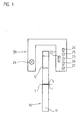
- FIG. 1 is shown in schematic form an embodiment of the position measuring device according to the invention in a sectional view.
- the variant of the position measuring device shown here serves to detect rotational movements of two mutually movable objects about the axis of rotation 1 and comprises a scale 10 and a scanning unit 20 which are each connected to one of the two objects.
- the measuring direction x in which the two objects are movable relative to each other, is rotationally symmetrical in the present case to the rotation axis 1 oriented.
- the scale 10 is formed as a part disc, which consists of a disc-shaped support member 11, on which a track 12 is arranged with an incremental graduation circular in the circumferential direction.
- the incremental division which in Fig. 1 can not be detected in detail, consists of a arranged in the measuring direction x, periodically with the incremental graduation period TP INC sequence of subregions with different optical properties.
- the subregions in this case have a longitudinal extent in a direction y, which is oriented perpendicular to the measuring direction x.
- the incremental graduation is in the form of transmitted-light phase division, that is to say the successive partial regions each have a different phase-shifting optical effect on the transmitted radiation beams;
- the carrier element 11 is made of glass.
- a light source 21 is arranged on the side of the scanning unit 20;
- the scanning unit 20 comprises scanning graduations 22.1, 22.2 as well as a plurality of detector elements 23-27, which serve to generate different scanning signals.
- Reference numeral 23 designates an incremental signal detector element indicated only schematically, which is used to detect the periodic incremental signals INC.
- the incremental signal detector element 23 can be designed in a known manner as a so-called structured detector arrangement or else as an arrangement with a plurality of individual photoelements.
- Reference numerals 24, 25, 26, 27 denote the reference pulse detector elements to which a plurality of reference pulse partial signals REF 1 -REF 4 are applied and from whose processing the reference pulse signal REF is ultimately generated, which will be explained in detail below.
- reference pulse detector elements 24-27 known photoelements come into consideration.
- the incremental signals INC and reference pulse signals REF generated by the position-measuring device are finally sent to a downstream evaluation unit (not shown), e.g. a numerical machine tool control, provided for further processing.
- a downstream evaluation unit e.g. a numerical machine tool control
- FIG. 2 shows a perspective schematic representation of the different scanning beam paths in the position measuring device according to the invention.
- the incident beam S is split by diffraction at the incremental graduation into two partial beams S +1 and S -1 , which propagate in two different spatial directions.
- the two partial beams S +1 and S -1 strike a respective scanning graduation 22.1, 22.2.
- the partial beams S +1 and S -1 are also deflected again by diffraction and in a detection plane, in which the incremental signal detector element 23 is arranged, for interference brought.
- the incremental signal detector element 23 is in the case of relative movement of scale and scanning unit, ie in the case of rotation about the rotation axis 1, a periodically modulated incremental signal INC, which can be further processed in a known manner.
- the inventive measures furthermore allow a reference pulse signal REF to be generated along at least one location or reference position x REF along the measurement path d.
- a reference pulse signal REF is generated along at least one location or reference position x REF along the measurement path d.
- the absolute reference can be established during the measurement, to which the subsequent incremental measurement is then referred.
- FIGS. 3a and 3b refer to a plan view of the scale 10 and an enlarged view thereof at the reference position x REF .
- the incremental graduation in the position measuring device consists of subregions TB1, TB2 arranged periodically with the incremental graduation period TP INC in the measuring direction x and having different optical properties.
- the subregions TB1, TB2 in this case have a longitudinal extent in a direction y, which is oriented perpendicular to the measuring direction x.
- the incremental graduation in a first section D 1 of the measuring section furthermore has a first transversal substructure, which deflects radiation beams impinging thereon in at least one first spatial direction.
- the first section D 1 extends over the left 180 ° circle segment of the graduated disk or incremental graduation.
- the incremental graduation has a second transversal substructure, the incident beam bundles deflects in at least a second spatial direction.
- the second spatial direction is different from the first spatial direction.
- the right 180 ° circle segment of the incremental graduation therefore represents the second section D 2 of the measuring path.
- the transversal substructures in the incremental graduation are each in the form of periodic structures with a defined deflection graduation period TP TRANS, 1 , TP TRANS . 2 along the direction y of the longitudinal extent of the subregions TB1, TB2 formed, in particular in FIG. 3b is recognizable.
- the first transversal substructure in the first section D1 in this case has a first deflection graduation period TP TRANS, 1 ;
- the second transversal substructure in the second section has a second deflection pitch period TP TRANS, 2 , which differs from the first deflection pitch period TP TRANS, 1 .
- the transversal substructure in the first section D 1 of the measuring section causes a deflection of the impinging beam R in a first spatial direction RR 1 .
- the beams deflected into the first spatial direction RR1 are designated by the reference symbol ST 1 .
- the transversal substructure in the second section D 2 of the measuring section effects a deflection of the impinging beam bundles S into a second spatial direction RR 2.
- the beams deflected into the second spatial direction RR2 are designated by the reference symbol ST 2 .
- FIG. 2 are illustrated in the two spatial directions RR1, RR2 deflected beam ST 1 , ST 2 , which occurs in practice only in the transition region between the two sections D 1 and D 2 for illustrative purposes.
- Reference pulse detector elements 24, 25 are respectively arranged in the two spatial directions RR1 and RR2 and detect the radiation beams deflected in these spatial directions RR1, RR2 and at which reference pulse partial signals REF 1 , REF 2 , from the processing of which the reference pulse signal REF can basically be generated.
- the transversal substructure in this section merely deflects into the first spatial direction RR 1 , ie the beam ST 1 results, which is the first Reference pulse detector element 24 applied. Only the first reference pulse detector element 24 registers in this measuring phase an incident radiation intensity and thus a first reference pulse partial signal REF 1 present at the output.
- the distracting transversal substructures of the incremental graduation used in the present example are designed as diffractive structures and in each case not only cause a deflection in the first or second spatial direction RR1, RR2.
- the first section D 1 in addition to the deflection of the beam S T1 in the first spatial direction, there is also a deflection of the beam S T4 into a fourth spatial direction RR4 in which a reference pulse signal detector element 27 is also arranged.
- the second section D 2 in addition to the deflection of the beam S T2 in the second spatial direction RR2 nor a deflection of a beam S T3 in a third spatial direction RR3, in which also a reference pulse signal detector element 26 is arranged.
- the first and fourth spatial directions RR1, RR4 and the second and third spatial directions RR2, RR3 thus correspond to the +1, respectively. and -1. Diffraction orders, in which by the respective transverse substructures of the two sections D 1 , D 2, a corresponding deflection takes place.
- the first and fourth reference pulse detector elements 24, 27 and the second and third reference pulse detector elements 25, 26 are connected together.
- FIG. 2 is spanned by the different spatial directions RR1 - RR4, in which a deflection of the beam takes place, a plane which is oriented perpendicular to the measuring direction x and parallel to the direction of the longitudinal extent y of the different sections TB1, TB2 of the incremental graduation.
- the incremental graduation is formed in the example described as a transmitted light division or phase grating.
- periodically arranged with the incremental graduation period TP INC subregions TB1 and TB2 thus exert respectively a different effect on the transmitted beam.
- the transversal substructure of the incremental graduation is formed by a corresponding design of the subregions TB1, TB2. Preferably, these have - as in FIG. 3b recognizable - periodic, sinusoidal contour boundaries in the direction of their longitudinal extent, ie in the y direction.
- the periodicity of the ideally sinusoidal contour boundaries corresponds to the respective transverse deflection graduation periods TP TRANS, 1 , TP TRANS , 2 . Because of this transversal substructure, in addition to the deflection or splitting of the beam bundles used for incremental signal generation in the measuring direction x, the desired transverse deflection of beam bundles also results for generating the reference pulse signal REF.
- a particular advantage of a sinusoidal contour limitation is that it ensures that the intensity of the incremental signal is only slightly affected by the generation of the reference pulse signal. The reason for this is the low field strength of the +/- 1. longitudinal diffraction orders at the locations of the transverse lattice structures.
- the expansion of the sinusoidal contour boundaries in the measuring direction x ie the modulation amplitude of the sine function, determines the distribution ratio of the light intensities for the sub-beams of the reference mark and the incremental signal sampling used. This division ratio is set as desired by selecting the modulation period of the sine function. It should also be noted here that as far as possible the distribution ratio set in the different subregions TB1 and TB2 does not differ as much as possible. In addition to the example of the FIG.
- 3b illustrated embodiment of a suitable transversal substructure in the incremental graduation are also still alternative variants in the context of the present invention can be used.
- a periodic transversal substructure in which the subregions of the incremental graduation have triangular contour boundaries along the y direction.
- the modulation amplitude of the contour boundary could be chosen so large that touching in the measuring direction adjacent transverse substructures and thus results in a cross grid with diamond-shaped structures.
- cylindrical lenses could also be used as substructures that deflect transversely to the measuring direction x in the respective subregions of the incremental graduation. Such cylindrical lenses can also be used to focus the transversely deflected diffraction orders on small detector elements. The zeroth diffraction orders used for the incremental signal generation are not focused or defocused.
- these parameters can also be selected elsewhere and adapted to the respective sampling configuration.
- the generation of so-called distance-coded reference marks is possible, etc.
- each reference position would be assigned a specific transition between differently deflecting transversal substructures, etc.
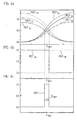
- FIGS. 4a-4c and 5 Let us explain in a first variant how the desired reference pulse signal REF is ultimately generated from the reference pulse sub-signals REF 1 -REF 4 generated in accordance with the invention in the present example.
- FIG. 5 it can be seen that in this embodiment the first and fourth reference pulse detector elements 24, 27 arranged in the first and fourth spatial directions are interconnected in such a way that a first reference pulse sum signal REF S1 results at the output of a first downstream current-voltage converter 28.1; Analogously thereto, the second and third reference pulse detector elements 25, 26 arranged in the second and third spatial directions are interconnected so that a second reference pulse sum signal REF S2 results at the output of the downstream, second current-voltage converter 28.2.
- FIG. 4a the course of the two reference pulse sum signals REF S1 , REF S2 in the range of the reference position x REF is shown.
- FIG. 4a can be seen from the first and second reference pulse sum signals REF S1 , REF S2 without further additional measures already obtained information in this regard, on which side of the reference position x REF the scanning unit is currently located.
- the two first and second reference pulse sum signals REF S1 , REF S2 can therefore also be evaluated as range signals. As long as the first reference pulse sum signal REF S1 is greater than the second reference pulse sum signal REF S2 , in the present example the scanning unit is to the left of the reference position x REF , whereas if the first reference pulse sum signal REF S1 is smaller than the second reference pulse sum signal REF S2 is, the scanning unit is to the right of the reference position x REF etc.
- two reference pulse auxiliary signals REF H1 , REF H2 are then formed by subsequent logical operations.
- the two comparator units 29.1, 29.2 are the two reference pulse auxiliary signals REF H1 , REF H2 , whose course in the range of the reference position x REF in FIG. 4b is shown.
- the reference pulse signal REF is finally produced by a logical AND connection with the aid of the logic element 31, which then results as a rectangular signal with a specific width b REF .
- FIG. 4c shows the resulting rectangular signal.
- the resulting width b REF set the reference pulse signal REF and adapt to the periodicity of the incremental signals generated in parallel.
- the generated first-sixth reference pulse sum signals can also be referred to as so-called range signals each clearly indicating the relative position of the scanning unit with respect to the reference position x REF .
- range signals can also be used to generate a reference pulse signal. Due to the transition region between first and second range signals , the reference position x REF is defined in this case. According to the invention it was therefore recognized that for generating a reference pulse signal, as it is based on the FIGS. 4a-4c and 5 has been explained, in principle, range signals can be used, which were generated alternatively to the manner explained above.
- processing of the input-side range signals preferably takes place analogously to the processing of the reference-pulse partial signals or sum signals.
- the amplification and attenuation of the range signals likewise takes place with defined amplification and attenuation factors. about Their choice can ultimately - as explained above - adjust the width of the resulting Referenzipulssignales.
- the first and second range signals each have a unique signal level in each of the two ranges, ie that the signal levels can be suitably distinguished, as for example for the first and second reference pulse sum signals REF S1 , REF S2 is the case in the above example.
- the generation of the first and second range signals can also be carried out as an alternative to the example explained above.
- the range signals can also be derived from a separate range track on the scale.
- the range track again comprises two partial tracks which are each designed to be complementary to one another and are, for example, fully transmissive on one side of the reference position x REF , while this is opaque in the area to the right of the reference position x REF .
- Each of the two partial tracks is scanned by a detector element for generating the range signals, so that even with such a configuration of scale and scanning unit range signals with the required curve in the range of the reference position x REF can be generated.
- a second variant for generating a reference pulse signal is described below with reference to FIGS. 6 . 7 and 8a - 8c explained.
- FIG. 6 again shows the device as in FIG. 2 has already been explained in principle. In the following, therefore, only the differences from the embodiment explained above will be discussed.
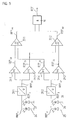
- FIG. 7 shows a block diagram with respect to the interconnection.
- the first and second reference pulse detector elements 24, 25 or the respective reference pulse partial signals REF 1 , REF 2 - respectively range signals - are interconnected, so that at the output of a first downstream current-voltage converter 128 Reference pulse sum signal REF S1 is present.
- the third and fourth reference pulse signal detector elements 26, 27 and the respective reference pulse sub-signals REF 3 , REF 4 - respectively range signals - so interconnected that at the output of the downstream second current-voltage converter 128.2 a signal results, the following is referred to as the second reference pulse sum signal REF S2 .
- the signal REF S2 is a signal which is substantially proportional to the sum of the signals REF 3 and REF 4 and can also be referred to as a reference pulse signal.
- amplifier units 129.1, 129.2 which are respectively downstream of the current-voltage converters 128.1, 128.2, the two signals REF S1 , REF S2 are amplified.
- At the output of the two amplifier units 129.1, 129.2 are the amplified first and second signals REF S and REF G , whose course in the range of the reference position x REF in the FIGS. 8a and 8b is shown.
- the signal REF S essentially has a constant signal level, while the signal level of the signal REF S changes greatly in the region of the reference position x REF .
- two trigger or reference signals TS1, TS2, each having constant signal levels, are derived from the signal REF G
- FIG. 8a are also shown and are used to generate the actual reference pulse signal REF at the intersections with the signal REF S.
- the resulting signal REF is finally in FIG. 8c shown.
- the circuit implementation of this variant for generating the reference pulse signal REF is off FIG. 7 visible;
- the reference pulse signal REF results at the output of the comparator unit 130, at whose inputs the signals REF G and REF S are present.
- the comparator unit 130 is formed in a known manner, for example, as a window comparator, wherein from the respective level of the applied signal REF G, the window width and thus the position of the two trigger signals TS1, TS2 is determined.
- the two reference pulse auxiliary signals could also be generated by the logical comparison of other signal combinations, etc ..
Abstract
Description
Die vorliegende Erfindung betrifft eine Positionsmesseinrichtung nach dem Oberbegriff des Anspruches 1. Desweiteren betrifft die vorliegende Erfindung ein Verfahren zum Betrieb einer Positionsmesseinrichtung nach dem Oberbegriff des Anspruches 19.The present invention relates to a position-measuring device according to the preamble of
Bekannte Positionsmesseinrichtungen liefern neben Inkrementalsignalen bezüglich des Relativversatzes zweier zueinander beweglicher Objekte oftmals auch sogenannte Referenzimpulssignale. Über diese Signale kann bei einer definierten Relativposition der zueinander beweglichen Objekte ein exakter Absolutbezug der Positionsmessung hergestellt werden. Zur Erzeugung der Referenzimpulssignale sind auf Seiten des Maßstabes der Positionsmesseinrichtung an ein oder mehreren Stellen Felder mit Referenzmarkierungen angeordnet. Bezüglich der Anordnung der Referenzmarkierungen auf dem Maßstab existieren eine Reihe von bekannten Möglichkeiten.Known position-measuring devices often provide so-called reference pulse signals in addition to incremental signals with respect to the relative offset of two mutually movable objects. By means of these signals, a precise absolute reference of the position measurement can be produced in the case of a defined relative position of the mutually movable objects. In order to generate the reference pulse signals, fields with reference markings are arranged on one or more locations on the scale of the position-measuring device. Regarding the arrangement of the reference marks on the scale, there are a number of known possibilities.
So ist beispielsweise aus der
Daneben ist es auch möglich, die Referenzmarkierungen unmittelbar in die Spur mit der Inkrementalteilung zu integrieren, wie dies etwa in der
Weitere Varianten bezüglich der Integration von Referenzmarkierungen in die Spur mit der Inkrementalteilung sind ferner aus der
Als problematisch bei der Integration von Referenzmarkierungen in die Inkrementalteilung erweist sich jedoch grundsätzlich, dass dadurch auch das periodische Inkrementalsignal an dieser Stelle gestört wird, da man gezwungen ist eine hinreichende Detektionssicherheit für das Referenzimpulssignal sicherzustellen. Insbesondere im Fall einer gewünschten hohen Interpolation des Inkrementalsignales, die wiederum ein möglichst gute Signalqualität desselben voraussetzt, ergeben sich Schwierigkeiten, wenn das Inkrementalsignal an der Referenzposition deutlich von einer idealen Signalform abweicht.As a problem with the integration of reference marks in the incremental graduation, however, proves in principle that thereby also the periodic incremental signal is disturbed at this point, since one is forced a sufficient detection reliability for the reference pulse signal sure. Particularly in the case of a desired high interpolation of the incremental signal, which in turn requires the best possible signal quality of the same, difficulties arise when the incremental signal at the reference position deviates significantly from an ideal signal form.
Desweiteren ist aus der
Eine erste Aufgabe der vorliegenden Erfindung ist es daher, eine Positionsmesseinrichtung zu schaffen, die eine Erzeugung eines Referenzimpulssignales aus einer Spur mit einer Inkrementalteilung ermöglicht. Hierbei soll die Inkrementalsignal-Erzeugung möglichst wenig gestört werden.A first object of the present invention is therefore to provide a position measuring device which enables generation of a reference pulse signal from a track having an incremental pitch. Here, the incremental signal generation should be disturbed as little as possible.
Desweiteren ist eine zweite Aufgabe der vorliegenden Erfindung, ein Verfahren zum Betrieb einer Positionsmesseinrichtung anzugeben, das insbesondere zur korrekten Erzeugung eines Referenzimpulssignales aus einer Spur mit Bereichssignalen geeignet ist.Furthermore, a second object of the present invention is to provide a method for operating a position-measuring device, which is particularly suitable for the correct generation of a reference pulse signal from a track with range signals.
Die erste Aufgabe wird gelöst durch eine Positionsmesseinrichtung mit den Merkmalen im kennzeichnenden Teil des Anspruches 1.The first object is achieved by a position-measuring device with the features in the characterizing part of
Vorteilhafte Ausführungsformen der erfindungsgemäßen Positionsmesseinrichtung ergeben sich aus den Maßnahmen, die in den von Anspruch 1 abhängigen Ansprüchen aufgeführt sind.Advantageous embodiments of the position-measuring device according to the invention result from the measures that are listed in the dependent of
Die zweite Aufgabe wird gelöst durch ein Verfahren mit den Merkmalen im kennzeichnenden Teil des Anspruches 19.The second object is achieved by a method having the features in the characterizing part of claim 19.
Vorteilhafte Ausführungsformen des erfindungsgemäßen Verfahrens zum Betrieb einer Positionsmesseinrichtung ergeben sich aus den Maßnahmen, die in den von Anspruch 19 abhängigen Ansprüchen aufgeführt sind.Advantageous embodiments of the method according to the invention for operating a position-measuring device result from the measures listed in the claims dependent on claim 19.
Erfindungsgemäß weisen in der Positionsmesseinrichtung nunmehr unterschiedliche Abschnitte der Inkrementalteilung entlang der Messstrecke unterschiedliche periodische Transversal-Substrukturen auf, die eine Ablenkung der auftreffenden Strahlenbündel in verschiedene Raumrichtungen bewirken. Hierbei sind jedem Abschnitt unterschiedliche Transversal-Substrukturen mit unterschiedlichen Ablenkwirkungen zugeordnet. Im Übergangsbereich zwischen benachbarten Abschnitten liegt eine Unstetigkeit bzgl. der optischen Ablenkwirkung der Transversal-Substrukturen vor, die zur Erzeugung des Referenzimpulssignales an dieser Stelle, d.h. der Referenzposition, genutzt wird. Hierzu sind auf Seiten der Abtasteinheit mindestens zwei Referenzimpuls-Detektorelemente in den verschiedenen Raumrichtungen angeordnet. An den Referenzimpuls-Detektorelementen liegen Referenzimpuls-Teilsignale an, aus deren Verarbeitung das gewünschte Referenzimpulssignal resultiert.According to the invention, different sections of the incremental graduation along the measuring path now have different periodic transverse substructures in the position measuring device, which effect a deflection of the impinging radiation bundles in different spatial directions. In this case, each section is assigned different transversal substructures with different deflection effects. In the transition region between adjacent sections, there is discontinuity in the optical deflection effect of the transverse substructures used to generate the reference pulse signal at that location, i. the reference position is used. For this purpose, at least two reference pulse detector elements are arranged in the different spatial directions on the part of the scanning unit. Reference pulse partial signals are present at the reference pulse detector elements, the processing of which results in the desired reference pulse signal.
Durch diese Art der Referenzimpulssignal-Erzeugung ist gewährleistet, dass die periodische Inkrementalteilung auch an der Referenzposition nicht in ihrer Periodizität gestört wird und demzufolge auch das resultierende Inkrementalsignal von der Erzeugung des Referenzimpulssignales nicht gestört wird. Insbesondere erleidet auch das Inkrementalsignal aufgrund der erfindungsgemäßen Erzeugung des Referenzimpulssignales keine unerwünschten Intensitätseinbußen.This type of reference pulse signal generation ensures that the periodic incremental division is not disturbed in its periodicity even at the reference position, and consequently that the resulting incremental signal is not disturbed by the generation of the reference pulse signal. In particular, the incremental signal also suffers no unwanted intensity losses due to the generation of the reference pulse signal according to the invention.
Neben den Vorteilen eines aus der Inkrementalteilung abgeleiteten Referenzimpulssignales hinsichtlich geringer Baugröße der Positionsmesseinrichtung und unkritischer Montage ergeben sich aufgrund der erfindungsgemäßen Maßnahmen weitere Vorteile.In addition to the advantages of a reference pulse signal derived from the incremental graduation with regard to small size of the position-measuring device and non-critical mounting, further advantages result due to the inventive measures.
So kann nunmehr ohne weitere Zusatzmaßnahmen aus den Referenzimpuls-Teilsignalen auch eine Information diesbezüglich erzeugt werden, auf welcher Seite der Referenzmarkierung bzw. in welchem Bereich sich die Abtasteinheit gerade befindet. Die Referenzimpuls-Teilsignale können demzufolge auch als sog. Bereichssignale ausgewertet werden. Ferner kann durch die Art und Weise der Verarbeitung der Referenzimpuls-Teilsignale eine gewünschte Breite des resultierenden rechteckförmigen Referenzimpulssignales definiert eingestellt und auf die Signalperiode des Inkrementalsignales abgestimmt werden.Thus, now without further additional measures from the reference pulse sub-signals also information in this regard are generated on which side of the reference marking or in which area the scanning unit is currently located. The reference pulse sub-signals can therefore also be evaluated as so-called range signals. Further, by the manner of processing the reference pulse sub-signals, a desired width of the resulting rectangular reference pulse signal can be set in a defined manner and tuned to the signal period of the incremental signal.
Im Fall der Erzeugung mindestens eines ersten und eines zweiten Bereichssignales und aus dem erfolgenden Vergleich zwischen dem ersten Bereichssignal oder davon abgeleiteten weiteren Bereichssignalen mit dem zweiten Bereichssignal oder hiervon abgeleiteten weiteren Bereichssignalen ist hierbei ein Referenzimpulssignal erzeugbar.In the case of generating at least a first and a second range signal and from the successful comparison between the first range signal or further range signals derived therefrom with the second range signal or further range signals derived therefrom, a reference pulse signal can be generated.
Selbstverständlich lassen sich die erfindungsgemäßen Maßnahmen sowohl in rotatorischen als auch in linearen Positionsmesseinrichtungen einsetzen.Of course, the inventive measures can be used both in rotary and in linear position measuring devices.
Desweiteren lassen sich sowohl Auflicht-Positionsmesseinrichtungen als auch Durchlicht-Positionsmesseinrichtungen erfindungsgemäß ausgestalten.Furthermore, incident-light position-measuring devices as well as transmitted-light position-measuring devices can be configured according to the invention.
Weitere Vorteile sowie Einzelheiten der vorliegenden Erfindung ergeben sich aus der nachfolgenden Beschreibung eines Ausführungsbeispieles anhand der beiliegenden Figuren.Further advantages and details of the present invention will become apparent from the following description of an embodiment with reference to the accompanying figures.
Dabei zeigt
Figur 1- eine seitliche Ansicht eines Ausführungsbeispieles der erfindungsgemäßen Positionsmesseinrichtung;
Figur 2- eine schematische räumliche Darstellung des Abtaststrahlenganges im Ausführungsbeispiel der
Figur 1 - Figur 3a und 3b
- jeweils eine Draufsicht auf den Maßstab aus
Figur 1; - Figur 4a - 4c
- verschiedene Signaldiagramme, anhand der eine erste Variante der erfindungsgemäßen Erzeugung des Referenzimpulssignales erläutert wird;
Figur 5- eine Blockschaltbild-Darstellung zur Erläuterung der ersten Variante zur Erzeugung des Referenzimpulssignales;
Figur 6- eine schematische räumliche Darstellung des Abtaststrahlenganges eines weiteren Ausführungsbeispieles zur Erläuterung einer zweiten Variante zur Erzeugung des Referenzimpulssignales;
- Figur 7
- eine Blockschaltbild-Darstellung zur Erläuterung der zweiten Variante zur Erzeugung des Referenzimpulssignales;
- Figur 8a - 8c
- verschiedene Signaldiagramme, anhand der eine zweite Variante der erfindungsgemäßen Erzeugung des Referenzimpulssignales erläutert wird.
- FIG. 1
- a side view of an embodiment of the position measuring device according to the invention;
- FIG. 2
- a schematic spatial representation of the scanning beam path in the embodiment of
FIG. 1 ; - Figure 3a and 3b
- in each case a plan view of the scale of Figure 1;
- Figure 4a - 4c
- various signal diagrams, based on a first variant of the generation of the reference pulse signal according to the invention is explained;
- FIG. 5
- a block diagram representation for explaining the first variant for generating the reference pulse signal;
- FIG. 6
- a schematic spatial representation of the scanning beam path of another embodiment for explaining a second variant for generating the reference pulse signal;
- FIG. 7
- a block diagram representation for explaining the second variant for generating the reference pulse signal;
- FIGS. 8a-8c
- various signal diagrams, based on a second variant of the generation of the reference pulse signal according to the invention will be explained.
In
Der Maßstab 10 ist als Teilscheibe ausgebildet, die aus einem scheibenförmigen Trägerelement 11 besteht, auf der eine Spur 12 mit einer Inkrementalteilung kreisförmig in Umfangsrichtung angeordnet ist. Die Inkrementalteilung, die in
Im vorliegenden Beispiel ist die Inkrementalteilung als Durchlicht-Phasenteilung ausgebildet, d.h. die aufeinanderfolgenden Teilbereiche weisen jeweils eine unterschiedlich phasenschiebende optische Wirkung auf die durchtretenden Strahlenbündel auf; das Trägerelement 11 besteht aus Glas. Auf Seiten der Abtasteinheit 20 ist eine Lichtquelle 21 angeordnet; desweiteren umfasst die Abtasteinheit 20 Abtastteilungen 22.1, 22.2 sowie mehrere Detektorelemente 23 - 27, die zur Erzeugung unterschiedlicher Abtastsignale dienen. Mit dem Bezugszeichen 23 wird hierbei ein lediglich schematisiert angedeutetes Inkrementalsignal-Detektorelement bezeichnet, das zur Erfassung der periodischen Inkrementalsignale INC dient. Das Inkrementalsignal-Detektorelement 23 kann in bekannnter Art und Weise als sog. strukturierte Detektoranordnung ausgebildet sein oder aber als Anordnung mit mehreren einzelnen Photoelementen. Mit Hilfe des Inkrementalsignal-Detektorelementes 23 werden in bekannter Art und Weise vier um jeweils 90° bzw. drei um je 120° phasenverschobene Inkrementalsignale erzeugt, die wiederum zu zwei um 90° phasenverschobenen Inkremental-Ausgangssignalen verschaltet werden. Nachfolgend sei der Einfachheit halber jedoch lediglich von periodischen Inkrementalsignalen INC die Rede.In the present example, the incremental graduation is in the form of transmitted-light phase division, that is to say the successive partial regions each have a different phase-shifting optical effect on the transmitted radiation beams; the
Mit den Bezugszeichen 24, 25, 26, 27 seien die Referenzimpuls-Detektorelemente bezeichnet, an denen mehrere Referenzimpuls-Teilsignale REF1 - REF4 anliegen und aus deren Verarbeitung letztlich das Referenzimpulssignal REF erzeugt wird, was nachfolgend noch im Detail erläutert wird. Als Referenzimpuls-Detektorelemente 24 - 27 kommen bekannte Photoelemente in Betracht.
Die von der Positionsmesseinrichtung erzeugten Inkrementalsignale INC und Referenzimpulssignale REF werden schließlich einer - nicht dargestellten - nachgeordneten Auswerteeinheit, z.B. einer numerischen Werkzeugmaschinensteuerung, zur Weiterverarbeitung zur Verfügung gestellt.The incremental signals INC and reference pulse signals REF generated by the position-measuring device are finally sent to a downstream evaluation unit (not shown), e.g. a numerical machine tool control, provided for further processing.
Zur detaillierten Erläuterung der erfindungsgemäßen Erzeugung des Referenzimpulssignales sei nunmehr auf die Beschreibung der folgenden Figuren verwiesen.
Das von der - in
Zur Erzeugung der Inkrementalsignale INC wird das auftreffende Strahlenbündel S durch Beugung an der Inkrementalteilung in zwei Teilstrahlenbündel S+1 und S-1 aufgespalten, die sich in zwei unterschiedlichen Raumrichtungen ausbreiten. Auf Seiten der Abtasteinheit treffen die beiden Teilstrahlenbündel S+1 und S-1 auf jeweils eine Abtastteilung 22.1, 22.2. Von den Abtastteilungen 22.1, 22.2 werden die Teilstrahlenbündel S+1 und S-1 ebenfalls wieder durch Beugung abgelenkt und in einer Detektionsebene, in der der das Inkrementalsignal-Detektorelement 23 angeordnet ist, zur Interferenz gebracht. Am Inkrementalsignal-Detektorelement 23 liegt im Fall der Relativbewegung von Maßstab und Abtasteinheit, d.h. im Fall der Rotation um die Drehachse 1, ein periodisch moduliertes Inkrementalsignal INC an, welches in bekannter Art und Weise weiterverarbeitetet werden kann.To generate the incremental signals INC, the incident beam S is split by diffraction at the incremental graduation into two partial beams S +1 and S -1 , which propagate in two different spatial directions. On the side of the scanning unit, the two partial beams S +1 and S -1 strike a respective scanning graduation 22.1, 22.2. Of the scanning divisions 22.1, 22.2, the partial beams S +1 and S -1 are also deflected again by diffraction and in a detection plane, in which the incremental
Neben periodischen Inkrementalsignalen INC lässt sich durch die erfindungsgemäßen Maßnahmen desweiteren auch an mindestens einer Stelle bzw. Referenzposition xREF entlang der Messstrecke d ein Referenzimpulssignal REF erzeugen. Mit Hilfe des Referenzimpulssignales REF kann der Absolutbezug während der Messung hergestellt werden, auf den dann die nachfolgende Inkrementalmessung bezogen wird.In addition to periodic incremental signals INC, the inventive measures furthermore allow a reference pulse signal REF to be generated along at least one location or reference position x REF along the measurement path d. With the aid of the reference pulse signal REF, the absolute reference can be established during the measurement, to which the subsequent incremental measurement is then referred.
Zu diesem Zweck ist eine bestimmte Ausbildung der Inkrementalteilung vorgesehen, um durch eine Unstetigkeit bzgl. einer optischen Eigenschaft an mindestens einer Stelle bzw. Referenzposition ein Referenzimpulssignal REF zu erzeugen. Zur weiteren Erläuterung der vorliegenden Erfindung sei an dieser Strelle auch auf die
Grundsätzlich besteht die Inkrementalteilung in der erfindungsgemäßen Positionsmesseinrichtung aus periodisch mit der Inkremental-Teilungsperiode TPINC in Messrichtung x angeordneten Teilbereichen TB1, TB2 mit unterschiedlichen optischen Eigenschaften. Die Teilbereiche TB1, TB2 besitzen hierbei eine Längsausdehnung in einer Richtung y, die senkrecht zur Messrichtung x orientiert ist.
Im vorliegenden Beispiel weist die Inkrementalteilung in einem ersten Abschnitt D1 der Messtrecke desweiteren eine erste Transversal-Substruktur auf, die darauf auftreffende Strahlenbündel in mindestens eine erste Raumrichtung ablenkt. Beim dargestellten Ausführungsbeispiel in den
In the present example, the incremental graduation in a first section D 1 of the measuring section furthermore has a first transversal substructure, which deflects radiation beams impinging thereon in at least one first spatial direction. In the illustrated embodiment in the
Die Transversal-Substrukturen in der Inkrementalteilung sind jeweils als periodische Strukturen mit einer definierten Ablenk-Teilungsperiode TPTRANS,1, TPTRANS.2 entlang der Richtung y der Längsausdehnung der Teilbereiche TB1, TB2 ausgebildet, wie insbesondere in
Wie aus der Darstellung in
In den beiden Raumrichtungen RR1 und RR2 sind jeweils Referenzimpuls-Detektorelemente 24, 25 angeordnet, die die in diese Raumrichtungen RR1, RR2 abgelenkten Strahlenbündel detektieren und an denen Referenzimpuls-Teilsignale REF1, REF2 anliegen, aus deren Verarbeitung sich das Referenzimpulssignal REF grundsätzlich erzeugen lässt.Reference
Nachfolgend sei das zugrundeliegende Prinzip der Erzeugung des Referenzimpulssignales REF an der Referenzposition xREF im vorliegenden Beispiel erläutert.
Solange das von der Lichtquelle kommende Strahlenbündel S ausschließlich den ersten Abschnitt D1 der Inkrementalteilung abtastet bzw. durchläuft, erfolgt durch die Transversal-Substruktur in diesem Abschnitt lediglich eine Ablenkung in die erste Raumrichtung RR1, d.h. es resultiert das Strahlenbündel ST1, welches das erste Referenzimpuls-Detektorelement 24 beaufschlagt. Nur das erste Referenzimpuls-Detektorelement 24 registriert in dieser Mess-Phase eine einfallende Strahlungsintensität und damit ein am Ausgang anliegendes erstes Referenzimpuls-Teilsignal REF1. Im Fall der Abtastung des zweiten Abschnittes D2 der Inkrementalteilung liegen genau umgekehrte Verhältnisse vor, d.h. lediglich das zweite Referenzimpuls-Detektorelement 25 in der zweiten Raumrichtung RR2 registriert die einfallende Strahlungsintensität des Strahlenbündels ST2 bzw. an dessen Ausgang liegt dann das zweite Referenzimpuls-Teilsignal REF2 an. Im Übergangsbereich zwischen den beiden Abschnitten D1 und D2, respektive an der Referenzposition xREF, liegt somit ein charakteristischer Signalverlauf bzgl. der beiden Referenzimpuls-Teilsignale REF1, REF2 vor, der zur erfindungsgemäßen Erzeugung eines Referenzimpulssignales REF ausgenutzt werden kann.Hereinafter, the underlying principle of generating the reference pulse signal REF at the reference position x REF in the present example will be explained.
As long as the beam S coming from the light source scans or traverses exclusively the first section D 1 of the incremental graduation, the transversal substructure in this section merely deflects into the first spatial direction RR 1 , ie the beam ST 1 results, which is the first Reference
Im Beispiel der
Darüberhinaus kann selbstverständlich auch vorgesehen werden, die jeweilige Messstrecke in noch mehr Abschnitte zu zerlegen und an den Übergangsbereichen zwischen den verschiedenen Abschnitten jeweils Referenzimpulssignale zu erzeugen.In addition, it can of course also be provided to split the respective measuring section into even more sections and to generate respective reference pulse signals at the transition regions between the different sections.
Die im vorliegenden Beispiel verwendeten, ablenkenden Transversal-Substrukturen der Inkrementalteilung sind als beugende Strukturen ausgebildet und bewirken jeweils nicht nur eine Ablenkung in die erste oder zweite Raumrichtung RR1, RR2. Es erfolgt im ersten Abschnitt D1 neben der Ablenkung des Strahlenbündels ST1 in die erste Raumrichtung desweiteren noch eine Ablenkung des Strahlenbündels ST4 in eine vierte Raumrichtung RR4, in der ebenfalls ein Referenzimpulssignal-Detektorelement 27 angeordnet ist. Analog hierzu resultiert im zweiten Abschnitt D2 neben der Ablenkung des Strahlenbündels ST2 in die zweite Raumrichtung RR2 noch eine Ablenkung eines Strahlenbündels ST3 in eine dritte Raumrichtung RR3, in der ebenfalls ein Referenzimpulssignal-Detektorelement 26 angeordnet ist. Die erste und vierte Raumrichtung RR1, RR4 sowie die zweite und dritte Raumrichtung RR2, RR3 entsprechen somit jeweils den +1. und -1. Beugungsordnungen, in die durch die jeweiligen Transversal-Substrukturen der beiden Abschnitte D1, D2 eine entsprechende Ablenkung erfolgt. Zur weiteren Signalverarbeitung werden die ersten und vierten Referenzimpuls-Detektorelemente 24, 27 sowie die zweiten und dritten Referenzimpuls-Detektorelemente 25, 26 zusammengeschaltet.The distracting transversal substructures of the incremental graduation used in the present example are designed as diffractive structures and in each case not only cause a deflection in the first or second spatial direction RR1, RR2. In the first section D 1, in addition to the deflection of the beam S T1 in the first spatial direction, there is also a deflection of the beam S T4 into a fourth spatial direction RR4 in which a reference pulse
Wie aus
Die Inkrementalteilung ist im beschriebenen Beispiel als Durchlichtteilung bzw. Phasengitter ausgebildet. Die in
An dieser Stelle sei darauf hingewiesen, dass im Rahmen der vorliegenden Erfindung selbstverständlich alternativ auch Amplitudengitter bzw. -strukturen verwendet werden können. Ebenso ist es selbstverständlich möglich, alternativ ein Auflichtsystem erfindungsgemäß zu realisieren.At this point, it should be noted that in the context of the present invention, of course, alternatively also amplitude gratings or structures can be used. Likewise, it is of course possible to realize an incident light system according to the invention as an alternative.
Die Transversal-Substruktur der Inkremental-Teilung wird durch eine entsprechende Ausgestaltung der Teilbereiche TB1, TB2 gebildet. Vorzugsweise weisen diese - wie in
So könnte z.B. auch eine periodische Transversal-Substruktur eingesetzt werden, bei der die Teilbereiche der Inkrementalteilung dreieckförmige Konturbegrenzungen entlang der y-Richtung aufweisen.The transversal substructure of the incremental graduation is formed by a corresponding design of the subregions TB1, TB2. Preferably, these have - as in
For example, it would also be possible to use a periodic transversal substructure in which the subregions of the incremental graduation have triangular contour boundaries along the y direction.
Ferner könnte die Modulationsamplitude der Konturbegrenzung so groß gewählt werden, dass sich in Messrichtung benachbarte Transversal-Substrukturen berühren und derart ein Kreuzgitter mit rautenförmigen Strukturen resultiert.
Desweiteren könnten in den jeweiligen Teilbereichen der Inkrementalteilung auch Zylinderlinsen als transversal zur Messrichtung x ablenkende Substrukturen eingesetzt werden. Derartige Zylinderlinsen können auch zur Fokussierung der transversal abgelenkten Beugungsordnungen auf kleine Detektorelemente eingesetzt werden. Die für die Inkrementalsignalerzeugung genutzten nullten Beugungsordnungen werden hierbei nicht fokussiert bzw. defokussiert.Further, the modulation amplitude of the contour boundary could be chosen so large that touching in the measuring direction adjacent transverse substructures and thus results in a cross grid with diamond-shaped structures.
Furthermore, cylindrical lenses could also be used as substructures that deflect transversely to the measuring direction x in the respective subregions of the incremental graduation. Such cylindrical lenses can also be used to focus the transversely deflected diffraction orders on small detector elements. The zeroth diffraction orders used for the incremental signal generation are not focused or defocused.
In einem möglichen Ausführungsform der vorliegenden Erfindung wird die Inkrementalteilungsperiode TPINC = 4µm und die beiden transversalen Ablenk-Teilungsperioden TPTRANS,1= 3.5µm, TPTRANS,2 = 4.5µm gewählt. Selbstverständlich könnnen diese Parameter auch anderweitig gewählt und an die jeweilige Abtastkonfiguration angepasst werden.In one possible embodiment of the present invention, the incremental graduation period TP INC = 4 μm and the two transverse deflection graduation periods TP TRANS, 1 = 3.5 μm, TP TRANS, 2 = 4.5 μm are selected. Of course, these parameters can also be selected elsewhere and adapted to the respective sampling configuration.
In weiteren alternativen Ausführungsformen zum erläuterten Beispiel kann desweiteren vorgesehen werden, entlang der jeweiligen Messstrecke noch an mehr als zwei Referenzpositionen Referenzimpulssignale zu erzeugen. Auch die Erzeugung sog. abstandscodierter Referenzmarken ist möglich usw..In further alternative embodiments to the described example, it is furthermore possible to generate reference pulse signals at more than two reference positions along the respective measuring path. The generation of so-called distance-coded reference marks is possible, etc.
Ferner kann auch vorgesehen werden, mehr als lediglich zwei unterschiedlich ablenkende Transversal-Substrukturen einzusetzen. So könnte etwa insbesondere im Fall mehrerer erzeugter Referenzimpulssignale entlang der Messstrecke derart auch eine eindeutige Codierung bzw. Identifikation der jeweiligen Referenzimpulssignale erfolgen. Jeder Referenzposition wäre in diesem Fall ein bestimmter Übergang zwischen unterschiedlich ablenkenden Transversal-Substrukturen eindeutig zugeordnet etc..Furthermore, it can also be provided to use more than just two differently deflecting transversal substructures. Thus, for example, in the case of a plurality of generated reference pulse signals along the measuring path, a clear coding or identification of the respective reference pulse signals could also take place in this way. In this case, each reference position would be assigned a specific transition between differently deflecting transversal substructures, etc.
Schließlich sei an dieser Stelle erwähnt, dass es im vorliegenden Ausführungsbeispiel auch möglich ist, stets eine Information diesbezüglich zu erzeugen, die angibt, auf welcher Seite einer Referenzposition sich die Abtasteinheit gerade befindet bzw. in welchem Bereich der Messstrecke sich die Abtasteinheit gerade befindet. Dies kann durch das Auslesen der jeweiligen Referenzimpulssignal-Detektorelemente 24, 25, 26, 27 erfolgen. So ist etwa offensichtlich, dass im oben erläuterten Beispiel im Fall eines aussschließlich detektierten ersten Referenzimpuls-Teilsignales REF1 sich die Abtasteinheit im ersten Abschnitt D1 befindet, analog hierzu befindet sich die Abtasteinheit im Fall eines ausschließlich detektierten zweiten Referenzimpuls-Teilsignales REF im zweiten Abschnitt D2 usw.. Die Referenzimpuls-Teilsignale REF1, REF2 können demzufolge auch als sog. Bereichssignale ausgewertet werden.Finally, it should be mentioned at this point that in the present embodiment it is also possible to always generate information in this regard, indicating on which side of a reference position the scanning unit is currently located or in which area of the measuring section the scanning unit is currently located. This can be done by reading the respective reference pulse
Anhand der
Wie aus
Wie ebenfalls aus
Die beiden ersten und zweiten Referenzimpuls-Summensignalen REFS1, REFS2 können demzufolge auch als Bereichssignale ausgewertet werden. Solange das erste Referenzimpuls-Summensignal REFS1 größer als das zweite Referenzimpuls-Summensignal REFS2 ist, befindet sich im vorliegenden Beispiel die Abtasteinheit demzufolge links von der Referenzposition xREF, wenn hingegen erste Referenzimpuls-Summensignal REFS1 kleiner als das zweite Referenzimpuls-Summensignal REFS2 ist, befindet sich die Abtasteinheit rechts von der Referenzposition xREF etc..The two first and second reference pulse sum signals REF S1 , REF S2 can therefore also be evaluated as range signals. As long as the first reference pulse sum signal REF S1 is greater than the second reference pulse sum signal REF S2 , in the present example the scanning unit is to the left of the reference position x REF , whereas if the first reference pulse sum signal REF S1 is smaller than the second reference pulse sum signal REF S2 is, the scanning unit is to the right of the reference position x REF etc.
Es sei an dieser Stelle erwähnt, dass grundsätzlich jeweils nur eines der beiden Referenzimpuls-Detektorelemente 24 oder 27 bzw. der Referenzimpuls-Detektorelemente 25, 26 erforderlich wäre, um auf erfindungsgemäße Art und Weise ein Referenzimpulssignal REF zu erzeugen. Die Verwendung von jeweils zwei Referenzimpuls-Detektorelementen und die entsprechende Verschaltung derselben gemäß
Die beiden ersten und zweiten Referenzimpuls-Summensignale REFS1, REFS2 werden anschließend mithilfe von jeweils zwei Verstärkereinheiten 29.1, 29.2 mit einem vorgegebenem Verstärkungsfaktor V = (1 + ε) verstärkt, so dass am Ausgang der beiden Verstärkereinheiten 29.1, 29.2 dritte und sechste Referenzimpuls-Summensignale REFS3, REFS6 anliegen. Desweiteren werden die beiden Referenzimpuls-Summensignale REFS1, REFS2 über zwei Abschwächereinheiten 29.3, 29.4 mit einem vorgegebenem Abschwächungsfaktor A = (1 - ε) abgeschwächt, so dass am Ausgang der beiden Abschwächereinheiten 29.3, 29.4 vierte und fünfte Referenzimpuls-Summensignale REFS4, REFS5 anliegen. In
Aus den verschiedenen Referenzimpuls-Summensignalen REFS3 - REFS6 werden daraufhin durch nachfolgende logische Verknüpfungen zwei Referenzimpuls-Hilfssignale REFH1, REFH2 gebildet. Zu diesem Zweck werden das dritte und fünfte Referenzimpuls-Summensignal REFS3, REFS5 den beiden Eingängen einer ersten Komparatoreinheit 29.1 zugeführt und das vierte und sechste Referenzimpuls-Summensignal REFS4, REFS6 den Eingängen einer zweiten Komparatoreinheit 29.2 zugeführt. Am Ausgang der beiden Komparatoreinheiten 29.1, 29.2 liegen die beiden Referenzimpuls-Hilfssignale REFH1, REFH2 an, deren Verlauf im Bereich der Referenzposition xREF in
Mit Hilfe der Komparatoreinheiten 29.1, 29.2 erfolgt die Erzeugung der beiden Referenzimpuls-Hilfssignale REFH1, REFH2 aus den vier eingangsseitig anliegenden verstärkten bzw. abgeschwächten Referenzimpuls-Summensignalen REFS3 - REFS6 auf Basis der folgenden Vergleichsoperationen: ![]()
und 
![]()
and
Aus den beiden derart gebildeten Referenzimpuls-Hilfssignalen REFH1, REFH2 wird abschließend durch eine logische UND-Verknüpfung mit Hilfe des Verknüpfungsgliedes 31 das Referenzimpulssignal REF erzeugt, das sich dann als Rechtecksignal mit einer bestimmten Breite bREF ergibt. In Figur 4c ist das derart resultierende Rechtecksignal dargestellt.From the two reference pulse auxiliary signals REF H1 , REF H2 thus formed, the reference pulse signal REF is finally produced by a logical AND connection with the aid of the
Wie aus den
Im erläuterten Beispiel können wie oben erläutert die erzeugten ersten - sechsten Referenzimpuls-Summensignale auch als sog. Bereichssignale fungieren, die jeweils eindeutig die Relativlage der Abtasteinheit in Bezug auf die Referenzposition xREF kennzeichnen. Wie bereits eingangs erwähnt und aus der
Vorzugsweise erfolgt auch im erfindungsgemäßen Verfahren eine Verarbeitung der eingangsseitigen Bereichssignale analog zu der Verarbeitung der Referenzimpuls-Teilsignale bzw. -Summensignale. Dies bedeutet, dass auch aus dem zweiten Bereichssignal im vorliegenden Beispiel durch Abschwächung und Verstärkung fünfte und sechste Bereichssignale resultieren, die dann wiederum mit dem ersten, dritten oder vierten Bereichssignal verglichen werden, um ein Referenzimpulssignal zu erzeugen.In the method according to the invention, too, processing of the input-side range signals preferably takes place analogously to the processing of the reference-pulse partial signals or sum signals. This means that also from the second range signal in the present example by attenuation and amplification fifth and sixth range signals result, which are then in turn compared with the first, third or fourth range signal to generate a reference pulse signal.
Die Verstärkung und Abschwächung der Bereichssignale erfolgt ebenfalls wiederum mit definierten Verstärkungs- und Abschwächungsfaktoren. Über deren Wahl lässt sich letztlich - wie oben erläutert - die Breite des resultierenden Referenzipulssignales einstellen.The amplification and attenuation of the range signals likewise takes place with defined amplification and attenuation factors. about Their choice can ultimately - as explained above - adjust the width of the resulting Referenzipulssignales.
Als Anforderung hinsichtlich der zu erzeugenden Bereichssignale ist lediglich aufzuführen, dass das erste und zweite Bereichssignal jeweils einen eindeutigen Signalpegel in jedem der beiden Bereiche aufweist, d.h. dass sich die Signalpegel geeignet unterscheiden lassen, wie dies etwa für die ersten und zweiten Referenzimpuls-Summensignale REFS1, REFS2 im obigen Beispiel der Fall ist.As a requirement with regard to the range signals to be generated, it is merely to be stated that the first and second range signals each have a unique signal level in each of the two ranges, ie that the signal levels can be suitably distinguished, as for example for the first and second reference pulse sum signals REF S1 , REF S2 is the case in the above example.
Die Erzeugung der ersten und zweiten Bereichssignale kann jedoch auch alternativ zum oben erläuterten Beispiel erfolgen. So können etwa die Bereichssignale auch aus einer separaten Bereichsspur auf dem Maßstab abgeleitet werden. Die Bereichsspur umfasst z.B. wiederum zwei Teilspuren, die jeweils komplementär zueinader ausgebildet sind und z.B. auf einer Seite der Referenzposition xREF voll durchlässig ist, während diese im Bereich rechts von der Referenzposition xREF opak ausgebildet ist. Jede der beiden Teilspuren wird von einem Detektorelement zur Erzeugung der Bereichssignale abgetastet, so dass sich auch bei einer derartigen Ausgestaltung von Maßstab und Abtasteinheit Bereichssignale mit dem erforderlichen Verlauf im Bereich der Referenzposition xREF erzeugen lassen.However, the generation of the first and second range signals can also be carried out as an alternative to the example explained above. Thus, for example, the range signals can also be derived from a separate range track on the scale. The range track, for example, again comprises two partial tracks which are each designed to be complementary to one another and are, for example, fully transmissive on one side of the reference position x REF , while this is opaque in the area to the right of the reference position x REF . Each of the two partial tracks is scanned by a detector element for generating the range signals, so that even with such a configuration of scale and scanning unit range signals with the required curve in the range of the reference position x REF can be generated.
Eine zweite Variante zur Erzeugung eines Referenzimpulssignales sei nachfolgend anhand der
Wie aus
Die schaltungstechnische Realisierung dieser Variante zur Erzeugung des Referenzimpulssignales REF ist aus
Neben den erläuterten Ausführungsbeispielen existieren selbstverständlich noch weitere alternative Ausgestaltungsmöglichkeiten der vorliegenden Erfindung.In addition to the illustrated embodiments, of course, there are other alternative embodiments of the present invention.
So wäre es etwa möglich, im ersten erläuterten Beispiel lediglich das erste erzeugte Referenzimpuls-Summensignal REFS1 zu verstärken und abzuschwächen und anschließend durch logische Vergleichsoperationen mit dem zweiten, unveränderten Referenzimpuls-Summensignal ein Referenzimpulssignal definierter Breite zu erzeugen.For example, in the first illustrated example, it would be possible to amplify and attenuate only the first generated reference pulse sum signal REF S1 , and then to generate a reference pulse signal of defined width by logical comparison operations with the second, unchanged reference pulse sum signal.
Desweiteren könnten die beiden Referenzimpuls-Hilfssignale auch durch den logischen Vergleich anderer Signalkombinationen erzeugt werden usw..Furthermore, the two reference pulse auxiliary signals could also be generated by the logical comparison of other signal combinations, etc ..
Claims (25)
- A position measuring device for generating periodic incremental signals and at least one reference pulse signal consisting of- a gauge (10) comprising a track (12), in which a periodic incremental scale comprising a defined incremental scale period (TPINC) is disposed, which extends in a direction of measurement (x) and wherein the track (12) encompasses a discontinuity with respect to an optical property for generating a reference pulse signal (REF) in at least one defined reference position (xREF) and- a scanner unit (20), which can be displaced across a defined measuring length (D) relative to the gauge (10) in the direction of measurement (x) and which, in addition to a light source (21), comprises a plurality of detector elements (23, 24, 25, 26, 27) for the photoelectric scanning of the incremental scale,characterized in that- in a first section (D1) of the measuring length (D), the incremental scale has a first transverse substructure, which deflects incident ray beams (S) in at least a first direction of space (RR1) and in that, in a second section (D2) of the measuring length, the incremental scale has a second transverse substructure, which deflects incident ray beams (S) in at least a second direction of space (RR2), which differs from the first direction of space (RR1) so that in the transition region between the first and the second section (D1, D2) a discontinuity with respect to the optical deflection effect of the transverse substructures of the incremental scale is at hand and- on the sides of the scanner unit (20) one or a plurality of reference pulse detector elements (24, 25, 26, 27) are in each case disposed in the different directions of space (RR1, RR2), which are supplied with partial reference pulse signals (REF1-REF4), which are processed to result in the reference pulse signal (REF).
- The position measuring device according to claim 1, characterized in that the incremental scale consists of partial regions (TB1, TB2), which are disposed periodically with the incremental scale period (TPINC) in the direction of measurement (x) and which comprise different optical properties, wherein the partial regions (TB1, TB2) have a longitudinal extension in a direction (y), which is oriented at right angles to the direction of measurement (x) and wherein the transverse substructures are embodied in each case as periodic structures comprising a defined deflection scale period (TPTRANS,1, TPTRANS,2) along the direction (y) of the longitudinal extension of the partial regions (TB1, TB2).
- The position measuring device according to claim 2, characterized in that the first transverse substructure encompasses a first deflection scale period (TPTRANS,1) and the second transverse substructure encompasses a second deflection scale period (TPTRANS,2), which differs from the first deflection scale period (TPTRANS,1).
- The position measuring device according to claim 2, characterized in that- the first transverse substructure causes a deflection in the first direction of space (RR1) and in a further fourth direction of space (RR4), which differs from the first direction of space (RR1) and- the second transverse substructure causes a deflection in the second direction of space (RR2) and in a further third direction of space (RR3), which differs from the second direction of space (RR2).
- The position measuring device according to claim 4, characterized in that the directions of space (RR1-RR4), in which a deflection of the ray beams (ST1-ST4) result, stretch a plane, which is oriented at right angles to the direction of measurement (x) and parallel to the direction (y) of the longitudinal extension of the partial regions (TB1, TB2) of the incremental scale.
- The position measuring device according to claim 4, characterized in that the first and fourth or the second and third directions of space (RR1-RR4) correspond to the directions, in which a deflection in the +/-1 deflection order results through the transverse substructure comprising the respective deflection scale period (TPTRANS,1, TPTRANS,2).
- The position measuring device according to claim 2, characterized in that the partial regions of the incremental scale encompass sinusoidal contour limitations in the direction (y) of their longitudinal extension.
- The position measuring device according to claim 2, characterized in that the partial regions of the incremental scale encompass triangular contour limitations in the direction (y) of their longitudinal extension.
- The position measuring device according to claim 1, characterized in that the incremental scale is disposed on a discoidal support element (11) so as to be circular in peripheral direction and in that the first and second sections (D1, D2) of the incremental scale represent two adjacent segments of a circle.
- The position measuring device according to claim 9, characterized in that the two segments of a circle in each case extend across 180° so that reference pulse signals (REF) can be generated on two opposite reference positions (xREF) along the peripheral direction.
- The position measuring device according to claim 1, characterized in that the incremental scale is embodied as a phase grid.
- The position measuring device according to claim 1, characterized in that the incremental scale is embodied as a transmitted light scale.
- The position measuring device according to claim 1, characterized in that an illumination of the incremental scale takes place by means of a collimated ray beam (S) comprising a small diameter.
- The position measuring device according to claim 4, characterized in that- in the first and fourth direction of space (RR1, RR4) first and fourth reference pulse detector elements (24, 27) are disposed, which are connected in such a manner that a first reference pulse summed signal (REFS1) results from the supplied first and fourth reference pulse scale signals (REF1, REF4) and- in the second and third directions of space (RR2, RR3) second and third reference pulse detector elements (25, 26) are disposed, which are connected in such a manner that a second reference pulse summed signal (REFS2) results from the supplied second and third reference pulse scale signals (REF2, REF3),- wherein the first and second reference pulse summed signal (REFS1, REFS2) is processed to result in the reference pulse signal (REF).
- The position measuring device according to claim 14, characterized in that- further third and fourth reference pulse summed signals (REFS3, REFS4) result from the first reference pulse summed signal (REFS1) by means of amplification and attenuation and- further fifth and sixth reference pulse summed signals (REFS5, REFS6) result from the second reference pulse summed signal (REFS2) by means of attenuation and amplification and- the reference pulse signal (REF) results from the logical connection of the third, fourth, fifth and sixth reference pulse summed signals (REFS3, REFS4, REFS5, REFS6).
- The position measuring device according to claim 15, characterized in that the logical connection of the third, fourth, fifth and sixth reference pulse summed signals (REFS3, REFS4, REFS5, REFS6) result in two reference pulse auxiliary signals (REFH1, REFH2), from the logical AND gating of which results a reference pulse signal (REF) in the form of a rectangular signal comprising a defined width (bREF).
- The position measuring device according to claim 4, characterized in that- in the first and second direction of space (RR1, RR2) first and second reference pulse detector elements (24, 25) are disposed, which are connected in such a manner that the supplied first and second reference pulse scale signals (REF1, REF2) result in a first reference pulse summed signal (REFS1) and- in the third and fourth directions of space (PR3, PR4) third and fourth reference pulse detector elements (26, 27) are disposed, which are connected in such a manner that a second reference pulse summed signal (REFS2) results from the supplied third and fourth reference pulse scale signals (REF3, REF4),- wherein the first and second reference pulse summed signal (REFS1, REFS2) are processed to result in the reference pulse signal (REF).
- The position measuring device according to claim 17, characterized in that the first and second reference pulse summed signals (REFS1, REFS2) are supplied after an amplification at the inputs of a comparator unit (130) and the reference pulse signal (REF) results at the output thereof.
- A method for operating a position measuring device, in particular for generating a reference pulse signal on at least one reference position along a measuring length, wherein first and second region signals can be derived from a track on a gauge, said measuring signals clearly characterize in each case the relative position of the scanner unit, which is displaceable with respect to the gauge, in relation to the reference position and the reference position is defined in at least one region signal by means of the transition region,
characterized in
that a reference pulse signal (REF) can be generated from the comparison between the first region signal or further signals derived therefrom with the second region signal or further signals derived therefrom. - The method according to claim 19, characterized in that- at least the first region signal is amplified and attenuated so that third and fourth region signal result therefrom and- a reference pulse signal (REF) is generated from the comparison between the first, third or fourth region signal with the second region signal or further region signals derived therefrom.
- The method according to claim 20, characterized in that the second region signal is amplified and attenuated so that fifth and sixth region signals result therefrom and that a reference pulse signal (REF) is generated from the comparison between the first, third or fourth region signal with the second, fifth or sixth region signal.
- The method according to claim 20, characterized in that the first and second region signal in each case encompasses a clear signal level for each of the two regions.
- The method according to claim 20, characterized in that defined amplification and attenuation factors (A, V) are chosen for amplifying and attenuating the region signals.
- The method according to claim 23, characterized in that the width (b) of the resulting reference pulse signal (REF) is set by means of the selection of the amplification and attenuation factors (A, V).
- The method according to claim 19, characterized in that, for the purpose of generating the reference pulse signal (REF), a first signal (REFS), which is derived from two region signals (REF1, REF2), is supplied to a comparator unit (130) and wherein the first signal (REFS) is highly amplified in the region of the reference position (xREF) and that a second signal (REFG), which is also derived from two region signals (REF3, REF4) is further supplied to the comparator unit (130) and wherein the second signal (REFG) encompasses a substantially constant signal level in the region of the reference position (xREF).
Applications Claiming Priority (3)
| Application Number | Priority Date | Filing Date | Title |
|---|---|---|---|
| DE10143185 | 2001-09-04 | ||
| DE10143185 | 2001-09-04 | ||
| PCT/EP2002/009767 WO2003021185A1 (en) | 2001-09-04 | 2002-09-02 | Position measuring system and method for operating such a position measuring system |
Publications (2)
| Publication Number | Publication Date |
|---|---|
| EP1427985A1 EP1427985A1 (en) | 2004-06-16 |
| EP1427985B1 true EP1427985B1 (en) | 2008-11-19 |
Family
ID=7697588
Family Applications (1)
| Application Number | Title | Priority Date | Filing Date |
|---|---|---|---|
| EP02774545A Expired - Lifetime EP1427985B1 (en) | 2001-09-04 | 2002-09-02 | Position measuring system and method for operating such a position measuring system |
Country Status (7)
| Country | Link |
|---|---|
| US (1) | US7161139B2 (en) |
| EP (1) | EP1427985B1 (en) |
| JP (1) | JP3881339B2 (en) |
| CN (1) | CN1250933C (en) |
| AT (1) | ATE414890T1 (en) |
| DE (2) | DE10241038A1 (en) |
| WO (1) | WO2003021185A1 (en) |
Families Citing this family (9)
| Publication number | Priority date | Publication date | Assignee | Title |
|---|---|---|---|---|
| US20040262502A1 (en) * | 2003-06-26 | 2004-12-30 | Xerox Corporation | Position encoder |
| DE10346380B4 (en) * | 2003-09-26 | 2014-01-16 | Dr. Johannes Heidenhain Gmbh | Position measuring device |
| DE102008049140A1 (en) * | 2008-09-26 | 2010-04-01 | Dr. Johannes Heidenhain Gmbh | Arrangement and method for generating a reference pulse for a position measuring device |
| EP3222975B1 (en) * | 2016-03-24 | 2018-09-12 | The Swatch Group Research and Development Ltd. | Detection circuit for inductive motion sensor |
| EP3255384B1 (en) * | 2016-06-07 | 2018-11-28 | Dr. Johannes Heidenhain GmbH | Scale and a position measuring device |
| DE102016211150A1 (en) * | 2016-06-22 | 2017-12-28 | Dr. Johannes Heidenhain Gmbh | Optical position measuring device |
| DE102016214456A1 (en) * | 2016-08-04 | 2018-02-08 | Dr. Johannes Heidenhain Gesellschaft Mit Beschränkter Haftung | Position measuring device and method for operating a position measuring device |
| CN107187582B (en) * | 2017-07-31 | 2019-10-29 | 中国商用飞机有限责任公司 | A kind of flap slat control crank |
| DE102018200449A1 (en) * | 2018-01-12 | 2019-07-18 | Dr. Johannes Heidenhain Gmbh | Position measuring device |
Family Cites Families (12)
| Publication number | Priority date | Publication date | Assignee | Title |
|---|---|---|---|---|
| SE379241B (en) * | 1974-01-15 | 1975-09-29 | Aga Ab | |
| US4263506A (en) * | 1978-12-21 | 1981-04-21 | Hewlett-Packard Company | Pulse generating apparatus |
| DE3536466A1 (en) | 1985-10-12 | 1987-04-16 | Bodenseewerk Geraetetech | ZERO IMPULSE GENERATOR FOR GENERATING AN IMPULSE WHEN A PRESET LOCATION OF A CARRIER IS REACHED |
| GB8729066D0 (en) | 1987-12-12 | 1988-01-27 | Renishaw Plc | Opto-electronic scale-reading apparatus |
| US5064290A (en) * | 1987-12-12 | 1991-11-12 | Renishaw Plc | Opto-electronic scale-reading apparatus wherein phase-separated secondary orders of diffraction are generated |
| US4866269A (en) * | 1988-05-19 | 1989-09-12 | General Motors Corporation | Optical shaft position and speed sensor |
| DE4111873C2 (en) | 1991-04-11 | 1995-05-11 | Boehringer Werkzeugmaschinen | Measuring device on a machine tool for determining the respective location of a movable component |
| ATE192566T1 (en) * | 1994-02-23 | 2000-05-15 | Heidenhain Gmbh Dr Johannes | POSITION MEASURING DEVICE |
| JP3395339B2 (en) * | 1994-03-31 | 2003-04-14 | ソニー・プレシジョン・テクノロジー株式会社 | Fixed point detector |
| EP0896206B1 (en) * | 1997-08-07 | 2002-12-11 | Dr. Johannes Heidenhain GmbH | Read-out unit for an optical position measuring device |
| JP3808192B2 (en) | 1997-11-19 | 2006-08-09 | 株式会社ソキア | Movement amount measuring apparatus and movement amount measuring method |
| JP4724282B2 (en) * | 1999-10-12 | 2011-07-13 | キヤノン株式会社 | Rotation angle detector |
-
2002
- 2002-09-02 JP JP2003525220A patent/JP3881339B2/en not_active Expired - Fee Related
- 2002-09-02 CN CN02817339.2A patent/CN1250933C/en not_active Expired - Fee Related
- 2002-09-02 WO PCT/EP2002/009767 patent/WO2003021185A1/en active Application Filing
- 2002-09-02 AT AT02774545T patent/ATE414890T1/en not_active IP Right Cessation
- 2002-09-02 DE DE10241038A patent/DE10241038A1/en not_active Withdrawn
- 2002-09-02 DE DE50213034T patent/DE50213034D1/en not_active Expired - Lifetime
- 2002-09-02 EP EP02774545A patent/EP1427985B1/en not_active Expired - Lifetime
- 2002-09-02 US US10/488,640 patent/US7161139B2/en not_active Expired - Fee Related
Also Published As
| Publication number | Publication date |
|---|---|
| JP2005502036A (en) | 2005-01-20 |
| CN1250933C (en) | 2006-04-12 |
| US20040232320A1 (en) | 2004-11-25 |
| CN1551973A (en) | 2004-12-01 |
| EP1427985A1 (en) | 2004-06-16 |
| DE50213034D1 (en) | 2009-01-02 |
| DE10241038A1 (en) | 2003-03-20 |
| ATE414890T1 (en) | 2008-12-15 |
| JP3881339B2 (en) | 2007-02-14 |
| US7161139B2 (en) | 2007-01-09 |
| WO2003021185A1 (en) | 2003-03-13 |
Similar Documents
| Publication | Publication Date | Title |
|---|---|---|
| EP1002219B1 (en) | Optical position measuring device | |
| EP1407231B1 (en) | Position measuring device | |
| EP2063230B1 (en) | Optical positioning device | |
| DE19962278A1 (en) | Position measuring device | |
| EP1923672A2 (en) | Position measuring device | |
| DE3417176A1 (en) | PHOTOELECTRICAL MEASURING DEVICE | |
| EP0669519B1 (en) | Position measuring device | |
| EP1427985B1 (en) | Position measuring system and method for operating such a position measuring system | |
| EP1524503B1 (en) | Optical encoder | |
| EP3527951B1 (en) | Optical positioning device | |
| EP0747674B1 (en) | Photo-electric position measuring device | |
| EP1867960A1 (en) | Optical positioning device | |
| EP0763715B1 (en) | Device to filter overtones from signals | |
| DE10020575A1 (en) | Scanning unit for an optical position measuring device | |
| EP2963391A1 (en) | Position measuring device | |
| DE102014215633A1 (en) | Position measuring device | |
| DE10346380B4 (en) | Position measuring device | |
| DE19716058B4 (en) | Optical position measuring device | |
| EP0434973B1 (en) | Opto-electronic position measuring device | |
| DE102020134604B4 (en) | Device and method for position determination | |
| DE202005002622U1 (en) | Optical position sensor has reference scale with zones of different reflectivity and sensor plate of different transmission to generate reference pulse | |
| EP2730895B1 (en) | Optical positioning device | |
| DE10043828B4 (en) | Scanning unit for an optical position-measuring device | |
| DE10353808B4 (en) | Measuring graduation for a position measuring device and position measuring device | |
| DE102008046793A1 (en) | Optical position measuring device |
Legal Events
| Date | Code | Title | Description |
|---|---|---|---|
| PUAI | Public reference made under article 153(3) epc to a published international application that has entered the european phase |
Free format text: ORIGINAL CODE: 0009012 |
|
| 17P | Request for examination filed |
Effective date: 20040405 |
|
| AK | Designated contracting states |
Kind code of ref document: A1 Designated state(s): AT BE BG CH CY CZ DE DK EE ES FI FR GB GR IE IT LI LU MC NL PT SE SK TR |
|
| GRAP | Despatch of communication of intention to grant a patent |
Free format text: ORIGINAL CODE: EPIDOSNIGR1 |
|
| GRAS | Grant fee paid |
Free format text: ORIGINAL CODE: EPIDOSNIGR3 |
|
| GRAA | (expected) grant |
Free format text: ORIGINAL CODE: 0009210 |
|
| AK | Designated contracting states |
Kind code of ref document: B1 Designated state(s): AT BE BG CH CY CZ DE DK EE ES FI FR GB GR IE IT LI LU MC NL PT SE SK TR |
|
| REG | Reference to a national code |
Ref country code: GB Ref legal event code: FG4D Free format text: NOT ENGLISH |
|
| REG | Reference to a national code |
Ref country code: CH Ref legal event code: EP |
|
| REG | Reference to a national code |
Ref country code: IE Ref legal event code: FG4D Free format text: LANGUAGE OF EP DOCUMENT: GERMAN |
|
| REF | Corresponds to: |
Ref document number: 50213034 Country of ref document: DE Date of ref document: 20090102 Kind code of ref document: P |
|
| PG25 | Lapsed in a contracting state [announced via postgrant information from national office to epo] |
Ref country code: ES Free format text: LAPSE BECAUSE OF FAILURE TO SUBMIT A TRANSLATION OF THE DESCRIPTION OR TO PAY THE FEE WITHIN THE PRESCRIBED TIME-LIMIT Effective date: 20090301 |
|
| NLV1 | Nl: lapsed or annulled due to failure to fulfill the requirements of art. 29p and 29m of the patents act | ||
| PG25 | Lapsed in a contracting state [announced via postgrant information from national office to epo] |
Ref country code: NL Free format text: LAPSE BECAUSE OF FAILURE TO SUBMIT A TRANSLATION OF THE DESCRIPTION OR TO PAY THE FEE WITHIN THE PRESCRIBED TIME-LIMIT Effective date: 20081119 Ref country code: FI Free format text: LAPSE BECAUSE OF FAILURE TO SUBMIT A TRANSLATION OF THE DESCRIPTION OR TO PAY THE FEE WITHIN THE PRESCRIBED TIME-LIMIT Effective date: 20081119 |
|
| REG | Reference to a national code |
Ref country code: IE Ref legal event code: FD4D |
|
| PG25 | Lapsed in a contracting state [announced via postgrant information from national office to epo] |
Ref country code: BG Free format text: LAPSE BECAUSE OF FAILURE TO SUBMIT A TRANSLATION OF THE DESCRIPTION OR TO PAY THE FEE WITHIN THE PRESCRIBED TIME-LIMIT Effective date: 20090219 Ref country code: EE Free format text: LAPSE BECAUSE OF FAILURE TO SUBMIT A TRANSLATION OF THE DESCRIPTION OR TO PAY THE FEE WITHIN THE PRESCRIBED TIME-LIMIT Effective date: 20081119 Ref country code: DK Free format text: LAPSE BECAUSE OF FAILURE TO SUBMIT A TRANSLATION OF THE DESCRIPTION OR TO PAY THE FEE WITHIN THE PRESCRIBED TIME-LIMIT Effective date: 20081119 Ref country code: IE Free format text: LAPSE BECAUSE OF FAILURE TO SUBMIT A TRANSLATION OF THE DESCRIPTION OR TO PAY THE FEE WITHIN THE PRESCRIBED TIME-LIMIT Effective date: 20081119 |
|
| PG25 | Lapsed in a contracting state [announced via postgrant information from national office to epo] |
Ref country code: SE Free format text: LAPSE BECAUSE OF FAILURE TO SUBMIT A TRANSLATION OF THE DESCRIPTION OR TO PAY THE FEE WITHIN THE PRESCRIBED TIME-LIMIT Effective date: 20090219 Ref country code: CZ Free format text: LAPSE BECAUSE OF FAILURE TO SUBMIT A TRANSLATION OF THE DESCRIPTION OR TO PAY THE FEE WITHIN THE PRESCRIBED TIME-LIMIT Effective date: 20081119 Ref country code: PT Free format text: LAPSE BECAUSE OF FAILURE TO SUBMIT A TRANSLATION OF THE DESCRIPTION OR TO PAY THE FEE WITHIN THE PRESCRIBED TIME-LIMIT Effective date: 20090420 |
|
| PLBE | No opposition filed within time limit |
Free format text: ORIGINAL CODE: 0009261 |
|
| STAA | Information on the status of an ep patent application or granted ep patent |
Free format text: STATUS: NO OPPOSITION FILED WITHIN TIME LIMIT |
|
| PG25 | Lapsed in a contracting state [announced via postgrant information from national office to epo] |
Ref country code: SK Free format text: LAPSE BECAUSE OF FAILURE TO SUBMIT A TRANSLATION OF THE DESCRIPTION OR TO PAY THE FEE WITHIN THE PRESCRIBED TIME-LIMIT Effective date: 20081119 |
|
| 26N | No opposition filed |
Effective date: 20090820 |
|
| BERE | Be: lapsed |
Owner name: DR. JOHANNES HEIDENHAIN G.M.B.H. Effective date: 20090930 |
|
| PG25 | Lapsed in a contracting state [announced via postgrant information from national office to epo] |
Ref country code: MC Free format text: LAPSE BECAUSE OF NON-PAYMENT OF DUE FEES Effective date: 20090930 |
|
| REG | Reference to a national code |
Ref country code: CH Ref legal event code: PL |
|
| REG | Reference to a national code |
Ref country code: FR Ref legal event code: ST Effective date: 20100531 |
|
| PG25 | Lapsed in a contracting state [announced via postgrant information from national office to epo] |
Ref country code: FR Free format text: LAPSE BECAUSE OF NON-PAYMENT OF DUE FEES Effective date: 20090930 |
|
| PG25 | Lapsed in a contracting state [announced via postgrant information from national office to epo] |
Ref country code: BE Free format text: LAPSE BECAUSE OF NON-PAYMENT OF DUE FEES Effective date: 20090930 |
|
| PG25 | Lapsed in a contracting state [announced via postgrant information from national office to epo] |
Ref country code: CH Free format text: LAPSE BECAUSE OF NON-PAYMENT OF DUE FEES Effective date: 20090930 Ref country code: GR Free format text: LAPSE BECAUSE OF FAILURE TO SUBMIT A TRANSLATION OF THE DESCRIPTION OR TO PAY THE FEE WITHIN THE PRESCRIBED TIME-LIMIT Effective date: 20090220 Ref country code: LI Free format text: LAPSE BECAUSE OF NON-PAYMENT OF DUE FEES Effective date: 20090930 |
|
| PG25 | Lapsed in a contracting state [announced via postgrant information from national office to epo] |
Ref country code: AT Free format text: LAPSE BECAUSE OF NON-PAYMENT OF DUE FEES Effective date: 20090902 |
|
| PG25 | Lapsed in a contracting state [announced via postgrant information from national office to epo] |
Ref country code: IT Free format text: LAPSE BECAUSE OF FAILURE TO SUBMIT A TRANSLATION OF THE DESCRIPTION OR TO PAY THE FEE WITHIN THE PRESCRIBED TIME-LIMIT Effective date: 20081119 |
|
| PG25 | Lapsed in a contracting state [announced via postgrant information from national office to epo] |
Ref country code: LU Free format text: LAPSE BECAUSE OF NON-PAYMENT OF DUE FEES Effective date: 20090902 |
|
| PG25 | Lapsed in a contracting state [announced via postgrant information from national office to epo] |
Ref country code: TR Free format text: LAPSE BECAUSE OF FAILURE TO SUBMIT A TRANSLATION OF THE DESCRIPTION OR TO PAY THE FEE WITHIN THE PRESCRIBED TIME-LIMIT Effective date: 20081119 |
|
| PG25 | Lapsed in a contracting state [announced via postgrant information from national office to epo] |
Ref country code: CY Free format text: LAPSE BECAUSE OF FAILURE TO SUBMIT A TRANSLATION OF THE DESCRIPTION OR TO PAY THE FEE WITHIN THE PRESCRIBED TIME-LIMIT Effective date: 20081119 |
|
| PGFP | Annual fee paid to national office [announced via postgrant information from national office to epo] |
Ref country code: GB Payment date: 20160920 Year of fee payment: 15 |
|
| GBPC | Gb: european patent ceased through non-payment of renewal fee |
Effective date: 20170902 |
|
| PG25 | Lapsed in a contracting state [announced via postgrant information from national office to epo] |
Ref country code: GB Free format text: LAPSE BECAUSE OF NON-PAYMENT OF DUE FEES Effective date: 20170902 |
|
| PGFP | Annual fee paid to national office [announced via postgrant information from national office to epo] |
Ref country code: DE Payment date: 20200925 Year of fee payment: 19 |
|
| REG | Reference to a national code |
Ref country code: DE Ref legal event code: R119 Ref document number: 50213034 Country of ref document: DE |
|
| PG25 | Lapsed in a contracting state [announced via postgrant information from national office to epo] |
Ref country code: DE Free format text: LAPSE BECAUSE OF NON-PAYMENT OF DUE FEES Effective date: 20220401 |