EP2963380B2 - Contrôle sans contact d'une soudure bout à bout - Google Patents
Contrôle sans contact d'une soudure bout à bout Download PDFInfo
- Publication number
- EP2963380B2 EP2963380B2 EP14175829.2A EP14175829A EP2963380B2 EP 2963380 B2 EP2963380 B2 EP 2963380B2 EP 14175829 A EP14175829 A EP 14175829A EP 2963380 B2 EP2963380 B2 EP 2963380B2
- Authority
- EP
- European Patent Office
- Prior art keywords
- sensor
- weld seam
- pipe
- weld
- pipe ends
- Prior art date
- Legal status (The legal status is an assumption and is not a legal conclusion. Google has not performed a legal analysis and makes no representation as to the accuracy of the status listed.)
- Active
Links
Images


Classifications
-
- B—PERFORMING OPERATIONS; TRANSPORTING
- B29—WORKING OF PLASTICS; WORKING OF SUBSTANCES IN A PLASTIC STATE IN GENERAL
- B29C—SHAPING OR JOINING OF PLASTICS; SHAPING OF MATERIAL IN A PLASTIC STATE, NOT OTHERWISE PROVIDED FOR; AFTER-TREATMENT OF THE SHAPED PRODUCTS, e.g. REPAIRING
- B29C65/00—Joining or sealing of preformed parts, e.g. welding of plastics materials; Apparatus therefor
- B29C65/02—Joining or sealing of preformed parts, e.g. welding of plastics materials; Apparatus therefor by heating, with or without pressure
-
- B—PERFORMING OPERATIONS; TRANSPORTING
- B29—WORKING OF PLASTICS; WORKING OF SUBSTANCES IN A PLASTIC STATE IN GENERAL
- B29C—SHAPING OR JOINING OF PLASTICS; SHAPING OF MATERIAL IN A PLASTIC STATE, NOT OTHERWISE PROVIDED FOR; AFTER-TREATMENT OF THE SHAPED PRODUCTS, e.g. REPAIRING
- B29C65/00—Joining or sealing of preformed parts, e.g. welding of plastics materials; Apparatus therefor
- B29C65/78—Means for handling the parts to be joined, e.g. for making containers or hollow articles, e.g. means for handling sheets, plates, web-like materials, tubular articles, hollow articles or elements to be joined therewith; Means for discharging the joined articles from the joining apparatus
- B29C65/7841—Holding or clamping means for handling purposes
-
- B—PERFORMING OPERATIONS; TRANSPORTING
- B29—WORKING OF PLASTICS; WORKING OF SUBSTANCES IN A PLASTIC STATE IN GENERAL
- B29C—SHAPING OR JOINING OF PLASTICS; SHAPING OF MATERIAL IN A PLASTIC STATE, NOT OTHERWISE PROVIDED FOR; AFTER-TREATMENT OF THE SHAPED PRODUCTS, e.g. REPAIRING
- B29C65/00—Joining or sealing of preformed parts, e.g. welding of plastics materials; Apparatus therefor
- B29C65/82—Testing the joint
- B29C65/8253—Testing the joint by the use of waves or particle radiation, e.g. visual examination, scanning electron microscopy, or X-rays
-
- B—PERFORMING OPERATIONS; TRANSPORTING
- B29—WORKING OF PLASTICS; WORKING OF SUBSTANCES IN A PLASTIC STATE IN GENERAL
- B29C—SHAPING OR JOINING OF PLASTICS; SHAPING OF MATERIAL IN A PLASTIC STATE, NOT OTHERWISE PROVIDED FOR; AFTER-TREATMENT OF THE SHAPED PRODUCTS, e.g. REPAIRING
- B29C66/00—General aspects of processes or apparatus for joining preformed parts
- B29C66/01—General aspects dealing with the joint area or with the area to be joined
- B29C66/02—Preparation of the material, in the area to be joined, prior to joining or welding
- B29C66/022—Mechanical pre-treatments, e.g. reshaping
- B29C66/0224—Mechanical pre-treatments, e.g. reshaping with removal of material
- B29C66/02245—Abrading, e.g. grinding, sanding, sandblasting or scraping
-
- B—PERFORMING OPERATIONS; TRANSPORTING
- B29—WORKING OF PLASTICS; WORKING OF SUBSTANCES IN A PLASTIC STATE IN GENERAL
- B29C—SHAPING OR JOINING OF PLASTICS; SHAPING OF MATERIAL IN A PLASTIC STATE, NOT OTHERWISE PROVIDED FOR; AFTER-TREATMENT OF THE SHAPED PRODUCTS, e.g. REPAIRING
- B29C66/00—General aspects of processes or apparatus for joining preformed parts
- B29C66/01—General aspects dealing with the joint area or with the area to be joined
- B29C66/05—Particular design of joint configurations
- B29C66/10—Particular design of joint configurations particular design of the joint cross-sections
- B29C66/11—Joint cross-sections comprising a single joint-segment, i.e. one of the parts to be joined comprising a single joint-segment in the joint cross-section
- B29C66/114—Single butt joints
- B29C66/1142—Single butt to butt joints
-
- B—PERFORMING OPERATIONS; TRANSPORTING
- B29—WORKING OF PLASTICS; WORKING OF SUBSTANCES IN A PLASTIC STATE IN GENERAL
- B29C—SHAPING OR JOINING OF PLASTICS; SHAPING OF MATERIAL IN A PLASTIC STATE, NOT OTHERWISE PROVIDED FOR; AFTER-TREATMENT OF THE SHAPED PRODUCTS, e.g. REPAIRING
- B29C66/00—General aspects of processes or apparatus for joining preformed parts
- B29C66/50—General aspects of joining tubular articles; General aspects of joining long products, i.e. bars or profiled elements; General aspects of joining single elements to tubular articles, hollow articles or bars; General aspects of joining several hollow-preforms to form hollow or tubular articles
- B29C66/51—Joining tubular articles, profiled elements or bars; Joining single elements to tubular articles, hollow articles or bars; Joining several hollow-preforms to form hollow or tubular articles
- B29C66/52—Joining tubular articles, bars or profiled elements
- B29C66/522—Joining tubular articles
- B29C66/5221—Joining tubular articles for forming coaxial connections, i.e. the tubular articles to be joined forming a zero angle relative to each other
-
- B—PERFORMING OPERATIONS; TRANSPORTING
- B29—WORKING OF PLASTICS; WORKING OF SUBSTANCES IN A PLASTIC STATE IN GENERAL
- B29C—SHAPING OR JOINING OF PLASTICS; SHAPING OF MATERIAL IN A PLASTIC STATE, NOT OTHERWISE PROVIDED FOR; AFTER-TREATMENT OF THE SHAPED PRODUCTS, e.g. REPAIRING
- B29C66/00—General aspects of processes or apparatus for joining preformed parts
- B29C66/90—Measuring or controlling the joining process
- B29C66/97—Checking completion of joining or correct joining by using indications on at least one of the joined parts
- B29C66/974—Checking completion of joining or correct joining by using indications on at least one of the joined parts by checking the bead or burr form
-
- B—PERFORMING OPERATIONS; TRANSPORTING
- B29—WORKING OF PLASTICS; WORKING OF SUBSTANCES IN A PLASTIC STATE IN GENERAL
- B29D—PRODUCING PARTICULAR ARTICLES FROM PLASTICS OR FROM SUBSTANCES IN A PLASTIC STATE
- B29D23/00—Producing tubular articles
- B29D23/001—Pipes; Pipe joints
-
- G—PHYSICS
- G01—MEASURING; TESTING
- G01B—MEASURING LENGTH, THICKNESS OR SIMILAR LINEAR DIMENSIONS; MEASURING ANGLES; MEASURING AREAS; MEASURING IRREGULARITIES OF SURFACES OR CONTOURS
- G01B11/00—Measuring arrangements characterised by the use of optical techniques
- G01B11/24—Measuring arrangements characterised by the use of optical techniques for measuring contours or curvatures
-
- G—PHYSICS
- G01—MEASURING; TESTING
- G01N—INVESTIGATING OR ANALYSING MATERIALS BY DETERMINING THEIR CHEMICAL OR PHYSICAL PROPERTIES
- G01N21/00—Investigating or analysing materials by the use of optical means, i.e. using sub-millimetre waves, infrared, visible or ultraviolet light
- G01N21/84—Systems specially adapted for particular applications
- G01N21/88—Investigating the presence of flaws or contamination
- G01N21/8851—Scan or image signal processing specially adapted therefor, e.g. for scan signal adjustment, for detecting different kinds of defects, for compensating for structures, markings, edges
-
- G—PHYSICS
- G01—MEASURING; TESTING
- G01N—INVESTIGATING OR ANALYSING MATERIALS BY DETERMINING THEIR CHEMICAL OR PHYSICAL PROPERTIES
- G01N21/00—Investigating or analysing materials by the use of optical means, i.e. using sub-millimetre waves, infrared, visible or ultraviolet light
- G01N21/84—Systems specially adapted for particular applications
- G01N21/88—Investigating the presence of flaws or contamination
- G01N21/95—Investigating the presence of flaws or contamination characterised by the material or shape of the object to be examined
- G01N21/952—Inspecting the exterior surface of cylindrical bodies or wires
-
- G—PHYSICS
- G01—MEASURING; TESTING
- G01N—INVESTIGATING OR ANALYSING MATERIALS BY DETERMINING THEIR CHEMICAL OR PHYSICAL PROPERTIES
- G01N2201/00—Features of devices classified in G01N21/00
- G01N2201/06—Illumination; Optics
- G01N2201/062—LED's
Definitions
- the invention relates to a device and a method for the contactless inspection of a butt weld of plastic pipes and fittings, wherein the device has a support device, a lighting device and at least one sensor, wherein the pipe ends are welded by means of a known butt welding process and a contactless inspection of the weld seam and optional inspection of the pipe ends or fitting ends before welding is carried out by means of a sensor.
- the sensor carrier is arranged movably or rotatably on the carrier device, thereby the sensor carrier can be rotated on the carrier device by rotatable about an axis, the support device forming a fixed base.
- the invention is characterized by the fact that the sensor carrier can rotate 360° around the pipe or the weld. This allows the sensor mounted on the sensor carrier to also move around the pipe and can record or inspect the entire weld seam or the pipe ends before welding.
- the sensor carrier preferably has a C-shape. This allows for easy positioning of the sensor carrier around the pipe circumference by moving the C-shaped sensor carrier over the pipe circumference, since the opening of the C-shape is so large that the largest pipe diameter that can be checked with the device according to the invention can be pushed through the opening of the C-shape or the sensor carrier can be pushed over the pipe.
- the pipe ends to be welded are then concentrically surrounded by the sensor carrier. This shape of the sensor carrier allows the sensor carrier and thus also the sensor to circle the pipe or the weld seam 360°.
- the sensor is preferably arranged on the sensor carrier in such a way that the viewing angle or field of view of the sensor makes it possible to detect and check different pipe dimensions with the same device according to the invention without having to modify or adjust the device.
- the sensor is preferably arranged movably on the sensor carrier, preferably pivotably, which enables fine adjustment of the sensor.
- the sensor is aligned tangentially to the pipe circumference, proven in such a way that, as previously mentioned, as many dimensions of the pipe as possible can be detected with one device or sensor setting. It is also advantageous if the lighting is also arranged at a defined distance from the sensor on the sensor carrier and also moves around the pipe or weld seam.
- the invention provides that the lighting is arranged on the sensor carrier in such a way that it forms a backlight for the sensor.
- the lighting is used as a backlight
- the different pipe diameters for which the device is applicable can also be covered. This means that it forms a backlight for the sensor for both the smallest and the largest diameter that can be checked on the device.
- the lighting is therefore designed as a light screen, i.e. the lighting extends over a specific area.
- the lighting arranged on the sensor carrier which preferably has a C-shape, extends along the C-shape over a certain length, so that any pipe diameter is well illuminated by the light screen.
- the light screen can be switched on or off in sections, so that only the section of the light screen that provides optimal backlight for the sensor is illuminated.
- LEDs can be used for the lighting. These LEDs are arranged along the sensor carrier in such a way that they form a light screen and can be switched on or off in sections.
- a preferred embodiment consists in that the device according to the invention has a mirror, wherein the mirror is preferably arranged on the sensor carrier. It is advantageous if the mirror is movably arranged on the sensor carrier, which enables fine alignment of the mirror. The mirror serves to enlarge the optical path between the sensor and the weld seam to be recorded. In addition, the viewing angle between the sensor and the weld seam is changed.
- the sensor is not directed directly tangentially onto the pipe circumference, but is directed indirectly tangentially onto the pipeline circumference via a mirror. It has proven advantageous that the mirror and/or the sensor are movably arranged on the sensor carrier so that fine adjustment can be carried out.
- the lighting is arranged in such a way that backlighting is created, i.e. the backlighting shines tangentially onto the pipe circumference and directly into the mirror, which redirects the light to the sensor.
- backlighting shines tangentially onto the pipe circumference and directly into the mirror, which redirects the light to the sensor.
- the distance between the backlight and the weld seam, which is illuminated tangentially remains the same as without a mirror.
- the distance between the sensor or digital camera and the weld seam or the pipe circumference at the point where the image is taken is greater than in the arrangement without a mirror.
- This increases the perceived width of the backlight and enables the entire weld seam to be illuminated or the entire width of the weld bead to be covered by the backlight, thus completely illuminating the weld seam from behind, assuming that the distance of the backlight to the weld seam remains constant. This, in turn, serves to clearly identify and capture the contour of the weld seam or weld bead during recording.
- a device not according to the invention consists in that the illumination is arranged as incident light on the sensor carrier and the sensor or the digital camera is directed perpendicularly or approximately perpendicularly to the outer diameter of the pipeline or the weld seam.
- the sensor is therefore aligned approximately perpendicularly so that reflections of the illumination at the weld seam can be avoided, whereby the images are clearer.
- the design of the tangential or indirectly tangential sensor with the backlight and the Sensor can be combined with the incident light or arranged separately on the sensor carrier
- the inventive method for non-contact inspection of a butt weld on plastic pipes is characterized by the following steps:
- the pipe ends to be welded are secured to the butt welding machine, preferably using pipe clamps, so that the two ends to be welded are facing each other.
- the pipe ends are then planed to ensure clean and flat ends, thus preparing them for welding.
- the pipe ends to be welded are inspected without contact as soon as they are secured in the pipe clamps, e.g., on the butt welding machine, and planed.
- the outer diameters of the pipe ends to be welded, as well as their ovality and mutual offset, can be checked and, if necessary, corrected.
- the pipes and their defects can be identified early and sorted out or replaced.
- the method according to the invention already makes it possible to determine at this point whether the surface of the pipe ends to be welded is sufficiently clean and smooth. Further inspections and detections such as material detection, color detection, parallelism of the pipes, etc., are also conceivable using the method according to the invention.
- Welding can then be performed, although the previously performed non-contact inspection of the pipe ends is not mandatory in the weld seam inspection process. Any method known from the state of the art can be used for welding, such as IR welding, butt welding by contact with the heating mirror, etc.
- the contactless inspection of the weld seam or weld bead then follows.
- the major advantage of this is that, since the inspection is non-contact, it can be performed during the cooling process, thus avoiding the additional time required for subsequent inspection after cooling, thus enabling rapid and efficient installation of a pipeline.
- the non-contact inspection is performed using an electronic light-sensitive sensor, preferably a digital camera, both for inspecting the weld seam and for the optional process of inspecting the pipe ends.
- the sensor records the contour of the weld seam or weld bead, such as width, shape, etc., which also allows the cross-sectional area of the weld seam to be determined. If the pipe ends were inspected prior to welding, the contour of the pipe ends and their other properties are also recorded and possibly evaluated by the control system.
- the sensor records data continuously, either as a film, or individual images along the circumference are possible.
- the sensor rotates around the pipe circumference or the weld seam, thereby capturing and inspecting the entire seam without changing the position of the pipes.
- the weld seam is illuminated by a backlight directed at the tangential or indirectly tangential sensor, which clearly highlights the contours of the weld seam or the weld bead or the pipe ends and makes them easily recognizable.
- the data acquired by the sensor is then compared with the data stored in the control system, which is based on standards and/or guidelines that specify which dimensions and shape a weld seam must have for certain requirements on the welded plastic pipes in order to meet the requirements. Based on this evaluation, it can then be stated whether the weld seam meets the requirements.
- the sensor which is aimed tangentially or indirectly tangentially at the pipe circumference or the weld seam and is illuminated with incident light, can also determine whether there are any irritations or contaminations on the surface of the weld seam or weld bead, which could possibly lead to a weakening of the weld. All of these evaluations can be carried out by the control system based on the specified boundary conditions for the weld seam, which are usually defined by standards. Or the data (dimensions and area specifications) can be made available to the user to serve as a decision-making aid.
- the data recorded by the device can also be stored in order to document the welding process or the welding result and/or to enable a subsequent assessment of the weld seam.
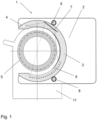
- Fig. 1 shows a schematic representation of a device 1 according to the invention, wherein the device 1 for contactless testing of a butt weld contains a carrier device 2.
- the device 1 shown in Fig. 1 The device 1 shown is purely schematic, which is why the support device 2 is also shown only as a rectangular plate 2.
- the support device 2 can have a different shape as well as further features such as a display or switch.
- a sensor carrier 3 is arranged on the carrier device 2.
- the sensor carrier 3 is arranged in such a way that it can be rotated around the pipes to be welded or the welded pipes or the weld seam, preferably by 360°, thus around the entire pipe. This is done with the Fig.
- the sensor carrier 3 is driven by the two drives 8, which preferably run synchronously, and when the sensor carrier 3 rotates about its central axis or about the pipeline axis, at least one drive 8 is in engagement with the sensor carrier 3, which is why the drives 8 and the sensor carrier 3 preferably have a toothing (not shown), wherein the sensor carrier 3 can also be driven by other types.
- the sensor carrier 3 preferably has a C-shape. This offers the advantage of good rotation and also the possibility that the sensor carrier 3 can be easily moved over the pipe ends to be welded or over the already welded pipes, which Fig. 2 can be seen, and is then arranged concentrically to the pipe 5, whereby the circling of the sensor carrier 3 with the sensor 4 arranged thereon is easily realized in order to enable inspection of the entire weld seam.
- the C-shape is designed in such a way that it is possible to move the sensor carrier 3 around the pipe even with the largest pipe diameter to be inspected on the corresponding device 1.
- An electronic light-sensitive sensor 4 is arranged on the sensor carrier 3.
- Such sensors 4 are known from the prior art as CCD sensors or CMOS sensors. Such sensors 4 are located in digital cameras. Instead of a sensor 4 combined with an optical system, a digital camera containing such a sensor 4 can also be used.
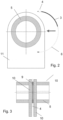
- Fig. 3 The space requirements for the device 1 according to the invention are evident.
- the device 1 according to the invention must be insertable between the pipe clamps 10, which requires a narrow sensor 4, and the support device 2 and the sensor support 3 must be designed very thinly, as they also extend between the pipe clamps 10, and the pipe clamps 10 are moved relatively close together by the welding process.
- the device 1 according to the invention has an illumination 6 so that the weld seam or weld bead recorded by the sensor 4 is clearly visible and the contour is clearly highlighted.
- the lighting 6 is disclosed as backlight 6, wherein in Fig.
- the backlight 6 is designed as a light screen 6. This ensures that all sizes of pipe diameters that can be checked on the device 1 are ideally illuminated by the backlight 6.
- the dashed line represents the theoretical smallest pipe diameter, whereby the center of the pipes 5 was used as the smallest diameter.
- the detection of the weld seam by means of sensor 4 and the corresponding illumination by backlight 6 from a minimum pipe diameter up to a maximum pipe diameter is possible without having to make any changes to the device 1, wherein the sensor 4 or the digital camera 4 and/or the mirror 7 can be arranged movably or movably on the sensor carrier 3 in order to, on the one hand, expand the range of detectable pipe diameters and, on the other hand, to be able to make a fine adjustment for optimal recording. Furthermore, it is advantageous if the device 1 has a mirror 7, since this enlarges the optical path from the sensor 4 to the weld seam, as in Fig. 1 visible.
- Fig. 4 shows the illumination 6 as incident light.
- the incident light illuminates the weld seam at the location of the image, whereby the image of the weld seam by the sensor 4 or the digital camera vertically onto the weld seam or the circumference of the pipes 5.
- This type of recording primarily detects impurities and irritations on the surface and/or identifies the pipe or fitting material.
- Fig. 5 shows the schematic representation when using backlight 6.
- backlight 6 the contour of the weld seam or weld bead is clearly visible.
- the sensor 4 When using backlight 6, the sensor 4 must be directed tangentially to the pipe diameter or the weld seam.
- Backlight 6 radiates in the opposite direction.
- both the backlight and incident light versions can be attached to the sensor carrier 3 to perform the different inspections, and the option of using backlight or incident light individually is also available.
- Fig. 5 The smallest and largest pipe diameters for which the device 1 is applicable are shown.
- the sensor 4 therefore has a correspondingly large viewing angle ⁇ in order to cover the largest possible range of possible pipe diameters that can be tested with the device 1.
- the backlight 6 Since the position of the backlight 6 changes according to the pipe diameter and this is also fixedly arranged on the sensor carrier 3, the backlight 6 is formed by a light screen 6 which extends concentrically to the pipe circumference or along the inner surface of the C-shape of the sensor carrier 3. In Fig. 1 A corresponding light screen 6 is clearly visible. LEDs arranged in a row can be used as possible light sources, although other light sources are also conceivable.
- Fig. 7 The switching on and off of the light screen 6 is shown in sections, whereby the Fig. 7
- the illustrated embodiment of the device according to the invention also has a mirror 7, and the sensor 4 records the weld seam indirectly via the mirror 7.
- the backlight 6 radiates in the opposite direction, with only an illuminated area 12 of the backlight 6 being switched on, thereby avoiding reflection of the illumination vertically to the weld seam and thus preventing interference with the images and making them more clearly recognizable.
- the sensor carrier 3 rotates 360° around the weld seam or the pipe ends while the sensor 4 records the images.
- Fig. 6 represents once again the advantage of a mirror 7.
- the recording by the sensor 4 is carried out tangentially.
- the distance from the sensor 4 to the recording point of the weld seam is relatively large, this increases the perceived width of the backlight 6 and enables the complete coverage of the weld seam width by means of the backlight 6, whereby the contour of the weld seam or weld bead is clearly visible, this is also shown in the illustrations from Fig. 9 clearly visible.
- Fig. 6 the variants of the possible minimum and maximum pipe diameter are shown, although the smallest diameter is only indicated by a dashed tangent to the fictitious smallest diameter, whereby here as well as in Fig. 7 an extension of the detectable area is possible using a movable sensor and/or mirror.
- Fig. 8 depicts the process for arranging the sensor carrier 3 around the pipes and checking them. Initially, the sensor carrier 3 is moved over the pipes 5, which enables the C-shape of the sensor carrier 3. Furthermore, it is shown that the sensor carrier 3, with the sensor 4 arranged thereon, the mirror 7, and the illumination 6, which is designed here as a backlight 6, can be rotated around the pipe 5, preferably by 360°, so that the weld seam or the pipe ends can be completely checked.
Landscapes
- Engineering & Computer Science (AREA)
- Mechanical Engineering (AREA)
- General Physics & Mathematics (AREA)
- Health & Medical Sciences (AREA)
- Physics & Mathematics (AREA)
- Analytical Chemistry (AREA)
- Life Sciences & Earth Sciences (AREA)
- Chemical & Material Sciences (AREA)
- Biochemistry (AREA)
- General Health & Medical Sciences (AREA)
- Immunology (AREA)
- Pathology (AREA)
- Toxicology (AREA)
- Computer Vision & Pattern Recognition (AREA)
- Signal Processing (AREA)
- Investigating Materials By The Use Of Optical Means Adapted For Particular Applications (AREA)
- Length Measuring Devices By Optical Means (AREA)
- Lining Or Joining Of Plastics Or The Like (AREA)
Claims (8)
- Dispositif (1) de vérification sans contact d'une soudure bout à bout de tubes en matière synthétique (5) et de raccords, le dispositif comprenant un dispositif de support (2), un moyen d'éclairage (6) destiné à éclairer le cordon de soudure ou les extrémités de tube pendant la vérification ou la détection au moyen d'un capteur, un support de capteur (3) et au moins un capteur (4) destinés à contrôler les extrémités de tube ou les extrémités de raccord (5) à souder ainsi que le cordon de soudure (9), le capteur (4) étant disposé au niveau du support de capteur (3), le support de capteur (3) étant disposé de manière mobile ou rotative au niveau du dispositif de support (2), le support de capteur (3) étant disposé de telle sorte que le support de capteur (3) puisse tourner autour des tubes à souder ou des tubes soudés ou du cordon de soudure, le capteur (4) étant un capteur photosensible électronique (4), de préférence une caméra numérique (4), le capteur (4) étant dirigé tangentiellement ou de manière indirectement tangentielle à la périphérie de tube ou au cordon de soudure, le moyen d'éclairage (6) étant disposé en contre-jour et conçu sous la forme d'un écran lumineux.
- Dispositif (1) selon la revendication 1, le support de capteur (3) pouvant tourner sur 360° autour des tubes à souder (5) ou du cordon de soudure (9).
- Dispositif (1) selon l'une des revendications 1 ou 2, le support de capteur (3) ayant une forme de C.
- Dispositif (1) selon l'une des revendications précédentes, le moyen d'éclairage (6) étant disposé au niveau du support de capteur (3).
- Dispositif (1) selon l'une des revendications précédentes, le dispositif comprenant un miroir (7), le miroir (7) étant de préférence disposé au niveau du support de capteur (3).
- Dispositif (1) selon l'une des revendications précédentes, le dispositif (1) étant disposé au niveau d'une machine à souder bout à bout (11) ou étant conçu comme un module autonome, le module étant également adaptable à une machine à souder bout à bout (11).
- Procédé de vérification sans contact d'une soudure bout à bout de tubes en matière synthétique et de raccords (5), le procédé comprenant les étapes suivantes :- serrer ou fixer les extrémités de tube à souder (5) avec des côtés frontaux opposés,- aplanir les extrémités de tube,- effectuer de préférence une vérification sans contact des extrémités de tube (5),- souder les extrémités de tube (5) par un procédé de soudage bout à bout connu,- effectuer une vérification sans contact du cordon de soudure (9) pendant le processus de refroidissement,la vérification sans contact étant effectuée à l'aide d'un capteur photosensible électronique (4), de préférence d'une caméra numérique (4), le capteur (4) étant dirigé tangentiellement ou de manière indirectement tangentielle à la périphérie de tube ou au cordon de soudure et étant tourné, de préférence à 360°, autour des extrémités de tuyau (5) ou du cordon de soudure (9) pour effectuer une vérification sans contact.
- Procédé selon la revendication 7, le tube (5) ou le cordon de soudure (9) étant éclairé, de préférence en contre-jour.
Priority Applications (5)
| Application Number | Priority Date | Filing Date | Title |
|---|---|---|---|
| EP14175829.2A EP2963380B2 (fr) | 2014-07-04 | 2014-07-04 | Contrôle sans contact d'une soudure bout à bout |
| KR1020150089512A KR102388638B1 (ko) | 2014-07-04 | 2015-06-24 | 맞대기 용접의 무접촉 검사를 위한 디바이스 및 방법 |
| US14/748,419 US9816943B2 (en) | 2014-07-04 | 2015-06-24 | Contactless examination of a butt weld |
| CN201510387301.9A CN105241375B (zh) | 2014-07-04 | 2015-07-06 | 对接焊接的无接触检查 |
| KR1020220038195A KR20220044465A (ko) | 2014-07-04 | 2022-03-28 | 맞대기 용접의 무접촉 검사 |
Applications Claiming Priority (1)
| Application Number | Priority Date | Filing Date | Title |
|---|---|---|---|
| EP14175829.2A EP2963380B2 (fr) | 2014-07-04 | 2014-07-04 | Contrôle sans contact d'une soudure bout à bout |
Publications (4)
| Publication Number | Publication Date |
|---|---|
| EP2963380A1 EP2963380A1 (fr) | 2016-01-06 |
| EP2963380B1 EP2963380B1 (fr) | 2020-01-08 |
| EP2963380B8 EP2963380B8 (fr) | 2020-02-26 |
| EP2963380B2 true EP2963380B2 (fr) | 2025-06-25 |
Family
ID=51162513
Family Applications (1)
| Application Number | Title | Priority Date | Filing Date |
|---|---|---|---|
| EP14175829.2A Active EP2963380B2 (fr) | 2014-07-04 | 2014-07-04 | Contrôle sans contact d'une soudure bout à bout |
Country Status (4)
| Country | Link |
|---|---|
| US (1) | US9816943B2 (fr) |
| EP (1) | EP2963380B2 (fr) |
| KR (2) | KR102388638B1 (fr) |
| CN (1) | CN105241375B (fr) |
Families Citing this family (19)
| Publication number | Priority date | Publication date | Assignee | Title |
|---|---|---|---|---|
| EP3257656B1 (fr) * | 2016-06-16 | 2018-12-05 | Georg Fischer Rohrleitungssysteme AG | Reconnaissance d'extremite de tuyau |
| DE102016012727A1 (de) * | 2016-10-24 | 2018-04-26 | Blum-Novotest Gmbh | Messsystem zur Messung an Werkzeugen in einer Werkzeugmaschine |
| US10702941B2 (en) | 2017-02-27 | 2020-07-07 | General Electric Technology Gmbh | System, method and apparatus for welding tubes |
| CN107525851B (zh) * | 2017-09-05 | 2020-02-11 | 北京工业大学 | 基于操作手杖的可拆装式纵向模态导波磁致伸缩传感器 |
| EP3550256B1 (fr) | 2018-04-05 | 2021-03-10 | Georg Fischer Rohrleitungssysteme AG | Détection d'une géométrie du cordon de soudure |
| EP3550291A1 (fr) * | 2018-04-05 | 2019-10-09 | Georg Fischer Rohrleitungssysteme AG | Dispositif de fixation pour appareils de mesure sur des tubes |
| US10906080B2 (en) | 2018-04-16 | 2021-02-02 | Ford Motor Company | System and methods to radially orient extruded tubing for vehicle body component |
| CN109501281B (zh) * | 2018-11-23 | 2020-11-17 | 苏州昕源辰机械设备有限公司 | 一种pvc管旋转焊接装置 |
| KR102185790B1 (ko) * | 2019-02-22 | 2020-12-02 | 한양이엔지 주식회사 | 융착 파이프의 융착 비드 검사 장치 |
| FR3095274B1 (fr) * | 2019-04-19 | 2021-04-02 | Framatome Sa | Dispositif de contrôle d’une soudure d’un élément tubulaire longitudinal creux |
| KR102262585B1 (ko) * | 2019-11-12 | 2021-06-08 | 주식회사 명진티에스알 | 용접부의 검사용 캐리어 장치 |
| KR102174209B1 (ko) * | 2019-12-16 | 2020-11-04 | 주식회사 미성 | 복합관의 제조장치 및 그를 이용한 제조방법 |
| KR102594309B1 (ko) * | 2020-04-20 | 2023-10-27 | (주)아그루코리아 | 용접 비드 검사 장치 |
| KR102307971B1 (ko) * | 2020-12-24 | 2021-10-06 | 범아유니텍(주) | 강구 외관 검사장치 |
| FI4194184T3 (fi) * | 2021-12-07 | 2025-09-02 | Fischer G Rohrleitungssysteme Ag | Hitsin arvioiminen hitsausprosessin aikana |
| CN114384070A (zh) * | 2022-01-13 | 2022-04-22 | 江苏核电有限公司 | 用于汽轮发电机低压缸进汽管隔热板的焊缝检查设备 |
| US12434444B2 (en) | 2022-07-04 | 2025-10-07 | Tetra Laval Holdings & Finance S.A. | Method for assessing a sealing of a carton package and an apparatus thereof |
| EP4450262A1 (fr) * | 2023-04-18 | 2024-10-23 | Georg Fischer Rohrleitungssysteme AG | Évaluation de face frontale |
| CN118392888B (zh) * | 2024-04-19 | 2024-10-15 | 北京锐业制药(潜山)有限公司 | 一种粉液双室袋管盖焊接质量检测系统 |
Citations (5)
| Publication number | Priority date | Publication date | Assignee | Title |
|---|---|---|---|---|
| EP0959344A1 (fr) † | 1998-05-20 | 1999-11-24 | COMPRA Gesellschaft für Qualitätssicherung und Umweltschutz mbH | Méthode et assemblage pour la réalisation de tests par irradiation sur des pièces |
| WO2008125102A1 (fr) † | 2007-04-12 | 2008-10-23 | V & M Deutschland Gmbh | Procédé et dispositif destinés à la mesure optique de filets extérieurs |
| WO2011023960A1 (fr) † | 2009-08-28 | 2011-03-03 | Shawcor Ltd. | Procédé et appareil pour l'inspection externe d'une soudure de canalisation |
| WO2013064838A1 (fr) † | 2011-11-02 | 2013-05-10 | Johnson Matthey Public Limited Company | Procédé et appareil de balayage |
| WO2013076541A1 (fr) † | 2011-11-24 | 2013-05-30 | Weldobot Ltd | Système et procédé de soudage portatif et pistage de ligne de soudure modulaires |
Family Cites Families (31)
| Publication number | Priority date | Publication date | Assignee | Title |
|---|---|---|---|---|
| US4160386A (en) * | 1977-06-09 | 1979-07-10 | Southwest Research Institute | Ultrasonic inspection system including apparatus and method for tracking and recording the location of an inspection probe |
| NL7904973A (nl) * | 1979-06-26 | 1980-12-30 | Roentgen Tech Dienst Bv | Stelsel voor het met ultrasone golven onderzoeken van lasverbindingen in pijpen. |
| JPS5841347A (ja) * | 1981-09-04 | 1983-03-10 | Hitachi Ltd | 溶接部検出装置 |
| US4429211A (en) * | 1982-08-02 | 1984-01-31 | United Technologies Corporation | Laser pipe welding system for nonstationary pipe |
| US4734766A (en) * | 1985-08-19 | 1988-03-29 | Kawasaki Steel Corporation | Method and system for locating and inspecting seam weld in metal seam-welded pipe |
| US5263362A (en) * | 1992-06-10 | 1993-11-23 | Fluoroware, Inc. | Weld test tool |
| US5347101A (en) * | 1994-02-07 | 1994-09-13 | Mcdermott International, Inc. | Automatic tracking system for pipeline welding |
| EP0771419A4 (fr) * | 1994-07-18 | 1999-06-23 | Babcock & Wilcox Co | Systeme de transport de capteur pour appareil de soudage en bout par etincelage |
| FR2752180B1 (fr) * | 1996-08-08 | 1999-04-16 | Axal | Procede et dispositif de soudage a pilotage du faisceau de soudage |
| DE19724986C2 (de) * | 1997-06-13 | 1999-07-29 | Jurca Optoelektronik Gmbh | Verfahren zum Verschweißen von Werkstücken und Vorrichtung zu dessen Durchführung |
| US5837966A (en) * | 1997-07-23 | 1998-11-17 | Timmons, Jr.; John E. | Apparatus for weld head to pipe joint alignment for welding |
| IL125200A0 (en) * | 1997-09-01 | 1999-03-12 | Fischer Georg Rohrleitung | An apparatus for butt welding of articles made of thermoplastic material |
| ID20783A (id) * | 1997-09-01 | 1999-03-04 | Fischer Georg Rohrleitung | Metode pengelasan bersama-sama, benda-benda yang terbuat dari bahan plastik |
| JP2000289115A (ja) | 1999-04-06 | 2000-10-17 | Kubota Corp | プラスチック管突合せ融着部の検査方法 |
| KR20010029268A (ko) * | 1999-09-30 | 2001-04-06 | 정주호 | 자동차용 박판의 맞대기 레이저 용접 모니터링 방법 |
| CN2460987Y (zh) * | 2000-09-15 | 2001-11-21 | 清华大学 | 焊缝路径轨迹线实时检测装置 |
| AT413954B (de) * | 2000-11-02 | 2006-07-15 | Fronius Int Gmbh | Erfassungselement für ein schweissgerät |
| JP3424001B2 (ja) * | 2000-12-28 | 2003-07-07 | 川崎重工業株式会社 | レーザ溶接方法およびレーザ溶接装置 |
| WO2002059566A2 (fr) * | 2001-01-09 | 2002-08-01 | Edison Welding Institute | Procede d'inspection de soudure bout a bout non destructif |
| FR2840991B1 (fr) * | 2002-06-17 | 2005-05-06 | Air Liquide | Procede de controle par ultrasons de joints soudes |
| WO2004007139A1 (fr) * | 2002-07-17 | 2004-01-22 | Shell Internationale Research Maatschappij B.V. | Procede de soudage par forgeage |
| DE10311247B8 (de) * | 2003-03-14 | 2008-05-08 | Inos Automationssoftware Gmbh | Portable Einrichtung zum Erfassen einer Lage und von Abmessungen eines Objekts |
| EP1691949B1 (fr) * | 2003-12-10 | 2011-02-23 | VIETZ GmbH | Dispositif de soudage orbital pour construction de tuyauteries |
| CN1289252C (zh) * | 2004-10-21 | 2006-12-13 | 上海交通大学 | 焊缝自主跟踪方法 |
| KR100797239B1 (ko) * | 2005-12-23 | 2008-01-23 | 주식회사 포스코 | 강판의 용접부 온라인 검출장치 및 방법 |
| US8104347B2 (en) * | 2008-07-16 | 2012-01-31 | Röntgen Technische Dienst B.V. | Ultrasonic inspection method and device for plastics walls |
| US8552337B2 (en) * | 2009-06-11 | 2013-10-08 | Illinois Tool Works Inc. | Weld defect detection systems and methods for laser hybrid welding |
| US8739574B2 (en) * | 2011-09-21 | 2014-06-03 | Polaronyx, Inc. | Method and apparatus for three dimensional large area welding and sealing of optically transparent materials |
| DE102012007563B3 (de) | 2012-04-10 | 2013-05-29 | Salzgitter Mannesmann Line Pipe Gmbh | Vorrichtung zum Verbinden der Enden von Rohren aus Stahl mittels Orbitalschweißen |
| PT2908978T (pt) * | 2012-10-19 | 2022-03-30 | Ipg Photonics Corp | Dispositivo passo a passo para soldadura a laser robotizado |
| DE202014100284U1 (de) | 2014-01-23 | 2014-02-18 | Illinois Tool Works Inc. | Vorrichtung zum Ausrichten und Verschweissen von Gegenständen |
-
2014
- 2014-07-04 EP EP14175829.2A patent/EP2963380B2/fr active Active
-
2015
- 2015-06-24 US US14/748,419 patent/US9816943B2/en active Active
- 2015-06-24 KR KR1020150089512A patent/KR102388638B1/ko active Active
- 2015-07-06 CN CN201510387301.9A patent/CN105241375B/zh active Active
-
2022
- 2022-03-28 KR KR1020220038195A patent/KR20220044465A/ko not_active Ceased
Patent Citations (5)
| Publication number | Priority date | Publication date | Assignee | Title |
|---|---|---|---|---|
| EP0959344A1 (fr) † | 1998-05-20 | 1999-11-24 | COMPRA Gesellschaft für Qualitätssicherung und Umweltschutz mbH | Méthode et assemblage pour la réalisation de tests par irradiation sur des pièces |
| WO2008125102A1 (fr) † | 2007-04-12 | 2008-10-23 | V & M Deutschland Gmbh | Procédé et dispositif destinés à la mesure optique de filets extérieurs |
| WO2011023960A1 (fr) † | 2009-08-28 | 2011-03-03 | Shawcor Ltd. | Procédé et appareil pour l'inspection externe d'une soudure de canalisation |
| WO2013064838A1 (fr) † | 2011-11-02 | 2013-05-10 | Johnson Matthey Public Limited Company | Procédé et appareil de balayage |
| WO2013076541A1 (fr) † | 2011-11-24 | 2013-05-30 | Weldobot Ltd | Système et procédé de soudage portatif et pistage de ligne de soudure modulaires |
Non-Patent Citations (2)
| Title |
|---|
| ANDREA SPITZER: "Verwendung von Spiegeln zur vollständigen photogrammetrischen Oberflächenrekonstruktion von schwer zugänglichen Objekten", DIPLOMARBEIT, September 2009 (2009-09-01), pages ii-iv, 1 - 62, XP055742867, Retrieved from the Internet <URL:https://publik.tuwien.ac.at/files/PubDat_178059.pdf> † |
| ANONYMOUS: "DVS 2207 Teil 1 - Schweißen von thermoplastischen Kunststoffen Heizelementschweißen von Rohren, Rohrleitungsteilen und Tafeln aus PE-HD", DVS RICHTLINIE, August 1995 (1995-08-01), pages 184 - 195, XP055742860 † |
Also Published As
| Publication number | Publication date |
|---|---|
| KR20220044465A (ko) | 2022-04-08 |
| CN105241375B (zh) | 2020-02-14 |
| EP2963380B8 (fr) | 2020-02-26 |
| CN105241375A (zh) | 2016-01-13 |
| US9816943B2 (en) | 2017-11-14 |
| KR102388638B1 (ko) | 2022-04-19 |
| EP2963380B1 (fr) | 2020-01-08 |
| KR102388638B9 (ko) | 2023-08-04 |
| EP2963380A1 (fr) | 2016-01-06 |
| KR20160004919A (ko) | 2016-01-13 |
| US20160003751A1 (en) | 2016-01-07 |
Similar Documents
| Publication | Publication Date | Title |
|---|---|---|
| EP2963380B2 (fr) | Contrôle sans contact d'une soudure bout à bout | |
| EP2598861B1 (fr) | Dispositif d'inspection, installation de fabrication équipée d'un dispositif d'inspection et procédé d'inspection de récipients | |
| EP0228500B1 (fr) | Méthode et dispositif pour la mesure sans contact du profil d'une roue des roues d'ensembles de roues de voie ferrée | |
| DE102007017747B4 (de) | Verfahren und Vorrichtung zur optischen Vermessung von Außengewinden | |
| EP3550256B1 (fr) | Détection d'une géométrie du cordon de soudure | |
| EP2439490B2 (fr) | Dispositif et procédé de reconnaissance d'une position de rotation de préformes en plastique | |
| EP3204759B1 (fr) | Dispositif d'inspection et procédé d'inspection en lumière transmise de récipients | |
| EP2205933B1 (fr) | Dispositif de mesure et/ou de contrôle optique de produits oblongs | |
| DE102009019459A1 (de) | Vorrichtung zur Abbildung der Innenfläche eines Hohlraumes in einem Werkstück | |
| EP3140644A1 (fr) | Thermographie pour l'assurance qualité dans un procédé de fabrication génératif | |
| EP3199943A1 (fr) | Dispositif et procédé de détection d'au moins une surface en partie réfléchissante | |
| DE102013108722B4 (de) | Verfahren und Vorrichtung zum Erfassen von Defekten einer ebenen Oberfläche | |
| DE19910699A1 (de) | Vorrichtung zum Messen der Breite eines Spalts | |
| DE102012010190B4 (de) | Verfahren, Vorrichtung und Endoskop sowieAufsatz | |
| DE102007007192A1 (de) | Messanordnung und Verfahren zum Erfassen der Oberfläche von Objekten | |
| WO2020008077A1 (fr) | Procédé et dispositif de contrôle optique de préformes | |
| EP1901030A2 (fr) | Agencement de mesure et procédé de détection de la surface d'objets | |
| EP3510877B1 (fr) | Dispositif et procédé de vérification des articles en forme de boudin de l'industrie de traitement du tabac | |
| EP0987541B1 (fr) | Dispositif de contrôle optique de qualité de la surface interne d'un tube | |
| DE102011007751B4 (de) | Weitfeldmikroskop und Verfahren zur Weitfeldmikroskopie | |
| AT520351B1 (de) | Freiformflächeninspektion mit schaltbarer Lichtquelle | |
| DE102009009393A1 (de) | Vorrichtung und Verfahren zum Vermessen eines Körpers | |
| EP1475628A2 (fr) | Dispositif d'éclairage | |
| DE102015207175A1 (de) | Vorrichtung zum Überprüfen eines Verschlussbereichs eines verschlossenen Behältnisses | |
| DE102024116295A1 (de) | Verfahren zur Materialprüfung bei einem Objekt in einer Produktions- und/oder Förderlinie und Inspektionsvorrichtung |
Legal Events
| Date | Code | Title | Description |
|---|---|---|---|
| PUAI | Public reference made under article 153(3) epc to a published international application that has entered the european phase |
Free format text: ORIGINAL CODE: 0009012 |
|
| AK | Designated contracting states |
Kind code of ref document: A1 Designated state(s): AL AT BE BG CH CY CZ DE DK EE ES FI FR GB GR HR HU IE IS IT LI LT LU LV MC MK MT NL NO PL PT RO RS SE SI SK SM TR |
|
| AX | Request for extension of the european patent |
Extension state: BA ME |
|
| 17P | Request for examination filed |
Effective date: 20160628 |
|
| RBV | Designated contracting states (corrected) |
Designated state(s): AL AT BE BG CH CY CZ DE DK EE ES FI FR GB GR HR HU IE IS IT LI LT LU LV MC MK MT NL NO PL PT RO RS SE SI SK SM TR |
|
| STAA | Information on the status of an ep patent application or granted ep patent |
Free format text: STATUS: EXAMINATION IS IN PROGRESS |
|
| 17Q | First examination report despatched |
Effective date: 20170519 |
|
| REG | Reference to a national code |
Ref country code: DE Ref legal event code: R079 Ref document number: 502014013416 Country of ref document: DE Free format text: PREVIOUS MAIN CLASS: G01B0011240000 Ipc: G01N0021952000 |
|
| GRAP | Despatch of communication of intention to grant a patent |
Free format text: ORIGINAL CODE: EPIDOSNIGR1 |
|
| STAA | Information on the status of an ep patent application or granted ep patent |
Free format text: STATUS: GRANT OF PATENT IS INTENDED |
|
| RIC1 | Information provided on ipc code assigned before grant |
Ipc: G01N 21/952 20060101AFI20190802BHEP Ipc: G01B 11/24 20060101ALI20190802BHEP Ipc: B29C 65/02 20060101ALI20190802BHEP Ipc: B29C 65/00 20060101ALI20190802BHEP Ipc: B29C 65/82 20060101ALI20190802BHEP |
|
| INTG | Intention to grant announced |
Effective date: 20190827 |
|
| RIN1 | Information on inventor provided before grant (corrected) |
Inventor name: REIZ, ROBERT |
|
| RIN1 | Information on inventor provided before grant (corrected) |
Inventor name: REIZ, ROBERT |
|
| GRAS | Grant fee paid |
Free format text: ORIGINAL CODE: EPIDOSNIGR3 |
|
| GRAA | (expected) grant |
Free format text: ORIGINAL CODE: 0009210 |
|
| STAA | Information on the status of an ep patent application or granted ep patent |
Free format text: STATUS: THE PATENT HAS BEEN GRANTED |
|
| AK | Designated contracting states |
Kind code of ref document: B1 Designated state(s): AL AT BE BG CH CY CZ DE DK EE ES FI FR GB GR HR HU IE IS IT LI LT LU LV MC MK MT NL NO PL PT RO RS SE SI SK SM TR |
|
| REG | Reference to a national code |
Ref country code: GB Ref legal event code: FG4D Free format text: NOT ENGLISH |
|
| REG | Reference to a national code |
Ref country code: CH Ref legal event code: EP Ref country code: CH Ref legal event code: NV Representative=s name: GEORG FISCHER AG, CH |
|
| RIN2 | Information on inventor provided after grant (corrected) |
Inventor name: REIZ, ROBERT Inventor name: MARTY, FLORENTIN Inventor name: BROSSI, STEVEN |
|
| REG | Reference to a national code |
Ref country code: DE Ref legal event code: R096 Ref document number: 502014013416 Country of ref document: DE |
|
| REG | Reference to a national code |
Ref country code: CH Ref legal event code: PK Free format text: BERICHTIGUNG B8 |
|
| REG | Reference to a national code |
Ref country code: IE Ref legal event code: FG4D Free format text: LANGUAGE OF EP DOCUMENT: GERMAN |
|
| REG | Reference to a national code |
Ref country code: AT Ref legal event code: REF Ref document number: 1223315 Country of ref document: AT Kind code of ref document: T Effective date: 20200215 |
|
| REG | Reference to a national code |
Ref country code: SE Ref legal event code: TRGR |
|
| REG | Reference to a national code |
Ref country code: NL Ref legal event code: MP Effective date: 20200108 |
|
| REG | Reference to a national code |
Ref country code: LT Ref legal event code: MG4D |
|
| PG25 | Lapsed in a contracting state [announced via postgrant information from national office to epo] |
Ref country code: RS Free format text: LAPSE BECAUSE OF FAILURE TO SUBMIT A TRANSLATION OF THE DESCRIPTION OR TO PAY THE FEE WITHIN THE PRESCRIBED TIME-LIMIT Effective date: 20200108 Ref country code: NO Free format text: LAPSE BECAUSE OF FAILURE TO SUBMIT A TRANSLATION OF THE DESCRIPTION OR TO PAY THE FEE WITHIN THE PRESCRIBED TIME-LIMIT Effective date: 20200408 Ref country code: PT Free format text: LAPSE BECAUSE OF FAILURE TO SUBMIT A TRANSLATION OF THE DESCRIPTION OR TO PAY THE FEE WITHIN THE PRESCRIBED TIME-LIMIT Effective date: 20200531 Ref country code: FI Free format text: LAPSE BECAUSE OF FAILURE TO SUBMIT A TRANSLATION OF THE DESCRIPTION OR TO PAY THE FEE WITHIN THE PRESCRIBED TIME-LIMIT Effective date: 20200108 Ref country code: NL Free format text: LAPSE BECAUSE OF FAILURE TO SUBMIT A TRANSLATION OF THE DESCRIPTION OR TO PAY THE FEE WITHIN THE PRESCRIBED TIME-LIMIT Effective date: 20200108 Ref country code: LT Free format text: LAPSE BECAUSE OF FAILURE TO SUBMIT A TRANSLATION OF THE DESCRIPTION OR TO PAY THE FEE WITHIN THE PRESCRIBED TIME-LIMIT Effective date: 20200108 |
|
| PG25 | Lapsed in a contracting state [announced via postgrant information from national office to epo] |
Ref country code: LV Free format text: LAPSE BECAUSE OF FAILURE TO SUBMIT A TRANSLATION OF THE DESCRIPTION OR TO PAY THE FEE WITHIN THE PRESCRIBED TIME-LIMIT Effective date: 20200108 Ref country code: HR Free format text: LAPSE BECAUSE OF FAILURE TO SUBMIT A TRANSLATION OF THE DESCRIPTION OR TO PAY THE FEE WITHIN THE PRESCRIBED TIME-LIMIT Effective date: 20200108 Ref country code: BG Free format text: LAPSE BECAUSE OF FAILURE TO SUBMIT A TRANSLATION OF THE DESCRIPTION OR TO PAY THE FEE WITHIN THE PRESCRIBED TIME-LIMIT Effective date: 20200408 Ref country code: IS Free format text: LAPSE BECAUSE OF FAILURE TO SUBMIT A TRANSLATION OF THE DESCRIPTION OR TO PAY THE FEE WITHIN THE PRESCRIBED TIME-LIMIT Effective date: 20200508 Ref country code: GR Free format text: LAPSE BECAUSE OF FAILURE TO SUBMIT A TRANSLATION OF THE DESCRIPTION OR TO PAY THE FEE WITHIN THE PRESCRIBED TIME-LIMIT Effective date: 20200409 |
|
| REG | Reference to a national code |
Ref country code: DE Ref legal event code: R026 Ref document number: 502014013416 Country of ref document: DE |
|
| PLBI | Opposition filed |
Free format text: ORIGINAL CODE: 0009260 |
|
| PLAX | Notice of opposition and request to file observation + time limit sent |
Free format text: ORIGINAL CODE: EPIDOSNOBS2 |
|
| PG25 | Lapsed in a contracting state [announced via postgrant information from national office to epo] |
Ref country code: SK Free format text: LAPSE BECAUSE OF FAILURE TO SUBMIT A TRANSLATION OF THE DESCRIPTION OR TO PAY THE FEE WITHIN THE PRESCRIBED TIME-LIMIT Effective date: 20200108 Ref country code: RO Free format text: LAPSE BECAUSE OF FAILURE TO SUBMIT A TRANSLATION OF THE DESCRIPTION OR TO PAY THE FEE WITHIN THE PRESCRIBED TIME-LIMIT Effective date: 20200108 Ref country code: CZ Free format text: LAPSE BECAUSE OF FAILURE TO SUBMIT A TRANSLATION OF THE DESCRIPTION OR TO PAY THE FEE WITHIN THE PRESCRIBED TIME-LIMIT Effective date: 20200108 Ref country code: ES Free format text: LAPSE BECAUSE OF FAILURE TO SUBMIT A TRANSLATION OF THE DESCRIPTION OR TO PAY THE FEE WITHIN THE PRESCRIBED TIME-LIMIT Effective date: 20200108 Ref country code: DK Free format text: LAPSE BECAUSE OF FAILURE TO SUBMIT A TRANSLATION OF THE DESCRIPTION OR TO PAY THE FEE WITHIN THE PRESCRIBED TIME-LIMIT Effective date: 20200108 Ref country code: SM Free format text: LAPSE BECAUSE OF FAILURE TO SUBMIT A TRANSLATION OF THE DESCRIPTION OR TO PAY THE FEE WITHIN THE PRESCRIBED TIME-LIMIT Effective date: 20200108 Ref country code: EE Free format text: LAPSE BECAUSE OF FAILURE TO SUBMIT A TRANSLATION OF THE DESCRIPTION OR TO PAY THE FEE WITHIN THE PRESCRIBED TIME-LIMIT Effective date: 20200108 |
|
| PGFP | Annual fee paid to national office [announced via postgrant information from national office to epo] |
Ref country code: FR Payment date: 20200723 Year of fee payment: 7 Ref country code: IE Payment date: 20200727 Year of fee payment: 7 Ref country code: GB Payment date: 20200727 Year of fee payment: 7 |
|
| 26 | Opposition filed |
Opponent name: AGRU KUNSTSTOFFTECHNIK GESELLSCHAFT M.B.H. Effective date: 20201006 |
|
| PGFP | Annual fee paid to national office [announced via postgrant information from national office to epo] |
Ref country code: SE Payment date: 20200727 Year of fee payment: 7 |
|
| PLBB | Reply of patent proprietor to notice(s) of opposition received |
Free format text: ORIGINAL CODE: EPIDOSNOBS3 |
|
| PG25 | Lapsed in a contracting state [announced via postgrant information from national office to epo] |
Ref country code: MC Free format text: LAPSE BECAUSE OF FAILURE TO SUBMIT A TRANSLATION OF THE DESCRIPTION OR TO PAY THE FEE WITHIN THE PRESCRIBED TIME-LIMIT Effective date: 20200108 Ref country code: PL Free format text: LAPSE BECAUSE OF FAILURE TO SUBMIT A TRANSLATION OF THE DESCRIPTION OR TO PAY THE FEE WITHIN THE PRESCRIBED TIME-LIMIT Effective date: 20200108 Ref country code: SI Free format text: LAPSE BECAUSE OF FAILURE TO SUBMIT A TRANSLATION OF THE DESCRIPTION OR TO PAY THE FEE WITHIN THE PRESCRIBED TIME-LIMIT Effective date: 20200108 |
|
| REG | Reference to a national code |
Ref country code: BE Ref legal event code: MM Effective date: 20200731 |
|
| PG25 | Lapsed in a contracting state [announced via postgrant information from national office to epo] |
Ref country code: LU Free format text: LAPSE BECAUSE OF NON-PAYMENT OF DUE FEES Effective date: 20200704 |
|
| PG25 | Lapsed in a contracting state [announced via postgrant information from national office to epo] |
Ref country code: BE Free format text: LAPSE BECAUSE OF NON-PAYMENT OF DUE FEES Effective date: 20200731 |
|
| PLAB | Opposition data, opponent's data or that of the opponent's representative modified |
Free format text: ORIGINAL CODE: 0009299OPPO |
|
| R26 | Opposition filed (corrected) |
Opponent name: AGRU KUNSTSTOFFTECHNIK GESELLSCHAFT M.B.H. Effective date: 20201006 |
|
| GBPC | Gb: european patent ceased through non-payment of renewal fee |
Effective date: 20210704 |
|
| PG25 | Lapsed in a contracting state [announced via postgrant information from national office to epo] |
Ref country code: GB Free format text: LAPSE BECAUSE OF NON-PAYMENT OF DUE FEES Effective date: 20210704 |
|
| PG25 | Lapsed in a contracting state [announced via postgrant information from national office to epo] |
Ref country code: TR Free format text: LAPSE BECAUSE OF FAILURE TO SUBMIT A TRANSLATION OF THE DESCRIPTION OR TO PAY THE FEE WITHIN THE PRESCRIBED TIME-LIMIT Effective date: 20200108 Ref country code: SE Free format text: LAPSE BECAUSE OF NON-PAYMENT OF DUE FEES Effective date: 20210705 Ref country code: MT Free format text: LAPSE BECAUSE OF FAILURE TO SUBMIT A TRANSLATION OF THE DESCRIPTION OR TO PAY THE FEE WITHIN THE PRESCRIBED TIME-LIMIT Effective date: 20200108 Ref country code: FR Free format text: LAPSE BECAUSE OF NON-PAYMENT OF DUE FEES Effective date: 20210731 Ref country code: CY Free format text: LAPSE BECAUSE OF FAILURE TO SUBMIT A TRANSLATION OF THE DESCRIPTION OR TO PAY THE FEE WITHIN THE PRESCRIBED TIME-LIMIT Effective date: 20200108 |
|
| PG25 | Lapsed in a contracting state [announced via postgrant information from national office to epo] |
Ref country code: MK Free format text: LAPSE BECAUSE OF FAILURE TO SUBMIT A TRANSLATION OF THE DESCRIPTION OR TO PAY THE FEE WITHIN THE PRESCRIBED TIME-LIMIT Effective date: 20200108 Ref country code: AL Free format text: LAPSE BECAUSE OF FAILURE TO SUBMIT A TRANSLATION OF THE DESCRIPTION OR TO PAY THE FEE WITHIN THE PRESCRIBED TIME-LIMIT Effective date: 20200108 |
|
| PG25 | Lapsed in a contracting state [announced via postgrant information from national office to epo] |
Ref country code: IE Free format text: LAPSE BECAUSE OF NON-PAYMENT OF DUE FEES Effective date: 20210704 |
|
| APAH | Appeal reference modified |
Free format text: ORIGINAL CODE: EPIDOSCREFNO |
|
| APBM | Appeal reference recorded |
Free format text: ORIGINAL CODE: EPIDOSNREFNO |
|
| APBP | Date of receipt of notice of appeal recorded |
Free format text: ORIGINAL CODE: EPIDOSNNOA2O |
|
| APAW | Appeal reference deleted |
Free format text: ORIGINAL CODE: EPIDOSDREFNO |
|
| APBQ | Date of receipt of statement of grounds of appeal recorded |
Free format text: ORIGINAL CODE: EPIDOSNNOA3O |
|
| APBQ | Date of receipt of statement of grounds of appeal recorded |
Free format text: ORIGINAL CODE: EPIDOSNNOA3O |
|
| P01 | Opt-out of the competence of the unified patent court (upc) registered |
Effective date: 20230526 |
|
| APBU | Appeal procedure closed |
Free format text: ORIGINAL CODE: EPIDOSNNOA9O |
|
| PUAH | Patent maintained in amended form |
Free format text: ORIGINAL CODE: 0009272 |
|
| STAA | Information on the status of an ep patent application or granted ep patent |
Free format text: STATUS: PATENT MAINTAINED AS AMENDED |
|
| 27A | Patent maintained in amended form |
Effective date: 20250625 |
|
| AK | Designated contracting states |
Kind code of ref document: B2 Designated state(s): AL AT BE BG CH CY CZ DE DK EE ES FI FR GB GR HR HU IE IS IT LI LT LU LV MC MK MT NL NO PL PT RO RS SE SI SK SM TR |
|
| REG | Reference to a national code |
Ref country code: DE Ref legal event code: R102 Ref document number: 502014013416 Country of ref document: DE |
|
| PGFP | Annual fee paid to national office [announced via postgrant information from national office to epo] |
Ref country code: DE Payment date: 20250722 Year of fee payment: 12 |
|
| PGFP | Annual fee paid to national office [announced via postgrant information from national office to epo] |
Ref country code: IT Payment date: 20250724 Year of fee payment: 12 |
|
| PGFP | Annual fee paid to national office [announced via postgrant information from national office to epo] |
Ref country code: AT Payment date: 20250722 Year of fee payment: 12 |
|
| PGFP | Annual fee paid to national office [announced via postgrant information from national office to epo] |
Ref country code: CH Payment date: 20250801 Year of fee payment: 12 |