EP2963380B1 - Berührungsloses Überprüfen einer Stumpfschweissung - Google Patents
Berührungsloses Überprüfen einer Stumpfschweissung Download PDFInfo
- Publication number
- EP2963380B1 EP2963380B1 EP14175829.2A EP14175829A EP2963380B1 EP 2963380 B1 EP2963380 B1 EP 2963380B1 EP 14175829 A EP14175829 A EP 14175829A EP 2963380 B1 EP2963380 B1 EP 2963380B1
- Authority
- EP
- European Patent Office
- Prior art keywords
- sensor
- weld seam
- pipe
- pipe ends
- welded
- Prior art date
- Legal status (The legal status is an assumption and is not a legal conclusion. Google has not performed a legal analysis and makes no representation as to the accuracy of the status listed.)
- Active
Links
Images

Classifications
-
- G—PHYSICS
- G01—MEASURING; TESTING
- G01N—INVESTIGATING OR ANALYSING MATERIALS BY DETERMINING THEIR CHEMICAL OR PHYSICAL PROPERTIES
- G01N21/00—Investigating or analysing materials by the use of optical means, i.e. using sub-millimetre waves, infrared, visible or ultraviolet light
- G01N21/84—Systems specially adapted for particular applications
- G01N21/88—Investigating the presence of flaws or contamination
- G01N21/95—Investigating the presence of flaws or contamination characterised by the material or shape of the object to be examined
- G01N21/952—Inspecting the exterior surface of cylindrical bodies or wires
-
- B—PERFORMING OPERATIONS; TRANSPORTING
- B29—WORKING OF PLASTICS; WORKING OF SUBSTANCES IN A PLASTIC STATE IN GENERAL
- B29C—SHAPING OR JOINING OF PLASTICS; SHAPING OF MATERIAL IN A PLASTIC STATE, NOT OTHERWISE PROVIDED FOR; AFTER-TREATMENT OF THE SHAPED PRODUCTS, e.g. REPAIRING
- B29C65/00—Joining or sealing of preformed parts, e.g. welding of plastics materials; Apparatus therefor
- B29C65/02—Joining or sealing of preformed parts, e.g. welding of plastics materials; Apparatus therefor by heating, with or without pressure
-
- B—PERFORMING OPERATIONS; TRANSPORTING
- B29—WORKING OF PLASTICS; WORKING OF SUBSTANCES IN A PLASTIC STATE IN GENERAL
- B29C—SHAPING OR JOINING OF PLASTICS; SHAPING OF MATERIAL IN A PLASTIC STATE, NOT OTHERWISE PROVIDED FOR; AFTER-TREATMENT OF THE SHAPED PRODUCTS, e.g. REPAIRING
- B29C65/00—Joining or sealing of preformed parts, e.g. welding of plastics materials; Apparatus therefor
- B29C65/78—Means for handling the parts to be joined, e.g. for making containers or hollow articles, e.g. means for handling sheets, plates, web-like materials, tubular articles, hollow articles or elements to be joined therewith; Means for discharging the joined articles from the joining apparatus
- B29C65/7841—Holding or clamping means for handling purposes
-
- B—PERFORMING OPERATIONS; TRANSPORTING
- B29—WORKING OF PLASTICS; WORKING OF SUBSTANCES IN A PLASTIC STATE IN GENERAL
- B29C—SHAPING OR JOINING OF PLASTICS; SHAPING OF MATERIAL IN A PLASTIC STATE, NOT OTHERWISE PROVIDED FOR; AFTER-TREATMENT OF THE SHAPED PRODUCTS, e.g. REPAIRING
- B29C65/00—Joining or sealing of preformed parts, e.g. welding of plastics materials; Apparatus therefor
- B29C65/82—Testing the joint
- B29C65/8253—Testing the joint by the use of waves or particle radiation, e.g. visual examination, scanning electron microscopy, or X-rays
-
- B—PERFORMING OPERATIONS; TRANSPORTING
- B29—WORKING OF PLASTICS; WORKING OF SUBSTANCES IN A PLASTIC STATE IN GENERAL
- B29C—SHAPING OR JOINING OF PLASTICS; SHAPING OF MATERIAL IN A PLASTIC STATE, NOT OTHERWISE PROVIDED FOR; AFTER-TREATMENT OF THE SHAPED PRODUCTS, e.g. REPAIRING
- B29C66/00—General aspects of processes or apparatus for joining preformed parts
- B29C66/01—General aspects dealing with the joint area or with the area to be joined
- B29C66/02—Preparation of the material, in the area to be joined, prior to joining or welding
- B29C66/022—Mechanical pre-treatments, e.g. reshaping
- B29C66/0224—Mechanical pre-treatments, e.g. reshaping with removal of material
- B29C66/02245—Abrading, e.g. grinding, sanding, sandblasting or scraping
-
- B—PERFORMING OPERATIONS; TRANSPORTING
- B29—WORKING OF PLASTICS; WORKING OF SUBSTANCES IN A PLASTIC STATE IN GENERAL
- B29C—SHAPING OR JOINING OF PLASTICS; SHAPING OF MATERIAL IN A PLASTIC STATE, NOT OTHERWISE PROVIDED FOR; AFTER-TREATMENT OF THE SHAPED PRODUCTS, e.g. REPAIRING
- B29C66/00—General aspects of processes or apparatus for joining preformed parts
- B29C66/01—General aspects dealing with the joint area or with the area to be joined
- B29C66/05—Particular design of joint configurations
- B29C66/10—Particular design of joint configurations particular design of the joint cross-sections
- B29C66/11—Joint cross-sections comprising a single joint-segment, i.e. one of the parts to be joined comprising a single joint-segment in the joint cross-section
- B29C66/114—Single butt joints
- B29C66/1142—Single butt to butt joints
-
- B—PERFORMING OPERATIONS; TRANSPORTING
- B29—WORKING OF PLASTICS; WORKING OF SUBSTANCES IN A PLASTIC STATE IN GENERAL
- B29C—SHAPING OR JOINING OF PLASTICS; SHAPING OF MATERIAL IN A PLASTIC STATE, NOT OTHERWISE PROVIDED FOR; AFTER-TREATMENT OF THE SHAPED PRODUCTS, e.g. REPAIRING
- B29C66/00—General aspects of processes or apparatus for joining preformed parts
- B29C66/50—General aspects of joining tubular articles; General aspects of joining long products, i.e. bars or profiled elements; General aspects of joining single elements to tubular articles, hollow articles or bars; General aspects of joining several hollow-preforms to form hollow or tubular articles
- B29C66/51—Joining tubular articles, profiled elements or bars; Joining single elements to tubular articles, hollow articles or bars; Joining several hollow-preforms to form hollow or tubular articles
- B29C66/52—Joining tubular articles, bars or profiled elements
- B29C66/522—Joining tubular articles
- B29C66/5221—Joining tubular articles for forming coaxial connections, i.e. the tubular articles to be joined forming a zero angle relative to each other
-
- B—PERFORMING OPERATIONS; TRANSPORTING
- B29—WORKING OF PLASTICS; WORKING OF SUBSTANCES IN A PLASTIC STATE IN GENERAL
- B29C—SHAPING OR JOINING OF PLASTICS; SHAPING OF MATERIAL IN A PLASTIC STATE, NOT OTHERWISE PROVIDED FOR; AFTER-TREATMENT OF THE SHAPED PRODUCTS, e.g. REPAIRING
- B29C66/00—General aspects of processes or apparatus for joining preformed parts
- B29C66/90—Measuring or controlling the joining process
- B29C66/97—Checking completion of joining or correct joining by using indications on at least one of the joined parts
- B29C66/974—Checking completion of joining or correct joining by using indications on at least one of the joined parts by checking the bead or burr form
-
- B—PERFORMING OPERATIONS; TRANSPORTING
- B29—WORKING OF PLASTICS; WORKING OF SUBSTANCES IN A PLASTIC STATE IN GENERAL
- B29D—PRODUCING PARTICULAR ARTICLES FROM PLASTICS OR FROM SUBSTANCES IN A PLASTIC STATE
- B29D23/00—Producing tubular articles
- B29D23/001—Pipes; Pipe joints
-
- G—PHYSICS
- G01—MEASURING; TESTING
- G01B—MEASURING LENGTH, THICKNESS OR SIMILAR LINEAR DIMENSIONS; MEASURING ANGLES; MEASURING AREAS; MEASURING IRREGULARITIES OF SURFACES OR CONTOURS
- G01B11/00—Measuring arrangements characterised by the use of optical techniques
- G01B11/24—Measuring arrangements characterised by the use of optical techniques for measuring contours or curvatures
-
- G—PHYSICS
- G01—MEASURING; TESTING
- G01N—INVESTIGATING OR ANALYSING MATERIALS BY DETERMINING THEIR CHEMICAL OR PHYSICAL PROPERTIES
- G01N21/00—Investigating or analysing materials by the use of optical means, i.e. using sub-millimetre waves, infrared, visible or ultraviolet light
- G01N21/84—Systems specially adapted for particular applications
- G01N21/88—Investigating the presence of flaws or contamination
- G01N21/8851—Scan or image signal processing specially adapted therefor, e.g. for scan signal adjustment, for detecting different kinds of defects, for compensating for structures, markings, edges
-
- G—PHYSICS
- G01—MEASURING; TESTING
- G01N—INVESTIGATING OR ANALYSING MATERIALS BY DETERMINING THEIR CHEMICAL OR PHYSICAL PROPERTIES
- G01N2201/00—Features of devices classified in G01N21/00
- G01N2201/06—Illumination; Optics
- G01N2201/062—LED's
Definitions
- the invention relates to a device and a method for the contactless inspection of a butt welding of plastic pipes and fittings, the device having a carrier device, lighting and at least one sensor, the pipe ends being welded by means of a known butt welding method and a contactless inspection of the weld seam and optional testing of the Pipe ends or fitting ends before welding is carried out by means of a sensor.
- the JP 2000289115A discloses an inspection of a welding of plastic pipes by means of an ultrasonic sensor, whereby a statement regarding the fusion of the pipe wall inside, which is not visible, can also be obtained.
- US 2002/084260 A1 . US 2004/179206 A1 . DE 10 2012 007563 B3 . DE 20 2014 100284 U1 . US 2007/119829 A1 . WO 2014/063153 A1 . US 2010/314362 A1 and US 6 084 203 A disclose devices for contactless inspection of welds. It is the object of the invention to propose a device and a method associated therewith which enable a non-destructive or contactless, constant quality check of the weld in butt-welded plastic pipes without an economic disadvantage resulting from a higher expenditure of time.
- the device according to the invention contains a carrier device, this being designed and designed according to the application of the device or its area of application, whereby the device according to the invention can be manufactured as an autonomous test device or can also be designed as a retrofittable module for an existing butt welding machine.
- the device according to the invention can also be designed such that it is already firmly integrated in a butt welding machine.
- an operating unit must also be provided or can be dispensed with, since the operating unit of the welding machine can possibly be used.
- the device has an illumination in order to illuminate the weld seam or the pipe ends by means of a sensor during the check or the recordings, so that the contours of the weld seam or weld bead as well as the pipe ends can be clearly recognized before the welding process.
- the sensor or the digital camera takes pictures of the welding or the Weld seam and before welding the pipe ends to be welded.
- a digital camera can also be used, since these usually contain such a sensor.
- the digital cameras known from the prior art are so small that they can be used without problems for the present invention.
- the recordings of the weld seam or the pipe ends can take place as a film or continuously, or individual image recordings can also be made, the individual image recordings made during a check of a weld seam can be selected individually.
- the sensor or the digital camera is movably or movably arranged on the sensor carrier or can be aligned accordingly if necessary.
- the device according to the invention has a sensor carrier.
- the sensor is preferably arranged on the sensor carrier and the sensor carrier in turn on the carrier device. It is advantageous if the sensor carrier is arranged movably or rotatably on the carrier device, as a result of which the sensor carrier on the carrier device can be rotated about an axis, the carrier device forming a solid base.
- the invention is characterized in that the sensor carrier can be rotated 360 ° around the pipe or the weld. As a result, the sensor, which is arranged on the sensor carrier, also moves around the pipe and can pick up or check the complete weld seam or the pipe ends before welding.
- the sensor carrier preferably has a C-shape. This enables easy positioning of the sensor carrier around the pipe circumference by moving the C-shaped sensor carrier over the pipe circumference, since the opening of the C-shape is so large that the largest pipe diameter that can be checked with the device according to the invention is by opening the C-shape can be pushed through or the sensor carrier can be pushed over the tube.
- the pipe ends to be welded are then concentric Surround the sensor carrier. This shape of the sensor carrier enables the sensor carrier and thus also the sensor to circle the pipe or the weld seam 360 °.
- the sensor is preferably arranged on the sensor carrier in such a way that the viewing angle or the field of view of the sensor makes it possible to record and check different pipe dimensions with the same device according to the invention without having to carry out a modification or adjustment of the device.
- the sensor is preferably arranged to be movable on the sensor carrier, preferably pivotable, which enables fine adjustment of the sensor.
- the sensor is oriented tangentially to the pipe circumference, in a tried and tested manner such that, as already mentioned, as many dimensions of the pipes as possible can be detected with one device or sensor setting. It is also advantageous if the lighting is also arranged at a defined distance from the sensor on the sensor carrier and also moves around the pipe or weld seam.
- a preferred embodiment is that the lighting is arranged on the sensor carrier in such a way that it forms a backlight for the sensor.
- the different tube diameters for which the device can be used can also be covered here. This means that it forms a backlight for the sensor with the smallest as well as with the largest diameter that can be checked on the device.
- the lighting is therefore preferably designed as a light screen, that is to say the lighting extends over a specific area.
- the lighting arranged on the sensor carrier, wherein the sensor carrier preferably has a C-shape, extends over the C-shape over a certain length, so that any tube diameter is appropriately well illuminated by the light screen.
- the light screen can be switched on or off in sections so that only the section of the light screen that is the optimal backlight for the sensor lights up.
- LEDs can be used for lighting that run along the sensor carrier are arranged such that they form a light screen and can be switched on or off in sections.
- a preferred embodiment consists in the device according to the invention having a mirror, the mirror preferably being arranged on the sensor carrier. It is advantageous if the mirror is movably arranged on the sensor carrier, this enables the mirror to be precisely aligned. The mirror serves to enlarge the optical path between the sensor and the weld seam to be recorded. The viewing angle between the sensor and the weld seam is also changed.
- the sensor is not directed directly tangentially to the pipe circumference but is directed indirectly tangentially to the pipe circumference via a mirror. It has proven to be advantageous that the mirror and / or the sensor are movably arranged on the sensor carrier so that a fine adjustment can be carried out.
- the lighting is arranged in such a way that a back light is formed, that is, the back light radiates tangentially to the tube circumference and directly into the mirror, which redirects the light to the sensor.
- a back light is formed, that is, the back light radiates tangentially to the tube circumference and directly into the mirror, which redirects the light to the sensor.
- This increases the perceived width of the backlight and enables the entire weld seam to be illuminated or the entire width of the weld bead to be covered by the backlight, which means that the weld seam is completely illuminated from behind, assuming that the distance between the backlight and the weld seam remains constant. This in turn serves to clearly identify and record the contour of the weld seam or the weld bead during the recordings.
- a device not according to the invention is that the illumination is arranged as incident light on the sensor carrier and the sensor or the digital camera is directed perpendicularly or approximately perpendicularly to the outside diameter of the pipeline or the weld seam.
- the sensor is therefore aligned approximately vertically so that reflections of the lighting on the Weld seam can be avoided, which makes the recordings clearer.
- This arrangement of the sensor and the lighting enables the surface quality of the location to be checked to be determined.
- the design of the tangential or indirectly tangential sensor with the backlight and the sensor directed perpendicular to the circumference with the incident light can be combined and can also be arranged separately on the sensor carrier
- the method according to the invention for contactless checking of butt welding of plastic pipes is characterized by the following steps:
- the pipe ends to be welded are preferably fastened to the butt welding machine by means of pipe clamps, so that the two end faces to be welded face each other.
- the pipe ends are then planed so that clean and flat end faces are available and are thus prepared for welding.
- the pipe ends to be welded are preferably checked contactlessly as soon as they are fastened and planed in the pipe clamps, for example on the butt welding machine.
- the outside diameter of the pipe ends to be welded as well as their ovality and their mutual offset to one another can be checked and possibly corrected. Or at least the pipes or their faults can thereby be recognized at an early stage and sorted out or replaced.
- the welding can then be carried out, the previously carried out contactless inspection of the pipe ends not being a must in the procedure for checking the weld seam.
- Any method known from the prior art can be used for welding, such as IR welding, butt welding by touching the heating mirror, etc. This is followed by a non-contact inspection of the weld seam or the weld bead.
- the big advantage here is that the review, because it is contactless, can already take place during the cooling process, which means that an additional expenditure of time for a subsequent check after cooling can be avoided, which enables a pipeline to be laid quickly and quickly.
- the contactless check is carried out by means of an electronic light-sensitive sensor, preferably a digital camera, both for checking the weld seam and for the optional process of checking the pipe ends.
- the sensor detects the contour of the weld seam or weld bead, such as width, shape, etc., whereby the cross-sectional area of the weld seam can also be determined. If the pipe ends have also been checked before welding, the contour of the pipe ends and their other properties are also recorded and possibly already evaluated by means of a control.
- the sensor records the data continuously or as a film or individual recordings along the circumference are possible. For this purpose, the sensor rotates around the pipe circumference or around the weld seam, whereby the entire seam is recorded and checked without changing the position of the pipes.
- the weld seam is illuminated by a backlight on the tangentially or indirectly tangentially directed sensor, which clearly emphasizes the contours of the weld seam or the weld bead or the pipe ends and makes them easily recognizable.
- This data determined by the sensor is then compared with the data stored in the control system, which are based on standards and / or guidelines that specify which dimension and shape a weld seam must have for certain requirements with the welded plastic pipes so that it can withstand the requirements and checked. On the basis of this evaluation, it can then be stated whether the weld seam meets the requirements.
- the senor which is directed tangentially or indirectly tangentially to the pipe circumference or the weld seam and is illuminated with incident light, can also be used to determine whether there are irritations or impurities on the surface of the weld seam or weld bead, which may also weaken the Can lead to welding. All of these evaluations can be carried out by means of the control system on the basis of the specified boundary conditions for the weld seam, which are generally based on standards To be defined. Or the data (dimensions and area information) are provided to the user to serve as a decision aid. The data recorded by the device can also be stored in order to document the welding process or the welding result and / or to enable a subsequent assessment of the weld seam.
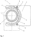
- Fig. 1 shows a schematic representation of a device 1 according to the invention, the device 1 for the contactless inspection of a butt weld containing a carrier device 2.
- the device 1 shown is purely schematic, which is why the carrier device 2 is also only shown as a rectangular plate 2.
- the carrier device 2 can have a different shape as well as further features such as a display or switch.
- a sensor carrier 3 is arranged on the carrier device 2.
- the sensor carrier 3 is arranged such that it can be rotated around the pipes to be welded or the welded pipes or the weld seam, preferably by 360 °, and thus around the complete pipe. This is with the in Fig.
- the embodiment shown is solved in that the sensor carrier 3 is driven by the two drives 8, which preferably run synchronously, and when the sensor carrier 3 is rotated about its central axis or around the pipe axis, at least one drive 8 is in engagement with the sensor carrier 3, which is why the drives 8 and the sensor carrier 3 preferably have teeth (not shown), the sensor carrier 3 also being drivable by other types.
- the sensor carrier 3 preferably has a C-shape.
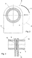
- this also has the advantage that the sensor carrier 3 can simply be moved over the pipe ends to be welded or over the pipes which have already been welded Fig. 2 is recognizable, and is then arranged concentrically to the tube 5, whereby the encircling of the sensor carrier 3 with the sensor 4 arranged thereon can be easily implemented in order to enable a check of the complete weld seam.
- the C-shape is designed in such a way that it is possible to move the sensor carrier 3 through the pipe, even with the largest pipe diameter to be checked, on the corresponding device 1.
- An electronic light-sensitive sensor 4 is arranged on the sensor carrier 3.
- Such sensors 4 are known from the prior art as CCD sensors or also CMOS sensors, such sensors 4 being located in digital cameras and instead of a sensor 4 which is combined with an optical system, a digital camera can also be used which has one Includes sensors 4. It is important for the installation of such a sensor 4 with the optics or the digital camera required for this that the sensor with the optics or the digital camera is of compact construction.
- Fig. 3 the space available for the device 1 according to the invention can be seen.
- the device 1 according to the invention must be insertable between the pipe clamps 10 and this requires a narrow sensor 4 and also the support device 2 and the sensor support 3 are to be designed very thin since these also protrude between the pipe clamps 10 and the pipe clamps 10 move relatively close together due to the welding process are.
- the device 1 according to the invention has lighting 6 so that the weld seam or welding bead recorded by the sensor 4 can be clearly recognized and the contour is clearly emphasized.
- the lighting 6 is disclosed as a back light 6, wherein in Fig. 1 the back light 6 is designed as a light screen 6. This ensures that all sizes of tube diameters that can be checked on the device 1 are ideally illuminated by the backlight 6.
- the dashed line represents the theoretical smallest pipe diameter, here the center of the pipes 5 was used as the smallest diameter.
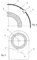
- Fig. 4 shows the lighting 6 executed as incident light.
- the incident light illuminates the weld seam at the location of the receptacle, the weld seam being recorded vertically by the sensor 4 or the digital camera onto the weld seam or the circumference of the tubes 5.
- This type of recording mainly recognizes contamination and irritation on the surface and / or the pipe or fitting material.
- Fig. 5 shows the schematic representation when using backlight 6.
- backlight 6 By using backlight 6, the contour of the weld seam or welding bead is clearly visible.
- sensor 4 must be directed tangentially to the tube diameter or to the weld seam.
- the backlight 6 radiates accordingly in the opposite direction.
- both the design of the backlight and incident light can be attached to the sensor carrier 3 in order to carry out the different checks, and there is also the possibility of individual use of backlight or incident light.
- Fig. 5 the smallest and the largest pipe diameter are shown for which the device 1 can be used.
- the sensor 4 therefore has a correspondingly large viewing angle ⁇ in order to cover the largest possible range of the possible pipe diameters which can be checked with the device 1.
- the backlight 6 Since the position of the backlight 6 also changes in accordance with the tube diameter and this is also arranged fixedly on the sensor carrier 3, the backlight 6 is formed by a light screen 6 which is concentric with the tube circumference or along the inner surface of the C-shape of the sensor carrier 3 extends. In Fig. 1 a corresponding light screen 6 is clearly visible. Lined-up LEDs can be used as possible illuminants, other illuminants also being conceivable.
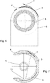
- Fig. 7 the area-wise switching on and off of the light screen 6 is shown
- the in Fig. 7 Embodiment of the device according to the invention shown also has a mirror 7 and the sensor 4 carries out the recording of the weld seam indirectly via the mirror 7.
- the backlight 6 shines in the opposite direction, with only a luminous region 12 of the backlight 6 being switched on, as a result of which reflection of the lighting vertically to the weld seam can be avoided and the recordings are therefore not disturbed and can be clearly recognized.
- the sensor carrier 3 rotates 360 ° around the weld seam or the pipe ends, during which the sensor 4 takes the pictures.
- Fig. 6 represents again the advantage of a mirror 7.
- the recording by the sensor 4 takes place tangentially with the backlight 6. So that the entire width of the weld seam or the weld bead is illuminated or surrounded by the back light 6, it is advantageous if the distance from the sensor 4 to the point of the weld seam is relatively large, this increases the perceived width of the back light 6 and enables complete coverage the width of the weld seam by means of backlight 6, as a result of which the contour of the weld seam or weld bead is clearly visible, this is also shown in the figures Fig. 9 good to see.
- the enlargement of the distance between the sensor and the weld seam also has the effect that the path difference (optical path) between the largest and smallest tube dimensions, in relative terms, becomes smaller.
- Fig. 8 represents the sequence for the arrangement around the tubes and their checking of the sensor carrier 3.
- the sensor carrier 3 is moved over the tubes 5, which enables the C-shape of the sensor carrier 3.
- the sensor carrier 3 with the sensor 4 arranged thereon, the mirror 7 and the lighting 6, which is designed here as a back light 6, surrounds the tube 5 can rotate, preferably by 360 ° so that the weld seam or the pipe ends can be completely checked.
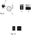
- Fig. 9 represents a schematic check according to the invention of the pipe ends before the welding and a check after the welding by checking the weld seam.
- the sensor 4 is directed tangentially to the pipe diameter of the pipe ends 5 to be welded or their weld seam after the weld and is tangent by backlight 6 irradiated.
- the sensor 4 detects the receptacle 13, 14.
- the receptacle 13 represents the two pipe ends 5 before the welding and, by holding the sensor 4, which can be carried out continuously or as individual receptacles, enables the detection of the diameters, the ovality and the mutual Offset, the surface condition, etc.
- the weld seam which is shown in the receptacle 14 can be recorded analogously.
- the geometry of the weld seam 9 or the weld bead 9, the shape, the size and the area as well as possible irritations and impurities can also be determined by the recording.
- This recorded data is then converted by the control in such a way that only the contour as in Fig. 10 mapped, processed or used for data comparison.
- These determined contours can then be compared by means of the standards and / or comparative values or boundary conditions stored in the control and result in the permissibility or inadmissibility of a weld seam or the pipe ends by assessing whether the corresponding weld seam meets the requirements based on their determined properties and dimensions Requirements are sufficient or not sufficient.
- the recorded data can also be saved for documentation purposes.
Landscapes
- Engineering & Computer Science (AREA)
- Mechanical Engineering (AREA)
- Physics & Mathematics (AREA)
- General Physics & Mathematics (AREA)
- Health & Medical Sciences (AREA)
- Analytical Chemistry (AREA)
- Life Sciences & Earth Sciences (AREA)
- Chemical & Material Sciences (AREA)
- Biochemistry (AREA)
- General Health & Medical Sciences (AREA)
- Immunology (AREA)
- Pathology (AREA)
- Toxicology (AREA)
- Computer Vision & Pattern Recognition (AREA)
- Signal Processing (AREA)
- Investigating Materials By The Use Of Optical Means Adapted For Particular Applications (AREA)
- Length Measuring Devices By Optical Means (AREA)
- Lining Or Joining Of Plastics Or The Like (AREA)
Description
- Die Erfindung betrifft eine Vorrichtung und ein Verfahren zur berührungslosen Überprüfung einer Stumpfschweissung von Kunststoffrohren und Fittingen, wobei die Vorrichtung eine Trägervorrichtung, eine Beleuchtung und mindestens einen Sensor aufweist, wobei die Rohrenden mittels bekanntem Stumpfschweissverfahren verschweisst werden und eine berührungslose Überprüfung der Schweissnaht sowie optionale Prüfung der Rohrenden bzw. Fittingenden vor der Schweissung mittels Sensor durchgeführt wird.
- Eine Überprüfung einer Stumpfschweissung dient der Qualitätssicherung der Schweissung. Es spielt keine Rolle mit welchem Verfahren die Rohre bzw. Fittings stumpfgeschweisst wurden, sei es mittel berührungslosem IR-Schweissverfahren, mittels des klassischen Stumpfschweissverfahrens durch berühren des Heizspiegels oder eines anderen Verfahrens. Entsprechend den zu verschweissenden Rohren bzw. Fittings, das heisst, ihren Abmassen, deren Kunststoff, der Schweisstechnologie die angewandt wird, usw. hat eine Schweissnaht eine gewisse Form bzw. Grösse aufzuweisen, die optisch überprüfbar ist. Entsprechend dazu existieren Richtlinien bzw. Normen, welche genau definieren wie eine Naht aussehen muss bzw. wie die zulässigen Abmasse in Bezug auf die Rohr- bzw. Fitting- und Schweisseigenschaften sein müssen, damit sie den Anforderungen entspricht. Bisher wurde meist eine manuelle optische Beurteilung durch eine zuständige Fachperson durchgeführt, die anhand der ihr bekannten Normen und Richtlinien die entstandene Schweissnaht vergleicht und beurteilt.
Nachteilig hierbei ist, dass Beurteilungen durch eine Fachperson sehr zeitintensiv und somit sehr teuer sind. Zudem ist eine solche Beurteilung auch nicht konstant gleich, da der menschliche Faktor eine wesentliche Rolle spielt und die Überprüfung nicht immer durch dieselbe Fachperson stattfindet. - Die
JP 2000289115A - Nachteilig an dieser Prüfung ist der hohe Aufwand da eine derartige Prüfung sehr zeitintensiv ist, da unteranderem die Schweissung vollständig erkaltet sein muss bevor eine solche Prüfung stattfinden kann, was für die Installation einer Rohrleitung mit diversen Schweissnähten nicht ideal ist.
-
US 2002/084260 A1 ,US 2004/179206 A1 ,DE 10 2012 007563 B3 ,DE 20 2014 100284 U1 ,US 2007/119829 A1 ,WO 2014/063153 A1 ,US 2010/314362 A1 undUS 6 084 203 A offenbaren Vorrichtungen zur berührungslosen Überprüfung von Schweissungen. Es ist Aufgabe der Erfindung eine Vorrichtung und ein damit verbundenes Verfahren vorzuschlagen, welches eine zerstörungsfreie bzw. berührungslose, konstante Qualitätsüberprüfung der Schweissung bei stumpfgeschweissten Kunststoffrohren ermöglicht, ohne dass ein wirtschaftlicher Nachteil durch einen höheren Zeitaufwand entsteht. - Diese Aufgabe wird erfindungsgemäss durch die Merkmalskombination des Anspruchs 1 bzw. des Anspruchs 9 gelöst. Vorteilhafte Weiterbildungen der Erfindung sind Gegenstand der abhängigen Ansprüche.
- Die erfindungsgemässe Vorrichtung enthält eine Trägervorrichtung, wobei dieses entsprechend der Anwendung der Vorrichtung bzw. ihrem Einsatzgebiet ausgelegt und gestaltet ist, wodurch die erfindungsgemässe Vorrichtung als autonome Prüfvorrichtung hergestellt werden kann oder aber auch als nachrüstbares Modul für eine existierende Stumpfschweissmaschine ausgebildet sein kann. Selbstverständlich kann die erfindungsgemässe Vorrichtung auch derart ausgebildet sein, dass sie bereits fest an einer Stumpfschweissmaschine integriert ist. Entsprechend der Anwendung ist auch eine Bedieneinheit vorzusehen oder kann darauf verzichtet werden, da ev. die Bedieneinheit der Schweissmaschine genutzt werden kann.
Zudem weist die Vorrichtung eine Beleuchtung auf um die Schweissnaht bzw. die Rohrenden während der Überprüfung bzw. der Aufnahmen mittels Sensor zu beleuchten, damit die Konturen der Schweissnaht bzw. Schweissraupe wie auch der Rohrenden vor dem Schweissprozess klar erkennbar sind. - Der Sensor bzw. die Digitalkamera macht Aufnahmen der Verschweissung bzw. der Schweissnaht sowie vor der Verschweissung der zu verschweissenden Rohrenden.
- Als elektronischer lichtempfindlicher Sensor kann ein CCD-Sensor, CMOS-Sensor oder ein anderer aus dem Stand der Technik bekannter elektronischer lichtempfindlicher Sensoren eingebaut werden, der eine kompakte Bauweise aufweist. Selbstverständlich kann auch eine Digitalkamera eingesetzt werden, da diese meist einen solchen Sensor beinhalten. Zudem sind die aus dem Stand der Technik bekannten Digitalkameras so klein, dass sie problemlos für die vorliegende Erfindung eingesetzt werden können. Die Aufnahmen der Schweissnaht bzw. der Rohrenden kann als Film bzw. kontinuierlich ablaufen oder es können auch einzelne Bildaufnahmen getätigt werden, die einzelnen getätigten Bildaufnahmen während einer Überprüfung einer Schweissnaht sind individuell wählbar. Der Sensor bzw. die Digitalkamera ist bewegbar bzw. beweglich am Sensorträger angeordnet bzw. kann entsprechend ausgerichtet werden, falls es nötig ist.
- Als bevorzugte Ausführungsform weist die erfindungsgemässe Vorrichtung einen Sensorträger auf. Der Sensor ist vorzugsweise am Sensorträger angeordnet und der Sensorträger wiederum an der Trägervorrichtung.
Vorteilhaft ist es, wenn der Sensorträger beweglich bzw. drehbar an der Trägervorrichtung angeordnet ist, dadurch ist der Sensorträger auf der Trägervorrichtung um eine Achse rotierbar, wobei die Trägervorrichtung eine feste Basis bildet. - Die Erfindung zeichnet sich dadurch aus, dass sich der Sensorträger 360° um das Rohr bzw. die Schweissung rotieren lässt. Dadurch bewegt sich der Sensor der am Sensorträger angeordnet ist ebenfalls um das Rohr mit und kann die komplette Schweissnaht bzw. die Rohrenden vor der Schweissung aufnehmen bzw. überprüfen.
- Der Sensorträger weist vorzugsweise eine C-Form auf. Diese ermöglicht ein einfaches Positionieren des Sensorträgers um den Rohrumfang indem der C-förmige Sensorträger über den Rohrumfang gefahren wird, da die Öffnung der C-Form derart gross ist, dass der grösste Rohrdurchmesser, der mit der erfindungsgemässen Vorrichtung überprüft werden kann durch die Öffnung der C-Form hindurch geschoben werden kann bzw. der Sensorträger über das Rohr geschoben werden kann. Die zu verschweissenden Rohrenden werden dann konzentrisch vom Sensorträger umgeben. Diese Form des Sensorträgers ermöglicht dem Sensorträger und somit auch dem Sensor das 360° umkreisen des Rohres bzw. der Schweissnaht. Vorzugsweise ist der Sensor derart am Sensorträger angeordnet, dass der Blickwinkel bzw. das Blickfeld des Sensors es ermöglicht unterschiedliche Rohrdimensionen mit derselben erfindungsgemässen Vorrichtung zu erfassen und zu überprüfen ohne einen Umbau oder eine Einstellung der Vorrichtung vornehmen zu müssen. Wie bereits erwähnt, ist der Sensor vorzugsweise beweglich am Sensorträger angeordnet, vorzugsweise schwenkbar, wodurch eine Feineinstellung des Sensors möglich ist.
- Der Sensor ist tangential auf den Rohrumfang ausgerichtet, bewährter Weise derart, dass wie zuvor bereits erwähnt, möglichst viele Dimensionen der Rohre mit einer Vorrichtung bzw. einer Sensoreinstellung erfasst werden können. Es ist zudem vorteilhaft, wenn die Beleuchtung ebenfalls in einem definierten Abstand zum Sensor am Sensorträger angeordnet ist und sich ebenfalls um das Rohr bzw. Schweissnaht mitbewegt. Eine bevorzugte Ausführung besteht darin, dass die Beleuchtung derart am Sensorträger angeordnet ist, dass sie ein Gegenlicht für den Sensor bildet.
Zu beachten ist bei der bevorzugten Ausführungsform bei der die Beleuchtung als Gegenlicht eingesetzt wird, dass auch hier die unterschiedlichen Rohrdurchmesser, für welche die Vorrichtung anwendbar ist, abdeckbar sind. Das heisst, dass sie ein Gegenlicht für den Sensor beim kleinsten wie auch beim grössten Durchmesser, der auf der Vorrichtung überprüfbar ist, bildet. Vorzugsweise ist die Beleuchtung deshalb als Licht-Screen ausgebildet, das heisst, die Beleuchtung erstreckt sich über einen bestimmten Bereich. Die am Sensorträger angeordnete Beleuchtung, wobei der Sensorträger vorzugsweise eine C-Form aufweist, erstreckt sich an der C-Form über eine bestimmte Länge, so dass jegliche Rohrdurchmesser entsprechend gut durch den Licht-Screen beleuchtet werden. Vornehmlich kann der Licht-Screen abschnittsweise an- bzw. ausgeschaltet werden, damit jeweils nur der Abschnitt des Licht-Screens leuchtet der das optimale Gegenlicht für den Sensor bildet. Bspw. können zur Beleuchtung LEDs eingesetzt werden, die entlang des Sensorträgers derart angeordnet sind, dass sie einen Licht-Screen bilden und abschnittsweise an- oder ausgeschaltet werden können. - Eine bevorzugte Ausführungsform besteht darin, dass die erfindungsgemässe Vorrichtung einen Spiegel aufweist, wobei der Spiegel vorzugsweise am Sensorträger angeordnet ist. Es ist Vorteilhaft, wenn der Spiegel beweglich am Sensorträger angeordnet ist, das ermöglicht eine Feinausrichtung des Spiegels. Der Spiegel dient dazu, den optischen Weg zwischen Sensor und der aufzunehmenden Schweissnaht zu vergrössern. Zudem wird der Blickwinkel zwischen Sensor und der Schweissnaht verändert. Der Sensor ist in dieser Ausführungsform der erfindungsgemässen Vorrichtung nicht direkt tangential auf den Rohrumfang gerichtet sondern wird über einen Spiegel indirekt tangential auf den Rohrleitungsumfang gerichtet. Es hat sich als Vorteilhaft gezeigt, dass der Spiegel und/oder der Sensors beweglich am Sensorträger angeordnet sind, damit eine Feineinstellung vorgenommen werden kann. Die Beleuchtung ist derart angeordnet, dass ein Gegenlicht gebildet wird, das heisst, das Gegenlicht strahlt tangential an den Rohrumfang und direkt in den Spiegel hinein, welcher das Licht an den Sensor umleitet. Dadurch bleibt die Distanz zwischen Gegenlicht und Schweissnaht, die tangential beleuchtet wird, gleich wie ohne Spiegel aber die Distanz zwischen Sensor bzw. der Digitalkamera und der Schweissnaht bzw. dem Rohrumfang an der Stelle an der die Aufnahme getätigt wird, vergrössert sich im Gegensatz zur Anordnung ohne Spiegel. Dadurch vergrössert sich die wahrgenommene Breite des Gegenlichts und ermöglicht eine Beleuchtung der kompletten Schweissnaht bzw. eine Abdeckung der ganzen Breite der Schweissraupe mittels des Gegenlichts wodurch die Schweissnaht komplett von hinten beleuchtet ist, ausgehend davon, dass der Abstand des Gegenlichts zur Schweissnaht konstant bleibt. Das wiederum dient der klaren Erkennung und Erfassung der Kontur der Schweissnaht bzw. der Schweissraupe während den Aufnahmen.
- Eine nicht erfindungsgemässe Vorrichtung besteht darin, dass die Beleuchtung als Auflicht am Sensorträger angeordnet ist sowie der Sensor bzw. die Digitalkamera senkrecht bzw. annähernd senkrecht auf den Aussendurchmesser der Rohrleitung bzw. der Schweissnaht gerichtet ist. Der Sensor ist deshalb annähern senkrecht ausgerichtet, damit eine Reflektionen der Beleuchtung an der Schweissnaht vermieden werden kann, wodurch die Aufnahmen klarer ausfallen. Durch diese Anordnung des Sensors und der Beleuchtung kann die Oberflächenbeschaffenheit der zu überprüfenden Stelle ermittelt werden. Wobei die Ausführung des tangentialen bzw. indirekt tangentialen Sensors mit dem Gegenlicht und der senkrecht auf den Umfang gerichtete Sensor mit dem Auflicht kombiniert wie auch separat am Sensorträger angeordnet sein können
- Das erfindungsgemässe Verfahren zur berührungslosen Überprüfung einer Stumpfschweissung von Kunststoffrohren zeichnet sich durch folgende Schritte aus: Die zu verschweissenden Rohrenden werden vorzugsweise mittels Rohrklemmen auf der Stumpfschweissmaschine befestigt, so dass sich die zwei zu verschweissenden Stirnseiten einander gegenüberliegen. Daraufhin werden die Rohrenden gehobelt damit saubere und plane Stirnseiten vorliegen und so für die Schweissung vorbereitet sind.
Vorzugsweise werden bereits die zu verschweissenden Rohrenden berührungslos überprüft, sobald sie in den Rohrklemmen bspw. auf der Stumpfschweissmaschine befestigt und gehobelt sind. Zum Beispiel können die Aussendurchmesser der zu verschweissenden Rohrenden sowie auch ihre Ovalität und ihr gegenseitiger Versatz zueinander überprüft und eventuell noch korrigiert werden. Oder zumindest können die Rohre bzw. ihre Fehler dadurch frühzeitig erkannt und aussortiert bzw. ersetzt werden. Zudem besteht die Möglichkeit bereits zu diesem Zeitpunkt mittels des erfindungsgemässen Verfahrens zu erkennen ob die Oberfläche der zu verschweissenden Rohrenden genügend sauber und glatt ist. Weitere Überprüfungen und Erkennungen wie Materialerkennung, Farberkennung, Parallelität der Rohre, usw. sind durch das erfindungsgemässe Verfahren ebenso vorstellbar. - Anschliessend kann die Verschweissung durchgeführt werden, wobei die zuvor durchgeführte berührungslose Überprüfung der Rohrenden kein Muss im Verfahren zur Überprüfung der Schweissnaht darstellt.
Zur Schweissung kann jegliches aus dem Stand der Technik bekanntes Verfahren angewandt werden wie bspw. eine IR-Schweissung, eine Stumpfschweissung mittels Berührung am Heizspiegel, usw..
Anschliessend erfolgt die berührungslose Überprüfung der Schweissnaht bzw. der Schweissraupe. Der grosse Vorteil hierbei besteht darin, dass die Überprüfung, da sie berührungslos ist, bereits während des Abkühlvorgangs erfolgen kann, wodurch ein zusätzlicher Zeitaufwand für eine nachträgliche Überprüfung nach dem Abkühlen vermieden werden kann, was ein rasches und zügiges Verlegen einer Rohrleitung ermöglicht. Die berührungslose Überprüfung wird mittels eines elektronischen lichtempfindlichen Sensors vorzugsweise einer Digitalkamera durchgeführt, sowohl zur Überprüfung der Schweissnaht wie auch dem optionalen Vorgang der Überprüfung der Rohrenden. Selbstverständlich sind die möglichen Ausführungsformen, wie zuvor in Bezug auf die Vorrichtung ausgeführt, auch auf das Verfahren anwendbar. Der Sensor erfasst die Kontur der Schweissnaht bzw. Schweissraupe, wie Breite, Form, usw. wodurch auch die Querschnittsfläche der Schweissnaht ermittelt werden kann. Falls auch eine Überprüfung der Rohrenden vor der Verschweissung stattgefunden hat wird auch die Kontur der Rohrenden und ihrer weiteren Eigenschaften erfasst und ev. bereits mittels Steuerung ausgewertet.
Der Sensor erfasst die Daten kontinuierlich bzw. als Film oder auch einzelne Aufnahmen entlang des Umfangs sind möglich. Dazu rotiert der Sensor um den Rohrumfang bzw. um die Schweissnaht, wodurch die komplette Naht erfasst und überprüft wird ohne die Rohre in ihrer Lage zu verändern.
Damit die ermittelten Aufnahmen scharfe und deutliche Konturen ergeben, wird die Schweissnaht beleuchtet, durch ein Gegenlicht auf den tangential bzw. indirekt tangential gerichteten Sensor, welches die Konturen der Schweissnaht bzw. der Schweissraupe bzw. der Rohrenden deutlich hervorhebt und gut erkennbar macht.
Diese durch den Sensor ermittelten Daten werden dann mit den in der Steuerung hinterlegten Daten, die auf Normen und/oder Richtlinien beruhen, die angeben welche Dimension und Form eine Schweissnaht für bestimmte Anforderungen mit den verschweissten Kunststoffrohren aufweisen muss damit sie den Anforderungen stand hält, abgeglichen und geprüft. Aufgrund dieser Auswertung kann dann ausgesagt werden ob die Schweissnaht den Anforderungen entspricht. Zudem kann durch den Sensor, welcher tangential oder indirekt tangential auf den Rohrumfang bzw. die Schweissnaht gerichtet ist und mit Auflicht beleuchtet wird auch ermittelt werden ob Irritationen oder Verunreinigungen auf der Oberfläche der Schweissnaht bzw. Schweissraupe vorliegen, welche ev. auch zu einer Schwächung der Schweissung führen können. All diese Auswertungen können mittels der Steuerung aufgrund der festgelegten Randbedingungen für die Schweissnaht erfolgen, welche in der Regel durch Normen definiert werden. Oder dem Benutzer werden die Daten (Mass- und Flächenangaben) bereitgestellt um als Entscheidungshilfe zu dienen.
Auch können die, durch die Vorrichtung erfassten Daten gespeichert werden, um den Schweissprozess bzw. das Schweissergebnis zu dokumentieren und/oder eine nachträgliche Beurteilung der Schweissnaht zu ermöglichen. - Die Ausführungsbeispiele der Erfindung werden anhand der Figuren beschrieben, wobei sich die Erfindung nicht nur auf die Ausführungsbeispiele beschränkt. Es zeigen:
- Fig. 1
- eine schematische Ansicht einer erfindungsgemässen Vorrichtung,
- Fig. 2
- eine schematische Ansicht einer erfindungsgemässen Vorrichtung, wobei nur der Sensorträger ohne Trägervorrichtung dargestellt ist,
- Fig. 3
- ein schematischer Längsschnitt durch die Rohrklemme und die verschweissten Rohrenden,
- Fig. 4
- eine schematische Darstellung einer nicht erfindungsgemässen Vorrichtung, wobei die Beleuchtung als Auflicht angeordnet ist,
- Fig. 5
- eine schematische Darstellung einer erfindungsgemässen Vorrichtung, wobei die Beleuchtung als Gegenlicht angeordnet ist,
- Fig. 6
- eine schematische Darstellung einer erfindungsgemässen Vorrichtung, mit Gegenlicht und Spiegel,
- Fig. 7
- eine schematische Darstellung einer erfindungsgemässen Vorrichtung, mit Licht-Screen, wobei der Licht-Screen nur bereichsweise leuchtet,
- Fig. 8
- eine schematische Darstellung des Bewegungsablaufs des Sensorträgers,
- Fig. 9
- eine schematische Anordnung des Sensors, des Rohres und der Beleuchtung mit den erfassten Aufnahmen durch den Sensor und
- Fig.10
- die umgewandelte Aufnahme in die reine Kontur zur Ermöglichung des Vergleichs.
-
Fig. 1 zeigt eine schematische Darstellung einer erfindungsgemässen Vorrichtung 1, wobei die Vorrichtung 1 zur berührungslosen Überprüfung einer Stumpfschweissung eine Trägervorrichtung 2 enthält. Die inFig. 1 dargestellte Vorrichtung 1 ist rein schematisch, weshalb die Trägervorrichtung 2 ebenfalls nur als rechteckige Platte 2 dargestellt ist. Selbstverständlich kann die Trägervorrichtung 2 eine andere Form wie auch weitere Features wie bspw. eine Anzeige oder Schalter aufweisen. Zudem sollte sie auch entsprechend der Anwendung der Vorrichtung 1 ausgelegt sein, dass sie zum bsp. so ausgebildet ist, dass sie an eine Stumpfschweissmaschine adaptierbar ist und bspw. durch Einschwenken zwischen die Rohrklemmen 10 inFig. 3 , analog eines Heizspiegels, in der Stumpfschweissmaschine platzierbar ist. Selbstverständlich sind auch andere Adaptierungen an eine Schweissmaschine denkbar. Durch einen modularen Aufbau der erfindungsgemässen Vorrichtung 1 ist sie beliebig einsetzbar und eignet sich auch zur Nachrüstung. Die Vorrichtung 1 kann auch autonom ausgebildet sein und eine eigene Steuerung und Anzeige aufweisen. An der Trägervorrichtung 2 angeordnet ist ein Sensorträger 3. Der Sensorträger 3 ist derart angeordnet, dass er um die zu verschweissenden Rohre bzw. die verschweissten Rohre bzw. die Schweissnaht rotierbar ist, vorzugsweise um 360°, somit um das komplette Rohr herum. Dies wird mit der inFig. 1 dargestellten Ausführungsform dadurch gelöst, indem der Sensorträger 3 durch die beiden Antriebe 8, welche vorzugsweise synchron laufen, angetrieben wird und beim Drehen des Sensorträgers 3 um dessen Mittelachse bzw. um die Rohrleitungsachse sich mindestens jeweils ein Antrieb 8 im Eingriff mit dem Sensorträger 3 befindet, weshalb die Antriebe 8 sowie der Sensorträger 3 vorzugsweise eine Verzahnung aufweisen (nicht dargestellt), wobei der Sensorträger 3 auch durch andere Arten antreibbar ist. - Der Sensorträger 3 weist vorzugsweise eine C-Form auf. Dieses bringt neben dem Vorteil der guten Rotationsmöglichkeit auch den Vorteil mit sich, dass der Sensorträger 3 einfach über die zu verschweissenden Rohrenden bzw. über die bereits verschweissten Rohre rüber gefahren werden kann, was in
Fig. 2 erkennbar ist, und anschliessend konzentrisch zum Rohr 5 angeordnet ist wodurch das Umkreisen des Sensorträgers 3 mit dem darauf angeordneten Sensor 4 einfach realisierbar ist um eine Überprüfung der kompletten Schweissnaht zu ermöglichen. Die C-Form ist derart ausgebildet, dass ein über das Rohrfahren des Sensorträgers 3 auch beim grössten zu überprüfenden Rohrdurchmesser auf der entsprechenden Vorrichtung 1 möglich ist.
Am Sensorträger 3 ist ein elektronischer lichtempfindlicher Sensor 4 angeordnet. Aus dem Stand der Technik sind solche Sensoren 4 als CCD-Sensoren oder auch CMOS-Sensoren bekannt, wobei sich solche Sensoren 4 in Digitalkameras befinden und anstelle eines Sensors 4 der mit einer Optik kombiniert ist, kann auch eine Digitalkamera eingesetzt werden, die einen solchen Sensoren 4 beinhaltet.
Wichtig ist für den Einbau eines solchen Sensors 4 mit einer dazu benötigten Optik bzw. der Digitalkamera, dass der Sensor mit der Optik bzw. die Digitalkamera kompakt gebaut ist. InFig. 3 sind die Platzverhältnisse für die erfindungsgemässe Vorrichtung 1 erkennbar. Die erfindungsgemässe Vorrichtung 1 muss zwischen die Rohrklemmen 10 einschiebbar sein und dies erfordert einen schmalen Sensor 4 sowie auch die Trägervorrichtung 2 und der Sensorträger 3 sehr dünn auszulegen sind da diese auch noch zwischen die Rohrklemmen 10 hineinragen und die Rohrklemmen 10 durch den Schweissvorgang relativ nahe zusammengefahren sind. Zudem weist die erfindungsgemässe Vorrichtung 1 eine Beleuchtung 6 auf, damit die vom Sensor 4 aufgenommene Schweissnaht bzw. Schweissraupe deutlich erkennbar ist und sich die Kontur klar hervorhebt. InFig. 1 ist die Beleuchtung 6 als Gegenlicht 6 offenbart, wobei inFig. 1 das Gegenlicht 6 als Licht-Screen 6 ausgebildet ist. Damit wird erzielt, dass alle Grössen von Rohrdurchmessern die auf der Vorrichtung 1 überprüfbar sind ideal vom Gegenlicht 6 beleuchtet werden. InFig. 1 stellt die gestrichelte Linie den theoretischen kleinsten Rohrdurchmesser dar, wobei hier das Zentrum der Rohre 5 stellvertretend als kleinsten Durchmesser eingesetzt wurde. AusFig. 1 ist somit erkennbar, dass die Erfassung der Schweissnaht mittels Sensor 4 und der entsprechenden Beleuchtung durch das Gegenlichts 6 von einem minimalen Rohrdurchmesser bis zu einem maximalen Rohrdurchmesser, welcher hier dargestellt ist, möglich ist ohne eine Veränderung an der Vorrichtung 1 vornehmen zu müssen, wobei der Sensor 4 bzw. die Digitalkamera 4 und/oder der Spiegel 7 bewegbar bzw. beweglich am Sensorträger 3 angeordnet sein können, um einerseits den Bereich der erfassbaren Rohrdurchmesser zu erweitern und andererseits eine Feineinstellung für eine optimale Aufnahme vornehmen zu können. Des Weiteren ist es von Vorteil, wenn die Vorrichtung 1 einen Spiegel 7 aufweist, da dieser den optischen Weg vom Sensor 4 zur Schweissnaht vergrössert, wie inFig. 1 ersichtlich. -
Fig. 4 zeigt die Beleuchtung 6 als Auflicht ausgeführt. Das Auflicht beleuchtet die Schweissnaht an der Stelle der Aufnahme, wobei die Aufnahme der Schweissnaht durch den Sensor 4 bzw. die Digitalkamera vertikal auf die Schweissnaht bzw. den Umfang der Rohre 5 erfolgt. Durch diese Art der Aufnahme werden hauptsächlich Verunreinigungen und Irritationen an der Oberfläche erkannt und/oder das Rohr- bzw. Fittingmaterial identifiziert.
Fig. 5 zeigt die schematische Darstellung bei der Verwendung von Gegenlicht 6. Durch die Verwendung des Gegenlichts 6 zeichnet sich die Kontur der Schweissnaht bzw. Schweissraupe deutlich ab Bei der Verwendung von Gegenlicht 6 muss der Sensor 4 tangential auf den Rohrdurchmesser bzw. auf die Schweissnaht gerichtet sein. In entgegengesetzter Richtung strahlt entsprechend das Gegenlicht 6. Selbstverständlich können sowohl die Ausführung des Gegen- und Auflichts am Sensorträger 3 befestigt sein um die unterschiedlichen Überprüfungen durchzuführen wie auch die Möglichkeit der Einzelanwendung von Gegenlicht oder Auflicht besteht. InFig. 5 sind jeweils der kleinste und der grösste Rohrdurchmesser abgebildet für die die Vorrichtung 1 anwendbar ist. Der Sensor 4 weist deshalb einen entsprechend grossen Blickwinkel α auf um einen möglichst grossen Bereich der möglichen Rohrdurchmesser abzudecken die mit der Vorrichtung 1 geprüft werden können. Da sich entsprechend der Rohrdurchmesser auch die Position des Gegenlichts 6 ändert und dieses aber auch fest am Sensorträger 3 angeordnet ist, wird das Gegenlicht 6 durch einen Licht-Screen 6 gebildet der sich konzentrisch zum Rohrumfang bzw. entlang der Innenfläche der C-Form des Sensorträgers 3 erstreckt. InFig. 1 ist ein entsprechender Licht-Screen 6 gut erkennbar. Als mögliche Leuchtkörper können aneinandergereihte LEDs eingesetzt werden, wobei auch andere Leuchtkörper vorstellbar sind. - In
Fig. 7 ist die bereichsweise An- und Ausschaltung des Licht-Screens 6 dargestellt, wobei die inFig. 7 abgebildete Ausführungsform der erfindungsgemässen Vorrichtung noch einen Spiegel 7 aufweist und der Sensor 4 die Aufnahme der Schweissnaht indirekt über den Spiegel 7 ausführt. Aber auch hier strahlt das Gegenlicht 6 in die entgegengesetzte Richtung, wobei nur ein leuchtender Bereich 12 des Gegenlichts 6 angeschaltet ist, wodurch eine Reflektion der Beleuchtung vertikal zur Schweissnaht vermieden werden kann und dadurch die Aufnahmen nicht gestört werden und eindeutiger erkennbar sind. Dabei muss immer berücksichtigt werden, dass sich der Sensorträger 3 360° um die Schweissnaht bzw. die Rohrenden dreht, während dem der Sensor 4 die Aufnahmen tätigt.Fig. 6 stellt nochmals den Vorteil eines Spiegels 7 dar. Wie bereits erwähnt erfolgt mit Gegenlicht 6 die Aufnahme durch den Sensor 4 tangential. Damit die komplette Breite der Schweissnaht bzw. der Schweissraupe beleuchtet ist bzw. vom Gegenlicht 6 umgeben ist, ist es Vorteilhaft wenn die Distanz vom Sensor 4 zum Aufnahmepunkt der Schweissnaht relativ gross ist, das vergrössert die wahrgenommene Breite des Gegenlichts 6 und ermöglicht die komplette Abdeckung der Schweissnahtbreite mittels Gegenlicht 6, wodurch sich die Kontur der Schweissnaht bzw. Schweissraupe klar abzeichnet, dies ist auch in den Abbildungen ausFig. 9 gut erkennbar.
Die Vergrösserung des Abstandes zwischen dem Sensor und der Schweissnaht bewirkt auch, dass der Wegunterschied (optischer Weg) zwischen der grössten und kleinsten Rohrdimension, relativ betrachtet, kleiner wird. Dadurch kann auf eine Verstellung der Schärfentiefe verzichtet werden. Das Bild bleibt bei jeder Dimension scharf bzw. klar erkennbar.
Auch inFig. 6 sind die Varianten des möglichen minimalen und maximalen Rohrdurchmessers abgebildet, wenn auch der kleinste Durchmesser nur mittels gestrichelter Tangente an den fiktiven kleinsten Durchmesser angegeben ist, wobei auch hier wie auch inFig. 7 eine Erweiterung des erfassbaren Bereichs durch einen beweglichen Sensor und/oder Spiegel möglich ist. -
Fig. 8 stellt den Ablauf zur Anordnung um die Rohre und deren Überprüfung des Sensorträges 3 dar. Zu Beginn wird der Sensorträger 3 über die Rohre 5 gefahren, was die C-Form des Sensorträgers 3 ermöglicht. Des Weiteren wird aufgezeigt, dass sich der Sensorträger 3 mit dem daran angeordneten Sensor 4, dem Spiegel 7 und der Beleuchtung 6, welche hier als Gegenlicht 6 ausgebildet ist, um das Rohr 5 rotieren lässt, vorzugsweise um 360° damit die Schweissnaht bzw. die Rohrenden komplett überprüfbar sind.
Fig. 9 stellt eine schematische erfindungsgemässe Überprüfung der Rohrenden vor der Schweissung und eine Überprüfung nach der Schweissung durch die Überprüfung der Schweissnaht dar. Der Sensor 4 ist tangential auf den Rohrdurchmesser der zu verschweissenden Rohrenden 5 bzw. derer Schweissnaht nach der Schweissung gerichtet und wird tangential durch Gegenlicht 6 bestrahlt. Der Sensor 4 erfasst die Aufnahme 13, 14. Die Aufnahme 13 stellt die beiden Rohrenden 5 vor der Verschweissung dar und ermöglicht durch die Aufnahme des Sensors 4, welche kontinuierlich oder als einzelne Aufnahmen erfolgen kann, das Erfassen der Durchmesser, der Ovalität, des gegenseitigen Versatzes, der Oberflächenbeschaffenheit, usw.. Analog kann die Schweissnaht erfasst werden, die in der Aufnahme 14 dargestellt ist. Dabei kann auch durch die Aufnahme die Geometrie der Schweissnaht 9 bzw. der Schweissraupe 9 ermittelt werden, die Form, die Grösse die Fläche sowie ev. Irritationen und Verunreinigungen.
Diese erfassten Daten werden dann durch die Steuerung derart umgewandelt, dass nur noch die Kontur wie inFig. 10 abgebildet, weiter verarbeitet bzw. zum Datenvergleich eingesetzt wird. Diese ermittelten Konturen können anschliessend durch die in der Steuerung hinterlegten Normen und/oder Vergleichswerte bzw. Randbedingungen verglichen werden und ergeben die Zulässigkeit oder die nicht Zulässigkeit einer Schweissnaht bzw. der Rohrenden, indem aufgrund ihrer ermittelten Eigenschaften und Abmasse beurteilt wird ob die entsprechende Schweissnaht den Anforderungen genügt oder nicht genügt. Die erfassten Daten können auch zu dokumentationszwecken gespeichert werden. -
- 1
- Vorrichtung zur berührungslosen Überprüfung einer Stumpfschweissung
- 2
- Trägervorrichtung
- 3
- Sensorträger
- 4
- Sensor, elektronischer lichtempfindlicher Sensor, Digitalkamera
- 5
- Rohr, Rohrenden bzw. Fitting, Fittingenden
- 6
- Beleuchtung / Licht-Screen /Gegenlicht / Auflicht
- 7
- Spiegel
- 8
- Antrieb
- 9
- Schweissnaht
- 10
- Rohrklemme bzw. Fittingklemme
- 11
- Stumpfschweissnaht
- 12
- Leuchtender Bereich des Licht-Screens
- 13
- Rohrendenaufnahme durch Sensor vor Verschweissung
- 14
- Schweissnahtaufnahme durch Sensor
- α
- Blickwinkel Sensor
Claims (10)
- Vorrichtung (1) zur berührungslosen Überprüfung einer Stumpfschweissung von Kunststoffrohren und Fittingen (5) enthaltend eine Trägervorrichtung (2), eine Beleuchtung (6) um die Schweissnaht bzw. die Rohrenden während der Überprüfung bzw. der Aufnahmen mittels Sensor zu beleuchten, einen Sensorträger (3) und mindestens einen Sensor (4) zur Kontrolle der zu verschweissenden Rohrenden bzw. Fittingenden (5) sowie der Schweissnaht (9), wobei der Sensor (4) am Sensorträger (3) angeordnet ist, wobei der Sensorträger (3) beweglich bzw. drehbar an der Trägervorrichtung (2) angeordnet ist, wobei der Sensorträger (3) derart angeordnet ist, dass der Sensorträger (3) um die zu verschweissenden Rohre bzw. die verschweissten Rohre bzw. die Schweissnaht rotierbar ist, wobei der Sensor (4) ein elektronischer lichtempfindlicher Sensor (4), vorzugsweise eine Digitalkamera (4) ist, wobei der Sensor (4) tangential oder indirekt tangential auf den Rohrumfang bzw. die Schweissnaht gerichtet ist.
- Vorrichtung (1) nach Anspruch 1, wobei der Sensorträger (3) 360° um die zu verschweissende Rohre (5) bzw. Schweissnaht (9) drehbar ist.
- Vorrichtung (1) nach einem der Ansprüche 1 oder 2, wobei der Sensorträger (3) eine C-Form aufweist.
- Vorrichtung (1) nach einem der vorangehenden Ansprüche, wobei die Beleuchtung (6) am Sensorträger (3) angeordnet ist.
- Vorrichtung (1) nach einem der vorangehenden Ansprüche, wobei die Beleuchtung (6) als Gegenlicht (6) angeordnet ist.
- Vorrichtung (1) nach einem der vorangehenden Ansprüche, wobei die Vorrichtung einen Spiegel (7) aufweist, wobei der Spiegel (7) vorzugsweise am Sensorträger (3) angeordnet ist.
- Vorrichtung (1) nach einem der vorangehenden Ansprüche, wobei die Beleuchtung (6) als Auflicht angeordnet ist.
- Vorrichtung (1) nach einem der vorangehenden Ansprüche, wobei die Vorrichtung (1) an einer Stumpfschweissmaschine (11) angeordnet oder als ein autonomes Modul ausgebildet ist, wobei das Modul auch zur Nachrüstung an eine Stumpfschweissmaschine (11) adaptierbar ist.
- Verfahren zur berührungslosen Überprüfung einer Stumpfschweissung von Kunststoffrohren und Fittingen (5) mit folgenden Schritten:- einspannen bzw. fixieren der zu verschweissenden Rohrenden (5) mit sich gegenüberliegenden Stirnseiten- hobeln der Rohrenden- vorzugsweise durchführen einer berührungslosen Überprüfung der Rohrenden (5)- verschweissen der Rohrenden (5) mittels eines bekannten Stumpfschweissverfahrens- durchführen einer berührungslosen Überprüfung der Schweissnaht (9) während des Abkühlvorgangs,wobei die berührungslose Überprüfung mittels eines elektronischen lichtempfindlichen Sensors (4), vorzugsweise einer Digitalkamera (4) durchgeführt wird, wobei der Sensor (4) tangential oder indirekt tangential auf den Rohrumfang bzw. die Schweissnaht gerichtet und zur berührungslosen Überprüfung um die Rohrenden (5) bzw. Schweissnaht (9) rotiert wird, vorzugsweise um 360°.
- Verfahren nach Anspruch 9, wobei das Rohr (5) bzw. die Schweissnaht (9) beleuchtet wird, vorzugsweise mittels Gegenlicht oder Auflicht(6).
Priority Applications (5)
| Application Number | Priority Date | Filing Date | Title |
|---|---|---|---|
| EP14175829.2A EP2963380B2 (de) | 2014-07-04 | 2014-07-04 | Berührungsloses Überprüfen einer Stumpfschweissung |
| KR1020150089512A KR102388638B1 (ko) | 2014-07-04 | 2015-06-24 | 맞대기 용접의 무접촉 검사를 위한 디바이스 및 방법 |
| US14/748,419 US9816943B2 (en) | 2014-07-04 | 2015-06-24 | Contactless examination of a butt weld |
| CN201510387301.9A CN105241375B (zh) | 2014-07-04 | 2015-07-06 | 对接焊接的无接触检查 |
| KR1020220038195A KR20220044465A (ko) | 2014-07-04 | 2022-03-28 | 맞대기 용접의 무접촉 검사 |
Applications Claiming Priority (1)
| Application Number | Priority Date | Filing Date | Title |
|---|---|---|---|
| EP14175829.2A EP2963380B2 (de) | 2014-07-04 | 2014-07-04 | Berührungsloses Überprüfen einer Stumpfschweissung |
Publications (4)
| Publication Number | Publication Date |
|---|---|
| EP2963380A1 EP2963380A1 (de) | 2016-01-06 |
| EP2963380B1 true EP2963380B1 (de) | 2020-01-08 |
| EP2963380B8 EP2963380B8 (de) | 2020-02-26 |
| EP2963380B2 EP2963380B2 (de) | 2025-06-25 |
Family
ID=51162513
Family Applications (1)
| Application Number | Title | Priority Date | Filing Date |
|---|---|---|---|
| EP14175829.2A Active EP2963380B2 (de) | 2014-07-04 | 2014-07-04 | Berührungsloses Überprüfen einer Stumpfschweissung |
Country Status (4)
| Country | Link |
|---|---|
| US (1) | US9816943B2 (de) |
| EP (1) | EP2963380B2 (de) |
| KR (2) | KR102388638B1 (de) |
| CN (1) | CN105241375B (de) |
Families Citing this family (19)
| Publication number | Priority date | Publication date | Assignee | Title |
|---|---|---|---|---|
| EP3257656B1 (de) | 2016-06-16 | 2018-12-05 | Georg Fischer Rohrleitungssysteme AG | Rohrendenerkennung |
| DE102016012727A1 (de) * | 2016-10-24 | 2018-04-26 | Blum-Novotest Gmbh | Messsystem zur Messung an Werkzeugen in einer Werkzeugmaschine |
| US10702941B2 (en) | 2017-02-27 | 2020-07-07 | General Electric Technology Gmbh | System, method and apparatus for welding tubes |
| CN107525851B (zh) * | 2017-09-05 | 2020-02-11 | 北京工业大学 | 基于操作手杖的可拆装式纵向模态导波磁致伸缩传感器 |
| EP3550256B1 (de) | 2018-04-05 | 2021-03-10 | Georg Fischer Rohrleitungssysteme AG | Erkennung einer schweissnahtgeometrie |
| EP3550291A1 (de) | 2018-04-05 | 2019-10-09 | Georg Fischer Rohrleitungssysteme AG | Befestigungsvorrichtung für messgeräte an rohren |
| US10906080B2 (en) | 2018-04-16 | 2021-02-02 | Ford Motor Company | System and methods to radially orient extruded tubing for vehicle body component |
| CN109501281B (zh) * | 2018-11-23 | 2020-11-17 | 苏州昕源辰机械设备有限公司 | 一种pvc管旋转焊接装置 |
| KR102185790B1 (ko) * | 2019-02-22 | 2020-12-02 | 한양이엔지 주식회사 | 융착 파이프의 융착 비드 검사 장치 |
| FR3095274B1 (fr) * | 2019-04-19 | 2021-04-02 | Framatome Sa | Dispositif de contrôle d’une soudure d’un élément tubulaire longitudinal creux |
| KR102262585B1 (ko) * | 2019-11-12 | 2021-06-08 | 주식회사 명진티에스알 | 용접부의 검사용 캐리어 장치 |
| KR102174209B1 (ko) * | 2019-12-16 | 2020-11-04 | 주식회사 미성 | 복합관의 제조장치 및 그를 이용한 제조방법 |
| KR102594309B1 (ko) * | 2020-04-20 | 2023-10-27 | (주)아그루코리아 | 용접 비드 검사 장치 |
| KR102307971B1 (ko) * | 2020-12-24 | 2021-10-06 | 범아유니텍(주) | 강구 외관 검사장치 |
| EP4194184B1 (de) | 2021-12-07 | 2025-07-16 | Georg Fischer Rohrleitungssysteme AG | Schweissungsbeurteilung während schweissprozess |
| CN114384070A (zh) * | 2022-01-13 | 2022-04-22 | 江苏核电有限公司 | 用于汽轮发电机低压缸进汽管隔热板的焊缝检查设备 |
| WO2024008425A1 (en) * | 2022-07-04 | 2024-01-11 | Tetra Laval Holdings & Finance S.A. | A method for assessing a sealing of a carton package and an apparatus thereof |
| EP4450262A1 (de) * | 2023-04-18 | 2024-10-23 | Georg Fischer Rohrleitungssysteme AG | Stirnflächenbeurteilung |
| CN118392888B (zh) * | 2024-04-19 | 2024-10-15 | 北京锐业制药(潜山)有限公司 | 一种粉液双室袋管盖焊接质量检测系统 |
Citations (8)
| Publication number | Priority date | Publication date | Assignee | Title |
|---|---|---|---|---|
| EP0959344A1 (de) | 1998-05-20 | 1999-11-24 | COMPRA Gesellschaft für Qualitätssicherung und Umweltschutz mbH | Verfahren und Baugruppe zur Durchführung von Durchstrahlungsprüfungen an Werkstoffeinheiten |
| US6084203A (en) * | 1996-08-08 | 2000-07-04 | Axal | Method and device for welding with welding beam control |
| WO2008125102A1 (de) | 2007-04-12 | 2008-10-23 | V & M Deutschland Gmbh | Verfahren und vorrichtung zur optischen vermessung von aussengewinden |
| WO2011023960A1 (en) | 2009-08-28 | 2011-03-03 | Shawcor Ltd. | Method and apparatus for external pipeline weld inspection |
| WO2013064838A1 (en) | 2011-11-02 | 2013-05-10 | Johnson Matthey Public Limited Company | Scanning method and apparatus |
| DE102012007563B3 (de) | 2012-04-10 | 2013-05-29 | Salzgitter Mannesmann Line Pipe Gmbh | Vorrichtung zum Verbinden der Enden von Rohren aus Stahl mittels Orbitalschweißen |
| WO2013076541A1 (en) | 2011-11-24 | 2013-05-30 | Weldobot Ltd | System and method for modular portable welding and seam tracking |
| DE202014100284U1 (de) | 2014-01-23 | 2014-02-18 | Illinois Tool Works Inc. | Vorrichtung zum Ausrichten und Verschweissen von Gegenständen |
Family Cites Families (28)
| Publication number | Priority date | Publication date | Assignee | Title |
|---|---|---|---|---|
| US4160386A (en) * | 1977-06-09 | 1979-07-10 | Southwest Research Institute | Ultrasonic inspection system including apparatus and method for tracking and recording the location of an inspection probe |
| NL7904973A (nl) * | 1979-06-26 | 1980-12-30 | Roentgen Tech Dienst Bv | Stelsel voor het met ultrasone golven onderzoeken van lasverbindingen in pijpen. |
| JPS5841347A (ja) * | 1981-09-04 | 1983-03-10 | Hitachi Ltd | 溶接部検出装置 |
| US4429211A (en) * | 1982-08-02 | 1984-01-31 | United Technologies Corporation | Laser pipe welding system for nonstationary pipe |
| US4734766A (en) * | 1985-08-19 | 1988-03-29 | Kawasaki Steel Corporation | Method and system for locating and inspecting seam weld in metal seam-welded pipe |
| US5263362A (en) * | 1992-06-10 | 1993-11-23 | Fluoroware, Inc. | Weld test tool |
| US5347101A (en) * | 1994-02-07 | 1994-09-13 | Mcdermott International, Inc. | Automatic tracking system for pipeline welding |
| AU2241695A (en) * | 1994-07-18 | 1996-02-16 | Babcock & Wilcox Co., The | Sensor transport system for flash butt welder |
| DE19724986C2 (de) * | 1997-06-13 | 1999-07-29 | Jurca Optoelektronik Gmbh | Verfahren zum Verschweißen von Werkstücken und Vorrichtung zu dessen Durchführung |
| US5837966A (en) * | 1997-07-23 | 1998-11-17 | Timmons, Jr.; John E. | Apparatus for weld head to pipe joint alignment for welding |
| IL125200A0 (en) * | 1997-09-01 | 1999-03-12 | Fischer Georg Rohrleitung | An apparatus for butt welding of articles made of thermoplastic material |
| ID20783A (id) * | 1997-09-01 | 1999-03-04 | Fischer Georg Rohrleitung | Metode pengelasan bersama-sama, benda-benda yang terbuat dari bahan plastik |
| JP2000289115A (ja) | 1999-04-06 | 2000-10-17 | Kubota Corp | プラスチック管突合せ融着部の検査方法 |
| KR20010029268A (ko) * | 1999-09-30 | 2001-04-06 | 정주호 | 자동차용 박판의 맞대기 레이저 용접 모니터링 방법 |
| CN2460987Y (zh) * | 2000-09-15 | 2001-11-21 | 清华大学 | 焊缝路径轨迹线实时检测装置 |
| AT413954B (de) * | 2000-11-02 | 2006-07-15 | Fronius Int Gmbh | Erfassungselement für ein schweissgerät |
| JP3424001B2 (ja) * | 2000-12-28 | 2003-07-07 | 川崎重工業株式会社 | レーザ溶接方法およびレーザ溶接装置 |
| AU2002246960A1 (en) * | 2001-01-09 | 2002-08-06 | Edison Welding Institute | Non-destructive butt weld inspection method |
| FR2840991B1 (fr) * | 2002-06-17 | 2005-05-06 | Air Liquide | Procede de controle par ultrasons de joints soudes |
| EP1534466B1 (de) * | 2002-07-17 | 2007-04-18 | Shell Internationale Researchmaatschappij B.V. | Schmiedeschweissverfahren |
| DE10311247B8 (de) * | 2003-03-14 | 2008-05-08 | Inos Automationssoftware Gmbh | Portable Einrichtung zum Erfassen einer Lage und von Abmessungen eines Objekts |
| CN100522453C (zh) * | 2003-12-10 | 2009-08-05 | 菲茨有限责任公司 | 用于管道架设的轨道焊接装置 |
| CN1289252C (zh) * | 2004-10-21 | 2006-12-13 | 上海交通大学 | 焊缝自主跟踪方法 |
| KR100797239B1 (ko) * | 2005-12-23 | 2008-01-23 | 주식회사 포스코 | 강판의 용접부 온라인 검출장치 및 방법 |
| US8104347B2 (en) * | 2008-07-16 | 2012-01-31 | Röntgen Technische Dienst B.V. | Ultrasonic inspection method and device for plastics walls |
| US8552337B2 (en) * | 2009-06-11 | 2013-10-08 | Illinois Tool Works Inc. | Weld defect detection systems and methods for laser hybrid welding |
| US8739574B2 (en) * | 2011-09-21 | 2014-06-03 | Polaronyx, Inc. | Method and apparatus for three dimensional large area welding and sealing of optically transparent materials |
| MY173547A (en) * | 2012-10-19 | 2020-02-04 | Ipg Photonics Corp | Robotic laser seam stepper |
-
2014
- 2014-07-04 EP EP14175829.2A patent/EP2963380B2/de active Active
-
2015
- 2015-06-24 US US14/748,419 patent/US9816943B2/en active Active
- 2015-06-24 KR KR1020150089512A patent/KR102388638B1/ko active Active
- 2015-07-06 CN CN201510387301.9A patent/CN105241375B/zh active Active
-
2022
- 2022-03-28 KR KR1020220038195A patent/KR20220044465A/ko not_active Ceased
Patent Citations (8)
| Publication number | Priority date | Publication date | Assignee | Title |
|---|---|---|---|---|
| US6084203A (en) * | 1996-08-08 | 2000-07-04 | Axal | Method and device for welding with welding beam control |
| EP0959344A1 (de) | 1998-05-20 | 1999-11-24 | COMPRA Gesellschaft für Qualitätssicherung und Umweltschutz mbH | Verfahren und Baugruppe zur Durchführung von Durchstrahlungsprüfungen an Werkstoffeinheiten |
| WO2008125102A1 (de) | 2007-04-12 | 2008-10-23 | V & M Deutschland Gmbh | Verfahren und vorrichtung zur optischen vermessung von aussengewinden |
| WO2011023960A1 (en) | 2009-08-28 | 2011-03-03 | Shawcor Ltd. | Method and apparatus for external pipeline weld inspection |
| WO2013064838A1 (en) | 2011-11-02 | 2013-05-10 | Johnson Matthey Public Limited Company | Scanning method and apparatus |
| WO2013076541A1 (en) | 2011-11-24 | 2013-05-30 | Weldobot Ltd | System and method for modular portable welding and seam tracking |
| DE102012007563B3 (de) | 2012-04-10 | 2013-05-29 | Salzgitter Mannesmann Line Pipe Gmbh | Vorrichtung zum Verbinden der Enden von Rohren aus Stahl mittels Orbitalschweißen |
| DE202014100284U1 (de) | 2014-01-23 | 2014-02-18 | Illinois Tool Works Inc. | Vorrichtung zum Ausrichten und Verschweissen von Gegenständen |
Non-Patent Citations (2)
| Title |
|---|
| ANDREA SPITZER: "Verwendung von Spiegeln zur vollständigen photogrammetrischen Oberflächenrekonstruktion von schwer zugänglichen Objekten", DIPLOMARBEIT, September 2009 (2009-09-01), pages ii-iv, 1 - 62, XP055742867, Retrieved from the Internet <URL:https://publik.tuwien.ac.at/files/PubDat_178059.pdf> |
| ANONYMOUS: "DVS 2207 Teil 1 - Schweißen von thermoplastischen Kunststoffen Heizelementschweißen von Rohren, Rohrleitungsteilen und Tafeln aus PE-HD", DVS RICHTLINIE, August 1995 (1995-08-01), pages 184 - 195, XP055742860 |
Also Published As
| Publication number | Publication date |
|---|---|
| KR20220044465A (ko) | 2022-04-08 |
| EP2963380B2 (de) | 2025-06-25 |
| EP2963380A1 (de) | 2016-01-06 |
| CN105241375B (zh) | 2020-02-14 |
| KR102388638B1 (ko) | 2022-04-19 |
| KR20160004919A (ko) | 2016-01-13 |
| US9816943B2 (en) | 2017-11-14 |
| CN105241375A (zh) | 2016-01-13 |
| US20160003751A1 (en) | 2016-01-07 |
| EP2963380B8 (de) | 2020-02-26 |
| KR102388638B9 (ko) | 2023-08-04 |
Similar Documents
| Publication | Publication Date | Title |
|---|---|---|
| EP2963380B2 (de) | Berührungsloses Überprüfen einer Stumpfschweissung | |
| EP0228500B1 (de) | Verfahren und Einrichtung zur berührungslosen Vermessung des Radprofils der Räder von Eisenbahnradsätzen | |
| EP2598861B1 (de) | INSPEKTIONSVORRICHTUNG, FERTIGUNGSANLAGE MIT INSPEKTIONSVORRICHTUNG UND INSPEKTIONSVERFAHREN FÜR GEFÄßE | |
| EP3550256B1 (de) | Erkennung einer schweissnahtgeometrie | |
| DE3822303C2 (de) | ||
| DE3712513C2 (de) | ||
| EP2439490B2 (de) | Vorrichtung und Verfahren zur Erkennung einer Drehstellung von Kunststoffvorformlingen | |
| EP0426968B1 (de) | Vorrichtung zum Prüfen der Mündung von Flaschen oder dergleichen | |
| DE102010032166B4 (de) | Erfassungssystem und Inspektionsverfahren zur Flaschennaht- und Embossingausrichtung | |
| WO2008125102A1 (de) | Verfahren und vorrichtung zur optischen vermessung von aussengewinden | |
| EP2885630A1 (de) | Behälterinneninspektion von unten durch den boden hindurch | |
| EP2205933A1 (de) | Vorrichtung zum optischen vermessen und/oder prüfen von länglichen produkten | |
| DE102013108722B4 (de) | Verfahren und Vorrichtung zum Erfassen von Defekten einer ebenen Oberfläche | |
| DE19910699A1 (de) | Vorrichtung zum Messen der Breite eines Spalts | |
| WO2004083777A1 (de) | Mantelflächensensor sowie abbildungsoptik hierfür | |
| DE102018121573B3 (de) | Inspektionssystem zur inspektion einer mantelfläche eines dreidimensionalen prüfobjekts sowie dessen verwendung und zugehöriges verfahren | |
| DE102007007192A1 (de) | Messanordnung und Verfahren zum Erfassen der Oberfläche von Objekten | |
| EP1901030A2 (de) | Messanordnung und Verfahren zum Erfassen der Oberfläche von Objekten | |
| DE102006006204B4 (de) | Anordnung zur optischen Kontrolle des Arbeitsergebnisses eines Werkzeugs und/oder zur Führung eines Werkeugs | |
| EP0987541B1 (de) | Einrichtung zur optischen Qualitätsprüfung einer Rohrinnenoberfläche | |
| EP2327043B1 (de) | Vorrichtung zur aufnahme von biometrischen daten | |
| DE102011007751B4 (de) | Weitfeldmikroskop und Verfahren zur Weitfeldmikroskopie | |
| DE19634881C1 (de) | Optische Prüfvorrichtung | |
| DE102009009393A1 (de) | Vorrichtung und Verfahren zum Vermessen eines Körpers | |
| AT520351B1 (de) | Freiformflächeninspektion mit schaltbarer Lichtquelle |
Legal Events
| Date | Code | Title | Description |
|---|---|---|---|
| PUAI | Public reference made under article 153(3) epc to a published international application that has entered the european phase |
Free format text: ORIGINAL CODE: 0009012 |
|
| AK | Designated contracting states |
Kind code of ref document: A1 Designated state(s): AL AT BE BG CH CY CZ DE DK EE ES FI FR GB GR HR HU IE IS IT LI LT LU LV MC MK MT NL NO PL PT RO RS SE SI SK SM TR |
|
| AX | Request for extension of the european patent |
Extension state: BA ME |
|
| 17P | Request for examination filed |
Effective date: 20160628 |
|
| RBV | Designated contracting states (corrected) |
Designated state(s): AL AT BE BG CH CY CZ DE DK EE ES FI FR GB GR HR HU IE IS IT LI LT LU LV MC MK MT NL NO PL PT RO RS SE SI SK SM TR |
|
| STAA | Information on the status of an ep patent application or granted ep patent |
Free format text: STATUS: EXAMINATION IS IN PROGRESS |
|
| 17Q | First examination report despatched |
Effective date: 20170519 |
|
| REG | Reference to a national code |
Ref country code: DE Ref legal event code: R079 Ref document number: 502014013416 Country of ref document: DE Free format text: PREVIOUS MAIN CLASS: G01B0011240000 Ipc: G01N0021952000 |
|
| GRAP | Despatch of communication of intention to grant a patent |
Free format text: ORIGINAL CODE: EPIDOSNIGR1 |
|
| STAA | Information on the status of an ep patent application or granted ep patent |
Free format text: STATUS: GRANT OF PATENT IS INTENDED |
|
| RIC1 | Information provided on ipc code assigned before grant |
Ipc: G01N 21/952 20060101AFI20190802BHEP Ipc: G01B 11/24 20060101ALI20190802BHEP Ipc: B29C 65/02 20060101ALI20190802BHEP Ipc: B29C 65/00 20060101ALI20190802BHEP Ipc: B29C 65/82 20060101ALI20190802BHEP |
|
| INTG | Intention to grant announced |
Effective date: 20190827 |
|
| RIN1 | Information on inventor provided before grant (corrected) |
Inventor name: REIZ, ROBERT |
|
| RIN1 | Information on inventor provided before grant (corrected) |
Inventor name: REIZ, ROBERT |
|
| GRAS | Grant fee paid |
Free format text: ORIGINAL CODE: EPIDOSNIGR3 |
|
| GRAA | (expected) grant |
Free format text: ORIGINAL CODE: 0009210 |
|
| STAA | Information on the status of an ep patent application or granted ep patent |
Free format text: STATUS: THE PATENT HAS BEEN GRANTED |
|
| AK | Designated contracting states |
Kind code of ref document: B1 Designated state(s): AL AT BE BG CH CY CZ DE DK EE ES FI FR GB GR HR HU IE IS IT LI LT LU LV MC MK MT NL NO PL PT RO RS SE SI SK SM TR |
|
| REG | Reference to a national code |
Ref country code: GB Ref legal event code: FG4D Free format text: NOT ENGLISH |
|
| REG | Reference to a national code |
Ref country code: CH Ref legal event code: EP Ref country code: CH Ref legal event code: NV Representative=s name: GEORG FISCHER AG, CH |
|
| RIN2 | Information on inventor provided after grant (corrected) |
Inventor name: REIZ, ROBERT Inventor name: MARTY, FLORENTIN Inventor name: BROSSI, STEVEN |
|
| REG | Reference to a national code |
Ref country code: DE Ref legal event code: R096 Ref document number: 502014013416 Country of ref document: DE |
|
| REG | Reference to a national code |
Ref country code: CH Ref legal event code: PK Free format text: BERICHTIGUNG B8 |
|
| REG | Reference to a national code |
Ref country code: IE Ref legal event code: FG4D Free format text: LANGUAGE OF EP DOCUMENT: GERMAN |
|
| REG | Reference to a national code |
Ref country code: AT Ref legal event code: REF Ref document number: 1223315 Country of ref document: AT Kind code of ref document: T Effective date: 20200215 |
|
| REG | Reference to a national code |
Ref country code: SE Ref legal event code: TRGR |
|
| REG | Reference to a national code |
Ref country code: NL Ref legal event code: MP Effective date: 20200108 |
|
| REG | Reference to a national code |
Ref country code: LT Ref legal event code: MG4D |
|
| PG25 | Lapsed in a contracting state [announced via postgrant information from national office to epo] |
Ref country code: RS Free format text: LAPSE BECAUSE OF FAILURE TO SUBMIT A TRANSLATION OF THE DESCRIPTION OR TO PAY THE FEE WITHIN THE PRESCRIBED TIME-LIMIT Effective date: 20200108 Ref country code: NO Free format text: LAPSE BECAUSE OF FAILURE TO SUBMIT A TRANSLATION OF THE DESCRIPTION OR TO PAY THE FEE WITHIN THE PRESCRIBED TIME-LIMIT Effective date: 20200408 Ref country code: PT Free format text: LAPSE BECAUSE OF FAILURE TO SUBMIT A TRANSLATION OF THE DESCRIPTION OR TO PAY THE FEE WITHIN THE PRESCRIBED TIME-LIMIT Effective date: 20200531 Ref country code: FI Free format text: LAPSE BECAUSE OF FAILURE TO SUBMIT A TRANSLATION OF THE DESCRIPTION OR TO PAY THE FEE WITHIN THE PRESCRIBED TIME-LIMIT Effective date: 20200108 Ref country code: NL Free format text: LAPSE BECAUSE OF FAILURE TO SUBMIT A TRANSLATION OF THE DESCRIPTION OR TO PAY THE FEE WITHIN THE PRESCRIBED TIME-LIMIT Effective date: 20200108 Ref country code: LT Free format text: LAPSE BECAUSE OF FAILURE TO SUBMIT A TRANSLATION OF THE DESCRIPTION OR TO PAY THE FEE WITHIN THE PRESCRIBED TIME-LIMIT Effective date: 20200108 |
|
| PG25 | Lapsed in a contracting state [announced via postgrant information from national office to epo] |
Ref country code: LV Free format text: LAPSE BECAUSE OF FAILURE TO SUBMIT A TRANSLATION OF THE DESCRIPTION OR TO PAY THE FEE WITHIN THE PRESCRIBED TIME-LIMIT Effective date: 20200108 Ref country code: HR Free format text: LAPSE BECAUSE OF FAILURE TO SUBMIT A TRANSLATION OF THE DESCRIPTION OR TO PAY THE FEE WITHIN THE PRESCRIBED TIME-LIMIT Effective date: 20200108 Ref country code: BG Free format text: LAPSE BECAUSE OF FAILURE TO SUBMIT A TRANSLATION OF THE DESCRIPTION OR TO PAY THE FEE WITHIN THE PRESCRIBED TIME-LIMIT Effective date: 20200408 Ref country code: IS Free format text: LAPSE BECAUSE OF FAILURE TO SUBMIT A TRANSLATION OF THE DESCRIPTION OR TO PAY THE FEE WITHIN THE PRESCRIBED TIME-LIMIT Effective date: 20200508 Ref country code: GR Free format text: LAPSE BECAUSE OF FAILURE TO SUBMIT A TRANSLATION OF THE DESCRIPTION OR TO PAY THE FEE WITHIN THE PRESCRIBED TIME-LIMIT Effective date: 20200409 |
|
| REG | Reference to a national code |
Ref country code: DE Ref legal event code: R026 Ref document number: 502014013416 Country of ref document: DE |
|
| PLBI | Opposition filed |
Free format text: ORIGINAL CODE: 0009260 |
|
| PLAX | Notice of opposition and request to file observation + time limit sent |
Free format text: ORIGINAL CODE: EPIDOSNOBS2 |
|
| PG25 | Lapsed in a contracting state [announced via postgrant information from national office to epo] |
Ref country code: SK Free format text: LAPSE BECAUSE OF FAILURE TO SUBMIT A TRANSLATION OF THE DESCRIPTION OR TO PAY THE FEE WITHIN THE PRESCRIBED TIME-LIMIT Effective date: 20200108 Ref country code: RO Free format text: LAPSE BECAUSE OF FAILURE TO SUBMIT A TRANSLATION OF THE DESCRIPTION OR TO PAY THE FEE WITHIN THE PRESCRIBED TIME-LIMIT Effective date: 20200108 Ref country code: CZ Free format text: LAPSE BECAUSE OF FAILURE TO SUBMIT A TRANSLATION OF THE DESCRIPTION OR TO PAY THE FEE WITHIN THE PRESCRIBED TIME-LIMIT Effective date: 20200108 Ref country code: ES Free format text: LAPSE BECAUSE OF FAILURE TO SUBMIT A TRANSLATION OF THE DESCRIPTION OR TO PAY THE FEE WITHIN THE PRESCRIBED TIME-LIMIT Effective date: 20200108 Ref country code: DK Free format text: LAPSE BECAUSE OF FAILURE TO SUBMIT A TRANSLATION OF THE DESCRIPTION OR TO PAY THE FEE WITHIN THE PRESCRIBED TIME-LIMIT Effective date: 20200108 Ref country code: SM Free format text: LAPSE BECAUSE OF FAILURE TO SUBMIT A TRANSLATION OF THE DESCRIPTION OR TO PAY THE FEE WITHIN THE PRESCRIBED TIME-LIMIT Effective date: 20200108 Ref country code: EE Free format text: LAPSE BECAUSE OF FAILURE TO SUBMIT A TRANSLATION OF THE DESCRIPTION OR TO PAY THE FEE WITHIN THE PRESCRIBED TIME-LIMIT Effective date: 20200108 |
|
| PGFP | Annual fee paid to national office [announced via postgrant information from national office to epo] |
Ref country code: FR Payment date: 20200723 Year of fee payment: 7 Ref country code: IE Payment date: 20200727 Year of fee payment: 7 Ref country code: GB Payment date: 20200727 Year of fee payment: 7 |
|
| 26 | Opposition filed |
Opponent name: AGRU KUNSTSTOFFTECHNIK GESELLSCHAFT M.B.H. Effective date: 20201006 |
|
| PGFP | Annual fee paid to national office [announced via postgrant information from national office to epo] |
Ref country code: SE Payment date: 20200727 Year of fee payment: 7 |
|
| PLBB | Reply of patent proprietor to notice(s) of opposition received |
Free format text: ORIGINAL CODE: EPIDOSNOBS3 |
|
| PG25 | Lapsed in a contracting state [announced via postgrant information from national office to epo] |
Ref country code: MC Free format text: LAPSE BECAUSE OF FAILURE TO SUBMIT A TRANSLATION OF THE DESCRIPTION OR TO PAY THE FEE WITHIN THE PRESCRIBED TIME-LIMIT Effective date: 20200108 Ref country code: PL Free format text: LAPSE BECAUSE OF FAILURE TO SUBMIT A TRANSLATION OF THE DESCRIPTION OR TO PAY THE FEE WITHIN THE PRESCRIBED TIME-LIMIT Effective date: 20200108 Ref country code: SI Free format text: LAPSE BECAUSE OF FAILURE TO SUBMIT A TRANSLATION OF THE DESCRIPTION OR TO PAY THE FEE WITHIN THE PRESCRIBED TIME-LIMIT Effective date: 20200108 |
|
| REG | Reference to a national code |
Ref country code: BE Ref legal event code: MM Effective date: 20200731 |
|
| PG25 | Lapsed in a contracting state [announced via postgrant information from national office to epo] |
Ref country code: LU Free format text: LAPSE BECAUSE OF NON-PAYMENT OF DUE FEES Effective date: 20200704 |
|
| PG25 | Lapsed in a contracting state [announced via postgrant information from national office to epo] |
Ref country code: BE Free format text: LAPSE BECAUSE OF NON-PAYMENT OF DUE FEES Effective date: 20200731 |
|
| PLAB | Opposition data, opponent's data or that of the opponent's representative modified |
Free format text: ORIGINAL CODE: 0009299OPPO |
|
| R26 | Opposition filed (corrected) |
Opponent name: AGRU KUNSTSTOFFTECHNIK GESELLSCHAFT M.B.H. Effective date: 20201006 |
|
| GBPC | Gb: european patent ceased through non-payment of renewal fee |
Effective date: 20210704 |
|
| PG25 | Lapsed in a contracting state [announced via postgrant information from national office to epo] |
Ref country code: GB Free format text: LAPSE BECAUSE OF NON-PAYMENT OF DUE FEES Effective date: 20210704 |
|
| PG25 | Lapsed in a contracting state [announced via postgrant information from national office to epo] |
Ref country code: TR Free format text: LAPSE BECAUSE OF FAILURE TO SUBMIT A TRANSLATION OF THE DESCRIPTION OR TO PAY THE FEE WITHIN THE PRESCRIBED TIME-LIMIT Effective date: 20200108 Ref country code: SE Free format text: LAPSE BECAUSE OF NON-PAYMENT OF DUE FEES Effective date: 20210705 Ref country code: MT Free format text: LAPSE BECAUSE OF FAILURE TO SUBMIT A TRANSLATION OF THE DESCRIPTION OR TO PAY THE FEE WITHIN THE PRESCRIBED TIME-LIMIT Effective date: 20200108 Ref country code: FR Free format text: LAPSE BECAUSE OF NON-PAYMENT OF DUE FEES Effective date: 20210731 Ref country code: CY Free format text: LAPSE BECAUSE OF FAILURE TO SUBMIT A TRANSLATION OF THE DESCRIPTION OR TO PAY THE FEE WITHIN THE PRESCRIBED TIME-LIMIT Effective date: 20200108 |
|
| PG25 | Lapsed in a contracting state [announced via postgrant information from national office to epo] |
Ref country code: MK Free format text: LAPSE BECAUSE OF FAILURE TO SUBMIT A TRANSLATION OF THE DESCRIPTION OR TO PAY THE FEE WITHIN THE PRESCRIBED TIME-LIMIT Effective date: 20200108 Ref country code: AL Free format text: LAPSE BECAUSE OF FAILURE TO SUBMIT A TRANSLATION OF THE DESCRIPTION OR TO PAY THE FEE WITHIN THE PRESCRIBED TIME-LIMIT Effective date: 20200108 |
|
| PG25 | Lapsed in a contracting state [announced via postgrant information from national office to epo] |
Ref country code: IE Free format text: LAPSE BECAUSE OF NON-PAYMENT OF DUE FEES Effective date: 20210704 |
|
| APAH | Appeal reference modified |
Free format text: ORIGINAL CODE: EPIDOSCREFNO |
|
| APBM | Appeal reference recorded |
Free format text: ORIGINAL CODE: EPIDOSNREFNO |
|
| APBP | Date of receipt of notice of appeal recorded |
Free format text: ORIGINAL CODE: EPIDOSNNOA2O |
|
| APAW | Appeal reference deleted |
Free format text: ORIGINAL CODE: EPIDOSDREFNO |
|
| APBQ | Date of receipt of statement of grounds of appeal recorded |
Free format text: ORIGINAL CODE: EPIDOSNNOA3O |
|
| APBQ | Date of receipt of statement of grounds of appeal recorded |
Free format text: ORIGINAL CODE: EPIDOSNNOA3O |
|
| P01 | Opt-out of the competence of the unified patent court (upc) registered |
Effective date: 20230526 |
|
| APBU | Appeal procedure closed |
Free format text: ORIGINAL CODE: EPIDOSNNOA9O |
|
| PUAH | Patent maintained in amended form |
Free format text: ORIGINAL CODE: 0009272 |
|
| STAA | Information on the status of an ep patent application or granted ep patent |
Free format text: STATUS: PATENT MAINTAINED AS AMENDED |
|
| 27A | Patent maintained in amended form |
Effective date: 20250625 |
|
| AK | Designated contracting states |
Kind code of ref document: B2 Designated state(s): AL AT BE BG CH CY CZ DE DK EE ES FI FR GB GR HR HU IE IS IT LI LT LU LV MC MK MT NL NO PL PT RO RS SE SI SK SM TR |
|
| REG | Reference to a national code |
Ref country code: DE Ref legal event code: R102 Ref document number: 502014013416 Country of ref document: DE |
|
| PGFP | Annual fee paid to national office [announced via postgrant information from national office to epo] |
Ref country code: DE Payment date: 20250722 Year of fee payment: 12 |
|
| PGFP | Annual fee paid to national office [announced via postgrant information from national office to epo] |
Ref country code: IT Payment date: 20250724 Year of fee payment: 12 |
|
| PGFP | Annual fee paid to national office [announced via postgrant information from national office to epo] |
Ref country code: AT Payment date: 20250722 Year of fee payment: 12 |
|
| PGFP | Annual fee paid to national office [announced via postgrant information from national office to epo] |
Ref country code: CH Payment date: 20250801 Year of fee payment: 12 |