EP2963203B1 - Verkleidungsplatte - Google Patents
Verkleidungsplatte Download PDFInfo
- Publication number
- EP2963203B1 EP2963203B1 EP15167391.0A EP15167391A EP2963203B1 EP 2963203 B1 EP2963203 B1 EP 2963203B1 EP 15167391 A EP15167391 A EP 15167391A EP 2963203 B1 EP2963203 B1 EP 2963203B1
- Authority
- EP
- European Patent Office
- Prior art keywords
- board
- boards
- decking
- decking board
- tongue
- Prior art date
- Legal status (The legal status is an assumption and is not a legal conclusion. Google has not performed a legal analysis and makes no representation as to the accuracy of the status listed.)
- Active
Links
- 210000002105 tongue Anatomy 0.000 description 54
- 238000010438 heat treatment Methods 0.000 description 31
- XLYOFNOQVPJJNP-UHFFFAOYSA-N water Substances O XLYOFNOQVPJJNP-UHFFFAOYSA-N 0.000 description 31
- 229920000642 polymer Polymers 0.000 description 18
- 239000000463 material Substances 0.000 description 15
- 239000011247 coating layer Substances 0.000 description 10
- -1 i.e. Polymers 0.000 description 10
- 244000309464 bull Species 0.000 description 9
- 230000008602 contraction Effects 0.000 description 8
- 238000001125 extrusion Methods 0.000 description 7
- 239000000835 fiber Substances 0.000 description 7
- 210000001503 joint Anatomy 0.000 description 7
- 238000000576 coating method Methods 0.000 description 6
- 238000009434 installation Methods 0.000 description 6
- 239000007788 liquid Substances 0.000 description 5
- 238000010079 rubber tapping Methods 0.000 description 5
- 239000002023 wood Substances 0.000 description 5
- YXIWHUQXZSMYRE-UHFFFAOYSA-N 1,3-benzothiazole-2-thiol Chemical compound C1=CC=C2SC(S)=NC2=C1 YXIWHUQXZSMYRE-UHFFFAOYSA-N 0.000 description 4
- 235000013162 Cocos nucifera Nutrition 0.000 description 4
- 244000060011 Cocos nucifera Species 0.000 description 4
- VYPSYNLAJGMNEJ-UHFFFAOYSA-N Silicium dioxide Chemical compound O=[Si]=O VYPSYNLAJGMNEJ-UHFFFAOYSA-N 0.000 description 4
- GWEVSGVZZGPLCZ-UHFFFAOYSA-N Titan oxide Chemical compound O=[Ti]=O GWEVSGVZZGPLCZ-UHFFFAOYSA-N 0.000 description 4
- 230000015572 biosynthetic process Effects 0.000 description 4
- 239000011248 coating agent Substances 0.000 description 4
- 239000003086 colorant Substances 0.000 description 4
- 239000012792 core layer Substances 0.000 description 4
- 239000004611 light stabiliser Substances 0.000 description 4
- 229910052751 metal Inorganic materials 0.000 description 4
- 239000002184 metal Substances 0.000 description 4
- 239000004698 Polyethylene Substances 0.000 description 3
- 239000000654 additive Substances 0.000 description 3
- 229940121375 antifungal agent Drugs 0.000 description 3
- 239000003429 antifungal agent Substances 0.000 description 3
- 239000002131 composite material Substances 0.000 description 3
- 238000010276 construction Methods 0.000 description 3
- 239000011162 core material Substances 0.000 description 3
- 239000012530 fluid Substances 0.000 description 3
- 238000003780 insertion Methods 0.000 description 3
- 230000037431 insertion Effects 0.000 description 3
- 239000010410 layer Substances 0.000 description 3
- 238000004519 manufacturing process Methods 0.000 description 3
- 238000002844 melting Methods 0.000 description 3
- 230000008018 melting Effects 0.000 description 3
- 229920000573 polyethylene Polymers 0.000 description 3
- 229920000098 polyolefin Polymers 0.000 description 3
- 239000004800 polyvinyl chloride Substances 0.000 description 3
- 229920000915 polyvinyl chloride Polymers 0.000 description 3
- 239000011253 protective coating Substances 0.000 description 3
- 239000000565 sealant Substances 0.000 description 3
- 239000012815 thermoplastic material Substances 0.000 description 3
- 229940054266 2-mercaptobenzothiazole Drugs 0.000 description 2
- QFOHBWFCKVYLES-UHFFFAOYSA-N Butylparaben Chemical compound CCCCOC(=O)C1=CC=C(O)C=C1 QFOHBWFCKVYLES-UHFFFAOYSA-N 0.000 description 2
- 229920000049 Carbon (fiber) Polymers 0.000 description 2
- 239000004743 Polypropylene Substances 0.000 description 2
- 239000012963 UV stabilizer Substances 0.000 description 2
- 229920002522 Wood fibre Polymers 0.000 description 2
- XLOMVQKBTHCTTD-UHFFFAOYSA-N Zinc monoxide Chemical compound [Zn]=O XLOMVQKBTHCTTD-UHFFFAOYSA-N 0.000 description 2
- PNEYBMLMFCGWSK-UHFFFAOYSA-N aluminium oxide Inorganic materials [O-2].[O-2].[O-2].[Al+3].[Al+3] PNEYBMLMFCGWSK-UHFFFAOYSA-N 0.000 description 2
- QBLDFAIABQKINO-UHFFFAOYSA-N barium borate Chemical compound [Ba+2].[O-]B=O.[O-]B=O QBLDFAIABQKINO-UHFFFAOYSA-N 0.000 description 2
- 210000000746 body region Anatomy 0.000 description 2
- 239000006229 carbon black Substances 0.000 description 2
- 239000004917 carbon fiber Substances 0.000 description 2
- 150000001875 compounds Chemical class 0.000 description 2
- NUVBSKCKDOMJSU-UHFFFAOYSA-N ethylparaben Chemical compound CCOC(=O)C1=CC=C(O)C=C1 NUVBSKCKDOMJSU-UHFFFAOYSA-N 0.000 description 2
- 239000000945 filler Substances 0.000 description 2
- 238000009408 flooring Methods 0.000 description 2
- 239000003365 glass fiber Substances 0.000 description 2
- 239000011256 inorganic filler Substances 0.000 description 2
- 229910003475 inorganic filler Inorganic materials 0.000 description 2
- 230000013011 mating Effects 0.000 description 2
- 238000000034 method Methods 0.000 description 2
- 239000002557 mineral fiber Substances 0.000 description 2
- 239000012766 organic filler Substances 0.000 description 2
- 239000004033 plastic Substances 0.000 description 2
- 229920003023 plastic Polymers 0.000 description 2
- 229920000728 polyester Polymers 0.000 description 2
- 229920001155 polypropylene Polymers 0.000 description 2
- 239000000843 powder Substances 0.000 description 2
- 230000001681 protective effect Effects 0.000 description 2
- 239000000377 silicon dioxide Substances 0.000 description 2
- 239000002025 wood fiber Substances 0.000 description 2
- LDVVMCZRFWMZSG-OLQVQODUSA-N (3ar,7as)-2-(trichloromethylsulfanyl)-3a,4,7,7a-tetrahydroisoindole-1,3-dione Chemical compound C1C=CC[C@H]2C(=O)N(SC(Cl)(Cl)Cl)C(=O)[C@H]21 LDVVMCZRFWMZSG-OLQVQODUSA-N 0.000 description 1
- 229940116368 1,2-benzisothiazoline-3-one Drugs 0.000 description 1
- TUBQDCKAWGHZPF-UHFFFAOYSA-N 1,3-benzothiazol-2-ylsulfanylmethyl thiocyanate Chemical compound C1=CC=C2SC(SCSC#N)=NC2=C1 TUBQDCKAWGHZPF-UHFFFAOYSA-N 0.000 description 1
- HFOCAQPWSXBFFN-UHFFFAOYSA-N 2-methylsulfonylbenzaldehyde Chemical compound CS(=O)(=O)C1=CC=CC=C1C=O HFOCAQPWSXBFFN-UHFFFAOYSA-N 0.000 description 1
- 229940099451 3-iodo-2-propynylbutylcarbamate Drugs 0.000 description 1
- WYVVKGNFXHOCQV-UHFFFAOYSA-N 3-iodoprop-2-yn-1-yl butylcarbamate Chemical compound CCCCNC(=O)OCC#CI WYVVKGNFXHOCQV-UHFFFAOYSA-N 0.000 description 1
- 239000004925 Acrylic resin Substances 0.000 description 1
- 229920000178 Acrylic resin Polymers 0.000 description 1
- 235000017166 Bambusa arundinacea Nutrition 0.000 description 1
- 235000017491 Bambusa tulda Nutrition 0.000 description 1
- 240000008564 Boehmeria nivea Species 0.000 description 1
- 241000196324 Embryophyta Species 0.000 description 1
- 241000238631 Hexapoda Species 0.000 description 1
- YXLXNENXOJSQEI-UHFFFAOYSA-L Oxine-copper Chemical compound [Cu+2].C1=CN=C2C([O-])=CC=CC2=C1.C1=CN=C2C([O-])=CC=CC2=C1 YXLXNENXOJSQEI-UHFFFAOYSA-L 0.000 description 1
- 244000082204 Phyllostachys viridis Species 0.000 description 1
- 235000015334 Phyllostachys viridis Nutrition 0.000 description 1
- 239000004793 Polystyrene Substances 0.000 description 1
- 229920003182 Surlyn® Polymers 0.000 description 1
- 239000005035 Surlyn® Substances 0.000 description 1
- APQHKWPGGHMYKJ-UHFFFAOYSA-N Tributyltin oxide Chemical compound CCCC[Sn](CCCC)(CCCC)O[Sn](CCCC)(CCCC)CCCC APQHKWPGGHMYKJ-UHFFFAOYSA-N 0.000 description 1
- WPZSJJJTNREFSV-UHFFFAOYSA-N [Zn].[O-][N+]1=CC=CC=C1S Chemical compound [Zn].[O-][N+]1=CC=CC=C1S WPZSJJJTNREFSV-UHFFFAOYSA-N 0.000 description 1
- 150000001412 amines Chemical class 0.000 description 1
- 239000011425 bamboo Substances 0.000 description 1
- 238000005452 bending Methods 0.000 description 1
- JYZIHLWOWKMNNX-UHFFFAOYSA-N benzimidazole Chemical compound C1=C[CH]C2=NC=NC2=C1 JYZIHLWOWKMNNX-UHFFFAOYSA-N 0.000 description 1
- DMSMPAJRVJJAGA-UHFFFAOYSA-N benzo[d]isothiazol-3-one Chemical compound C1=CC=C2C(=O)NSC2=C1 DMSMPAJRVJJAGA-UHFFFAOYSA-N 0.000 description 1
- RWCCWEUUXYIKHB-UHFFFAOYSA-N benzophenone Chemical compound C=1C=CC=CC=1C(=O)C1=CC=CC=C1 RWCCWEUUXYIKHB-UHFFFAOYSA-N 0.000 description 1
- 239000012965 benzophenone Substances 0.000 description 1
- 150000001565 benzotriazoles Chemical class 0.000 description 1
- 230000015556 catabolic process Effects 0.000 description 1
- 239000000919 ceramic Substances 0.000 description 1
- DHNRXBZYEKSXIM-UHFFFAOYSA-N chloromethylisothiazolinone Chemical compound CN1SC(Cl)=CC1=O DHNRXBZYEKSXIM-UHFFFAOYSA-N 0.000 description 1
- CRQQGFGUEAVUIL-UHFFFAOYSA-N chlorothalonil Chemical compound ClC1=C(Cl)C(C#N)=C(Cl)C(C#N)=C1Cl CRQQGFGUEAVUIL-UHFFFAOYSA-N 0.000 description 1
- 238000005253 cladding Methods 0.000 description 1
- 238000004140 cleaning Methods 0.000 description 1
- 230000000295 complement effect Effects 0.000 description 1
- 238000000748 compression moulding Methods 0.000 description 1
- 239000012809 cooling fluid Substances 0.000 description 1
- 239000002537 cosmetic Substances 0.000 description 1
- 238000005520 cutting process Methods 0.000 description 1
- 238000006731 degradation reaction Methods 0.000 description 1
- 239000000975 dye Substances 0.000 description 1
- 235000010228 ethyl p-hydroxybenzoate Nutrition 0.000 description 1
- 239000004403 ethyl p-hydroxybenzoate Substances 0.000 description 1
- 229920005648 ethylene methacrylic acid copolymer Polymers 0.000 description 1
- HKIOYBQGHSTUDB-UHFFFAOYSA-N folpet Chemical compound C1=CC=C2C(=O)N(SC(Cl)(Cl)Cl)C(=O)C2=C1 HKIOYBQGHSTUDB-UHFFFAOYSA-N 0.000 description 1
- 238000007710 freezing Methods 0.000 description 1
- 230000008014 freezing Effects 0.000 description 1
- 150000004677 hydrates Chemical class 0.000 description 1
- 230000002209 hydrophobic effect Effects 0.000 description 1
- 229920001600 hydrophobic polymer Polymers 0.000 description 1
- 239000001023 inorganic pigment Substances 0.000 description 1
- 230000003993 interaction Effects 0.000 description 1
- 239000000314 lubricant Substances 0.000 description 1
- 150000002739 metals Chemical class 0.000 description 1
- 235000010270 methyl p-hydroxybenzoate Nutrition 0.000 description 1
- 239000004292 methyl p-hydroxybenzoate Substances 0.000 description 1
- JWZXKXIUSSIAMR-UHFFFAOYSA-N methylene bis(thiocyanate) Chemical compound N#CSCSC#N JWZXKXIUSSIAMR-UHFFFAOYSA-N 0.000 description 1
- BEGLCMHJXHIJLR-UHFFFAOYSA-N methylisothiazolinone Chemical compound CN1SC=CC1=O BEGLCMHJXHIJLR-UHFFFAOYSA-N 0.000 description 1
- LXCFILQKKLGQFO-UHFFFAOYSA-N methylparaben Chemical compound COC(=O)C1=CC=C(O)C=C1 LXCFILQKKLGQFO-UHFFFAOYSA-N 0.000 description 1
- 229960002216 methylparaben Drugs 0.000 description 1
- 239000012764 mineral filler Substances 0.000 description 1
- 239000000203 mixture Substances 0.000 description 1
- 238000012986 modification Methods 0.000 description 1
- 230000004048 modification Effects 0.000 description 1
- 239000000178 monomer Substances 0.000 description 1
- 150000004767 nitrides Chemical class 0.000 description 1
- JPMIIZHYYWMHDT-UHFFFAOYSA-N octhilinone Chemical compound CCCCCCCCN1SC=CC1=O JPMIIZHYYWMHDT-UHFFFAOYSA-N 0.000 description 1
- 239000012860 organic pigment Substances 0.000 description 1
- 239000003973 paint Substances 0.000 description 1
- 239000004417 polycarbonate Substances 0.000 description 1
- 229920000515 polycarbonate Polymers 0.000 description 1
- 229920002223 polystyrene Polymers 0.000 description 1
- QDESFMLRHRZCSV-UHFFFAOYSA-M potassium;n-(hydroxymethyl)-n-methylcarbamodithioate Chemical compound [K+].OCN(C)C([S-])=S QDESFMLRHRZCSV-UHFFFAOYSA-M 0.000 description 1
- 235000010232 propyl p-hydroxybenzoate Nutrition 0.000 description 1
- 239000004405 propyl p-hydroxybenzoate Substances 0.000 description 1
- QELSKZZBTMNZEB-UHFFFAOYSA-N propylparaben Chemical compound CCCOC(=O)C1=CC=C(O)C=C1 QELSKZZBTMNZEB-UHFFFAOYSA-N 0.000 description 1
- 230000003763 resistance to breakage Effects 0.000 description 1
- 239000012812 sealant material Substances 0.000 description 1
- XNRNJIIJLOFJEK-UHFFFAOYSA-N sodium;1-oxidopyridine-2-thione Chemical compound [Na+].[O-]N1C=CC=CC1=S XNRNJIIJLOFJEK-UHFFFAOYSA-N 0.000 description 1
- 239000007787 solid Substances 0.000 description 1
- 239000011090 solid board Substances 0.000 description 1
- 229910001220 stainless steel Inorganic materials 0.000 description 1
- 239000010935 stainless steel Substances 0.000 description 1
- 239000004575 stone Substances 0.000 description 1
- 238000003860 storage Methods 0.000 description 1
- 239000000758 substrate Substances 0.000 description 1
- 239000002352 surface water Substances 0.000 description 1
- 229920001169 thermoplastic Polymers 0.000 description 1
- ZSMRBQSZBQBLKB-UHFFFAOYSA-M tributylstannyl 2-hydroxybenzoate Chemical compound CCCC[Sn](CCCC)(CCCC)OC(=O)C1=CC=CC=C1O ZSMRBQSZBQBLKB-UHFFFAOYSA-M 0.000 description 1
- JUEAPPHORMOWPK-UHFFFAOYSA-M tributylstannyl benzoate Chemical compound CCCC[Sn](CCCC)(CCCC)OC(=O)C1=CC=CC=C1 JUEAPPHORMOWPK-UHFFFAOYSA-M 0.000 description 1
- 150000003751 zinc Chemical class 0.000 description 1
- 239000011787 zinc oxide Substances 0.000 description 1
- DUBNHZYBDBBJHD-UHFFFAOYSA-L ziram Chemical compound [Zn+2].CN(C)C([S-])=S.CN(C)C([S-])=S DUBNHZYBDBBJHD-UHFFFAOYSA-L 0.000 description 1
Images


Classifications
-
- E—FIXED CONSTRUCTIONS
- E04—BUILDING
- E04F—FINISHING WORK ON BUILDINGS, e.g. STAIRS, FLOORS
- E04F15/00—Flooring
- E04F15/02—Flooring or floor layers composed of a number of similar elements
- E04F15/10—Flooring or floor layers composed of a number of similar elements of other materials, e.g. fibrous or chipped materials, organic plastics, magnesite tiles, hardboard, or with a top layer of other materials
- E04F15/105—Flooring or floor layers composed of a number of similar elements of other materials, e.g. fibrous or chipped materials, organic plastics, magnesite tiles, hardboard, or with a top layer of other materials of organic plastics with or without reinforcements or filling materials
-
- E—FIXED CONSTRUCTIONS
- E04—BUILDING
- E04F—FINISHING WORK ON BUILDINGS, e.g. STAIRS, FLOORS
- E04F15/00—Flooring
- E04F15/02—Flooring or floor layers composed of a number of similar elements
- E04F15/02005—Construction of joints, e.g. dividing strips
- E04F15/02016—Construction of joints, e.g. dividing strips with sealing elements between flooring elements
-
- E—FIXED CONSTRUCTIONS
- E04—BUILDING
- E04F—FINISHING WORK ON BUILDINGS, e.g. STAIRS, FLOORS
- E04F15/00—Flooring
- E04F15/02—Flooring or floor layers composed of a number of similar elements
- E04F15/02177—Floor elements for use at a specific location
- E04F15/02183—Floor elements for use at a specific location for outdoor use, e.g. in decks, patios, terraces, verandas or the like
-
- E—FIXED CONSTRUCTIONS
- E04—BUILDING
- E04F—FINISHING WORK ON BUILDINGS, e.g. STAIRS, FLOORS
- E04F17/00—Vertical ducts; Channels, e.g. for drainage
-
- E—FIXED CONSTRUCTIONS
- E04—BUILDING
- E04F—FINISHING WORK ON BUILDINGS, e.g. STAIRS, FLOORS
- E04F15/00—Flooring
- E04F15/02—Flooring or floor layers composed of a number of similar elements
- E04F15/02044—Separate elements for fastening to an underlayer
- E04F2015/02105—Separate elements for fastening to an underlayer without load-supporting elongated furring elements between the flooring elements and the underlayer
- E04F2015/02111—Separate elements for fastening to an underlayer without load-supporting elongated furring elements between the flooring elements and the underlayer not adjustable
- E04F2015/02122—Separate elements for fastening to an underlayer without load-supporting elongated furring elements between the flooring elements and the underlayer not adjustable with fastening elements engaging holes or grooves in the side faces of the flooring elements
-
- E—FIXED CONSTRUCTIONS
- E04—BUILDING
- E04F—FINISHING WORK ON BUILDINGS, e.g. STAIRS, FLOORS
- E04F2201/00—Joining sheets or plates or panels
- E04F2201/01—Joining sheets, plates or panels with edges in abutting relationship
- E04F2201/0153—Joining sheets, plates or panels with edges in abutting relationship by rotating the sheets, plates or panels around an axis which is parallel to the abutting edges, possibly combined with a sliding movement
-
- E—FIXED CONSTRUCTIONS
- E04—BUILDING
- E04F—FINISHING WORK ON BUILDINGS, e.g. STAIRS, FLOORS
- E04F2203/00—Specially structured or shaped covering, lining or flooring elements not otherwise provided for
- E04F2203/04—Specially structured or shaped covering, lining or flooring elements not otherwise provided for comprising a plurality of internal elongated cavities arranged in substantially parallel rows
Definitions
- Various aspects of the invention relate to structures such as floors, roofing and exterior decking, and more specifically, relate to deck boards, deck planks, porch boards, flooring, the connection of adjacent boards to each other, the connection of the end of boards to each other, and various accessories used with such structures.
- Certain aspects of the invention relate to the management of rain water & melting snow to keep the underside of a deck system substantially dry, providing for storage of articles and the ability to have a first floor patio/deck area underneath it without rain water affecting the enjoyment of the space or reaching the foundation of the house.
- Deck systems are in wide use in both residential and commercial applications. Some deck systems consist of simple wooden boards having a rectangular cross-section each arranged longitudinally parallel to each other onto a supporting structure. Similar systems are in use with the deck boards being made of manmade material such as a composite or plastic based material.
- the parallel boards usually are spaced apart from each other laterally to some degree, and even if the deck boards are abutting each other along their length, there is generally still some type of gap between them.
- This gap between the long edges of the boards allows water to pass through.
- natural rain water or a cleaning water, spilled water, melting snow or other liquid contacts the top surface of the deck boards it will typically leak down through between the deck boards.
- This can be undesirable in situations where it is preferred that the region under the deck surface be kept dry.
- Such situations include structures having a deck surface on an upper floor and a residential area on a lower floor beneath the deck surface.
- the region under the deck surface be kept dry include decks having a dirt surface beneath the deck surface. By keeping the dirt surface beneath the deck surface dry, the resident may prevent the dirt beneath the deck surface from becoming a haven for insects and weeds. In other commercial or industrial uses, it is desirable to keep liquids on the upper surface from inadvertently dripping to the lower area.
- deck boards are also end-to-end, there is typically a space between the end surfaces of the deck boards. In some instances a relatively wide space is left between the ends of the deck boards in order to allow for a thermal expansion and contraction of boards placed end to end. This gap also can allow for undesirable fluid leakage or liquid leakage under the deck as described above.
- Document US 2004/035077 A1 discloses a building panel, such as a flooring panel or wall panel, the panel being provided with a locking means in the form of groove and tongue forming a tongue/groove joint for assembling of the panels.
- Document WO 2006/032378 A1 discloses a panel, with a tongue on a longitudinal and a transverse edge, projecting beyond said longitudinal or transverse edge, with essentially parallel tongue surfaces and a groove on the opposing longitudinal or transverse edge, enclosed by lateral panel sections, corresponding to the tongue of an adjacent panel with essentially parallel groove edges.
- the decking board may feature an extruded cross-section having a generally tongue-and-groove mating fit between lateral and adjacent boards.
- the decking board may be a symmetrical, two sided product, with each side optionally having different pattern or color, thereby creating two products in one.
- One side of the board may feature an upwardly directed U-shaped hook next to a downwardly directed groove or channel.
- the other side of the decking board may have a complimentary, but opposite shaped, downwardly directed U-shaped hook adjacent to an upwardly directed groove or channel.
- the upwardly directed U-shaped tongue forms a primary water channel to collect and direct water along the length of the structure to the end of the structure.
- a flashing element may be provided to act as a butt joint to connect the butt ends of the boards.
- the flashing element has a complimentary shape to the upper surface of the board, and can reside in longitudinal grooves that are cut into the butt ends of the boards.
- the flashing can also be a sharpened and or hardened element which is installed by tapping the first sharp end of the flashing element into the relatively soft edge of the first board, and then bringing the second board into contact with the second end of flashing element and then tapping the far end of the second board so that the second edge of the flashing element is pushed into the relatively soft first end of the second board. When installed, the flashing prevents water from passing downward between the butt ends of the boards.
- the flashing allows for expansion and contraction of the boards due to fluctuations between hot and cold environments.
- a metal flashing that taps into place can be held in place by an integral structure that then presses or affixes onto one or more edges of the board or boards and holds it in place to make assembly easier.
- Another embodiment of the butt joint involves installation of a polymer part having a primarily "V-shaped" profile that flexes.
- the polymer part having a primarily "V-shaped” profile is installed between the butt ends of the planks.
- the flexing of the polymer part ensures a tight fit is maintained during expansion and contraction of the planks.
- the boards may feature one or more longitudinal hollow regions.
- the longitudinal hollow regions may accept a heating element such as a heatable wire or a heating fluid conduit or hose.
- Other heating elements such as radiant heating elements or hot air containing passages may reside in or be part of the interior of the board.
- a particular longitudinal hollow shape may be provided, or the heating elements may be embedded in the structure during manufacture.
- At least one flexible member may be added inside the tongue and groove area on either part to align the planks when originally installed tightly together and to also withstand the expansion and contraction of the planks in the widthwise direction during hot and cold weather.
- a bumper protrusion may be provided on one board which will frictionally engage with a complimentary groove on the other board.
- a gutter may be added to the perimeter of the deck surface to collect the water that is shed from the surface and direct it downwards in a controlled fashion to connectors connecting to a leader which guides water away from the underside of the deck.
- a perimeter element may take the form of a bull nose type extrusion that provides some protection to the end boards when objects come in contact with the end of the deck. This may be particularly useful where the ends of the deck may come in contact with vehicles such as carts or, where the deck is being used as a dock and may come in contact with watercraft.
- the decking board comprises first and second longitudinal sides.
- the first longitudinal side has a male projecting member with an upwardly directed rib and the second longitudinal side has a female slot defining a downwardly directed rib.
- the boards can be interlocked adjacent each other with the upwardly directed rib snapped past the downwardly directed rib to form a frictional engagement therebetween.
- a central main body portion is disposed in longitudinal sides.
- the decking board comprises a first longitudinal side having an extension member including a first surface and an opposing second surface, the first surface including an upwardly projected abutment defining a first lip.
- the second surface has a recess formed therein.
- the second longitudinal side includes a first portion defining a tongue and a second portion including a second lip.
- the tongue includes a first flexible member extending generally upward from the first portion.
- the second lip includes a second flexible member extending generally downward from the second portion.
- a main central body is disposed intermediate to the first longitudinal side and second side wherein the first portion and second portion of the second longitudinal side define a cavity therebetween to receive an extension member of an associated decking board therein.
- a dock board may be provided in the form of a relatively simple dock board extrusion.
- the board is used herein to refer to any type of longitudinal surface or substrate board. Some embodiments are referred to as decking boards, but any embodiments could be used in porches, floors, roofing or other uses as will be understood by one skilled in the art of construction components.
- the decking board may feature an extruded cross-section having a generally tongue-and-groove mating fit between lateral and adjacent boards.
- One side of the board may feature an upwardly directed U-shaped hook next to a downwardly directed channel.
- the other end of the decking board may have a complimentary, but opposite shaped, downwardly directed U-shaped hook adjacent to an upwardly directed groove.
- each hook will mate into each groove thereby providing secure connection between the boards.
- the tongues and grooves are overlapping, there is no vertical path for water on the top of the board to pass in between the boards.
- the downwardly directed U-shaped tongue forms a water channel to collect and direct water along the length of the structure to the end of the structure.
- FIG. 1A depicts a deck system 10 including a plurality of decking boards 12.
- Each board 12 has a downwardly directed tongue 14 which has an upwardly facing groove 16.
- Located inward of the downward facing tongue 14 is a downward facing groove 18.
- a reversed structure is provided on the other side of the board 12 including an upward facing tongue 20 having a downward facing channel 22.
- Located inward of the upward facing tongue 20 is an upward facing groove 24.
- Figure 1A also shows the boards interconnected with each other with the downward facing tongue 14 residing in the upward facing groove 24 of an adjacent board.
- the farthest edge 26 of the downward facing tongue 14 slides against a resilient tab 28.
- the outer surface 30 of the board will abut against a tab 32 in an adjacent board.
- a water collecting channel 40 is provided which appears from the upper surface of the deck as a simple downward rectangular channel.
- the boards are symmetrical so the customer can turn the decking boards upside down while still allowing interconnection between the boards.
- the symmetrical boards have identical patterns and colors on each side. This contributes to ease of assembly, as each board may be used with either side uppermost.
- the symmetrical boards have different patterns or colors on each side. The presence of different patterns or colors on each side of the decking boards allows the customer to choose between two different or complementary surface styles while buying only one board item version.
- a flashing element may be provided to connect the butt ends of the boards.
- the flashing element has a complimentary shape to the upper surface of the board, and can reside in longitudinal grooves that are cut into the butt ends of the boards. When installed, the flashing element prevents water from passing downward between the butt ends of the boards. This is true even if a relatively wide end to end gap is selected to allow for thermal expansion and contraction.
- each board Into the end of each board is cut a slot 42 which extends a predetermined distance into the board, but not all the way through its length.
- the slot 42 is sized to receive the insertion of a flashing element 50.
- the flashing element therefore, resides in the slots 42 in the butt ends of boards 12 placed end to end, and prohibits any water flow between the ends of the boards.
- any liquid that contacts the flashing will be directed into a channel portion 52 of the board and will, once a certain volume of liquid is reached, be carried away by channel 40.
- the flashing element 50 can be made from folded or extruded metal and may have its edges sharpened for tapping into place into slots 42 in the butt ends of the boards.
- the flashing can be a sharpened and/or hardened element which is installed by tapping the first sharp end of the flashing element into the relatively soft end of a first board, and then bringing a second board into contact with the second end of flashing element and then tapping the far end of the second board so that the second edge of the flashing element is pushed into the relatively soft first end of the second board.
- the presence of slots 42 in the butt ends of boards 12 is optional.
- a feature of the boards 12 shown in FIG. 1A is that they can be slid together along their length. That is, rather than snapping the boards in together to mate from the top, which is possible, another assembly option is to slide the boards together end to end, one next to another. Accordingly, boards can be assembled into an overlapping deck without the use of any hardware to hold the boards to each other.
- FIG 7A A device for facilitating formation of watertight butt joints is shown in FIG 7A , It is a polymer part 700 that has a primarily "V-shaped" profile 701 that flexes during installation between the butt ends of the planks. The butt ends of the planks contact the outer surface of the "V-shaped" profile 701. Flexing of the profile 701 ensures a tight fit is maintained during expansion and contraction of the planks.
- the polymer part 700 may also have a hidden tape or other sealant material to keep the butt joint in place and provide further water sealant ability.
- the polymer part 700 may have one or more snap provisions to hold it down in place between the ends of the planks.
- This "V-shaped" profile 701 directs the water that would normally have fallen between the ends of the planks into channel 702, which fits into rain grooves 40 in the planks and bridges rain grooves in two planks in an end-to-end relationship.
- Channel 702 guides water into the rain groove 40 in FIG 1A .
- FIG. 7B Another embodiment of the device for facilitating formation of watertight butt joints is shown in FIG. 7B , and is a polymer part 210 that has a primarily "T-shaped" profile 711 installed between the butt ends of the planks, with the vertical member of the "T-shaped" profile 711 fitting between the butt ends of the boards.
- the polymer part 710 may have a sealant or tape used to keep it in place and may have one or more snap provisions to keep it in place between the ends of the deck planks.
- the horizontal member of the "T-shaped" profile 711 covers the top surface of the planks and has a "U-shaped" extension forming channel 712 that fits on top of and spanning the space between the ends of the rain grooves 40 of the planks whose ends are being joined.
- This embodiment may or may not have some sealant, tape or snap fit to help hold it into place.
- a device for facilitating formation of watertight butt joints is a polymer part 710 that has a primarily "I-shaped" profile installed between the butt ends of the planks, with the vertical member of the "I-shaped” profile fitting between the butt ends of the boards.
- the "I-shaped” profile has an upper horizontal member which covers the top surface of the planks and has a "U-shaped” extension forming a channel that fits on top of and spans the space between the ends of the rain grooves 40 of the planks whose ends are being joined.
- the "I-shaped” profile has a lower horizontal member. The butt ends of the boards fit between the upper and lower horizontal members.
- Device 700 and 710 for facilitating formation of watertight butt joints may have a snap fit feature for securing them between boards.
- the boards may also be assembled by installing a first board having an upwardly facing groove 24, and then connecting a second board having a downwardly facing tongue 14 to the first board. This is done by placing the downwardly facing tongue 14 of the second board over the already installed first board. Then the second board's downwardly facing tongue 14 is aligned over the first board's upwardly facing groove 24 and the second board is dropped down onto and over the top of the edge of the first board so tongue 14 goes into groove 24. The second board then slides into the groove 24 of the first board, tightly against the first board, so that the edge 26 of the downward facing tongue 14 slides against a resilient tab 28 in groove 24. The edge 26 of the downward facing tongue 14 makes tight contact with tab 28.
- the resilient tab 28 allows for thermal based expansion of the boards after assembly. It may be desirable to mount the boards to an underlying structure (this will be described further with reference to FIG. 2A using the board of FIG. IF).
- the board of FIG. 1A provides a conveniently accessible mounting location for such screws through the surface of the groove 24, which may or may not be pre-drilled with holes 63 for ease of installation.
- the boards may feature one or more longitudinal hollow regions 62.
- the longitudinal hollow regions may accept a heating element such as a heatable wire or a heating or cooling fluid conduit or hose.
- a heating element such as a heatable wire or a heating or cooling fluid conduit or hose.
- Other thermal elements such as radiant heating elements or hot air containing passages may reside in or be part of the interior of the board.
- a particular longitudinal hollow shape may be provided, or the heating elements may be embedded in the structure during manufacture.
- the board 12 also includes a main body region 60.
- This main body region 60 may be solid or may be provided with one or more hollow regions 62.
- the hollow region 62 may provide a number of benefits including, for example, reducing the weight of the board compared to a solid board. Further, the hollow region 62 may allow for the insertion of heating devices.
- the board depicted in FIG. 1A also features stiffening ribs 64. These ribs 64 can provide stiffening, and can also maintain heater cables separate from each other if they are installed in back and forth rows.
- openings 62 may have a wide variety of shapes as are shown in the other figures, and other cross-sectional shapes.
- other items such as wires for power outlets, speakers, dog fences, or other wire based products may be passed through the hollow portions 62.
- a flexible assembly tab or member such as tab 28, 32 and 128 may be provided on the boards near the tongue and groove region to provide a firm frictional contact between the adjacent tongues and grooves and to align the boards during assembly.
- a bumper protrusion may be provided on one board which will frictionally engage with a complimentary groove on the other board.
- tabs 28, 32 and 128 provide a stop feature during the assembly process, but further allow for lateral expansion and contraction of the boards during temperature extremes.
- the tabs 28, 32 nd 128 may be referred to as flexible members.
- the resilient or flexible members may provide for alignment and frictional engagement. They may thus be in a slightly bent configuration in the assembled state.
- the tabs may also be sacrificial in that they are designed to be breakable or frangible, that is, they may break off upon application of sufficent force during installation of adjacent boards.
- FIG. 1D shows a decking board having a different cross-section from FIG. 1A .
- This board 112 may be thought of as having a tongue 114 which projects into a groove 124.
- An upward facing channel 116 is provided that will function similarly to the channel 16 described above.
- a resilient tab 128 is also provided.
- this embodiment features a laterally extending tongue 120.
- the tongue 120 can provide for a screw location similar to that in the channel 24 and may or may not be pre-drilled with holes for easy assembly.
- the tongue 120 can also nest in a rectangular notch 118 provided on the other side of an adjacent board.
- An additional relief area 119 is provided on the lower surface of the tongue 114 which permits clearance for a screw head.
- the embodiment of FIG. 1D features a single central hollow area 162.
- FIG. 1D also schematically depicts heating elements 170 in hollow portion 162.
- FIG. IE shows a deck board similar to the board of FIG. 1D , but without the central hollow area 162.
- FIG. IE shows a decking board having a tongue 114 which projects into a groove 124.
- a resilient tab 128 is also provided.
- This embodiment features a laterally extending tongue 120.
- the tongue 120 can nest in a rectangular notch 118 provided on the other side of an adjacent board.
- the embodiment of FIG. 1D optionally includes a pivot bump 117, and a pocket 126. Pocket 126 is adapted to receive a mounting screw. However the pocket 126 can also serve as a track for accepting a longitudinal heating wire 130 as shown.
- FIG. IF shows a deck board having a similar outer profile to that of FIGS. 1D and 1C , but having a central hollow opening 162 that includes stiffening ribs 164.
- FIG. 1D also illustrates that the lower surface of the hollow region 162 has a parabolic concave upward shape to reflect heat upwards.
- a fastener 66 is shown being screwed into hole 63 for mounting.
- FIGS. 2A and 2B show additional details utilizing the board of FIG. IF.
- the board of FIG. IF has been further provided with a bump/rib 115 and a corresponding bump/rib 125.
- a bump/rib 115 and a corresponding bump/rib 125 instead of both items 115 and 125 being projecting bumps, one or the other could be a small groove notch, dimple or detent.
- the bumps/ribs 115 and 125 can engage each other to enhance the frictional connection of adjacent boards.
- Another bump or protrusion 117 may be placed at the edge of the bottom surface next to 118.
- FIG. 2A depicts installation screws being placed through the laterally extending tongues 120.
- a top surface 111 of each board 112 has a slightly crowned surface to direct water towards the water channels 140 between the boards.
- FIG. 2A also shows further details of the interaction between the bump/ribs 115 and 125, and screws 127.
- FIG. 2C shows an embodiment in which the board has been further provided with a bump/rib 115 and a corresponding bump/rib 125.
- the boards are provided with pockets 126, and are assembled so that pockets 126 of the boards are aligned under tongues 114 of an adjacent board.
- the water channel 140 defined by tongue 114 of the adjacent board is thus positioned above pocket 126.
- Pocket 126 is provided with heating wire 130.
- Heating wire 130 provided in one board thus serves to heat channel 140 defined by tongue 114 of the adjacent board.
- Channel 140 is a groove for carrying rainwater. Heating wire 130 serves to prevent rainwater or melting snow in channel 140 from freezing.
- the wire 130 may be bent and wrapped around the end of the plank to an adjacent plank. The wire then fits into pocket 126 on the adjacent plank, and travels longitudinally along the adjacent plank. Notches 131 may be provided at the ends of the boards to guide the wire from one plank to another.
- Heating wire 130 can be a cylindrical wire or a flat or rectangular wire having two opposed major surfaces and two opposed edge surfaces. If a flat wire is used, then the wire should be arranged so that the opposed major surfaces are vertical, i.e., perpendicular to the upper surface of the boards. If the opposed surfaces are horizontal, it is more difficult to bend the wire at the end of the plank.
- Pocket 126 and heating wire 130 may also be installed in the outer edge of tongue 114 or in groove 124. Each of these locations places the heating wire in proximity to channel 140, allowing the heating wire to heat water in the channel.
- a drain system may be provided at the longitudinal end of a deck that is made up of adjacent boards.
- the drain system may include a main T-downspout piece which collects and directs water to a leader, and individual adjacent gutter pieces that connect to the T-downspout. These can be mounted at the ends of the boards on the supporting structure.
- FIGS. 3A, 3B, 3C and 3D depict various components of a gutter system.
- the gutter system can be used with any deck that can direct and shed surface water, including the decking systems described herein.
- the gutter system generally includes a main T-downspout 210 and adjacent gutter pieces 212.
- the main T-downspout 210 can connect with a leader downspout 214.
- the gutter portions 212 may feature an outwardly curved projecting shape 212a which may provide some bumper protection for the end of the overall decking structure and provide a pleasing appearance by hiding the cut edges of the planks and hiding the heater wire that may be installed and running through and between each plank.
- Such a rounded outward portion may also be provided on the main T-downspout (although not shown) or this feature may be provided by a separate cover 216 that can be mounted along with T-downspout to cover it as shown.
- FIG. 3 illustrates these components and further illustrates a corner piece 318.
- the gutter may form a bull nose type extrusion that provides some protection to the end boards when objects come in contact with the end of the deck. This may be particularly useful where the ends of the deck may come in contact with vehicles such as carts or, where the deck is being used as a dock and may come in contact with watercraft.
- FIG. 4 shows a cross-section of a bull nose structure 400 that can provide a relatively simple gutter and/or bumper item that may be mounted on the edge and the end of a deck system.
- the lower portion of this type gutter extrusion can be made of various lengths so as to be useful for cutting off and using as a trim board in other areas of the deck as needed.
- a dock board may be in the form of a relatively simple dock board extrusion.
- FIG. 5 shows a deck board in the form of a relatively simple dock plank.
- This plank 500 features a relatively flat top surface, tilted sides 512, and upwardly directed recesses 514.
- the recesses 514 may assist with saving weight by still providing longitudinal bending strength.
- a bull nose structure may be provided that does not provide water gutter features, but rather provides a projecting cushion structure at the end of the deck similar to the bull nose described above.
- FIG. 6 depicts a bull nose structure that can be used similar to the bull nose of FIG. 4 .
- this structure has a different cross-sectional shape with structure 600 has a different cross-sectional shape including a mounting tab 612, and a rounded compressible projection 614 that has a central lap 616.
- any or all of the various deck boards, dock boards, downspouts, gutters or bumpers and other components can be manufactured from any suitable material.
- the various items can be manufactured by extrusion methods. Any suitable extrudable material may be used.
- the boards can be manufactured using a compression molding process.
- the items may be manufactured, by extruding or otherwise, from hydrophobic polymers, i.e., PVC or polyolefins, and hydrophobic coconut coir fibers which have been treated to remove coconut coir therefrom.
- the composite items may be manufactured without any step chemically modified coconut coir fibers.
- the disclosure herein is not limited to the use of coconut based materials.
- extruded materials may include ramie or bamboo fibers to reinforce polymeric products.
- the materials may simply be extruded or molded from polymeric and/or wood based composite extrudable or moldable materials. Simple plastics may also be used. Further, it may be preferable to manufacture the flashing of a metal such as stainless steel or extruded metals.
- the decking boards may be made by extrusion of a thermoplastic material, i.e., polyester, polyvinyl chloride, or polyolefin, preferably polyethylene or polypropylene.
- the thermoplastic material may contain a filler, including organic fillers such as wood powders, wood fibers, and coir fibers; inorganic fillers, such as glass fibers, carbon fibers, mineral fibers, silica, alumina, titania, carbon black, nitride compounds, and carbide compounds.
- the decking boards may be uncoated, or coated with a decorative coating of paint.
- the decking boards may be coated with a protective coating.
- the protective coating may be applied by coating a mixture of monomers and/or oligomers on the completed board, and then curing the coating to form a protective coating.
- Coated decking boards may also be made by coextrusion of:
- the coating layer contains UV stabilizers which reduce the likelihood of the core layer undergoing degradation from exposure to ultraviolet light.
- UV stabilizers include organic light stabilizers, such as benzophenone light stabilizers, hindered amine light stabilizers, and benzotriazoles; and inorganic light stabilizers. such as barium metaborate and its hydrates.
- the coating layer contains antifungal agents which increase resistance of the board to mold and other organisms.
- the antifungal agents may be incorporated in the coating layer alone, or in both the core and coating layers.
- Useful antifungal agents for coatings include copper (II) 8-quinolinolate; zinc oxide; zinc-dimethyldithiocarbamate; 2-mercaptobenzothiazole; zinc salt; barium metaborate; tributyl tin benzoate; bis tributyl tin salicylate; tributyl tin oxide; parabens: ethyl parahydroxybenzoate; propyl parahydroxybenzoate; methyl parahydroxybenzoate and butyl parahydroxybenzoate; methylenebis(thiocyanate); 1,2-benzisothiazoline-3-one; 2-mercaptobenzo-thiazole; 5-chloro-2-methyl-3(2H)-isothiazolone; 2-methyl-3(2H)-isothiazolone; zinc 2-
- the coating layer may help provide scratch resistance to the decking board surface, either by using a coating with a polymer which is harder than the core layer or through the use of certain additives.
- Additives which help increase scratch resistance in coatings include lubricants and very hard mineral fillers, including carbide and nitride ceramics.
- the coating layer may also include inorganic pigments, organic pigments, or dyes as colorants.
- the coating layer may be embossed with a decorative pattern, i,e., wood grain or imitation stone.
- the coating layer has a thickness of from about 0.01 to 0.25 inch (0.0254 to 0.635 cm), preferably from about 0.02 to 0.15 inch (0.0508 to 0.381 cm), more preferably from about 0.04 to 0.08 inch (0.1016 to 0.2032 cm).
- the capcoat may cover the entire longitudinal surface of the board; the top and sides of the board, with the bottom surface being uncoated; or the top of the board, with the bottom surface and sides being uncoated.
- At least one flexible member may be added inside the tongue and groove area on the decking planks to align the planks to help withstand expansion and contraction of the planks.
- a bumper protrusion may be provided on a board which will frictionally engage with a complimentary groove on another board.
- these flexible members and bumpers may be formed from the same material as the core material, and optionally coated with the capcoat material. In various embodiments made by coextrusion, these flexible members and bumpers may be formed from the capcoat material alone.
- flexible members and bumpers formed from the capcoat material have increased toughness, resistance to breakage, and flexibility, when compared to embodiments in which flexible members and bumpers are made from the core material, i.e., a wood fiber- or coir fiber-filled polyolefin.
- a further design for a flexible member produced from a capcoat polymer layer can be envisioned to be attached to the outside edge of the tongue portion, i.e., on the outside edge 26 of the tongue 14, or on the outer surface of rain-groove element 40, as seen in FIG. 1A .
- the flexible member produced from the capcoat polymer can thereby set the assembly gap between planks during installation.
- a flexible member produced from the capcoat polymer and positioned on edge 26 may contact an inner surface of groove 24, when boards are fitted together as in FIG. 1A . This provides a flexible water seal between boards as boards expand with heat and then contract again.
- a further design for a flexible member (not shown in FIG. 1C ) produced from a capcoat polymer layer can be envisioned to be attached to the outer edge of the tongue portion 114 or 116, as seen in FIG. 1C , and adapted to contact the interior of groove 124, as seen in FIG. 1C .
- Contact between flexible members produced from a capcoat polymer layer and groove 124 of FIG. 1C produces a flexible water seal.
- a bumper protrusion may be provided on a board which will frictionally engage with a flexible member made of capcoat material on another board.
- the cap coat material is a tough resilient polymer, and may be used to produce watertight elements.
- FIG. 8A is a cross-sectional view of a board 800 having a top cap coat 801 and a lower cap coat 802.
- a male side of the board 814 includes an upwardly projecting bump 816 and a lower pivot bump 817.
- a female side 820 of the board includes a projecting bump 822 that can snap over and interlock with the projecting bump 816, a flexible tap 832, which can help hold the boards together in alignment, and accommodate for expansion of the boards, and a water drain channel 824.
- the female end has an open area to the inside of the flexible tab 832 which can be sized and dimensioned to receive a heating wire or cable.
- FIG. 8A shows the heating element 870 as having a generally vertical rectangular cross-section.
- FIG. 8B shows two of the boards 800 interlocked adjacent to each other.
- FIG. 9A is a cross-sectional view of a board 900 having a top cap coat 901 and a lower cap coat 902. This board is narrower than that of FIG. 81 and thus may be more suitable for use as a porch board in some instances.
- a male side of the board 914 includes an upwardly projecting bump 916 and a lower pivot bump 917.
- a female side 920 of the board includes a projecting bump 922 that can snap over and interlock with the projecting bump 916, a flexible tap 932, which can help hold the boards together in alignment, and accommodate for expansion of the boards, and a water drain channel 924. Further, the female end has an open area to the inside of the flexible tab 932 which can be sized and dimensioned to receive a heating wire or cable.
- FIG. 9A shows the heating element 970 as having a generally vertical rectangular cross-section.
- FIG. 9B shows two of the boards 900 interlocked adjacent to each other.
- FIG. 10A is a cross-sectional view of a board 1000 having a top cap coat 1001 and a lower cap coat 1002.
- a male side of the board 1014 includes an upwardly projecting bump 1016 and a lower pivot bump 1017.
- a female side 1020 of the board includes a projecting bump 1022 that can snap over and interlock with the projecting bump 1016, a flexible tap 1032, which can help hold the boards together in alignment, and accommodate for expansion of the boards, and a water drain channel 1024.
- the female end has an open area to the inside of the flexible tab 1032 which can be sized and dimensioned to receive a heating wire or cable.
- FIG. 10A shows the heating element 1070 as having a generally vertical rectangular cross-section.
- FIG. 10B shows two of the boards 1000 interlocked adjacent to each other.
- the aperture on the female end is shaped more vertically, so that the heating element can be oriented more vertically.
- FIG. 11A is a cross-sectional view of a board 1100 having a top cap coat 1101 and a lower cap coat 1102.
- a male side of the board 1114 includes an upwardly projecting bump 1116 and a lower pivot bump 1117.
- a female side 1120 of the board includes a projecting bump 1122 that can snap over and interlock with the projecting bump 1116, a flexible tab 1132, which can help hold the boards together in alignment, and accommodate for expansion of the boards, and a water drain channel 1124.
- the female end has an open area to the inside of the flexible tab 1132 which can be sized and dimensioned to receive a heating wire or cable.
- FIG. 11A shows the heating element 1170 as having a generally vertical rectangular cross-section.
- FIG. 11B shows two of the boards 1100 interlocked adjacent to each other.
- the female sided of the boards of FIGS 8A through 11D form a partially enclosed conduit for holding the heating element 870, 970, 1070, 1170, etc.
- the boards When the boards are installed adjacent each other the male sides in some embodiments will substantially enclose the female-side conduit so the heating element is not exposed to water.
- FIGS. 12A-12D show the cross-sectional and other views of a dock board 1200.
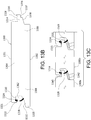
- the decking board 1300 generally includes a top cap coat 1301 and lower cap coat 1302, as similarly disclosed in previous embodiments.
- the decking board 1300 includes a male side or first longitudinal side 1306 of the decking board, a female side or second longitudinal side 1308, and a main body 1304 intermediate to the male side 1306 and second side 1308.
- the decking boards 1300 are configured for interlocking engagement with each other.
- the male side 1306 of the decking board 1300 is configured for cooperative interlocking engagement with the female side 1308 of an associated decking board 1300.
- the male side 1306 generally includes an extension member 1314, which extends generally laterally outward from the male side 1306.
- the extension member 1314 is configured for insertion into the female side 1308 of an associated decking board 1300 in the system 1312.
- the extension member 1314 generally includes a first surface 1326 and an opposing second surface 1336 defining a notch 1337. As shown, the extension member 1314 further includes a generally upwardly projecting first lip 1316 positioned, proximate to the first surface 1326. The extension member 1314 further defines an opening 1338 configured to receive a tongue 1320 from an associated decking board 1300 therein. The configuration of the male side 1306 in combination with the extension member 1314 provides a u-shaped configuration 1340.
- the female side 1308 of the decking board 1300 generally includes a first portion or tongue 1320 and a second portion 1321 including a second lip 1322 or bump.
- the first portion 1320 and second portion 1321 have an opening formed therebetween defining a cavity 1362 configured to receive an extension member 1314 of a male side therein.
- the second lip 1322 extends in a generally downward direction from the second portion 1321 and is configured for snapping and/or interlocking engagement with a first lip 1316 provided by an associated decking board 1300.
- the second portion 1321 further includes a second flexible member 1324, positioned generally adjacent to the second lip 1322, along the inner surface 1330 of the second portion 1321.
- the second flexible member 1324 extends in a generally downward direction from the inner surface 1330 such that when the decking board 1300 is in locking engagement with an associated decking board, the second flexible member 1324 engages the surface 1326 of the extension member 1314.
- the second flexible member 1324 has at least one prong extending generally downward. As shown in FIG. 13C , the second flexible member 1324 may have a two-prong configuration for engagement with the extension member 1314.
- the first prong 1333 of the second flexible member 1324 may form a second seal, and the second prong 1331 of the second flexible member 1324 may form a third seal.
- the second flexible member 1324 can include more than two prongs 1331, 1333. It is further contemplated that multiple second flexible members 1324 can be provided on the inner surface 1330 to provide additional seals with the extension member 1314.
- the tongue 1320 extends generally laterally outward from the female side 1308. As shown, the tongue 1320 has a generally sloped inner surface 1332.
- the female side 1308 of the decking board further includes at least one first flexible member 1328, which extends from the surface 1332 in a generally upward direction.
- the first flexible member 1328 is configured for engagement with an extension member 1314 of an associated decking board 1300
- the first flexible member 1328 can include multiple prongs or members to provide multiple points of engagement with the extension member 1314.
- one or more first flexible members 1328 can be provided on the tongue 1320 to provide multiple seals with the extension member 1314 to further block moisture.
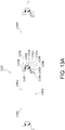
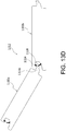
- FIGS. 13A and 13D shows a decking board system 1312 including a first decking board 1300a and a second decking 1300b, configured to be interlocked adjacent to each other.
- the extension member 1314a of decking board 1300a is inserted into cavity 1362b of the decking board 1300b.
- the second flexible member 1324b and first flexible member 1328b cooperatively engage the extension member 1314a.
- the second flexible member 1324b engages the surface 1326a of the extension member 1314a forming a seal
- the first flexible member 1328b engages the notch or recess 1337a.
- the first lip 1316a of the extension member 1314a engages the inner surface 1330b of the decking board 1300b.
- the second lip 1322b of the decking board 1300b engages the inner surface 1326a of the decking board 1300a.
- the tongue 1320b is inserted below the surface 1338a.
- the decking board 1300 provides an opening 1342 for receiving a fastening member or component, such as a bolt or screw. As such, the decking board 1300 may be secured to an adjacent surface. Additionally, FIG. 13C illustrates that when the decking boards are in engagement, channel 1340 is formed between the decking boards 1300a, 1300b to facilitate fluid removal from the decking board surfaces.
Claims (9)
- Bodendiele (1300), umfassend:eine erste Längsseite (1306) mit einem Verlängerungselement (1314, 1314a), wobei das Verlängerungselement (1314, 1314a) eine erste Fläche (1326) und eine gegenüberliegende zweite Fläche (1336) umfasst, wobei die zweite Fläche (1336) eine darin ausgebildete Aussparung (1337, 1337a) aufweist;eine zweite Längsseite (1308) mit einem ersten Abschnitt (1320, 1320b), der eine Zunge ausbildet, und einem zweiten Abschnitt (1321); undeinen mittleren Hauptkörper (1304), der zwischen der ersten Längsseite (1306) und der zweiten Längsseite (1308) angeordnet ist;wobei der erste Abschnitt (1320, 1320b) und der zweite Abschnitt (1321) der zweiten Längsseite (1308) einen Hohlraum (1362, 1362b) dazwischen ausbilden, um ein Verlängerungselement (1314, 1314a) einer zugeordneten Bodendiele (1300) darin aufzunehmen;wobei die Zunge der zweiten Längsseite (1308) ein erstes biegsames Dichtungselement (1328, 1328b) umfasst, das sich von dem ersten Abschnitt (1320, 1320b) allgemein nach oben erstreckt, und der zweite Abschnitt (1321) ein zweites biegsames Dichtungselement (1324, 1324b) umfasst, das sich von dem zweiten Abschnitt (1321) allgemein nach unten erstreckt;wobei das zweite biegsame Dichtungselement (1324, 1324b) konfiguriert ist, um mit einer ersten Fläche (1326) eines zugeordneten Verlängerungselements (1314, 1314a) in Wirkeingriff zu treten, wenn ein Verlängerungselement (1314, 1314a) in den Hohlraum (1362, 1362b) eingesetzt wird;dadurch gekennzeichnet, dass:die erste Fläche (1326) eine erste Lippe (1316, 1316a) umfasst,der zweite Abschnitt (1321) eine zweite Lippe (1322) umfasst unddas zweite biegsame Dichtungselement (1324, 1324b) einen ersten Zinken (1333), der sich von dem zweiten Abschnitt (1321) der zweiten Längsseite (1308) allgemein nach unten erstreckt, und einen zweiten Zinken (1331), der ein drittes biegsames Dichtungselement ausbildet, das sich von dem zweiten Abschnitt (1321) der zweiten Längsseite (1308) allgemein nach unten erstreckt, umfasst.
- Bodendiele (1300) nach Anspruch 1, wobei das erste biegsame Dichtungselement (1328, 1328b) konfiguriert ist, um mit der zweiten Fläche (1336) eines zugeordneten Verlängerungselements (1314, 1314a) in Wirkeingriff zu treten, wenn das zugeordnete Verlängerungselement (1314, 1314a) in den Hohlraum (1362, 1362b) eingesetzt wird.
- Bodendiele (1300) nach Anspruch 1, wobei der erste Abschnitt (1320, 1320b) der zweiten Längsseite (1308) eine darin ausgebildete Öffnung (1342) zur Aufnahme eines Befestigungselements zum Befestigen der Bodendiele (1300) an einer zugeordneten Fläche umfasst.
- Bodendiele (1300) nach einem der Ansprüche 1-3, wobei das erste biegsame Element (1328, 1328b) konfiguriert ist, um mit einer Aussparung (1337, 1337a) einer zugeordneten Bodendiele (1300) in Eingriff zu treten.
- Bodendiele (1300) nach einem der Ansprüche 1-4, wobei der erste Abschnitt (1320, 1320b) der zweiten Längsseite (1308) und das Verlängerungselement (1314, 1314a) der ersten Längsseite (1306) so konfiguriert sind, dass, wenn eine erste Bodendiele (1300a) und eine zweite Bodendiele (1300b) verriegelt sind, zwischen dem ersten Abschnitt (1320, 1320b) der zweiten Bodendiele (1300b) und dem Verlängerungselement (1314, 1314a) der ersten Bodendiele (1300a) ein Kanal (1340) gebildet ist.
- Bodendiele (1300) nach einem der Ansprüche 1-5, wobei die erste Lippe (1316, 1316a) ein nach oben vorspringendes Widerlager ist.
- Bodendiele (1300) nach einem der Ansprüche 1-6, wobei die zweite Lippe (1322) ein nach unten vorspringendes Widerlager ist.
- Bodendiele (1300) nach einem der Ansprüche 1-7, wobei das erste biegsame Dichtungselement (1328, 1328b) mehrere Zinken umfasst, um mehrere Eingriffspunkte mit dem Verlängerungselement (1314, 1314a) vorzusehen.
- Bodendiele (1300) nach Anspruch 4, wobei das erste biegsame Element (1328, 1328b) eine elastische Lasche ist.
Applications Claiming Priority (1)
| Application Number | Priority Date | Filing Date | Title |
|---|---|---|---|
| US14/276,402 US9353533B2 (en) | 2012-02-23 | 2014-05-13 | Deck system components |
Publications (2)
| Publication Number | Publication Date |
|---|---|
| EP2963203A1 EP2963203A1 (de) | 2016-01-06 |
| EP2963203B1 true EP2963203B1 (de) | 2019-11-20 |
Family
ID=53275982
Family Applications (1)
| Application Number | Title | Priority Date | Filing Date |
|---|---|---|---|
| EP15167391.0A Active EP2963203B1 (de) | 2014-05-13 | 2015-05-12 | Verkleidungsplatte |
Country Status (1)
| Country | Link |
|---|---|
| EP (1) | EP2963203B1 (de) |
Cited By (1)
| Publication number | Priority date | Publication date | Assignee | Title |
|---|---|---|---|---|
| RU202407U1 (ru) * | 2020-09-24 | 2021-02-16 | Андрей Витальевич Норкин | Террасная доска |
Families Citing this family (2)
| Publication number | Priority date | Publication date | Assignee | Title |
|---|---|---|---|---|
| US10760283B2 (en) | 2012-02-23 | 2020-09-01 | Admiral Composite Technologies, Inc. | Deck system and components |
| EP3091140B1 (de) * | 2015-05-05 | 2019-07-24 | Admiral Composite Technologies, Inc. | Decksystem und -komponenten |
Citations (3)
| Publication number | Priority date | Publication date | Assignee | Title |
|---|---|---|---|---|
| US20040035077A1 (en) * | 1995-03-07 | 2004-02-26 | Goran Martensson | Flooring panel or wall panel and use thereof |
| WO2006032378A1 (de) * | 2004-09-17 | 2006-03-30 | Hdm Gmbh | Paneel, insbesondere fussbodenpaneel |
| WO2006104436A1 (en) * | 2005-03-30 | 2006-10-05 | Välinge Innovation AB | Mechanical locking system for floor panels and a method to disconnect floor panels |
Family Cites Families (3)
| Publication number | Priority date | Publication date | Assignee | Title |
|---|---|---|---|---|
| AT413228B (de) * | 2002-08-19 | 2005-12-15 | Kaindl M | Verkleidungsplatte |
| SE525622C2 (sv) * | 2002-12-09 | 2005-03-22 | Pergo Europ Ab | Förfarande för installation av paneler med foganordningar, inkapslat medel och lim |
| US9394698B2 (en) * | 2012-02-23 | 2016-07-19 | Admiral Composite Technologies, Inc. | Deck system and components |
-
2015
- 2015-05-12 EP EP15167391.0A patent/EP2963203B1/de active Active
Patent Citations (3)
| Publication number | Priority date | Publication date | Assignee | Title |
|---|---|---|---|---|
| US20040035077A1 (en) * | 1995-03-07 | 2004-02-26 | Goran Martensson | Flooring panel or wall panel and use thereof |
| WO2006032378A1 (de) * | 2004-09-17 | 2006-03-30 | Hdm Gmbh | Paneel, insbesondere fussbodenpaneel |
| WO2006104436A1 (en) * | 2005-03-30 | 2006-10-05 | Välinge Innovation AB | Mechanical locking system for floor panels and a method to disconnect floor panels |
Cited By (1)
| Publication number | Priority date | Publication date | Assignee | Title |
|---|---|---|---|---|
| RU202407U1 (ru) * | 2020-09-24 | 2021-02-16 | Андрей Витальевич Норкин | Террасная доска |
Also Published As
| Publication number | Publication date |
|---|---|
| EP2963203A1 (de) | 2016-01-06 |
Similar Documents
| Publication | Publication Date | Title |
|---|---|---|
| US9394698B2 (en) | Deck system and components | |
| US10760283B2 (en) | Deck system and components | |
| US9353533B2 (en) | Deck system components | |
| CN112912576B (zh) | 多用途砖片系统、砖片覆盖物和砖片 | |
| US9624677B2 (en) | Joint devices, systems, and methods for exterior flooring | |
| US6729097B2 (en) | Hollow building panel having an angled support member and method of making same | |
| US7941989B2 (en) | Deck flashing trim system | |
| US20080209851A1 (en) | Apparatus for Aiding in the Installation and Sealing of Siding | |
| EP2963203B1 (de) | Verkleidungsplatte | |
| CA2395740A1 (en) | Plastic gutter system and components thereof | |
| EP3091140B1 (de) | Decksystem und -komponenten | |
| NZ528974A (en) | Cladding apparatus and methods, typically for roofing, with cladding interengaging with battens | |
| CN105178549A (zh) | 甲板系统和部件 | |
| US8347558B2 (en) | Under deck drainage system and related method | |
| EP2845964B1 (de) | Decksystem und Bodenplatte für ein Decksystem | |
| EP4290032A1 (de) | Paneel und verkleidungssystem | |
| US9109369B2 (en) | Building insulation and siding kit | |
| EA040750B1 (ru) | Многоцелевая плиточная система, плиточное покрытие и плитка | |
| EA042993B1 (ru) | Многоцелевая плиточная система, плиточное покрытие и плитка | |
| FI123865B (fi) | Tiilikaton läpiviennin pellityksen liitoskappale | |
| JP2009114802A (ja) | 床材の敷設方法および床材の敷設方法に用いる床材ズレ防止具 | |
| JP4679471B2 (ja) | 屋根谷部仕上げ具 | |
| JP2001220814A (ja) | バルコニー用床構造体 | |
| CA2712521A1 (en) | Elongated plastic extruded elements to cover an existing boarded surface |
Legal Events
| Date | Code | Title | Description |
|---|---|---|---|
| PUAI | Public reference made under article 153(3) epc to a published international application that has entered the european phase |
Free format text: ORIGINAL CODE: 0009012 |
|
| AK | Designated contracting states |
Kind code of ref document: A1 Designated state(s): AL AT BE BG CH CY CZ DE DK EE ES FI FR GB GR HR HU IE IS IT LI LT LU LV MC MK MT NL NO PL PT RO RS SE SI SK SM TR |
|
| AX | Request for extension of the european patent |
Extension state: BA ME |
|
| RAP1 | Party data changed (applicant data changed or rights of an application transferred) |
Owner name: ADMIRAL COMPOSITE TECHNOLOGIES, INC. |
|
| RIN1 | Information on inventor provided before grant (corrected) |
Inventor name: CARRUBBA, VINCENT FRANK |
|
| 17P | Request for examination filed |
Effective date: 20160705 |
|
| RBV | Designated contracting states (corrected) |
Designated state(s): AL AT BE BG CH CY CZ DE DK EE ES FI FR GB GR HR HU IE IS IT LI LT LU LV MC MK MT NL NO PL PT RO RS SE SI SK SM TR |
|
| STAA | Information on the status of an ep patent application or granted ep patent |
Free format text: STATUS: EXAMINATION IS IN PROGRESS |
|
| 17Q | First examination report despatched |
Effective date: 20171107 |
|
| GRAP | Despatch of communication of intention to grant a patent |
Free format text: ORIGINAL CODE: EPIDOSNIGR1 |
|
| STAA | Information on the status of an ep patent application or granted ep patent |
Free format text: STATUS: GRANT OF PATENT IS INTENDED |
|
| INTG | Intention to grant announced |
Effective date: 20190318 |
|
| GRAS | Grant fee paid |
Free format text: ORIGINAL CODE: EPIDOSNIGR3 |
|
| GRAA | (expected) grant |
Free format text: ORIGINAL CODE: 0009210 |
|
| STAA | Information on the status of an ep patent application or granted ep patent |
Free format text: STATUS: THE PATENT HAS BEEN GRANTED |
|
| AK | Designated contracting states |
Kind code of ref document: B1 Designated state(s): AL AT BE BG CH CY CZ DE DK EE ES FI FR GB GR HR HU IE IS IT LI LT LU LV MC MK MT NL NO PL PT RO RS SE SI SK SM TR |
|
| REG | Reference to a national code |
Ref country code: GB Ref legal event code: FG4D |
|
| REG | Reference to a national code |
Ref country code: CH Ref legal event code: EP |
|
| REG | Reference to a national code |
Ref country code: DE Ref legal event code: R096 Ref document number: 602015041913 Country of ref document: DE |
|
| REG | Reference to a national code |
Ref country code: IE Ref legal event code: FG4D |
|
| REG | Reference to a national code |
Ref country code: AT Ref legal event code: REF Ref document number: 1204349 Country of ref document: AT Kind code of ref document: T Effective date: 20191215 |
|
| REG | Reference to a national code |
Ref country code: NL Ref legal event code: MP Effective date: 20191120 |
|
| REG | Reference to a national code |
Ref country code: LT Ref legal event code: MG4D |
|
| PG25 | Lapsed in a contracting state [announced via postgrant information from national office to epo] |
Ref country code: BG Free format text: LAPSE BECAUSE OF FAILURE TO SUBMIT A TRANSLATION OF THE DESCRIPTION OR TO PAY THE FEE WITHIN THE PRESCRIBED TIME-LIMIT Effective date: 20200220 Ref country code: FI Free format text: LAPSE BECAUSE OF FAILURE TO SUBMIT A TRANSLATION OF THE DESCRIPTION OR TO PAY THE FEE WITHIN THE PRESCRIBED TIME-LIMIT Effective date: 20191120 Ref country code: LT Free format text: LAPSE BECAUSE OF FAILURE TO SUBMIT A TRANSLATION OF THE DESCRIPTION OR TO PAY THE FEE WITHIN THE PRESCRIBED TIME-LIMIT Effective date: 20191120 Ref country code: GR Free format text: LAPSE BECAUSE OF FAILURE TO SUBMIT A TRANSLATION OF THE DESCRIPTION OR TO PAY THE FEE WITHIN THE PRESCRIBED TIME-LIMIT Effective date: 20200221 Ref country code: NO Free format text: LAPSE BECAUSE OF FAILURE TO SUBMIT A TRANSLATION OF THE DESCRIPTION OR TO PAY THE FEE WITHIN THE PRESCRIBED TIME-LIMIT Effective date: 20200220 Ref country code: SE Free format text: LAPSE BECAUSE OF FAILURE TO SUBMIT A TRANSLATION OF THE DESCRIPTION OR TO PAY THE FEE WITHIN THE PRESCRIBED TIME-LIMIT Effective date: 20191120 Ref country code: LV Free format text: LAPSE BECAUSE OF FAILURE TO SUBMIT A TRANSLATION OF THE DESCRIPTION OR TO PAY THE FEE WITHIN THE PRESCRIBED TIME-LIMIT Effective date: 20191120 Ref country code: NL Free format text: LAPSE BECAUSE OF FAILURE TO SUBMIT A TRANSLATION OF THE DESCRIPTION OR TO PAY THE FEE WITHIN THE PRESCRIBED TIME-LIMIT Effective date: 20191120 |
|
| PG25 | Lapsed in a contracting state [announced via postgrant information from national office to epo] |
Ref country code: HR Free format text: LAPSE BECAUSE OF FAILURE TO SUBMIT A TRANSLATION OF THE DESCRIPTION OR TO PAY THE FEE WITHIN THE PRESCRIBED TIME-LIMIT Effective date: 20191120 Ref country code: RS Free format text: LAPSE BECAUSE OF FAILURE TO SUBMIT A TRANSLATION OF THE DESCRIPTION OR TO PAY THE FEE WITHIN THE PRESCRIBED TIME-LIMIT Effective date: 20191120 Ref country code: IS Free format text: LAPSE BECAUSE OF FAILURE TO SUBMIT A TRANSLATION OF THE DESCRIPTION OR TO PAY THE FEE WITHIN THE PRESCRIBED TIME-LIMIT Effective date: 20200320 |
|
| PG25 | Lapsed in a contracting state [announced via postgrant information from national office to epo] |
Ref country code: AL Free format text: LAPSE BECAUSE OF FAILURE TO SUBMIT A TRANSLATION OF THE DESCRIPTION OR TO PAY THE FEE WITHIN THE PRESCRIBED TIME-LIMIT Effective date: 20191120 |
|
| PG25 | Lapsed in a contracting state [announced via postgrant information from national office to epo] |
Ref country code: PT Free format text: LAPSE BECAUSE OF FAILURE TO SUBMIT A TRANSLATION OF THE DESCRIPTION OR TO PAY THE FEE WITHIN THE PRESCRIBED TIME-LIMIT Effective date: 20200412 Ref country code: EE Free format text: LAPSE BECAUSE OF FAILURE TO SUBMIT A TRANSLATION OF THE DESCRIPTION OR TO PAY THE FEE WITHIN THE PRESCRIBED TIME-LIMIT Effective date: 20191120 Ref country code: DK Free format text: LAPSE BECAUSE OF FAILURE TO SUBMIT A TRANSLATION OF THE DESCRIPTION OR TO PAY THE FEE WITHIN THE PRESCRIBED TIME-LIMIT Effective date: 20191120 Ref country code: RO Free format text: LAPSE BECAUSE OF FAILURE TO SUBMIT A TRANSLATION OF THE DESCRIPTION OR TO PAY THE FEE WITHIN THE PRESCRIBED TIME-LIMIT Effective date: 20191120 Ref country code: CZ Free format text: LAPSE BECAUSE OF FAILURE TO SUBMIT A TRANSLATION OF THE DESCRIPTION OR TO PAY THE FEE WITHIN THE PRESCRIBED TIME-LIMIT Effective date: 20191120 Ref country code: ES Free format text: LAPSE BECAUSE OF FAILURE TO SUBMIT A TRANSLATION OF THE DESCRIPTION OR TO PAY THE FEE WITHIN THE PRESCRIBED TIME-LIMIT Effective date: 20191120 |
|
| REG | Reference to a national code |
Ref country code: AT Ref legal event code: MK05 Ref document number: 1204349 Country of ref document: AT Kind code of ref document: T Effective date: 20191120 |
|
| REG | Reference to a national code |
Ref country code: DE Ref legal event code: R097 Ref document number: 602015041913 Country of ref document: DE |
|
| PG25 | Lapsed in a contracting state [announced via postgrant information from national office to epo] |
Ref country code: SM Free format text: LAPSE BECAUSE OF FAILURE TO SUBMIT A TRANSLATION OF THE DESCRIPTION OR TO PAY THE FEE WITHIN THE PRESCRIBED TIME-LIMIT Effective date: 20191120 Ref country code: SK Free format text: LAPSE BECAUSE OF FAILURE TO SUBMIT A TRANSLATION OF THE DESCRIPTION OR TO PAY THE FEE WITHIN THE PRESCRIBED TIME-LIMIT Effective date: 20191120 |
|
| PLBE | No opposition filed within time limit |
Free format text: ORIGINAL CODE: 0009261 |
|
| STAA | Information on the status of an ep patent application or granted ep patent |
Free format text: STATUS: NO OPPOSITION FILED WITHIN TIME LIMIT |
|
| 26N | No opposition filed |
Effective date: 20200821 |
|
| PG25 | Lapsed in a contracting state [announced via postgrant information from national office to epo] |
Ref country code: PL Free format text: LAPSE BECAUSE OF FAILURE TO SUBMIT A TRANSLATION OF THE DESCRIPTION OR TO PAY THE FEE WITHIN THE PRESCRIBED TIME-LIMIT Effective date: 20191120 Ref country code: AT Free format text: LAPSE BECAUSE OF FAILURE TO SUBMIT A TRANSLATION OF THE DESCRIPTION OR TO PAY THE FEE WITHIN THE PRESCRIBED TIME-LIMIT Effective date: 20191120 Ref country code: SI Free format text: LAPSE BECAUSE OF FAILURE TO SUBMIT A TRANSLATION OF THE DESCRIPTION OR TO PAY THE FEE WITHIN THE PRESCRIBED TIME-LIMIT Effective date: 20191120 |
|
| PG25 | Lapsed in a contracting state [announced via postgrant information from national office to epo] |
Ref country code: MC Free format text: LAPSE BECAUSE OF FAILURE TO SUBMIT A TRANSLATION OF THE DESCRIPTION OR TO PAY THE FEE WITHIN THE PRESCRIBED TIME-LIMIT Effective date: 20191120 Ref country code: LI Free format text: LAPSE BECAUSE OF NON-PAYMENT OF DUE FEES Effective date: 20200531 Ref country code: CH Free format text: LAPSE BECAUSE OF NON-PAYMENT OF DUE FEES Effective date: 20200531 Ref country code: IT Free format text: LAPSE BECAUSE OF FAILURE TO SUBMIT A TRANSLATION OF THE DESCRIPTION OR TO PAY THE FEE WITHIN THE PRESCRIBED TIME-LIMIT Effective date: 20191120 |
|
| REG | Reference to a national code |
Ref country code: BE Ref legal event code: MM Effective date: 20200531 |
|
| PG25 | Lapsed in a contracting state [announced via postgrant information from national office to epo] |
Ref country code: LU Free format text: LAPSE BECAUSE OF NON-PAYMENT OF DUE FEES Effective date: 20200512 |
|
| PG25 | Lapsed in a contracting state [announced via postgrant information from national office to epo] |
Ref country code: FR Free format text: LAPSE BECAUSE OF NON-PAYMENT OF DUE FEES Effective date: 20200531 Ref country code: IE Free format text: LAPSE BECAUSE OF NON-PAYMENT OF DUE FEES Effective date: 20200512 |
|
| PG25 | Lapsed in a contracting state [announced via postgrant information from national office to epo] |
Ref country code: BE Free format text: LAPSE BECAUSE OF NON-PAYMENT OF DUE FEES Effective date: 20200531 |
|
| PG25 | Lapsed in a contracting state [announced via postgrant information from national office to epo] |
Ref country code: TR Free format text: LAPSE BECAUSE OF FAILURE TO SUBMIT A TRANSLATION OF THE DESCRIPTION OR TO PAY THE FEE WITHIN THE PRESCRIBED TIME-LIMIT Effective date: 20191120 Ref country code: MT Free format text: LAPSE BECAUSE OF FAILURE TO SUBMIT A TRANSLATION OF THE DESCRIPTION OR TO PAY THE FEE WITHIN THE PRESCRIBED TIME-LIMIT Effective date: 20191120 Ref country code: CY Free format text: LAPSE BECAUSE OF FAILURE TO SUBMIT A TRANSLATION OF THE DESCRIPTION OR TO PAY THE FEE WITHIN THE PRESCRIBED TIME-LIMIT Effective date: 20191120 |
|
| PG25 | Lapsed in a contracting state [announced via postgrant information from national office to epo] |
Ref country code: MK Free format text: LAPSE BECAUSE OF FAILURE TO SUBMIT A TRANSLATION OF THE DESCRIPTION OR TO PAY THE FEE WITHIN THE PRESCRIBED TIME-LIMIT Effective date: 20191120 |
|
| PGFP | Annual fee paid to national office [announced via postgrant information from national office to epo] |
Ref country code: GB Payment date: 20230727 Year of fee payment: 9 |
|
| PGFP | Annual fee paid to national office [announced via postgrant information from national office to epo] |
Ref country code: DE Payment date: 20230727 Year of fee payment: 9 |