EP2963150A1 - Film formation device and film formation method - Google Patents
Film formation device and film formation method Download PDFInfo
- Publication number
- EP2963150A1 EP2963150A1 EP14756496.7A EP14756496A EP2963150A1 EP 2963150 A1 EP2963150 A1 EP 2963150A1 EP 14756496 A EP14756496 A EP 14756496A EP 2963150 A1 EP2963150 A1 EP 2963150A1
- Authority
- EP
- European Patent Office
- Prior art keywords
- layer
- forming
- plasma
- film
- space
- Prior art date
- Legal status (The legal status is an assumption and is not a legal conclusion. Google has not performed a legal analysis and makes no representation as to the accuracy of the status listed.)
- Granted
Links
- 238000000034 method Methods 0.000 title claims description 35
- 230000015572 biosynthetic process Effects 0.000 title abstract 3
- 239000000758 substrate Substances 0.000 claims abstract description 78
- 238000000638 solvent extraction Methods 0.000 claims abstract description 64
- 230000037361 pathway Effects 0.000 claims abstract description 34
- 230000007246 mechanism Effects 0.000 claims abstract description 18
- 230000008569 process Effects 0.000 claims description 12
- 238000004804 winding Methods 0.000 claims description 10
- 238000006243 chemical reaction Methods 0.000 claims description 8
- 238000000151 deposition Methods 0.000 claims description 8
- 230000008021 deposition Effects 0.000 claims description 6
- 150000002500 ions Chemical class 0.000 abstract 1
- 239000007789 gas Substances 0.000 description 173
- 239000010410 layer Substances 0.000 description 61
- 239000011261 inert gas Substances 0.000 description 32
- 238000000231 atomic layer deposition Methods 0.000 description 16
- 238000010926 purge Methods 0.000 description 6
- XKRFYHLGVUSROY-UHFFFAOYSA-N Argon Chemical compound [Ar] XKRFYHLGVUSROY-UHFFFAOYSA-N 0.000 description 4
- 239000002243 precursor Substances 0.000 description 3
- 238000003860 storage Methods 0.000 description 3
- IJGRMHOSHXDMSA-UHFFFAOYSA-N Atomic nitrogen Chemical compound N#N IJGRMHOSHXDMSA-UHFFFAOYSA-N 0.000 description 2
- 229910052786 argon Inorganic materials 0.000 description 2
- 229910001873 dinitrogen Inorganic materials 0.000 description 2
- 230000000694 effects Effects 0.000 description 2
- 239000001307 helium Substances 0.000 description 2
- 229910052734 helium Inorganic materials 0.000 description 2
- SWQJXJOGLNCZEY-UHFFFAOYSA-N helium atom Chemical compound [He] SWQJXJOGLNCZEY-UHFFFAOYSA-N 0.000 description 2
- 239000012212 insulator Substances 0.000 description 2
- 238000004519 manufacturing process Methods 0.000 description 2
- 239000000463 material Substances 0.000 description 2
- 229910052754 neon Inorganic materials 0.000 description 2
- GKAOGPIIYCISHV-UHFFFAOYSA-N neon atom Chemical compound [Ne] GKAOGPIIYCISHV-UHFFFAOYSA-N 0.000 description 2
- JLTRXTDYQLMHGR-UHFFFAOYSA-N trimethylaluminium Chemical compound C[Al](C)C JLTRXTDYQLMHGR-UHFFFAOYSA-N 0.000 description 2
- WQKWNXSKQLVRHK-UHFFFAOYSA-N CC[Hf](C)N Chemical compound CC[Hf](C)N WQKWNXSKQLVRHK-UHFFFAOYSA-N 0.000 description 1
- JNCHUTSLSYTQEJ-UHFFFAOYSA-N CC[Zr](C)N Chemical compound CC[Zr](C)N JNCHUTSLSYTQEJ-UHFFFAOYSA-N 0.000 description 1
- 230000009471 action Effects 0.000 description 1
- 230000004888 barrier function Effects 0.000 description 1
- 239000000919 ceramic Substances 0.000 description 1
- 230000001419 dependent effect Effects 0.000 description 1
- 239000011521 glass Substances 0.000 description 1
- 238000009616 inductively coupled plasma Methods 0.000 description 1
- 238000002347 injection Methods 0.000 description 1
- 239000007924 injection Substances 0.000 description 1
- 230000004048 modification Effects 0.000 description 1
- 238000012986 modification Methods 0.000 description 1
- 230000007935 neutral effect Effects 0.000 description 1
- 239000011347 resin Substances 0.000 description 1
- 229920005989 resin Polymers 0.000 description 1
- 230000000717 retained effect Effects 0.000 description 1
- FZHAPNGMFPVSLP-UHFFFAOYSA-N silanamine Chemical compound [SiH3]N FZHAPNGMFPVSLP-UHFFFAOYSA-N 0.000 description 1
- 239000000243 solution Substances 0.000 description 1
- 239000000126 substance Substances 0.000 description 1
- 239000002344 surface layer Substances 0.000 description 1
- 230000008719 thickening Effects 0.000 description 1
Images
Classifications
-
- C—CHEMISTRY; METALLURGY
- C23—COATING METALLIC MATERIAL; COATING MATERIAL WITH METALLIC MATERIAL; CHEMICAL SURFACE TREATMENT; DIFFUSION TREATMENT OF METALLIC MATERIAL; COATING BY VACUUM EVAPORATION, BY SPUTTERING, BY ION IMPLANTATION OR BY CHEMICAL VAPOUR DEPOSITION, IN GENERAL; INHIBITING CORROSION OF METALLIC MATERIAL OR INCRUSTATION IN GENERAL
- C23C—COATING METALLIC MATERIAL; COATING MATERIAL WITH METALLIC MATERIAL; SURFACE TREATMENT OF METALLIC MATERIAL BY DIFFUSION INTO THE SURFACE, BY CHEMICAL CONVERSION OR SUBSTITUTION; COATING BY VACUUM EVAPORATION, BY SPUTTERING, BY ION IMPLANTATION OR BY CHEMICAL VAPOUR DEPOSITION, IN GENERAL
- C23C16/00—Chemical coating by decomposition of gaseous compounds, without leaving reaction products of surface material in the coating, i.e. chemical vapour deposition [CVD] processes
- C23C16/44—Chemical coating by decomposition of gaseous compounds, without leaving reaction products of surface material in the coating, i.e. chemical vapour deposition [CVD] processes characterised by the method of coating
- C23C16/455—Chemical coating by decomposition of gaseous compounds, without leaving reaction products of surface material in the coating, i.e. chemical vapour deposition [CVD] processes characterised by the method of coating characterised by the method used for introducing gases into reaction chamber or for modifying gas flows in reaction chamber
- C23C16/45523—Pulsed gas flow or change of composition over time
- C23C16/45525—Atomic layer deposition [ALD]
- C23C16/45544—Atomic layer deposition [ALD] characterized by the apparatus
-
- C—CHEMISTRY; METALLURGY
- C23—COATING METALLIC MATERIAL; COATING MATERIAL WITH METALLIC MATERIAL; CHEMICAL SURFACE TREATMENT; DIFFUSION TREATMENT OF METALLIC MATERIAL; COATING BY VACUUM EVAPORATION, BY SPUTTERING, BY ION IMPLANTATION OR BY CHEMICAL VAPOUR DEPOSITION, IN GENERAL; INHIBITING CORROSION OF METALLIC MATERIAL OR INCRUSTATION IN GENERAL
- C23C—COATING METALLIC MATERIAL; COATING MATERIAL WITH METALLIC MATERIAL; SURFACE TREATMENT OF METALLIC MATERIAL BY DIFFUSION INTO THE SURFACE, BY CHEMICAL CONVERSION OR SUBSTITUTION; COATING BY VACUUM EVAPORATION, BY SPUTTERING, BY ION IMPLANTATION OR BY CHEMICAL VAPOUR DEPOSITION, IN GENERAL
- C23C16/00—Chemical coating by decomposition of gaseous compounds, without leaving reaction products of surface material in the coating, i.e. chemical vapour deposition [CVD] processes
- C23C16/44—Chemical coating by decomposition of gaseous compounds, without leaving reaction products of surface material in the coating, i.e. chemical vapour deposition [CVD] processes characterised by the method of coating
- C23C16/455—Chemical coating by decomposition of gaseous compounds, without leaving reaction products of surface material in the coating, i.e. chemical vapour deposition [CVD] processes characterised by the method of coating characterised by the method used for introducing gases into reaction chamber or for modifying gas flows in reaction chamber
- C23C16/45523—Pulsed gas flow or change of composition over time
- C23C16/45525—Atomic layer deposition [ALD]
- C23C16/45527—Atomic layer deposition [ALD] characterized by the ALD cycle, e.g. different flows or temperatures during half-reactions, unusual pulsing sequence, use of precursor mixtures or auxiliary reactants or activations
- C23C16/45536—Use of plasma, radiation or electromagnetic fields
-
- C—CHEMISTRY; METALLURGY
- C23—COATING METALLIC MATERIAL; COATING MATERIAL WITH METALLIC MATERIAL; CHEMICAL SURFACE TREATMENT; DIFFUSION TREATMENT OF METALLIC MATERIAL; COATING BY VACUUM EVAPORATION, BY SPUTTERING, BY ION IMPLANTATION OR BY CHEMICAL VAPOUR DEPOSITION, IN GENERAL; INHIBITING CORROSION OF METALLIC MATERIAL OR INCRUSTATION IN GENERAL
- C23C—COATING METALLIC MATERIAL; COATING MATERIAL WITH METALLIC MATERIAL; SURFACE TREATMENT OF METALLIC MATERIAL BY DIFFUSION INTO THE SURFACE, BY CHEMICAL CONVERSION OR SUBSTITUTION; COATING BY VACUUM EVAPORATION, BY SPUTTERING, BY ION IMPLANTATION OR BY CHEMICAL VAPOUR DEPOSITION, IN GENERAL
- C23C16/00—Chemical coating by decomposition of gaseous compounds, without leaving reaction products of surface material in the coating, i.e. chemical vapour deposition [CVD] processes
- C23C16/44—Chemical coating by decomposition of gaseous compounds, without leaving reaction products of surface material in the coating, i.e. chemical vapour deposition [CVD] processes characterised by the method of coating
- C23C16/54—Apparatus specially adapted for continuous coating
- C23C16/545—Apparatus specially adapted for continuous coating for coating elongated substrates
-
- H—ELECTRICITY
- H01—ELECTRIC ELEMENTS
- H01J—ELECTRIC DISCHARGE TUBES OR DISCHARGE LAMPS
- H01J37/00—Discharge tubes with provision for introducing objects or material to be exposed to the discharge, e.g. for the purpose of examination or processing thereof
- H01J37/32—Gas-filled discharge tubes
- H01J37/32009—Arrangements for generation of plasma specially adapted for examination or treatment of objects, e.g. plasma sources
- H01J37/32082—Radio frequency generated discharge
- H01J37/32091—Radio frequency generated discharge the radio frequency energy being capacitively coupled to the plasma
-
- H—ELECTRICITY
- H01—ELECTRIC ELEMENTS
- H01J—ELECTRIC DISCHARGE TUBES OR DISCHARGE LAMPS
- H01J37/00—Discharge tubes with provision for introducing objects or material to be exposed to the discharge, e.g. for the purpose of examination or processing thereof
- H01J37/32—Gas-filled discharge tubes
- H01J37/32009—Arrangements for generation of plasma specially adapted for examination or treatment of objects, e.g. plasma sources
- H01J37/32422—Arrangement for selecting ions or species in the plasma
-
- H—ELECTRICITY
- H01—ELECTRIC ELEMENTS
- H01J—ELECTRIC DISCHARGE TUBES OR DISCHARGE LAMPS
- H01J37/00—Discharge tubes with provision for introducing objects or material to be exposed to the discharge, e.g. for the purpose of examination or processing thereof
- H01J37/32—Gas-filled discharge tubes
- H01J37/32431—Constructional details of the reactor
- H01J37/32733—Means for moving the material to be treated
- H01J37/32752—Means for moving the material to be treated for moving the material across the discharge
- H01J37/32761—Continuous moving
-
- C—CHEMISTRY; METALLURGY
- C03—GLASS; MINERAL OR SLAG WOOL
- C03C—CHEMICAL COMPOSITION OF GLASSES, GLAZES OR VITREOUS ENAMELS; SURFACE TREATMENT OF GLASS; SURFACE TREATMENT OF FIBRES OR FILAMENTS MADE FROM GLASS, MINERALS OR SLAGS; JOINING GLASS TO GLASS OR OTHER MATERIALS
- C03C2218/00—Methods for coating glass
- C03C2218/10—Deposition methods
- C03C2218/15—Deposition methods from the vapour phase
- C03C2218/152—Deposition methods from the vapour phase by cvd
- C03C2218/153—Deposition methods from the vapour phase by cvd by plasma-enhanced cvd
Definitions
- a present disclosure relates to a layer-forming device that forms a thin layer in atomic layer unit using a layer-forming gas and a reactive gas, and a layer-forming method.
- ALD Atomic Layer Deposition
- a thin layer configuration having a plurality of stacked layers in atomic layer unit is formed by alternatively supplying a layer-forming gas and a reactive gas as a precursor gases. Because a thin layer obtained by the ALD is able to produce an extremely thin layer thickness of approximately 0.1 nm, the ALD may be effectively utilized as a highly precise layer-forming process in the production of various devices.
- a layer-forming device that allows for production costs to be reduced and for flexibility to be enhanced during a layer-forming process (see, Patent Literature 1).
- the abovementioned layer-forming device includes: a feeding mechanism that feeds a base material as a body on which a layer is formed, and the feeding mechanism includes a plurality of roller members; and a plurality of head parts that are disposed so as to face the roller member, and plurality of head parts act as a gas source capable of locally outputting a precursor gas for performing atomic layer deposition to the base material.
- each head part is constructed to allow a separate output of a plurality of types of precursor gases.
- Patent Literature 1 JP-A 2011-137208
- a layer-forming device employs a flexible substrate, film-shaped substrate, or sheet-shaped substrate.
- the layer-forming device alternately supplies different gases to the substrate by controlling the substrate to pass by a plurality of head parts while feeding the substrate via a guide roller.
- the layer-forming device forms a thin layer in atomic layer unit by alternately supplying different gases to the substrate, and by reacting a supplied gas and a layer of a layer-forming component formed on the substrate of another gas that has been supplied.
- the reaction is temperature dependent. Therefore, it is necessary to increase a temperature of the substrate in order to speed up the reaction. But, in a case where using a flexible resin-type film as the substrate, the substrate can only be raised from a heat-resistant temperature thereof up to 80 to 100°C (only a low-temperature process may be performed).
- a layer-forming process is known in ALD using plasma (hereinafter referred to as "plasma ALD") that allows for layer-forming at a low substrate temperature (80 to 100°C) to the same degree as layer-forming at a high substrate temperature (300 to 400°C).
- plasma ALD plasma
- a highly reactive radical atom, radical molecule, or ion generated from plasma is employed. Accordingly, wherever possible, a combination of any layer-forming gas with the reactive radical atom, the radical molecule, or the ion in a space should be avoided.
- An objective of the present disclosure is to provide a layer-forming device forming layer on the substrate during feeding using plasma ALD that allows for layer-forming to be more efficiently conducted, and also to provide a layer-forming device forming layer on the substrate during feeding using plasma ALD that may achieve a simplified plasma ALD configuration and a layer-forming method using the layer-forming device.
- a layer-forming device that forms a thin layer in atomic layer unit using a layer-forming gas and a reactive gas.
- the layer-forming device includes:
- an opposing surface of the space-partitioning wall that faces the plasma-generating electrode is composed of a grounding electrode.
- Each of the gas injectors is preferably disposed on a surface of the space-partitioning wall opposite to an opposing surface of the space-partitioning wall that faces the plasma-generating electrode.
- a gas supply hole for supplying the reactive gas inside the plasma-generating space is preferably disposed in a side wall of the layer-forming container.
- a dummy injector configured not to supply the layer-forming gas to the substrate is preferably disposed further on a downstream side of the feeding direction than a furthest downstream gas injector positioned at a furthest downstream side of the feeding direction of the substrate, and the dummy injector is disposed so as to be spaced at an interval away from the furthest downstream gas injector, such that a furthest downstream through hole positioned on a furthest downstream side of the feeding direction of the plurality of through holes is positioned between the dummy injector and the furthest downstream injector.
- the feeding mechanism preferably includes a pair of rotary rollers, the substrate is a long flexible film, and the film is wound onto one rotary roller before feeding.
- Each rotary roller is preferably configured to rotate in different directions.
- a layer-forming method that employs a layer-forming device.
- the layer-forming device includes:
- each set of sub-processes including :
- a layer-forming device and a layer-forming method allow for layer-forming to be more efficiently conducted, and for a simplified ALD configuration to be achieved.
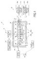
- FIG. 1 illustrates a schematic drawing of a layer-forming device of a present embodiment.
- a layer-forming device 10 is a device that forms a thin layer in atomic layer unit using a layer-forming gas and a reactive gas.
- the layer-forming device 10 includes: a layer-forming container 12; a feeding mechanism 14; a plasma-generating unit 16; a space-partitioning wall 17; an injector unit 18; a gas supply unit 20; and an exhaust unit 22.
- the layer-forming device 10 has the below-mentioned configuration.
- the feeding mechanism 14 feeds a substrate for layer-forming inside the layer-forming container 12.
- the plasma-generating unit 16 includes plasma-generating electrode.
- the plasma-generating electrode in the layer-forming container 12 is disposed so as to face a feeding pathway of the substrate during feeding.
- the plasma-generating electrode generates plasma by using a reactive gas inside a layer-forming space as a result of a supply of electric power received.
- the space-partitioning wall 17 in the layer-forming container 12 is disposed between the feeding pathway of the substrate and the plasma-generating electrode, and the space-partitioning wall 17 forms a plasma-generating space between plasma-generating electrode and the space-partitioning wall 17.
- the space-partitioning wall has a plurality of slit-shaped through holes, which communicate the plasma generating space and a space between the feeding pathway of the substrate and the plasma-generating electrode, disposed at intervals along a feeding direction of the substrate. A radical or an ion generated from the plasma or a part of the plasma may pass through the though holes.
- the injector unit 18 includes a plurality of gas injectors (hereinafter, simply referred to as "injector"). Each injector outputs a layer-forming gas from a layer-forming gas supply opening, and supplies the layer-forming gas to the substrate. Each injector is disposed between the space-partitioning wall 17 and the feeding pathway, and sandwiched by adjacent through holes of the though holes in the space-partitioning wall 17 from both sides of the feeding direction of the substrate.
- the present embodiment describes an extremely thin glass plate or resin film as the substrate for layer-formation.
- the present embodiment employs a long flexible substrate that can be wound into a rolled shape as a substrate for layer-formation.
- the substrate employed in the present embodiment is not limited to a flexible substrate.
- a one-piece unflexible plate-shaped substrate may be used as the substrate for layer-formation.
- the feeding mechanism 14, a plasma-generating electrode 16a associated with the plasma-generating unit 16, and the injector unit 18, are mainly disposed within the layer-forming space in the layer-forming container 12.
- the layer-forming container 12 is for layer-formation on the substrate inside the layer-forming space by maintaining the layer-forming space at a predetermined pressure or at a reduced pressure.
- a thermal heater 24 for setting ambient atmosphere inside the layer-forming space to a desired temperature during the layer-forming is disposed in each wall surface of an outer periphery of the container 12.
- the substrate for layer-formation that is fed by the feeding mechanism 14 is a flexible film F from a roll of film (a roll wound onto a rotary roller 14a or a rotary roller 14b).
- the feeding mechanism 14 includes the rotary rollers 14a, 14b and feeds the film F inside the layer-forming container 12.
- the rotary rollers 14a, 14b are connected to a drive motor (not shown).
- the rotary rollers 14a, 14b are configured to rotate by rotation of the drive motor. The rotational direction of the drive motor can be selected.
- the film F is wound onto the rotary rollers 14a, 14b before being fed.
- the film F is formed in a roll shape.
- one of the rotary rollers 14a, 14b operates as a winding roller and the other one of the rotary rollers 14a, 14b as a feeding roller.
- the film F is unwound from being wound in a roll (rotary roller 14b) by the rotation of the rotary roller 14a, 14b, and the film F is wound onto the rotary roller 14a.
- the unwound film F is fed in one direction for layer-forming process, then the film F subjected to layer-forming process during feeding is wound onto the rotary roller 14a, thereby producing a roll of processed film.
- FIG. 1 illustrates the film F being fed from the rotary roller 14b to rotary roller 14a, and the film F being wound by the rotary roller 14a.
- the layer-formation on the film F is repeated in order to thicken a layer thickness of a formed thin layer on the film F.
- the feeding mechanism 14 feeds from the rotary roller 14a towards the rotary roller 14b, i.e., in a direction opposing the feeding direction during the previous layer-forming process, by again unwinding the roll of processed film obtained by winding of the processed film F onto the rotary roller 14a after layer-forming process.
- the film F has the layer thickened.
- the rotary roller 14b winds the processed film F to make a new roll of processed film.
- the feeding mechanism 14 feeds the film F from the rotary roller 14b towards the rotary roller 14a, i.e., in a direction opposing the feeding direction during the previous layer-forming process, in order to further thicken the layer thickness.
- a layer thickness becomes thickened.
- the rotary roller 14a winds the processed film F to make a new roll of processed film. Accordingly, it is preferable that a target layer thickness is obtained on film F by thickening the layer thickness of the thin layer while repeating the feeding of the film F towards different directions.
- each of the rotary rollers 14a, 14b has a configuration such that each can rotate in different directions. Therefore, the feeding direction of the film F is freely selectable in two different directions.
- the exhaust unit 22 includes exhaust devices 22a, 22b such as a rotary pump or a dry pump.
- the exhaust unit 22 maintains a constant pressure by exhausting the gas inside the plasma-generating space where plasma is generated and by exhausting the gas inside the layer-forming space inside the container 12.
- the exhaust device 22a exhausts the reactive gas inside the below-mentioned plasma-generating space.
- the exhaust device 22b exhausts the gas inside the layer-forming space that includes the plasma-generating space below the plasma-generating electrode 16a.
- the plasma-generating unit 16 includes: the plasma-generating electrode 16a; a grounding electrode 16b; a matching box 16c; and a high frequency electric power source 16d.
- the plasma-generating unit 16 generates a reactive substance that reacts with the layer-forming component adsorbed on the film F of the layer-forming gas.
- the space-partitioning wall 17 is disposed inside the layer-forming container 24 so as traverse the layer-forming container 24.
- the space-partitioning wall 17 is disposed between the feeding pathway of the film F and the plasma-generating electrode 16a.
- the plasma-generating electrode 16a in the film-forming container 12 is a plate-shaped electrode.
- the plasma-generating electrode 16a is disposed above the feeding pathway of the film F so as to face towards the feeding pathway along the feeding pathway of the film F.
- the plasma-generating electrode 16a be disposed in parallel to the feeding pathway.
- the plasma-generating electrode 16a generates plasma using the reactive gas inside the film-forming space as a result of the electric power supply received thereto.
- electric supply lines are used to connect the plasma-generating electrode 16a to the high frequency electric power source 16d through a ceiling surface of the layer-forming container 12 via the matching box 16c.
- the high frequency electric power source 16d supplies a high frequency electric voltage to the plasma-generating electrode, e.g., a voltage of 13.56 MHz.
- the grounding electrode 16b is disposed on a surface of the space-partitioning wall 17 so as to face the plasma-generating electrode 16a.
- the opposing surface that faces the plasma-generating electrode 16a of the space-partitioning wall 17 is composed of the grounding electrode 16b.
- the plasma P is generated using the reactive gas supplied to the space between the plasma-generating electrode 16a and the grounding electrode 16b, by applying high frequency voltage to the plasma-generating electrode 16a.
- the space between the plasma-generating electrode 16a and the grounding electrode 16b is the plasma-generating space.
- the present embodiment can employ an inductively coupled plasma method or a conventional plasma-generating method, in addition to a capacitively coupled plasma method that generates plasma between electrodes, in which the plasma-generating electrode 16a and the grounding electrode 16b are disposed to face each other.
- the electric supply lines that supply the high frequency electric power to the high frequency electric power 16a are connected to the matching box 16c outside the layer-forming container 24 via holes disposed in a ceiling surface of the layer-forming container 24. At such a time, the holes are sealed in the insulating body 16e. Moreover, an insulating body plate 16f made of a ceramic plate or the like is disposed in an outer periphery of the plasma-generating electrode 16a. Accordingly, the plasma-generating space is separated from a space above the plasma-generating electrode 16a.
- the gas supply holes are disposed on one side wall (a side wall of a right side in FIG. 1 ) of the layer-forming container 12 that defines the plasma-forming space.
- the gas supply holes are connected to a gas supply pipe that is connected to the below-mentioned reactive gas source 20a, as illustrated in FIG. 1 .
- the reactive gas is supplied inside the plasma-reacting space via the gas supply holes.
- the gas supply holes for supplying reactive gas inside the plasma-reacting space are disposed on a side wall of the layer-forming container 12.
- the gas exhaust holes disposed on another side wall (a side wall of a left side in FIG. 1 ) of the layer-forming container 12 that defines the plasma-generating space.
- the gas exhaust holes are connected to the exhaust pipe that is connected to the exhaust device 22a, as illustrated in FIG. 1 .
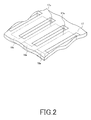
- FIG. 2 illustrates a position of a space-partitioning wall 17 and an injector 18a of an injector unit 18.
- the space-partitioning wall 17 is formed from a plate-shaped insulting member.
- the space-partitioning wall 17 is disposed between the feeding pathway and the plasma-generating electrode 16a above the feeding pathway of the film F.
- the space-partitioning wall faces the plasma-generating electrode 16a.
- the space-partitioning wall forms the plasma-generating space between the plasma-generating electrode 16a and the space-partitioning wall.
- a surface of the space-partitioning wall 17 that faces the plasma-generating electrodes 16a is composed of the grounding electrode 16b.
- the slit-shaped through holes 17a are disposed at spaced intervals along the feeding direction of the film F in the space-partitioning wall 17.
- the through holes 17a communicate the plasma-generating space above the space-partitioning wall 17 and a space between the feeding pathway of the film F and the plasma-generating electrode 16a. It is preferable that the through holes 17a extend in a direction that is perpendicular to the feeding direction of the film F. A radical atom or a radical molecule generated from plasma or part of plasma passes through the through holes 17a, as described hereinafter.
- the injector unit 18 is disposed between the space-partitioning wall 17 and the feeding pathway of the film F.
- the injector unit 18 includes a plurality of injectors 18a along the feeding pathway of the film F.
- Each of the plurality of injectors 18a is disposed so as to be sandwiched from both sides of the feeding direction by two through holes 17a that are adjacent each other in a feeding direction of the film F of the abovementioned through holes 17a.
- the layer-forming gas supply opening is disposed in each of the plurality of injectors 18a, and the layer-forming gas is output and supplied to the film F from the layer-forming gas supply opening.
- the plurality of injectors 18a form a row along the feeding pathway of the film F.
- the plurality of injectors 18a supplies the layer-forming gas to the film F during feeding by outputting the layer-forming gas as described above, and a layer of layer-forming component is formed on the film F.
- the layer-forming component is chemically adsorbed onto the film F. In other words, a gas is selected such that the film F chemically adsorbs the layer-forming component.
- the plurality of injectors 18a is aligned at some intervals.
- a radical atom, a radical molecule, or an ion of a reactive gas obtained from plasma P generated in the abovementioned plasma-generating space is downwardly supplied towards the film F via through holes 17a.
- the layer-forming device 10 is configured such that, the radical atom, the radical molecule, or the ion from each space between the adjacent injectors 18a is supplied to the layer of the layer-forming component formed on the film F.
- a dummy injector 18b is disposed on both sides of the row of the plurality of injectors 18a.
- the dummy injector 18b lacks a layer-forming gas supply function.
- the dummy injector 18b is disposed such that the same space is formed between the dummy injector 18b and an adjacent injector 18a as that formed between the two adjacent injectors 18a. And the radical atom or the radical molecule is supplied to the film F from the space.
- the dummy injector 18b that does not supply the reactive gas to the film F is disposed further on a downstream side of the feeding direction away from the furthest downstream injector positioned on a furthest downstream side of the feeding direction of the film F. It is preferable that the dummy injector 18b is disposed so as to be spaced at an interval away from the furthest downstream injector, such that the furthest downstream through hole positioned on a furthest downstream side of the feeding direction of the through holes 17a of the space-partitioning wall 17 is positioned between the dummy injector 18b and the furthest downstream injector.
- the dummy injectors 18b are disposed on both sides of the plurality of injectors 18a aligned into a single row (as shown in FIG. 1 ), and also that the slit-shaped through holes 17a are disposed at a position in a feeding direction between the dummy injectors 18b and both sides of the plurality of injectors 18.
- the gas supply holes are disposed in one of the side walls (a side wall of the right side of FIG. 1 ) of the layer-forming container 24 below the space-partitioning wall 17.
- the gas supply pipe connected to a below-mentioned purge gas source 20c is connected to the gas supply hole.
- the purge gas is a gas used to more efficiently exhaust a layer-forming gas, reactive radical, radical molecule, radical atom, or the like that are no longer needed.
- the gas supply pipe that is connected to an inert gas source 20d and the gas supply pipe connected to a below-mentioned layer-forming gas source 20b is connected to each of the plurality of injectors 18a.
- the gas supply unit 20 includes: the reactive source 20a; the layer-forming gas source 20b; the purge gas source 20c; the inert gas source 20d; and mass flow controllers 20e, 20f (refer to FIG. 3 ).
- O 2 , O 3 , H 2 O, N 2 O, N 2 , NH 3 , or the like may be employed as the reactive gas supplied by the reactive gas source 20a.
- a metallo-organic compound gas that includes trimethyl aluminum (TMA), tetra ethyl methyl aminozirconium (TEMAZ), tetra ethyl methyl aminohafnium (TEMAHf), or aminosilane may be employed as the layer-forming gas supplied from the layer-forming gas source 20b.
- An inert gas including a nitrogen gas, an argon gas, a neon gas, or a helium gas may be employed as the purge gas supplied by the purge gas source 20c.
- An inert gas including a nitrogen gas, an argon gas, a neon gas, or a helium gas may be employed as the inert gas supplied by the inert gas source 20d.
- the inert gas does not react with the reactive gas and the layer-forming gas, and also does not react with the thin layer that is formed.
- the plurality of injectors 18a are disposed so as to be spaced at intervals; and the fed film F receives a supply of the layer-forming gas from the plurality of injectors 18a when passing by each of the plurality of injectors 18a, such that the layer-forming component of the layer-forming gas is chemically adsorbed onto the film F in atomic layer unit.
- the reactive gas is supplied to the plasma-generating space, and plasma P is generated using the plasma-generating gas between the grounding electrode 16b and the plasma-generating electrode 16a to which the high frequency voltage applied.
- the plasma P or the radical atom, the radical molecule, or the ion generated from the plasma P passes through the through holes 17a of the space-partitioning wall 17, the through hole disposed in a space between the plurality of injectors 18a, and finally reaches the top of the film F.
- the thin layer is formed by reacting, with the above radical molecule, radical atom, or ion, the layer-forming component in atomic layer unit that is adsorbed onto the film F by the supply of the layer-forming gas from the plurality of injectors 18a. Since the plurality of injectors 18a and spaces between the adjacent injectors 18a are alternately disposed, the thin layer formed on the film F is gradually thickened during the feeding of the film F.
- the film F for the layer-formation is fed by unwinding the roll of the film F (roll wound on rotary roller 14a or rotary roller 14b), and then the film F that has been subjected to a layer-forming process during feeding is wound to produce a roll of processed film (the first step). Furthermore, the film F is unwound from the roll of the processed film and is fed in order to thicken the thin layer on the film F, and then the film F that has been processed during feeding is wound to make a new roll of processed film (the second step). In addition, the target thickness of the formed layer on the film F can be obtained on the film by repeating the second step.
- each set of the sub-processes including:
- the layer-forming device 10 can form the thin layer on the film F.
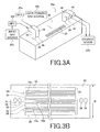
- FIG. 3A is schematic perspective view of the plurality of injectors 18a.
- FIG. 3A illustrate a substrate opposing surface 30 that faces the film F.
- the substrate opposing surface is illustrated so as to face upwards.
- FIG. 3B illustrates a substrate opposing surface 30 of the plurality of injectors 18a.
- the plurality of injectors 18a are disposed on a surface of the space-partitioning wall opposite to a surface that faces the plasma-generating electrode 16a, and the plurality of injectors 18a output and supply a layer-forming gas to the film F.
- the plurality of injectors 18a do not just simply supply a layer-forming gas, but rather the plurality of injectors 18a also suck the excess layer-forming gas that is not adsorbed onto the film F, and output an inert gas as a barrier gas so that the layer-forming gas is not dispersed from the injector 18a into the surrounding space between the adjacent injectors 18a.
- the plurality of slit-shaped openings 32 that extend in a direction perpendicular to the feeding direction of the film F are disposed in the substrate opposing surface 30.
- a length of the plurality of openings 32 is substantially identical to that of a width of the film F.
- the plurality of openings 32 are disposed in the substrate opposing surface 30 that includes: a layer-forming gas supply opening 50; first gas exhaust openings 52, 52; inert gas supply openings 54, 54; and second gas exhaust openings 56, 56.
- the layer-forming gas supply opening 50 is an opening for outputting and supplying the layer-forming gas towards the film F.
- the first gas exhaust openings 52, 52 are disposed on both sides of the feeding direction of film F with respect to the layer-forming gas supply opening 50, and the first gas exhaust openings 52, 52 are openings for suction of the excess gas existing above the film F.
- the inert gas supply openings 54, 54 are disposed on a far side of each of the first gas exhaust openings 52, 52 away from the layer-forming gas supply opening 50 in a feeding direction of the film F, and the inert gas supply openings 54, 54 supply the inert gas to the layer-forming component.
- Members 50a, 54a that block a portion of an opening are disposed along a lengthwise direction of the plurality of slit-shaped openings, on an opening surface of the inert gas supply openings 54, 54 and the film-forming gas supply opening 50.
- the members 50a, 54a are for suppressing, as much as possible, injection velocity of the layer-forming gas and the inert gas from the layer-forming gas supply opening 50 and the inert gas supply openings 54, 54, and for supplying the layer-forming gas and the inert gas gradually to the surface of the film F.
- a width W of the injectors 18a (see, FIG.
- each of the layer-forming gas supply opening 50, the first gas exhaust openings 52, 52, the inert gas supply openings 54, 54, and the second gas exhaust openings 56, 56 is, e.g., 1 to 5 mm.
- Gas supply ports 34, 36 and gas exhaust ports 38, 40 form elliptically-shaped openings that are disposed on the substrate opposing surface 30, in addition to the plurality of openings 32, in order to supply and exhaust the gas.
- the inert gas supply pipe 42 is connected to the gas supply port 34.
- the inert gas supply pipe 42 is connected to the inert gas source 20d via the mass flow controller 20f.
- the mass flow controller 20f controls a supply amount of the inert gas into the layer-forming space.
- the layer-forming gas supply pipe 44 is connected to the gas supply port 36.
- the layer-forming gas supply pipe 44 is connected to the layer-forming gas source 20b via the mass flow controller 20e.
- the mass flow controller 20e controls the supply amount of the layer-forming gas into layer-forming space.
- the exhaust pipes 46, 48 are each connected to the gas exhaust ports 38, 40.
- the exhaust pipes 46, 48 are connected to the exhaust device 22b.
- the gas supply ports 34, 36, and the gas exhaust ports 38, 40 are not only limited to being disposed on the substrate opposing surface 30 of each injector 18a.
- the gas supply ports 34, 36 and the gas exhaust ports 38, 40 may be disposed on another surface of the injector 18a.
- the second gas exhaust ports 56, 56 are included in the present embodiment, the second gas exhaust ports 56, 56 are not required. However, it is preferable that the second gas exhaust ports 56, 56 are included, from a point of view that a supply of a radical atom or radical molecule to a film F that is needed for the layer-forming is not avoided by reliably exhausting the inert gas and by streaming the inert gas in a space between the adjacent injectors 18a.
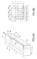
- FIG. 4A illustrates a three-dimensional view of a gas flow passage of the layer-forming gas, a gas flow passage of the inert gas, and an exhaust passage in each injector 18a; and FIG. 4B illustrates a cross-sectional view of the injectors 18a along line X - X' in FIG. 4A .
- a tubular layer-forming continuous hole that is disposed in the injector 18a extends from the gas supply port 36 that is connected to the layer-forming gas supply pipe 44.
- the layer-forming continuous hole includes: an upward part 60a that goes upward along a height direction H of the injector 18a; a storage part 60b that forms a long-narrow space that extends in lengthwise direction of the injector 18a in the injector 18a; and downward part 60c that goes downward along height direction H towards the layer-forming gas supply opening 50 from the storage part 60b ( see, FIG. 4B ).
- the exhaust connect hole which extends from the exhaust port 38 that is connected to the exhaust pipe 46, is disposed in the injector 18a.
- the exhaust continuous hole includes: an upward part 62a that goes upward along the height direction H of the injector 18a; a ring part 62b that forms a ring shape in the injector 18a and that is connected to the upward part 62a; and a downward part 62c that goes downward along the height direction H towards each of the two gas exhaust openings 52, 52 from the ring part 62b ( see, FIG. 4B ).
- the tubular inert gas continuous hole which extends from the gas supply port 34 that is connected to the inert gas supply pipe 42, is disposed in the injector 18a.
- the inert gas continuous hole includes: an upward part 64a that goes upward along the height direction H of the injector 18a; a ring part 64b that forms a ring shape in the injector 18a and that is connected to the upward part 64a; and downward part 64c that goes downward along the height direction H towards the inert gas supply openings 54, 54 from the ring part 64b ( see, FIG. 4B ).
- the exhaust continuous hole which extends from the exhaust port 40 that is connected to the exhaust pipe 48, is disposed in the injector 18a.
- the exhaust continuous hole includes: an upward part 66a that goes upward along the height direction H of the injector 18a; a ring part 66b that forms a ring shape in the injector 18a and that is connected to the upward part 66a; and downward part 66c that goes downward along the height direction H towards the second gas exhaust openings 56, 56 from the ring part 66b ( see, FIG. 4B ).
- the structure is divided at a position of a ring part and a storage part along dividing line A - E.
- the layer-forming device 10 forms the plasma-generating space that generates plasma P by using the plasma-generating electrode 16a disposed in the layer-forming container 12, plasma P or a radical molecule, radical atom, or ion generated from the plasma P passes from the through hole 17a disposed at intervals into the space-partitioning wall 17, and is supplied to the film F from a space between the injectors 18a.
- the layer-forming gas from the injectors 18a is supplied to the film F and the layer-forming component is adsorbed. Accordingly, the layer-forming component that is formed by injecting the layer-forming gas from the injector 18a forms a thin layer by reacting with the radical molecule, the radical atom, or the ion.
- the layer-forming device 10 includes a simplified structure that has a through hole and a space allowing plasma, a radical molecule, a radical atom, or an ion to pass through between an injector 18a and an adjacent injector 18a in the feeding direction of the film F.
- the thickness of the thin layer is thickened every time the film F passes by a space between adjacent injectors 18a. Subsequently, the layer forming on the film F can be performed very efficiently.
- the plasma-generating space that generates plasma by a capacitively coupled plasma method is formed above the space-partitioning wall 17. Because the through holes 17a are disposed in the space-partitioning wall 17, the plasma, the radical atom, or the radical molecule may be easily supplied downward to the feeding passage of the film F from the space-partitioning wall 17. Accordingly, the radical atom or the radical molecule can be supplied to the film F via a simplified structure.
- the plurality of injectors 18a are disposed on a surface of the space-partitioning wall opposite to a surface that faces the plasma-generating electrode. Subsequently, the layer-forming gas can be supplied to the film F using a simplified structure.
- the dummy injector 18b that does not supply reactive gas to the film F is disposed further on the downstream side of the feeding direction away from a furthest downstream injector positioned on a furthest downstream side in a feeding direction of the film F.
- the dummy injector 18b is disposed so as to be spaced at an interval away from the furthest downstream injector, such that the furthest downstream through hole positioned on a furthest downstream side of the feeding direction of the through holes 17a of the space-partitioning wall 17 is positioned between the dummy injector 18b and the furthest downstream injector.
- a thin layer may be highly efficiently formed via ALD.
- the feeding direction of the film F can be sequentially switched. Accordingly, the film F can move backward and forward several times, passing by the plurality of injectors 18a and regions between the plurality of injectors 18a until the thickness of the layer formed on the film F reaches a desired thickness. As a result, the thickness of the layer on the film F can be very efficiently achieved.
Landscapes
- Chemical & Material Sciences (AREA)
- Engineering & Computer Science (AREA)
- Physics & Mathematics (AREA)
- Plasma & Fusion (AREA)
- Chemical Kinetics & Catalysis (AREA)
- General Chemical & Material Sciences (AREA)
- Materials Engineering (AREA)
- Mechanical Engineering (AREA)
- Metallurgy (AREA)
- Organic Chemistry (AREA)
- Analytical Chemistry (AREA)
- Electromagnetism (AREA)
- Chemical Vapour Deposition (AREA)
- Plasma Technology (AREA)
- Spectroscopy & Molecular Physics (AREA)
Abstract
Description
- A present disclosure relates to a layer-forming device that forms a thin layer in atomic layer unit using a layer-forming gas and a reactive gas, and a layer-forming method.
- Recently, a layer-forming method according to Atomic Layer Deposition (ALD) is known, in which a thin layer is formed in atomic layer unit. In ALD, a thin layer configuration having a plurality of stacked layers in atomic layer unit is formed by alternatively supplying a layer-forming gas and a reactive gas as a precursor gases. Because a thin layer obtained by the ALD is able to produce an extremely thin layer thickness of approximately 0.1 nm, the ALD may be effectively utilized as a highly precise layer-forming process in the production of various devices.
- For example, a layer-forming device is known that allows for production costs to be reduced and for flexibility to be enhanced during a layer-forming process (see, Patent Literature 1).
- The abovementioned layer-forming device includes: a feeding mechanism that feeds a base material as a body on which a layer is formed, and the feeding mechanism includes a plurality of roller members; and a plurality of head parts that are disposed so as to face the roller member, and plurality of head parts act as a gas source capable of locally outputting a precursor gas for performing atomic layer deposition to the base material. In addition, each head part is constructed to allow a separate output of a plurality of types of precursor gases.
- Patent Literature 1:
JP-A 2011-137208 - A layer-forming device employs a flexible substrate, film-shaped substrate, or sheet-shaped substrate. The layer-forming device alternately supplies different gases to the substrate by controlling the substrate to pass by a plurality of head parts while feeding the substrate via a guide roller.
- The layer-forming device forms a thin layer in atomic layer unit by alternately supplying different gases to the substrate, and by reacting a supplied gas and a layer of a layer-forming component formed on the substrate of another gas that has been supplied. However, the reaction is temperature dependent. Therefore, it is necessary to increase a temperature of the substrate in order to speed up the reaction. But, in a case where using a flexible resin-type film as the substrate, the substrate can only be raised from a heat-resistant temperature thereof up to 80 to 100°C (only a low-temperature process may be performed).
- On the other hand, a layer-forming process is known in ALD using plasma (hereinafter referred to as "plasma ALD") that allows for layer-forming at a low substrate temperature (80 to 100°C) to the same degree as layer-forming at a high substrate temperature (300 to 400°C).
- However, in plasma ALD device that performs layer deposition on the substrate during feeding, a highly reactive radical atom, radical molecule, or ion generated from plasma is employed. Accordingly, wherever possible, a combination of any layer-forming gas with the reactive radical atom, the radical molecule, or the ion in a space should be avoided.
- In addition, nothing is known at the present time with respect to a plasma ALD device that forms layer on a fed substrate that allows for layer-forming to be more efficiently performed, or a device configuration that is capable of achieving simplified plasma ALD configuration.
- An objective of the present disclosure is to provide a layer-forming device forming layer on the substrate during feeding using plasma ALD that allows for layer-forming to be more efficiently conducted, and also to provide a layer-forming device forming layer on the substrate during feeding using plasma ALD that may achieve a simplified plasma ALD configuration and a layer-forming method using the layer-forming device.
- In an embodiment of the present disclosure, a layer-forming device is disclosed that forms a thin layer in atomic layer unit using a layer-forming gas and a reactive gas. The layer-forming device includes:
- a layer-forming container;
- a feeding mechanism configured to feed a substrate for layer-forming inside the layer-forming container;
- a plasma-generating electrode disposed to face a feeding pathway of the substrate during feeding, the plasma-generating electrode configured to receive a supply of electric power to generate plasma using a reactive gas inside the layer-forming container;
- a space-partitioning wall disposed between the feeding pathway of the substrate and the plasma-generating electrode, the space-partitioning wall forming a plasma-generating space between the plasma-generating electrode and the space-partitioning wall, the space-partitioning wall having a plurality of slit-shaped through holes for communicating the plasma-generating space and a space between the feeding pathway of the substrate and the plasma-generating electrode, the through holes being disposed at intervals along a feeding direction of the substrate; and
- gas injectors, each of the gas injectors being disposed between the space-partitioning wall and the feeding pathway, and being sandwiched from both sides of a feeding direction by adjacent through holes of the plurality of through holes, each of the gas injectors configured to supply the layer-forming gas from a layer-forming gas supply opening thereof to the substrate.
- Preferably, an opposing surface of the space-partitioning wall that faces the plasma-generating electrode is composed of a grounding electrode.
- Each of the gas injectors is preferably disposed on a surface of the space-partitioning wall opposite to an opposing surface of the space-partitioning wall that faces the plasma-generating electrode.
- A gas supply hole for supplying the reactive gas inside the plasma-generating space is preferably disposed in a side wall of the layer-forming container.
- In the device, a dummy injector configured not to supply the layer-forming gas to the substrate is preferably disposed further on a downstream side of the feeding direction than a furthest downstream gas injector positioned at a furthest downstream side of the feeding direction of the substrate, and the dummy injector is disposed so as to be spaced at an interval away from the furthest downstream gas injector, such that a furthest downstream through hole positioned on a furthest downstream side of the feeding direction of the plurality of through holes is positioned between the dummy injector and the furthest downstream injector.
- The feeding mechanism preferably includes a pair of rotary rollers, the substrate is a long flexible film, and the film is wound onto one rotary roller before feeding.
- Each rotary roller is preferably configured to rotate in different directions.
- In an embodiment of the present disclosure, a layer-forming method is disclosed that employs a layer-forming device. In such a case, the layer-forming device includes:
- a layer-forming container,
- a feeding mechanism configured to feed a substrate for layer-forming inside the layer-forming container,
- a plasma-generating electrode disposed to face a feeding pathway of the substrate during feeding, the plasma-generating electrode configured to receive a supply of electric power to generate plasma using a reactive gas inside the layer-forming container,
- a space-partitioning wall disposed between the feeding pathway of the substrate and the plasma-generating electrode, the space-partitioning wall forming a plasma-generating space between the plasma-generating electrode and the space-partitioning wall, the space-partitioning wall having a plurality of slit-shaped through holes for communicating the plasma-generating space and a space between the feeding pathway of the substrate and the plasma-generating electrode disposed at intervals along a feeding direction of the substrate, and
- gas injectors, each of the gas injectors being disposed between the space-partitioning wall and the feeding pathway, and being sandwiched from both sides of a feeding direction by adjacent through holes of the plurality of through holes, each of the gas injectors configured to supply the layer-forming gas from a layer-forming gas supply opening thereof to the substrate, the substrate being a film from a roll of film,
- the layer deposition method comprising:
- a first step of producing a roll of processed film by unwinding the film from the roll of film, then feeding the film for layer-forming process, and winding the film processed during feeding; and
- a second step of making a new roll of processed film by again unwinding the processed film from the roll of processed film, then feeding the processed film in order to increase a layer thickness on the processed film, and winding the processed film, wherein
- a target layer thickness is obtained by repeating the second step.
- In the first step and the second step, a plurality of sets of sub-processes are preferably conducted to the film, each set of sub-processes including :
- a layer-forming component deposition, in which a layer of a layer-forming component is formed on the film by supplying the layer-forming gas from the gas injector to the film, and
- a reaction, in which the layer of the layer-forming component formed on the film is reacted with the plasma or a radical generated from the plasma supplied to the film, and wherein
- a final sub-process before winding the film is the reaction.
- A layer-forming device and a layer-forming method allow for layer-forming to be more efficiently conducted, and for a simplified ALD configuration to be achieved.
-
-
FIG. 1 illustrates a schematic drawing of a layer-forming device of a present embodiment; -
FIG. 2 illustrates a space-partitioning wall and a through hole, which is employed in the layer-forming device illustrated inFIG. 1 ; -
FIG. 3A illustrates a perspective view of a gas injector employed in the layer-forming device of the present embodiment, andFIG 3B illustrates a substrate opposing substrate of a gas injector illustrated inFIG 3A ; and -
FIG. 4A illustrates a gas flow passage of the layer-forming gas and the inert gas and an exhaust passage inside the gas injector that is employed in the layer-forming device of the present embodiment, andFIG. 4B illustrates a cross-sectional view of a gas injector along line X-X' inFIG. 4A . - Hereinafter, a layer-forming device of a present disclosure will be described in detail.
-
FIG. 1 illustrates a schematic drawing of a layer-forming device of a present embodiment. A layer-formingdevice 10 is a device that forms a thin layer in atomic layer unit using a layer-forming gas and a reactive gas. The layer-formingdevice 10 includes: a layer-formingcontainer 12; afeeding mechanism 14; a plasma-generatingunit 16; a space-partitioning wall 17; aninjector unit 18; agas supply unit 20; and anexhaust unit 22. The layer-formingdevice 10 has the below-mentioned configuration. Thefeeding mechanism 14 feeds a substrate for layer-forming inside the layer-formingcontainer 12. The plasma-generatingunit 16 includes plasma-generating electrode. The plasma-generating electrode in the layer-formingcontainer 12 is disposed so as to face a feeding pathway of the substrate during feeding. The plasma-generating electrode generates plasma by using a reactive gas inside a layer-forming space as a result of a supply of electric power received. The space-partitioning wall 17 in the layer-formingcontainer 12 is disposed between the feeding pathway of the substrate and the plasma-generating electrode, and the space-partitioning wall 17 forms a plasma-generating space between plasma-generating electrode and the space-partitioning wall 17. The space-partitioning wall has a plurality of slit-shaped through holes, which communicate the plasma generating space and a space between the feeding pathway of the substrate and the plasma-generating electrode, disposed at intervals along a feeding direction of the substrate. A radical or an ion generated from the plasma or a part of the plasma may pass through the though holes. - The
injector unit 18 includes a plurality of gas injectors (hereinafter, simply referred to as "injector"). Each injector outputs a layer-forming gas from a layer-forming gas supply opening, and supplies the layer-forming gas to the substrate. Each injector is disposed between the space-partitioning wall 17 and the feeding pathway, and sandwiched by adjacent through holes of the though holes in the space-partitioning wall 17 from both sides of the feeding direction of the substrate. - Hereinafter, various configurations of the layer-forming
device 10 will be described in detail. The present embodiment describes an extremely thin glass plate or resin film as the substrate for layer-formation. The present embodiment employs a long flexible substrate that can be wound into a rolled shape as a substrate for layer-formation. However, the substrate employed in the present embodiment is not limited to a flexible substrate. For example, a one-piece unflexible plate-shaped substrate may be used as the substrate for layer-formation. - As illustrated in
FIG. 1 , thefeeding mechanism 14, a plasma-generatingelectrode 16a associated with the plasma-generatingunit 16, and theinjector unit 18, are mainly disposed within the layer-forming space in the layer-formingcontainer 12. The layer-formingcontainer 12 is for layer-formation on the substrate inside the layer-forming space by maintaining the layer-forming space at a predetermined pressure or at a reduced pressure. Athermal heater 24 for setting ambient atmosphere inside the layer-forming space to a desired temperature during the layer-forming is disposed in each wall surface of an outer periphery of thecontainer 12. - The substrate for layer-formation that is fed by the
feeding mechanism 14 is a flexible film F from a roll of film (a roll wound onto arotary roller 14a or arotary roller 14b). Thefeeding mechanism 14 includes therotary rollers container 12. Therotary rollers rotary rollers rotary rollers feeding mechanism 14, one of therotary rollers rotary rollers rotary roller 14b) by the rotation of therotary roller rotary roller 14a. At such a time, the unwound film F is fed in one direction for layer-forming process, then the film F subjected to layer-forming process during feeding is wound onto therotary roller 14a, thereby producing a roll of processed film.FIG. 1 illustrates the film F being fed from therotary roller 14b torotary roller 14a, and the film F being wound by therotary roller 14a. - In the present embodiment, it is preferable that the layer-formation on the film F is repeated in order to thicken a layer thickness of a formed thin layer on the film F. At such a time, it is preferable that the
feeding mechanism 14 feeds from therotary roller 14a towards therotary roller 14b, i.e., in a direction opposing the feeding direction during the previous layer-forming process, by again unwinding the roll of processed film obtained by winding of the processed film F onto therotary roller 14a after layer-forming process. During feeding, the film F has the layer thickened. Therotary roller 14b winds the processed film F to make a new roll of processed film. Next, thefeeding mechanism 14 feeds the film F from therotary roller 14b towards therotary roller 14a, i.e., in a direction opposing the feeding direction during the previous layer-forming process, in order to further thicken the layer thickness. During feeding, a layer thickness becomes thickened. Therotary roller 14a winds the processed film F to make a new roll of processed film. Accordingly, it is preferable that a target layer thickness is obtained on film F by thickening the layer thickness of the thin layer while repeating the feeding of the film F towards different directions. In other words, it is preferable that each of therotary rollers - The
exhaust unit 22 includesexhaust devices exhaust unit 22 maintains a constant pressure by exhausting the gas inside the plasma-generating space where plasma is generated and by exhausting the gas inside the layer-forming space inside thecontainer 12. Theexhaust device 22a exhausts the reactive gas inside the below-mentioned plasma-generating space. Theexhaust device 22b exhausts the gas inside the layer-forming space that includes the plasma-generating space below the plasma-generatingelectrode 16a. - The plasma-generating
unit 16 includes: the plasma-generatingelectrode 16a; agrounding electrode 16b; amatching box 16c; and a high frequencyelectric power source 16d. The plasma-generatingunit 16 generates a reactive substance that reacts with the layer-forming component adsorbed on the film F of the layer-forming gas. The space-partitioning wall 17 is disposed inside the layer-formingcontainer 24 so as traverse the layer-formingcontainer 24. The space-partitioning wall 17 is disposed between the feeding pathway of the film F and the plasma-generatingelectrode 16a. The plasma-generatingelectrode 16a in the film-formingcontainer 12 is a plate-shaped electrode. The plasma-generatingelectrode 16a is disposed above the feeding pathway of the film F so as to face towards the feeding pathway along the feeding pathway of the film F. It is preferable that the plasma-generatingelectrode 16a be disposed in parallel to the feeding pathway. The plasma-generatingelectrode 16a generates plasma using the reactive gas inside the film-forming space as a result of the electric power supply received thereto. Specifically, electric supply lines are used to connect the plasma-generatingelectrode 16a to the high frequencyelectric power source 16d through a ceiling surface of the layer-formingcontainer 12 via thematching box 16c. The high frequencyelectric power source 16d supplies a high frequency electric voltage to the plasma-generating electrode, e.g., a voltage of 13.56 MHz. - The
grounding electrode 16b is disposed on a surface of the space-partitioning wall 17 so as to face the plasma-generatingelectrode 16a. In other words, the opposing surface that faces the plasma-generatingelectrode 16a of the space-partitioning wall 17 is composed of thegrounding electrode 16b. The plasma P is generated using the reactive gas supplied to the space between the plasma-generatingelectrode 16a and thegrounding electrode 16b, by applying high frequency voltage to the plasma-generatingelectrode 16a. In other words, the space between the plasma-generatingelectrode 16a and thegrounding electrode 16b is the plasma-generating space. - The present embodiment can employ an inductively coupled plasma method or a conventional plasma-generating method, in addition to a capacitively coupled plasma method that generates plasma between electrodes, in which the plasma-generating
electrode 16a and thegrounding electrode 16b are disposed to face each other. - The electric supply lines that supply the high frequency electric power to the high frequency
electric power 16a are connected to thematching box 16c outside the layer-formingcontainer 24 via holes disposed in a ceiling surface of the layer-formingcontainer 24. At such a time, the holes are sealed in the insulatingbody 16e. Moreover, an insulatingbody plate 16f made of a ceramic plate or the like is disposed in an outer periphery of the plasma-generatingelectrode 16a. Accordingly, the plasma-generating space is separated from a space above the plasma-generatingelectrode 16a. - The gas supply holes are disposed on one side wall (a side wall of a right side in
FIG. 1 ) of the layer-formingcontainer 12 that defines the plasma-forming space. The gas supply holes are connected to a gas supply pipe that is connected to the below-mentionedreactive gas source 20a, as illustrated inFIG. 1 . The reactive gas is supplied inside the plasma-reacting space via the gas supply holes. In other words, the gas supply holes for supplying reactive gas inside the plasma-reacting space are disposed on a side wall of the layer-formingcontainer 12. Moreover, the gas exhaust holes disposed on another side wall (a side wall of a left side inFIG. 1 ) of the layer-formingcontainer 12 that defines the plasma-generating space. The gas exhaust holes are connected to the exhaust pipe that is connected to theexhaust device 22a, as illustrated inFIG. 1 . -
FIG. 2 illustrates a position of a space-partitioning wall 17 and aninjector 18a of aninjector unit 18. - The space-
partitioning wall 17 is formed from a plate-shaped insulting member. The space-partitioning wall 17 is disposed between the feeding pathway and the plasma-generatingelectrode 16a above the feeding pathway of the film F. The space-partitioning wall faces the plasma-generatingelectrode 16a. The space-partitioning wall forms the plasma-generating space between the plasma-generatingelectrode 16a and the space-partitioning wall. A surface of the space-partitioning wall 17 that faces the plasma-generatingelectrodes 16a is composed of thegrounding electrode 16b. The slit-shaped throughholes 17a are disposed at spaced intervals along the feeding direction of the film F in the space-partitioning wall 17. The throughholes 17a communicate the plasma-generating space above the space-partitioning wall 17 and a space between the feeding pathway of the film F and the plasma-generatingelectrode 16a. It is preferable that the throughholes 17a extend in a direction that is perpendicular to the feeding direction of the film F. A radical atom or a radical molecule generated from plasma or part of plasma passes through the throughholes 17a, as described hereinafter. - The
injector unit 18 is disposed between the space-partitioning wall 17 and the feeding pathway of the film F. Theinjector unit 18 includes a plurality ofinjectors 18a along the feeding pathway of the film F. Each of the plurality ofinjectors 18a is disposed so as to be sandwiched from both sides of the feeding direction by two throughholes 17a that are adjacent each other in a feeding direction of the film F of the abovementioned throughholes 17a. As mentioned hereinafter, the layer-forming gas supply opening is disposed in each of the plurality ofinjectors 18a, and the layer-forming gas is output and supplied to the film F from the layer-forming gas supply opening. - The plurality of
injectors 18a form a row along the feeding pathway of the film F. The plurality ofinjectors 18a supplies the layer-forming gas to the film F during feeding by outputting the layer-forming gas as described above, and a layer of layer-forming component is formed on the film F. The layer-forming component is chemically adsorbed onto the film F. In other words, a gas is selected such that the film F chemically adsorbs the layer-forming component. The plurality ofinjectors 18a is aligned at some intervals. Accordingly, in a case where a layer of the layer-forming component adsorbed onto the film F passes through a space between the adjacent injectors after the component being adsorbed on the film F, a radical atom, a radical molecule, or an ion of a reactive gas obtained from plasma P generated in the abovementioned plasma-generating space is downwardly supplied towards the film F via throughholes 17a. In other words, the layer-formingdevice 10 is configured such that, the radical atom, the radical molecule, or the ion from each space between theadjacent injectors 18a is supplied to the layer of the layer-forming component formed on the film F. - A
dummy injector 18b is disposed on both sides of the row of the plurality ofinjectors 18a. Thedummy injector 18b lacks a layer-forming gas supply function. Thedummy injector 18b is disposed such that the same space is formed between thedummy injector 18b and anadjacent injector 18a as that formed between the twoadjacent injectors 18a. And the radical atom or the radical molecule is supplied to the film F from the space. - Accordingly, the
dummy injector 18b that does not supply the reactive gas to the film F is disposed further on a downstream side of the feeding direction away from the furthest downstream injector positioned on a furthest downstream side of the feeding direction of the film F. It is preferable that thedummy injector 18b is disposed so as to be spaced at an interval away from the furthest downstream injector, such that the furthest downstream through hole positioned on a furthest downstream side of the feeding direction of the throughholes 17a of the space-partitioning wall 17 is positioned between thedummy injector 18b and the furthest downstream injector. Accordingly, in a case where the feeding and the layer-forming of the film F is repeated by rotating therotary rollers dummy injectors 18b are disposed on both sides of the plurality ofinjectors 18a aligned into a single row (as shown inFIG. 1 ), and also that the slit-shaped throughholes 17a are disposed at a position in a feeding direction between thedummy injectors 18b and both sides of the plurality ofinjectors 18. - The gas supply holes are disposed in one of the side walls (a side wall of the right side of
FIG. 1 ) of the layer-formingcontainer 24 below the space-partitioning wall 17. The gas supply pipe connected to a below-mentionedpurge gas source 20c is connected to the gas supply hole. The purge gas is a gas used to more efficiently exhaust a layer-forming gas, reactive radical, radical molecule, radical atom, or the like that are no longer needed. - In addition, the gas supply pipe that is connected to an
inert gas source 20d and the gas supply pipe connected to a below-mentioned layer-forminggas source 20b is connected to each of the plurality ofinjectors 18a. - The
gas supply unit 20 includes: thereactive source 20a; the layer-forminggas source 20b; thepurge gas source 20c; theinert gas source 20d; andmass flow controllers FIG. 3 ). - O2, O3, H2O, N2O, N2, NH3, or the like, may be employed as the reactive gas supplied by the
reactive gas source 20a. A metallo-organic compound gas that includes trimethyl aluminum (TMA), tetra ethyl methyl aminozirconium (TEMAZ), tetra ethyl methyl aminohafnium (TEMAHf), or aminosilane may be employed as the layer-forming gas supplied from the layer-forminggas source 20b. An inert gas including a nitrogen gas, an argon gas, a neon gas, or a helium gas may be employed as the purge gas supplied by thepurge gas source 20c. An inert gas including a nitrogen gas, an argon gas, a neon gas, or a helium gas may be employed as the inert gas supplied by theinert gas source 20d. The inert gas does not react with the reactive gas and the layer-forming gas, and also does not react with the thin layer that is formed. - In the layer-forming
device 10, the plurality ofinjectors 18a are disposed so as to be spaced at intervals; and the fed film F receives a supply of the layer-forming gas from the plurality ofinjectors 18a when passing by each of the plurality ofinjectors 18a, such that the layer-forming component of the layer-forming gas is chemically adsorbed onto the film F in atomic layer unit. On the other hand, during the feeding of the film F, the reactive gas is supplied to the plasma-generating space, and plasma P is generated using the plasma-generating gas between the groundingelectrode 16b and the plasma-generatingelectrode 16a to which the high frequency voltage applied. The plasma P or the radical atom, the radical molecule, or the ion generated from the plasma P passes through the throughholes 17a of the space-partitioning wall 17, the through hole disposed in a space between the plurality ofinjectors 18a, and finally reaches the top of the film F. Accordingly, the thin layer is formed by reacting, with the above radical molecule, radical atom, or ion, the layer-forming component in atomic layer unit that is adsorbed onto the film F by the supply of the layer-forming gas from the plurality ofinjectors 18a. Since the plurality ofinjectors 18a and spaces between theadjacent injectors 18a are alternately disposed, the thin layer formed on the film F is gradually thickened during the feeding of the film F. - Accordingly, the film F for the layer-formation is fed by unwinding the roll of the film F (roll wound on
rotary roller 14a orrotary roller 14b), and then the film F that has been subjected to a layer-forming process during feeding is wound to produce a roll of processed film (the first step). Furthermore, the film F is unwound from the roll of the processed film and is fed in order to thicken the thin layer on the film F, and then the film F that has been processed during feeding is wound to make a new roll of processed film (the second step). In addition, the target thickness of the formed layer on the film F can be obtained on the film by repeating the second step. - In the first step and the second step, a plurality of sets of sub-processes is conducted on the film F, each set of the sub-processes including:
- a layer-forming component deposition, in which a layer of a layer-forming deposition component is formed on the film by supplying the layer-forming gas from the plurality of
gas injectors 18a to the film F, and - a reaction, in which the layer of the layer-forming component formed on the film is reacted with the supplied plasma or a radical generated from the plasma to the film F. In the above case, it is preferable that the final sub-process before the winding of the film F is the reactions rather than the above a layer-forming component deposition. Accordingly, an uppermost surface layer of the thin layer on the film F when winding the film F is a stable layer obtained after a layer-forming component is reacted with a neutral radical, or the like. As a result, it is possible for a stable thin layer to be retained even when the uppermost layer is brought into contact with a rear surface of the film F after the film F is wound as a roll.
- In this way, the layer-forming
device 10 can form the thin layer on the film F. -
FIG. 3A is schematic perspective view of the plurality ofinjectors 18a.FIG. 3A illustrate asubstrate opposing surface 30 that faces the film F. InFIG.3A , the substrate opposing surface is illustrated so as to face upwards.FIG. 3B illustrates asubstrate opposing surface 30 of the plurality ofinjectors 18a. - The plurality of
injectors 18a are disposed on a surface of the space-partitioning wall opposite to a surface that faces the plasma-generatingelectrode 16a, and the plurality ofinjectors 18a output and supply a layer-forming gas to the film F. However, the plurality ofinjectors 18a do not just simply supply a layer-forming gas, but rather the plurality ofinjectors 18a also suck the excess layer-forming gas that is not adsorbed onto the film F, and output an inert gas as a barrier gas so that the layer-forming gas is not dispersed from theinjector 18a into the surrounding space between theadjacent injectors 18a. - The plurality of slit-shaped
openings 32 that extend in a direction perpendicular to the feeding direction of the film F are disposed in thesubstrate opposing surface 30. A length of the plurality ofopenings 32 is substantially identical to that of a width of the film F. As illustrated inFIG. 3B , the plurality ofopenings 32 are disposed in thesubstrate opposing surface 30 that includes: a layer-forminggas supply opening 50; firstgas exhaust openings gas supply openings gas exhaust openings - The layer-forming
gas supply opening 50 is an opening for outputting and supplying the layer-forming gas towards the film F. The firstgas exhaust openings gas supply opening 50, and the firstgas exhaust openings gas supply openings gas exhaust openings gas supply opening 50 in a feeding direction of the film F, and the inertgas supply openings -
Members gas supply openings gas supply opening 50. Themembers gas supply opening 50 and the inertgas supply openings injectors 18a (see,FIG. 3B ) is, e.g., 20 to 40 mm, and the opening width of each of the layer-forminggas supply opening 50, the firstgas exhaust openings gas supply openings gas exhaust openings -
Gas supply ports gas exhaust ports substrate opposing surface 30, in addition to the plurality ofopenings 32, in order to supply and exhaust the gas. - As illustrated in
FIG. 3A , the inertgas supply pipe 42 is connected to thegas supply port 34. The inertgas supply pipe 42 is connected to theinert gas source 20d via themass flow controller 20f. Themass flow controller 20f controls a supply amount of the inert gas into the layer-forming space. - As illustrated in
FIG. 3A , the layer-forminggas supply pipe 44 is connected to thegas supply port 36. The layer-forminggas supply pipe 44 is connected to the layer-forminggas source 20b via themass flow controller 20e. Themass flow controller 20e controls the supply amount of the layer-forming gas into layer-forming space. - As illustrated in
FIG. 3A , theexhaust pipes gas exhaust ports exhaust pipes exhaust device 22b. - In the present embodiment, the
gas supply ports gas exhaust ports substrate opposing surface 30 of eachinjector 18a. Thegas supply ports gas exhaust ports injector 18a. - Although the second
gas exhaust ports gas exhaust ports gas exhaust ports adjacent injectors 18a. -
FIG. 4A illustrates a three-dimensional view of a gas flow passage of the layer-forming gas, a gas flow passage of the inert gas, and an exhaust passage in eachinjector 18a; andFIG. 4B illustrates a cross-sectional view of theinjectors 18a along line X - X' inFIG. 4A . - As illustrated in
FIG. 4A , a tubular layer-forming continuous hole that is disposed in theinjector 18a extends from thegas supply port 36 that is connected to the layer-forminggas supply pipe 44. The layer-forming continuous hole includes: anupward part 60a that goes upward along a height direction H of theinjector 18a; astorage part 60b that forms a long-narrow space that extends in lengthwise direction of theinjector 18a in theinjector 18a; and downward part 60c that goes downward along height direction H towards the layer-forminggas supply opening 50 from thestorage part 60b (see,FIG. 4B ). - Moreover, the exhaust connect hole, which extends from the
exhaust port 38 that is connected to theexhaust pipe 46, is disposed in theinjector 18a. The exhaust continuous hole includes: anupward part 62a that goes upward along the height direction H of theinjector 18a; aring part 62b that forms a ring shape in theinjector 18a and that is connected to theupward part 62a; and a downward part 62c that goes downward along the height direction H towards each of the twogas exhaust openings ring part 62b (see,FIG. 4B ). - In addition, the tubular inert gas continuous hole, which extends from the
gas supply port 34 that is connected to the inertgas supply pipe 42, is disposed in theinjector 18a. The inert gas continuous hole includes: anupward part 64a that goes upward along the height direction H of theinjector 18a; aring part 64b that forms a ring shape in theinjector 18a and that is connected to theupward part 64a; anddownward part 64c that goes downward along the height direction H towards the inertgas supply openings ring part 64b (see,FIG. 4B ). - Further, the exhaust continuous hole, which extends from the
exhaust port 40 that is connected to theexhaust pipe 48, is disposed in theinjector 18a. The exhaust continuous hole includes: anupward part 66a that goes upward along the height direction H of theinjector 18a; aring part 66b that forms a ring shape in theinjector 18a and that is connected to theupward part 66a; anddownward part 66c that goes downward along the height direction H towards the secondgas exhaust openings ring part 66b (see,FIG. 4B ). - It is difficult to produce a plurality of intricately disposed continuous holes by hollowing-out one member. Thus, as illustrated in
FIG. 4B , it is preferable that the structure is divided at a position of a ring part and a storage part along dividing line A - E. - As previously mentioned, while the layer-forming
device 10 forms the plasma-generating space that generates plasma P by using the plasma-generatingelectrode 16a disposed in the layer-formingcontainer 12, plasma P or a radical molecule, radical atom, or ion generated from the plasma P passes from the throughhole 17a disposed at intervals into the space-partitioning wall 17, and is supplied to the film F from a space between theinjectors 18a. The layer-forming gas from theinjectors 18a is supplied to the film F and the layer-forming component is adsorbed. Accordingly, the layer-forming component that is formed by injecting the layer-forming gas from theinjector 18a forms a thin layer by reacting with the radical molecule, the radical atom, or the ion. Because the layer-forming component only deposits in one atomic layer or a plurality of atomic layers as a result of a self-stop action effect, the thin layer is formable in atomic layer unit. Thus, the layer-formingdevice 10 includes a simplified structure that has a through hole and a space allowing plasma, a radical molecule, a radical atom, or an ion to pass through between aninjector 18a and anadjacent injector 18a in the feeding direction of the film F. As such, the thickness of the thin layer is thickened every time the film F passes by a space betweenadjacent injectors 18a. Subsequently, the layer forming on the film F can be performed very efficiently. - Because the opposing surface of the space-
partitioning wall 17 that faces the plasma-generatingelectrode 18a is composed of the grounding electrode, the plasma-generating space that generates plasma by a capacitively coupled plasma method is formed above the space-partitioning wall 17. Because the throughholes 17a are disposed in the space-partitioning wall 17, the plasma, the radical atom, or the radical molecule may be easily supplied downward to the feeding passage of the film F from the space-partitioning wall 17. Accordingly, the radical atom or the radical molecule can be supplied to the film F via a simplified structure. - The plurality of
injectors 18a are disposed on a surface of the space-partitioning wall opposite to a surface that faces the plasma-generating electrode. Subsequently, the layer-forming gas can be supplied to the film F using a simplified structure. - In addition, the
dummy injector 18b that does not supply reactive gas to the film F is disposed further on the downstream side of the feeding direction away from a furthest downstream injector positioned on a furthest downstream side in a feeding direction of the film F. Thedummy injector 18b is disposed so as to be spaced at an interval away from the furthest downstream injector, such that the furthest downstream through hole positioned on a furthest downstream side of the feeding direction of the throughholes 17a of the space-partitioning wall 17 is positioned between thedummy injector 18b and the furthest downstream injector. Subsequently, a thin layer may be highly efficiently formed via ALD. - Because the
rotary rollers injectors 18a and regions between the plurality ofinjectors 18a until the thickness of the layer formed on the film F reaches a desired thickness. As a result, the thickness of the layer on the film F can be very efficiently achieved. - As previously mentioned, while the layer-forming device and the layer-forming method of the present disclosure have been described in detail, the abovementioned device and method should not be understood as being limited to the above embodiments. A person having ordinary skill in the art would understand that a number of variations or modifications may be made without departing from the scope of the present application.
-
- 10
- Layer-forming device
- 12
- Layer-forming container
- 14
- Feeding mechanism
- 14a, 14b
- Rotary rollers
- 16
- Plasma-generating unit
- 16a
- Plasma-generating electrode
- 16b
- Grounding electrode
- 16c
- Matching box
- 16d
- High frequency power source
- 16e
- Insulator
- 16f
- Insulator plate
- 17
- Space-partitioning wall
- 17a
- Through hole
- 18
- Injector unit
- 18a
- Injector
- 18b
- Dummy Injector
- 20
- Gas supply unit
- 20a
- Reactive gas source
- 20b
- Layer-forming gas source
- 20c
- Purge gas source
- 20d
- Inert gas source
- 22
- Exhaust unit
- 22a, 22b
- Exhaust devices
- 24
- Thermal heater
- 30
- Substrate opposing surface
- 32
- Opening
- 34, 36
- Gas supply ports
- 38, 40
- Gas exhaust ports
- 42
- Inert gas supply pipe
- 44
- Layer-forming gas supply pipe
- 46, 48
- Exhaust pipes
- 50
- Layer-forming gas supply opening
- 50a, 54a
- Members
- 52
- First gas exhaust opening
- 54
- Inert gas supply opening
- 56
- Second gas exhaust opening
Claims (9)
- A layer-forming device that forms a thin layer in atomic layer unit using a layer-forming gas and a reactive gas, the layer forming device comprising:a layer-forming container;a feeding mechanism configured to feed a substrate for layer-forming inside the layer-forming container;a plasma-generating electrode disposed to face a feeding pathway of the substrate during feeding, the plasma-generating electrode configured to receive a supply of electric power to generate plasma using a reactive gas inside the layer-forming container;a space-partitioning wall disposed between the feeding pathway of the substrate and the plasma-generating electrode, the space-partitioning wall forming a plasma-generating space between the plasma-generating electrode and the space-partitioning wall, the space-partitioning wall having a plurality of slit-shaped through holes for communicating the plasma-generating space and a space between the feeding pathway of the substrate and the plasma-generating electrode, the through holes being disposed at intervals along a feeding direction of the substrate; andgas injectors, each of the gas injectors being disposed between the space-partitioning wall and the feeding pathway, and being sandwiched from both sides of a feeding direction by adjacent through holes of the plurality of through holes, each of the gas injectors configured to supply the layer-forming gas from a layer-forming gas supply opening thereof to the substrate.
- The layer-forming device according to claim 1, wherein an opposing surface of the space-partitioning wall that faces the plasma-generating electrode is composed of a grounding electrode.
- The layer-forming device according to claim 1 or 2, wherein each of the gas injectors is disposed on a surface of the space-partitioning wall opposite to an opposing surface of the space-partitioning wall that faces the plasma-generating electrode.
- The layer-forming device according to any of claims 1 to 3, wherein a gas supply hole for supplying the reactive gas inside the plasma-generating space is disposed in a side wall of the layer-forming container.
- The layer-forming device according to any of claims 1 to 4, wherein a dummy injector configured not to supply the layer-forming gas to the substrate is disposed further on a downstream side of the feeding direction than a furthest downstream gas injector positioned at a furthest downstream side of the feeding direction of the substrate, and the dummy injector is disposed so as to be spaced at an interval away from the furthest downstream gas injector, such that a furthest downstream through hole positioned on a furthest downstream side of the feeding direction of the plurality of through holes is positioned between the dummy injector and the furthest downstream injector.
- The layer-forming device according to any of claims 1 to 5, wherein the feeding mechanism includes a pair of rotary rollers, the substrate is a long flexible film, and the film is wound onto one rotary roller before feeding.
- The layer-forming device according to claim 6, wherein each rotary roller is configured to rotate in different directions.
- A layer-forming method conducted using a layer-forming device that includes:a layer-forming container,a feeding mechanism configured to feed a substrate for layer-forming inside the layer-forming container,a plasma-generating electrode disposed to face a feeding pathway of the substrate during feeding, the plasma-generating electrode configured to receive a supply of electric power to generate plasma using a reactive gas inside the layer-forming container,a space-partitioning wall disposed between the feeding pathway of the substrate and the plasma-generating electrode, the space-partitioning wall forming a plasma-generating space between the plasma-generating electrode and the space-partitioning wall, the space-partitioning wall having a plurality of slit-shaped through holes for communicating the plasma-generating space and a space between the feeding pathway of the substrate and the plasma-generating electrode disposed at intervals along a feeding direction of the substrate, andgas injectors, each of the gas injectors being disposed between the space-partitioning wall and the feeding pathway, and being sandwiched from both sides of a feeding direction by adjacent through holes of the plurality of through holes, each of the gas injectors configured to supply the layer-forming gas from a layer-forming gas supply opening thereof to the substrate, the substrate being a film from a roll of film,the layer deposition method comprising:a first step of producing a roll of processed film by unwinding the film from the roll of film, then feeding the film for layer-forming process, and winding the film processed during feeding; anda second step of making a new roll of processed film by again unwinding the processed film from the roll of processed film, then feeding the processed film in order to increase a layer thickness on the processed film, and winding the processed film, whereina target layer thickness is obtained by repeating the second step.
- The layer-forming method according to claim 8, wherein
in the first step and the second step, a plurality of sets of sub-processes are conducted to the film, each set of sub-processes including :a layer-forming component deposition, in which a layer of a layer-forming component is formed on the film by supplying the layer-forming gas from the gas injector to the film, anda reaction, in which the layer of the layer-forming component formed on the film is reacted with the plasma or a radical generated from the plasma supplied to the film, and whereina final sub-process before winding the film is the reaction.
Applications Claiming Priority (2)
| Application Number | Priority Date | Filing Date | Title |
|---|---|---|---|
| JP2013039726A JP5432395B1 (en) | 2013-02-28 | 2013-02-28 | Film forming apparatus and film forming method |
| PCT/JP2014/054176 WO2014132891A1 (en) | 2013-02-28 | 2014-02-21 | Film formation device and film formation method |
Publications (3)
| Publication Number | Publication Date |
|---|---|
| EP2963150A1 true EP2963150A1 (en) | 2016-01-06 |
| EP2963150A4 EP2963150A4 (en) | 2016-10-26 |
| EP2963150B1 EP2963150B1 (en) | 2018-12-26 |
Family
ID=50396564
Family Applications (1)
| Application Number | Title | Priority Date | Filing Date |
|---|---|---|---|
| EP14756496.7A Not-in-force EP2963150B1 (en) | 2013-02-28 | 2014-02-21 | Film formation device and film formation method |
Country Status (5)
| Country | Link |
|---|---|
| US (1) | US10246776B2 (en) |
| EP (1) | EP2963150B1 (en) |
| JP (1) | JP5432395B1 (en) |
| KR (1) | KR101728765B1 (en) |
| WO (1) | WO2014132891A1 (en) |
Families Citing this family (2)
| Publication number | Priority date | Publication date | Assignee | Title |
|---|---|---|---|---|
| JP5901554B2 (en) * | 2013-02-28 | 2016-04-13 | 三井造船株式会社 | Film forming apparatus and film forming method |
| CN105925960B (en) * | 2016-06-07 | 2018-10-30 | 江苏微导纳米装备科技有限公司 | A kind of atomic layer deposition vacuum coater for solar battery sheet production |
Family Cites Families (19)
| Publication number | Priority date | Publication date | Assignee | Title |
|---|---|---|---|---|
| US4920917A (en) * | 1987-03-18 | 1990-05-01 | Teijin Limited | Reactor for depositing a layer on a moving substrate |
| US5545258A (en) * | 1994-06-14 | 1996-08-13 | Sumitomo Metal Industries, Ltd. | Microwave plasma processing system |
| US6200389B1 (en) * | 1994-07-18 | 2001-03-13 | Silicon Valley Group Thermal Systems Llc | Single body injector and deposition chamber |
| JP2000345349A (en) | 1999-06-04 | 2000-12-12 | Anelva Corp | CVD equipment |
| US6892669B2 (en) | 1998-02-26 | 2005-05-17 | Anelva Corporation | CVD apparatus |
| WO2000070117A1 (en) * | 1999-05-14 | 2000-11-23 | The Regents Of The University Of California | Low-temperature compatible wide-pressure-range plasma flow device |
| JP2001164371A (en) | 1999-12-07 | 2001-06-19 | Nec Corp | Plasma cvd system and plasma cvd film deposition method |
| JP4371543B2 (en) | 2000-06-29 | 2009-11-25 | 日本電気株式会社 | Remote plasma CVD apparatus and film forming method |
| WO2006016533A1 (en) | 2004-08-11 | 2006-02-16 | Idemitsu Kosan Co., Ltd. | Coloration agent for carbonyl sulfide, detecting means and fuel cell system |
| WO2007106076A2 (en) * | 2006-03-03 | 2007-09-20 | Prasad Gadgil | Apparatus and method for large area multi-layer atomic layer chemical vapor processing of thin films |
| KR101314708B1 (en) | 2006-03-26 | 2013-10-10 | 로터스 어플라이드 테크놀로지, 엘엘씨 | Atomic layer deposition system and method for coating flexible substrates |
| US7771194B2 (en) * | 2006-05-26 | 2010-08-10 | Honeywell International Inc. | Gas preheater for chemical vapor processing furnace having circuitous passages |
| JP5092624B2 (en) * | 2007-08-24 | 2012-12-05 | 大日本印刷株式会社 | Method and apparatus for producing gas barrier film |
| US8017183B2 (en) | 2007-09-26 | 2011-09-13 | Eastman Kodak Company | Organosiloxane materials for selective area deposition of inorganic materials |
| KR20090122727A (en) * | 2008-05-26 | 2009-12-01 | 삼성전자주식회사 | Atomic layer deposition apparatus and atomic layer deposition method using the same |
| JP4681640B2 (en) * | 2008-09-30 | 2011-05-11 | 積水化学工業株式会社 | Surface treatment method |
| JP2010192197A (en) | 2009-02-17 | 2010-09-02 | Tokyo Electron Ltd | Substrate processing apparatus, and substrate processing method |
| JP5517509B2 (en) * | 2009-07-08 | 2014-06-11 | 三菱重工業株式会社 | Vacuum processing equipment |
| JP5621258B2 (en) | 2009-12-28 | 2014-11-12 | ソニー株式会社 | Film forming apparatus and film forming method |
-
2013
- 2013-02-28 JP JP2013039726A patent/JP5432395B1/en active Active
-
2014
- 2014-02-21 EP EP14756496.7A patent/EP2963150B1/en not_active Not-in-force
- 2014-02-21 US US14/770,782 patent/US10246776B2/en active Active
- 2014-02-21 KR KR1020157023028A patent/KR101728765B1/en active Active
- 2014-02-21 WO PCT/JP2014/054176 patent/WO2014132891A1/en not_active Ceased
Also Published As
| Publication number | Publication date |
|---|---|
| JP2014167152A (en) | 2014-09-11 |
| EP2963150A4 (en) | 2016-10-26 |
| KR20150113065A (en) | 2015-10-07 |
| KR101728765B1 (en) | 2017-04-20 |
| US20160002785A1 (en) | 2016-01-07 |
| EP2963150B1 (en) | 2018-12-26 |
| US10246776B2 (en) | 2019-04-02 |
| JP5432395B1 (en) | 2014-03-05 |
| WO2014132891A1 (en) | 2014-09-04 |
Similar Documents
| Publication | Publication Date | Title |
|---|---|---|
| JP5432396B1 (en) | Film forming apparatus and injector | |
| KR101324367B1 (en) | Film deposition apparatus, film deposition method, and computer-readable storage medium | |
| JP2015172242A (en) | In situ carbon and oxide doping of atomic layer deposited silicon nitride films | |
| US20110076421A1 (en) | Vapor deposition reactor for forming thin film on curved surface | |
| KR20120109989A (en) | Web substrate deposition system | |
| TWI607503B (en) | Semiconductor processing system having multiple plasma configuration members | |
| KR20200049543A (en) | Methods for forming a silicon nitride film | |
| KR20120120399A (en) | Method and apparatus for depositing atomic layers on a substrate | |
| CN102110572A (en) | Plasma process apparatus | |
| US20130323422A1 (en) | Apparatus for CVD and ALD with an Elongate Nozzle and Methods Of Use | |
| KR101887192B1 (en) | A roll-to-roll type apparatus for depositing a atomic layer | |
| JP7295892B2 (en) | Plasma source and method of operation | |
| TWI646211B (en) | Dielectric-metal stack for 3D flash memory applications | |
| CN110537243A (en) | Method and device for forming film layer on semiconductor substrate and semiconductor substrate | |
| EP2963150B1 (en) | Film formation device and film formation method | |
| TW202600867A (en) | Method for depositing film in gap on substrate and apparatus for depositing film on substrate | |
| TW201432087A (en) | Device for forming a layer | |
| JP5901554B2 (en) | Film forming apparatus and film forming method | |
| KR20180027137A (en) | A roll-to-roll type apparatus for depositing a atomic layer on film | |
| KR20180045199A (en) | A roll-to-roll type apparatus for depositing a atomic layer | |
| TW202206643A (en) | Systems and methods for depositing a layer on a substrate using atomic oxygen | |
| KR101372309B1 (en) | Ald equipment for roll to roll type and ald method | |
| JP2014152349A (en) | Film deposition device and film deposition method |
Legal Events
| Date | Code | Title | Description |
|---|---|---|---|
| PUAI | Public reference made under article 153(3) epc to a published international application that has entered the european phase |
Free format text: ORIGINAL CODE: 0009012 |
|
| 17P | Request for examination filed |
Effective date: 20150925 |
|
| AK | Designated contracting states |
Kind code of ref document: A1 Designated state(s): AL AT BE BG CH CY CZ DE DK EE ES FI FR GB GR HR HU IE IS IT LI LT LU LV MC MK MT NL NO PL PT RO RS SE SI SK SM TR |
|
| AX | Request for extension of the european patent |
Extension state: BA ME |
|
| DAX | Request for extension of the european patent (deleted) | ||
| A4 | Supplementary search report drawn up and despatched |
Effective date: 20160926 |
|
| RIC1 | Information provided on ipc code assigned before grant |
Ipc: C23C 16/455 20060101AFI20160920BHEP Ipc: C23C 16/54 20060101ALI20160920BHEP Ipc: H05H 1/46 20060101ALI20160920BHEP Ipc: H01L 21/31 20060101ALI20160920BHEP Ipc: H01J 37/32 20060101ALI20160920BHEP |
|
| GRAP | Despatch of communication of intention to grant a patent |
Free format text: ORIGINAL CODE: EPIDOSNIGR1 |
|
| STAA | Information on the status of an ep patent application or granted ep patent |
Free format text: STATUS: GRANT OF PATENT IS INTENDED |
|
| INTG | Intention to grant announced |
Effective date: 20180704 |
|
| GRAS | Grant fee paid |
Free format text: ORIGINAL CODE: EPIDOSNIGR3 |
|
| GRAA | (expected) grant |
Free format text: ORIGINAL CODE: 0009210 |
|
| STAA | Information on the status of an ep patent application or granted ep patent |
Free format text: STATUS: THE PATENT HAS BEEN GRANTED |
|
| RAP1 | Party data changed (applicant data changed or rights of an application transferred) |
Owner name: MITSUI E&S MACHINERY CO., LTD. |
|
| AK | Designated contracting states |
Kind code of ref document: B1 Designated state(s): AL AT BE BG CH CY CZ DE DK EE ES FI FR GB GR HR HU IE IS IT LI LT LU LV MC MK MT NL NO PL PT RO RS SE SI SK SM TR |
|
| REG | Reference to a national code |
Ref country code: GB Ref legal event code: FG4D |
|
| REG | Reference to a national code |
Ref country code: CH Ref legal event code: EP |
|
| REG | Reference to a national code |
Ref country code: AT Ref legal event code: REF Ref document number: 1081534 Country of ref document: AT Kind code of ref document: T Effective date: 20190115 |
|
| REG | Reference to a national code |
Ref country code: DE Ref legal event code: R096 Ref document number: 602014038659 Country of ref document: DE |
|
| REG | Reference to a national code |
Ref country code: IE Ref legal event code: FG4D |
|
| REG | Reference to a national code |
Ref country code: NL Ref legal event code: FP |
|
| PG25 | Lapsed in a contracting state [announced via postgrant information from national office to epo] |
Ref country code: NO Free format text: LAPSE BECAUSE OF FAILURE TO SUBMIT A TRANSLATION OF THE DESCRIPTION OR TO PAY THE FEE WITHIN THE PRESCRIBED TIME-LIMIT Effective date: 20190326 Ref country code: LT Free format text: LAPSE BECAUSE OF FAILURE TO SUBMIT A TRANSLATION OF THE DESCRIPTION OR TO PAY THE FEE WITHIN THE PRESCRIBED TIME-LIMIT Effective date: 20181226 Ref country code: HR Free format text: LAPSE BECAUSE OF FAILURE TO SUBMIT A TRANSLATION OF THE DESCRIPTION OR TO PAY THE FEE WITHIN THE PRESCRIBED TIME-LIMIT Effective date: 20181226 Ref country code: LV Free format text: LAPSE BECAUSE OF FAILURE TO SUBMIT A TRANSLATION OF THE DESCRIPTION OR TO PAY THE FEE WITHIN THE PRESCRIBED TIME-LIMIT Effective date: 20181226 Ref country code: BG Free format text: LAPSE BECAUSE OF FAILURE TO SUBMIT A TRANSLATION OF THE DESCRIPTION OR TO PAY THE FEE WITHIN THE PRESCRIBED TIME-LIMIT Effective date: 20190326 |
|
| REG | Reference to a national code |
Ref country code: LT Ref legal event code: MG4D |
|
| PG25 | Lapsed in a contracting state [announced via postgrant information from national office to epo] |
Ref country code: SE Free format text: LAPSE BECAUSE OF FAILURE TO SUBMIT A TRANSLATION OF THE DESCRIPTION OR TO PAY THE FEE WITHIN THE PRESCRIBED TIME-LIMIT Effective date: 20181226 Ref country code: AL Free format text: LAPSE BECAUSE OF FAILURE TO SUBMIT A TRANSLATION OF THE DESCRIPTION OR TO PAY THE FEE WITHIN THE PRESCRIBED TIME-LIMIT Effective date: 20181226 Ref country code: GR Free format text: LAPSE BECAUSE OF FAILURE TO SUBMIT A TRANSLATION OF THE DESCRIPTION OR TO PAY THE FEE WITHIN THE PRESCRIBED TIME-LIMIT Effective date: 20190327 Ref country code: RS Free format text: LAPSE BECAUSE OF FAILURE TO SUBMIT A TRANSLATION OF THE DESCRIPTION OR TO PAY THE FEE WITHIN THE PRESCRIBED TIME-LIMIT Effective date: 20181226 |
|
| REG | Reference to a national code |
Ref country code: AT Ref legal event code: MK05 Ref document number: 1081534 Country of ref document: AT Kind code of ref document: T Effective date: 20181226 |
|
| PG25 | Lapsed in a contracting state [announced via postgrant information from national office to epo] |
Ref country code: PT Free format text: LAPSE BECAUSE OF FAILURE TO SUBMIT A TRANSLATION OF THE DESCRIPTION OR TO PAY THE FEE WITHIN THE PRESCRIBED TIME-LIMIT Effective date: 20190426 Ref country code: CZ Free format text: LAPSE BECAUSE OF FAILURE TO SUBMIT A TRANSLATION OF THE DESCRIPTION OR TO PAY THE FEE WITHIN THE PRESCRIBED TIME-LIMIT Effective date: 20181226 Ref country code: ES Free format text: LAPSE BECAUSE OF FAILURE TO SUBMIT A TRANSLATION OF THE DESCRIPTION OR TO PAY THE FEE WITHIN THE PRESCRIBED TIME-LIMIT Effective date: 20181226 Ref country code: PL Free format text: LAPSE BECAUSE OF FAILURE TO SUBMIT A TRANSLATION OF THE DESCRIPTION OR TO PAY THE FEE WITHIN THE PRESCRIBED TIME-LIMIT Effective date: 20181226 Ref country code: IT Free format text: LAPSE BECAUSE OF FAILURE TO SUBMIT A TRANSLATION OF THE DESCRIPTION OR TO PAY THE FEE WITHIN THE PRESCRIBED TIME-LIMIT Effective date: 20181226 |
|
| PG25 | Lapsed in a contracting state [announced via postgrant information from national office to epo] |
Ref country code: SM Free format text: LAPSE BECAUSE OF FAILURE TO SUBMIT A TRANSLATION OF THE DESCRIPTION OR TO PAY THE FEE WITHIN THE PRESCRIBED TIME-LIMIT Effective date: 20181226 Ref country code: SK Free format text: LAPSE BECAUSE OF FAILURE TO SUBMIT A TRANSLATION OF THE DESCRIPTION OR TO PAY THE FEE WITHIN THE PRESCRIBED TIME-LIMIT Effective date: 20181226 Ref country code: IS Free format text: LAPSE BECAUSE OF FAILURE TO SUBMIT A TRANSLATION OF THE DESCRIPTION OR TO PAY THE FEE WITHIN THE PRESCRIBED TIME-LIMIT Effective date: 20190426 Ref country code: RO Free format text: LAPSE BECAUSE OF FAILURE TO SUBMIT A TRANSLATION OF THE DESCRIPTION OR TO PAY THE FEE WITHIN THE PRESCRIBED TIME-LIMIT Effective date: 20181226 Ref country code: EE Free format text: LAPSE BECAUSE OF FAILURE TO SUBMIT A TRANSLATION OF THE DESCRIPTION OR TO PAY THE FEE WITHIN THE PRESCRIBED TIME-LIMIT Effective date: 20181226 |
|
| REG | Reference to a national code |
Ref country code: DE Ref legal event code: R097 Ref document number: 602014038659 Country of ref document: DE |
|
| REG | Reference to a national code |
Ref country code: CH Ref legal event code: PL |
|
| PG25 | Lapsed in a contracting state [announced via postgrant information from national office to epo] |
Ref country code: MC Free format text: LAPSE BECAUSE OF FAILURE TO SUBMIT A TRANSLATION OF THE DESCRIPTION OR TO PAY THE FEE WITHIN THE PRESCRIBED TIME-LIMIT Effective date: 20181226 Ref country code: LU Free format text: LAPSE BECAUSE OF NON-PAYMENT OF DUE FEES Effective date: 20190221 Ref country code: DK Free format text: LAPSE BECAUSE OF FAILURE TO SUBMIT A TRANSLATION OF THE DESCRIPTION OR TO PAY THE FEE WITHIN THE PRESCRIBED TIME-LIMIT Effective date: 20181226 Ref country code: AT Free format text: LAPSE BECAUSE OF FAILURE TO SUBMIT A TRANSLATION OF THE DESCRIPTION OR TO PAY THE FEE WITHIN THE PRESCRIBED TIME-LIMIT Effective date: 20181226 |
|
| PLBE | No opposition filed within time limit |
Free format text: ORIGINAL CODE: 0009261 |
|
| STAA | Information on the status of an ep patent application or granted ep patent |
Free format text: STATUS: NO OPPOSITION FILED WITHIN TIME LIMIT |
|
| REG | Reference to a national code |
Ref country code: IE Ref legal event code: MM4A |
|
| 26N | No opposition filed |
Effective date: 20190927 |
|
| PG25 | Lapsed in a contracting state [announced via postgrant information from national office to epo] |
Ref country code: CH Free format text: LAPSE BECAUSE OF NON-PAYMENT OF DUE FEES Effective date: 20190228 Ref country code: LI Free format text: LAPSE BECAUSE OF NON-PAYMENT OF DUE FEES Effective date: 20190228 |
|
| PG25 | Lapsed in a contracting state [announced via postgrant information from national office to epo] |
Ref country code: IE Free format text: LAPSE BECAUSE OF NON-PAYMENT OF DUE FEES Effective date: 20190221 |
|
| PG25 | Lapsed in a contracting state [announced via postgrant information from national office to epo] |
Ref country code: SI Free format text: LAPSE BECAUSE OF FAILURE TO SUBMIT A TRANSLATION OF THE DESCRIPTION OR TO PAY THE FEE WITHIN THE PRESCRIBED TIME-LIMIT Effective date: 20181226 |
|
| PG25 | Lapsed in a contracting state [announced via postgrant information from national office to epo] |
Ref country code: TR Free format text: LAPSE BECAUSE OF FAILURE TO SUBMIT A TRANSLATION OF THE DESCRIPTION OR TO PAY THE FEE WITHIN THE PRESCRIBED TIME-LIMIT Effective date: 20181226 |
|
| PG25 | Lapsed in a contracting state [announced via postgrant information from national office to epo] |
Ref country code: MT Free format text: LAPSE BECAUSE OF NON-PAYMENT OF DUE FEES Effective date: 20190221 |
|
| PG25 | Lapsed in a contracting state [announced via postgrant information from national office to epo] |
Ref country code: CY Free format text: LAPSE BECAUSE OF FAILURE TO SUBMIT A TRANSLATION OF THE DESCRIPTION OR TO PAY THE FEE WITHIN THE PRESCRIBED TIME-LIMIT Effective date: 20181226 |
|
| PG25 | Lapsed in a contracting state [announced via postgrant information from national office to epo] |
Ref country code: HU Free format text: LAPSE BECAUSE OF FAILURE TO SUBMIT A TRANSLATION OF THE DESCRIPTION OR TO PAY THE FEE WITHIN THE PRESCRIBED TIME-LIMIT; INVALID AB INITIO Effective date: 20140221 |
|
| PG25 | Lapsed in a contracting state [announced via postgrant information from national office to epo] |
Ref country code: MK Free format text: LAPSE BECAUSE OF FAILURE TO SUBMIT A TRANSLATION OF THE DESCRIPTION OR TO PAY THE FEE WITHIN THE PRESCRIBED TIME-LIMIT Effective date: 20181226 |
|
| PGFP | Annual fee paid to national office [announced via postgrant information from national office to epo] |
Ref country code: NL Payment date: 20230220 Year of fee payment: 10 |
|
| PGFP | Annual fee paid to national office [announced via postgrant information from national office to epo] |
Ref country code: FR Payment date: 20230217 Year of fee payment: 10 Ref country code: FI Payment date: 20230222 Year of fee payment: 10 |
|
| PGFP | Annual fee paid to national office [announced via postgrant information from national office to epo] |
Ref country code: GB Payment date: 20230221 Year of fee payment: 10 Ref country code: DE Payment date: 20230216 Year of fee payment: 10 Ref country code: BE Payment date: 20230220 Year of fee payment: 10 |
|
| REG | Reference to a national code |
Ref country code: DE Ref legal event code: R119 Ref document number: 602014038659 Country of ref document: DE |
|
| REG | Reference to a national code |
Ref country code: NL Ref legal event code: MM Effective date: 20240301 |
|
| PG25 | Lapsed in a contracting state [announced via postgrant information from national office to epo] |
Ref country code: FI Free format text: LAPSE BECAUSE OF NON-PAYMENT OF DUE FEES Effective date: 20240221 |
|
| GBPC | Gb: european patent ceased through non-payment of renewal fee |
Effective date: 20240221 |
|
| PG25 | Lapsed in a contracting state [announced via postgrant information from national office to epo] |
Ref country code: FI Free format text: LAPSE BECAUSE OF NON-PAYMENT OF DUE FEES Effective date: 20240221 |
|
| PG25 | Lapsed in a contracting state [announced via postgrant information from national office to epo] |
Ref country code: NL Free format text: LAPSE BECAUSE OF NON-PAYMENT OF DUE FEES Effective date: 20240301 |
|
| PG25 | Lapsed in a contracting state [announced via postgrant information from national office to epo] |
Ref country code: NL Free format text: LAPSE BECAUSE OF NON-PAYMENT OF DUE FEES Effective date: 20240301 |
|
| REG | Reference to a national code |
Ref country code: BE Ref legal event code: MM Effective date: 20240229 |
|
| PG25 | Lapsed in a contracting state [announced via postgrant information from national office to epo] |
Ref country code: DE Free format text: LAPSE BECAUSE OF NON-PAYMENT OF DUE FEES Effective date: 20240903 |
|
| PG25 | Lapsed in a contracting state [announced via postgrant information from national office to epo] |
Ref country code: BE Free format text: LAPSE BECAUSE OF NON-PAYMENT OF DUE FEES Effective date: 20240229 |
|
| PG25 | Lapsed in a contracting state [announced via postgrant information from national office to epo] |
Ref country code: GB Free format text: LAPSE BECAUSE OF NON-PAYMENT OF DUE FEES Effective date: 20240221 |
|
| PG25 | Lapsed in a contracting state [announced via postgrant information from national office to epo] |
Ref country code: FR Free format text: LAPSE BECAUSE OF NON-PAYMENT OF DUE FEES Effective date: 20240229 |
|
| PG25 | Lapsed in a contracting state [announced via postgrant information from national office to epo] |
Ref country code: GB Free format text: LAPSE BECAUSE OF NON-PAYMENT OF DUE FEES Effective date: 20240221 Ref country code: FR Free format text: LAPSE BECAUSE OF NON-PAYMENT OF DUE FEES Effective date: 20240229 Ref country code: DE Free format text: LAPSE BECAUSE OF NON-PAYMENT OF DUE FEES Effective date: 20240903 Ref country code: BE Free format text: LAPSE BECAUSE OF NON-PAYMENT OF DUE FEES Effective date: 20240229 |