EP2962963B1 - Conveyor belt module with bearing retainer - Google Patents
Conveyor belt module with bearing retainer Download PDFInfo
- Publication number
- EP2962963B1 EP2962963B1 EP15179935.0A EP15179935A EP2962963B1 EP 2962963 B1 EP2962963 B1 EP 2962963B1 EP 15179935 A EP15179935 A EP 15179935A EP 2962963 B1 EP2962963 B1 EP 2962963B1
- Authority
- EP
- European Patent Office
- Prior art keywords
- bearing
- module
- post
- conveyor belt
- track
- Prior art date
- Legal status (The legal status is an assumption and is not a legal conclusion. Google has not performed a legal analysis and makes no representation as to the accuracy of the status listed.)
- Active
Links
Images













Classifications
-
- B—PERFORMING OPERATIONS; TRANSPORTING
- B65—CONVEYING; PACKING; STORING; HANDLING THIN OR FILAMENTARY MATERIAL
- B65G—TRANSPORT OR STORAGE DEVICES, e.g. CONVEYORS FOR LOADING OR TIPPING, SHOP CONVEYOR SYSTEMS OR PNEUMATIC TUBE CONVEYORS
- B65G15/00—Conveyors having endless load-conveying surfaces, i.e. belts and like continuous members, to which tractive effort is transmitted by means other than endless driving elements of similar configuration
- B65G15/30—Belts or like endless load-carriers
-
- B—PERFORMING OPERATIONS; TRANSPORTING
- B65—CONVEYING; PACKING; STORING; HANDLING THIN OR FILAMENTARY MATERIAL
- B65G—TRANSPORT OR STORAGE DEVICES, e.g. CONVEYORS FOR LOADING OR TIPPING, SHOP CONVEYOR SYSTEMS OR PNEUMATIC TUBE CONVEYORS
- B65G17/00—Conveyors having an endless traction element, e.g. a chain, transmitting movement to a continuous or substantially-continuous load-carrying surface or to a series of individual load-carriers; Endless-chain conveyors in which the chains form the load-carrying surface
- B65G17/06—Conveyors having an endless traction element, e.g. a chain, transmitting movement to a continuous or substantially-continuous load-carrying surface or to a series of individual load-carriers; Endless-chain conveyors in which the chains form the load-carrying surface having a load-carrying surface formed by a series of interconnected, e.g. longitudinal, links, plates, or platforms
- B65G17/08—Conveyors having an endless traction element, e.g. a chain, transmitting movement to a continuous or substantially-continuous load-carrying surface or to a series of individual load-carriers; Endless-chain conveyors in which the chains form the load-carrying surface having a load-carrying surface formed by a series of interconnected, e.g. longitudinal, links, plates, or platforms the surface being formed by the traction element
- B65G17/086—Conveyors having an endless traction element, e.g. a chain, transmitting movement to a continuous or substantially-continuous load-carrying surface or to a series of individual load-carriers; Endless-chain conveyors in which the chains form the load-carrying surface having a load-carrying surface formed by a series of interconnected, e.g. longitudinal, links, plates, or platforms the surface being formed by the traction element specially adapted to follow a curved path
-
- B—PERFORMING OPERATIONS; TRANSPORTING
- B65—CONVEYING; PACKING; STORING; HANDLING THIN OR FILAMENTARY MATERIAL
- B65G—TRANSPORT OR STORAGE DEVICES, e.g. CONVEYORS FOR LOADING OR TIPPING, SHOP CONVEYOR SYSTEMS OR PNEUMATIC TUBE CONVEYORS
- B65G21/00—Supporting or protective framework or housings for endless load-carriers or traction elements of belt or chain conveyors
- B65G21/20—Means incorporated in, or attached to, framework or housings for guiding load-carriers, traction elements or loads supported on moving surfaces
- B65G21/22—Rails or the like engaging sliding elements or rollers attached to load-carriers or traction elements
Definitions
- the present invention relates to a conveyor belt module comprising a web extending in a lateral direction; a first link end extending from the web in a first direction that is transverse to the lateral direction and defining a drive pocket; and a second link end extending from the web in a second direction that is opposite to the first direction.
- Conveyor belt modules typically include opposing link ends that are coupled to offset link ends of an adjacent module by a series of generally parallel hinge pins to form a conveyor belt.
- the conveyor belt rides along an underlying track and, depending on the ultimate application and form factor, the overall conveyor belt can undergo a significant amount of tensile loading, especially as the conveyor belt modules traverse a lateral curve or bend.
- Much of the stress within an individual belt module is a result of drag friction between the modules and the track, which is exacerbated as the conveyor belt traverses curves in the underlying track.
- This drag friction is preferably accounted for in the design of the conveyor belt modules to ensure that the resulting stresses will not be excessively detrimental to the general operation and useful life of each module.
- simply making an increasingly robust conveyor belt module compounds the issue-as the mass of each conveyor belt module increases, so does the associated drag friction.
- this drag friction has an undesirable impact on the other components of the overall conveyor belt system.
- the increased load causes additional wear and tear on the drive motor and the related drive components (e.g., drive gears, drive sprockets, etc.), which can increase the operational and maintenance costs associated with the conveyor belt system.
- each conveyor belt module typically defines a drive pocket that is specifically designed and configured to be engaged by a drive sprocket of the drive system.
- one or more modules is incorrectly or inadvertently offset laterally such that the drive pocket is not properly engaged with the appropriate drive sprocket. This misalignment can result in premature wear and damage to the individual conveyor belt modules as well as to the various drive components.
- EP 1 739 034 discloses a link module suitable for use in a conveyor chain intended for travel along an intended direction on a given path.
- the module includes a first eye and a second eye adjacent the first eye.
- the eyes define a space therebetween.
- a roller assembly extends into the space and is detachably mounted between the first and second eyes.
- EP 1 739 034 discloses a conveyor belt module according to the preamble of claim 1.
- a conveyor belt module includes a web extending in a lateral direction; a first link end extending from the web in a first direction that is transverse to the lateral direction and defining a drive pocket; a second link end extending from the web in a second direction that is opposite to the first direction; a first protrusion extending from the second link end in the first direction; and a second protrusion extending from the second link end in the second direction and offset in the lateral direction from the first protrusion.
- the first protrusion and the second protrusion are configured to inhibit driving engagement with a drive member.
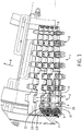
- FIG 1 illustrates an example conveyor 1 including multiple modules 2 that are pivotally coupled to adjacent modules 2 with respective hinge pins 3.
- the hinge pins 3 extend through and are partially captured by alternating cylindrical openings 4 and slotted openings 5, thus allowing the modules 2 to collapse along an inner edge 6 when traversing a lateral curve.
- the modules 2 are supported by, ride along, and are directed by a track 7 as the modules 2 move in a direction of travel 8 (shown in Figure 1 ).
- the modules 2 at the end of each row include a bearing 9 that is rotatably coupled to the module 2.
- the bearing 9 can be any type of bearing (e.g., roller bearing, needle bearing, etc.) that functions to reduce sliding friction, and is shown as a typical ball bearing having balls 10 captured between an inner race 11A and an outer race 11B. While only one bearing 9 is illustrated per row of modules 2, any number of bearings 9 may be incorporated and positioned along the module 2.
- roller bearing e.g., roller bearing, needle bearing, etc.
- ball bearing having balls 10 captured between an inner race 11A and an outer race 11B. While only one bearing 9 is illustrated per row of modules 2, any number of bearings 9 may be incorporated and positioned along the module 2.
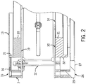
- Figure 2 illustrates the example track 7 supported by a frame 12; the frame 12 supports and spaces apart an upper track 13 and a lower track 14.
- the upper track 13 includes an outer portion 15 having an inwardly extending lip 16 that is configured to help capture the modules 2 to the track 7 during operation of the conveyor 1. Specifically, a tab 18 of the module 2 is captured beneath the lip 16.
- the upper track 13 also includes an inner portion 19 that supports the modules 2 on a horizontal base 20 and has a guide arm 21 that extends upward from the horizontal base 20.
- the guide arm 21 includes an arcuate section matching the curvature of the balance of the track 7.
- the guide arm 21 when the module 2 is installed in the track 7, the guide arm 21 extends upward into a guide channel 22 formed in the module 2, such that the guide arm 21 is positioned between a link end 23 and the bearing 9.
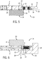
- the guide arm 21 extends upward through a lower plane 24 defined generally along the bottom surface 25 of the module 2 (shown in Figure 5 ).
- the bearing 9 interfaces with the guide arm 21 as the module 2 moves along the track 7. This engagement aids in control of the modules 2 and reduces the drag friction that typically occurs due to the relative sliding movement of the track 7 and the module 2, especially as the modules 2 traverse curves in the track 7.
- the lower track 14 includes an outer portion 26 having an L-shaped cross section, with a horizontal leg 27 that engages a transport surface 28 of the module 2.
- the horizontal leg 27 supports the module 2 as it wraps around the conveyor 1.
- a vertical leg 29 of the outer portion 26 generally shields the side of the modules 2 during operation of the conveyor 1.
- An inner portion 30 has a horizontal base 31 and a guide arm 32 (similar to guide arm 21) that extends downward from the horizontal base 31.
- the guide arm 32 is also arcuate to match the curvature of the track 7.
- the guide arm 32 extends downward into the guide channel 22 formed in the module 2, such that the guide arm 32 is positioned between the link end 23 and the bearing 9.
- the bearing 9 interfaces with the guide arm 32 as the module 2 moves along the track 7.
- this engagement aids in control of the modules 2 and reduces the drag friction that typically occurs due to the relative sliding movement of the track 7 and the module 2.
- the track 7 can be made of plastic, metal, composite material, or any other suitable material having the desired friction and wear characteristics to meet the requirements of a particular application.
- the module 2 can be made of plastic, metal, composite material, or any other suitable material meeting the specific application requirements.
- a variety of conveyor belt modules can be configured to engage a track having some form of guide structure similar to that shown in Figure 2 .
- Four example embodiments are described below and with reference to the respective figures; however, one skilled in the art, given the benefit of this disclosure, will appreciate the various alternative constructions and combinations consistent with the overall inventive concepts.
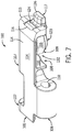
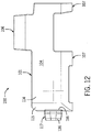
- FIGS 7-14 illustrate a first example module 100.
- the module 100 generally has a body 101 that defines and extends between an upper transport plane 102 and a lower body plane 103 (best shown in Figures 10 , 13, and 14 ).
- the upper transport plane 102 is generally coplanar with a transport surface 104 upon which articles or other module components (e.g., grippers) can be supported or attached.
- the lower body plane 103 is substantially coplanar (with planar surfaces) or tangential (with arcuate surfaces) with the lowermost surfaces 105 of the body, which are generally defined by the lower surfaces of opposing link ends 106, 107.
- the upper transport plane 102 is spaced apart from and generally parallel to the lower body plane 103, and defines a vertical envelope (i.e., the upper and lower bounds/extremes) of the module 100.
- the upper transport plane 102 and the lower body plane 103 need not be substantially parallel, provided the body 101 defines a void 108 for receiving a bearing 109 such that the bearing 109 can be at least partially housed within the void 108, and hence partially within the outer envelope of the module 100.
- the body 101 defines the opposing link ends 106, 107.
- the link end 106 includes a slotted opening 110 allowing the hinge pin to be skewed within the slotted opening 110 (e.g., see hinge pin 3 in Figure 1 ).
- the link ends 107 define a cylindrical opening 111 that is slightly larger than the outer diameter of a respective hinge pin.
- the cylindrical opening 111 defines a hinge axis 112, and the slotted opening 110 defines another hinge axis 113 that is generally defined along the geometric center of the slotted cross section.
- a plane 134 that is defined by the hinge axis 112 and the hinge axis 113 intersects the bearing 109 into two generally equivalent portions, with the lower portion being slightly greater than the upper portion.
- the positioning of the bearing 109 relative to the hinge axes 112, 113 helps to reduce forces and moments imparted to the bearing 109 and the underlying bearing 109 support structure during operation of the module 100 in a conveyor, especially as the module 100 traverses through a curved section of track.
- a bearing is positioned in a body such that a plane defined by hinge axes intersects the bearing, regardless of any defined "void.”
- a cover 114 extends generally from the body 101 in the direction of the hinge axes 112, 113 and establishes bounds of the example void 108 that houses the bearing 109.
- the cover 114 also defines a downturned end wall 115 having a notched opening 116 that is configured to receive a tab 117, that is, a portion of the tab 117 can extend through the notched opening 116 into the void 108.
- the example module 100 includes a post 118 having a generally cylindrical form factor that is formed integral with the cover 114.
- the post 118 extends from an underside 119 of the cover 114 along a post axis 120 to a tip 121.
- the post 118 is oriented substantially perpendicular to the underside 119 of the cover 114 and generally transverse to the hinge axes 112, 113. In other forms, the relative orientation between the post 118 and the cover 114 may be skewed.
- the tab 117 of the example module 100 is configured to both engage the bearing 109 and the post 118.
- the tab 117 includes an upper arm 122 and a lower arm 123 that are connected by an intermediate bridge portion 124.
- the upper arm 122 defines an upper opening 125 and the lower arm 123 similarly defines a lower opening 126; the upper opening 125 and the lower opening 126 are coaxial and are sized to receive the post 118.
- the bearing 109 Before the tab 117 is slid over the post 118, the bearing 109 is inserted between the upper arm 122 and the lower arm 123, thus sandwiching the bearing 109. With a central opening 127 of the bearing 109 positioned coaxial with the upper opening 125 and the lower opening 126, the bearing 109 and the tab 117 are engaged with (i.e., slid onto) the post 118.
- the tab 117 e.g., the thickness of the upper arm 122 and the lower arm 123 helps position the bearing 109 relative to the balance of the module 100 to orient the bearing 109 in a desired location (e.g., such that the plane 134 intersects the bearing 109) to reduce excessive stresses on both the bearing 109 and the supporting post 118.
- a fastener 128 is engaged with the post 118 to capture the bearing 109 between the cover 114 and the fastener 128.
- the example fastener 128 includes a barbed shank portion 129 that extends from an enlarged flange portion 130.
- the barbed shank portion 129 includes surface contours that axially interlock with a cooperating structure in a receptacle 131 (e.g., a generally cylindrical cavity with axially spaced, annular ribs shown in Figure 5 ) formed in the post 118 (best shown in Figure 9 ), which inhibits translation of the fastener 128 along the post axis 120. Inserting the barbed shank portion 129 into the receptacle 131 results in the enlarged flange portion 130 abutting the lower arm 123 of the tab 117, and thus capturing the tab 117 and the bearing 109 to the post 118.
- a receptacle 131 e.g., a generally cylindrical cavity with axially spaced, annular ribs shown in Figure 5
- Inserting the barbed shank portion 129 into the receptacle 131 results in the enlarged flange portion 130 abutting the lower arm 123 of the tab 117, and thus capturing the tab 117 and the bearing
- a guide channel 132 is established between a side face 135 of the link end 107 and a cylindrical engagement surface 133 of the bearing 109.
- the bearing 109 interfaces with a guide arm as the module 100 moves along the track (e.g., as shown with reference to Figure 1 ).
- the cylindrical engagement surface 133 rolls against a tangentially oriented guide surface defined by the guide arm of the track. This engagement aids in control of the modules 100 and reduces the drag friction that typically occurs due to the relative sliding movement of the track and the module 100.
- the tab 117 further includes a guide 136 that extends from the bridge portion 124 in the direction of the hinge axes 112, 113.
- the guide 136 is configured to be partially captured by a cooperating track, similar to the tab 18 shown best in Figure 5 .
- the bearing 109 in the example module 100 is completely housed between the upper transport plane 102 and the lower body plane 103 defined by the body 101. While the bearing 109 need not be completely housed between the planes 102, 103, in some constructions, at least partially positioning the bearing 109 between the upper transport plane 102 and the lower body plane 103 allows the plane 134 (illustrated as a line in Figures 10 and 13 ), which is defined by the hinge axis 112 and the hinge axis 113 (and generally parallel to the planes 102, 103 in the example module 100), to intersect the bearing 109 defining two portions, which are preferably generally equivalent halves. Furthermore, in the example embodiment, the bearing 109 is also completely beneath the cover 114 (as viewed in Figure 12 ), but may extend beyond the cover 114 in other embodiments.
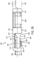
- FIGS 15-19 illustrate a second example module 200.
- the module 200 has a body 201 that defines and extends between an upper plane 202 and a lower plane 203.
- the upper plane 202 is spaced apart from the lower plane 203 to define a thickness of the module 200 between which a bearing 204 is (at least partially) housed.
- the bearing 204 is completely housed within the thickness of the module 200 in a void 205 defined by the body 201.
- the body 201 includes opposing link ends 206, 207 with respective openings 208, 209 for receiving mating hinge pins during operation. Each opening 208, 209 further defines a respective hinge axis 210, 211, and a plane 212 is then established by the hinge axes 210, 211. As best shown in Figure 18 , the plane 212 intersects the bearing 204 to define two portions. Again, the location of the bearing 204 relative to the hinge axes 210, 211 reduces the forces and moments imparted to the bearing 204 and the underlying support structure during operation of the module 200 in a conveyor, especially as the module 200 traverses through a curved section of track.
- a cover 213 extends from the body 201 and establishes bounds of the example void 205 that houses the bearing 204.
- the cover 213 also defines a downturned end wall 214 having an opening 215 that is configured to receive a tab 216, that is, a portion of the tab 216 can extend through the opening 215 into the void 205.
- the example module 200 includes a post 217 having a generally cylindrical form factor that is integral with the cover 213, and that extends from the cover 213 along a post axis 218 to a tip 219.
- the post 217 includes an annular groove 220 near the tip 219 that is sized to receive a fastener in the form of a retaining ring 221, which when seated in the annular groove 220 captures the bearing 204 to the post 217 to inhibit the bearing 204 from moving along the post axis 218.
- the tab 216 of the example module 200 is configured to both engage the bearing 204 and the post 217.
- the tab 216 includes an arm 222 having opposing resilient fingers 223, 224 that can be secured to the post 217.
- the resilient fingers 223, 224 define a generally circular C-shaped opening 225 that is sized to engage the outer diameter of the post 217.
- the resilient fingers 223, 224 are inserted through the opening 215 in the end wall 214 and flex to allow the post 217 to seat into the opening 225. With the tab 216 secured to the post 217, a central opening 226 of the bearing 204 is aligned and slid over the post 217.
- the retaining ring 221 is then seated in the annular groove 220 to capture the bearing 204 to the post 217.
- the tab 216 e.g., the thickness of the arm 222 helps position the bearing 204 within the module 200 to orient the bearing 204 in a desired location to reduce excessive stresses on both the bearing 204 and the supporting post 217 (best shown in Figure 18 ).
- a guide channel 227 is established between a side face 228 of the link end 207 and the bearing 204.
- the bearing 204 interfaces with a guide arm as the module 200 moves along the track (e.g., as shown with reference to Figure 1 ).
- This engagement aids in control of the modules 200 and reduces the drag friction that typically occurs due to the relative sliding movement of the track and the module 200.
- the bearing 204 in the example module 200 is also completely housed between the upper plane 202 and the lower plane 203, and is also completely within the void 205 (e.g., the bearing 204 is shown completely beneath the cover 213 in Figure 19 ).
- the bearing 204 need not be completely housed between the planes 202, 203, in some forms, at least partially positioning the bearing 204 between the upper plane 202 and the lower plane 203 allows the plane 212 (illustrated as a line in Figure 18 ) defined by the hinge axis 210 and the hinge axis 211 to intersect the bearing 204, which reduces operating stresses on the bearing 204.
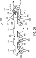
- FIGS 20-24 illustrate a third example module 300.
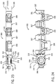
- the module 300 has a body 301 that defines and extends between an upper plane 302 and a lower plane 303 (shown in Figure 23 ).
- the upper plane 302 is spaced apart from the lower plane 303 to establish an envelope between which a bearing 304 is housed.
- the bearing 304 is completely housed within the thickness of the module 300 in a void 305 defined by the body 301.
- the body 301 includes opposing link ends 306, 307 with respective openings 308, 309 for receiving mating hinge pins during operation; each opening 308, 309 further defines a respective hinge axis 310, 311.
- a plane 312 is defined by the hinge axes 310, 311 such that both hinge axes 310, 311 are substantially on the plane 312. As best shown in Figure 23 , the plane 312 intersects the bearing 304, defining a lower portion that is greater than an upper portion. In some forms, the lower portion is about equal to the upper portion. Again, the location of the bearing 304 relative to the hinge axes 310, 311 reduces the forces and moments imparted to the bearing 304 and the support structure during operation of the module 300.
- a cover 313 extends from the body 301 and establishes bounds of the void 305 that houses the bearing 304.
- the cover 313 also defines a downturned end wall 314 having an opening 315 that is configured to receive a tab 316, that is, a portion of the tab 316 can extend through the opening 315 into the void 305.
- the example module 300 includes a post 317 having a generally cylindrical form factor that is integral with the cover 313, and that extends from the cover 313 along a post axis 318. As with the other embodiments, the post 317 is sized to receive the bearing 304.
- the tab 316 of the example module 300 is configured to both engage the bearing 304 and the post 317.
- the tab 316 includes an arm 322 having opposing resilient fingers 323, 324 that can be secured to the post 317.
- the resilient fingers 323, 324 define a generally circular C-shaped opening 325 that is sized to engage the outer diameter of the post 317.
- the resilient fingers 323, 324 are inserted through the opening 315 in the end wall 314 and flex to allow the post 317 to seat into the opening 325.
- a central opening 326 of the bearing 304 is aligned and slid over the post 317.
- the tab 316 (e.g., the thickness of the arm 322) helps position the bearing 304 within the module 300 to orient the bearing 304 in a desired location to reduce excessive stresses on both the bearing 304 and the supporting post 317 (best shown in Figure 23 ).
- a fastener in the form of a rivet 332 is engaged with the post 317 to capture the bearing 304 between the cover 313 and the rivet 332.
- the example rivet 332 includes a shank portion 327 that extends from an enlarged flange portion 328.
- An opening 329 is formed through the post 317 (best shown in Figures 21 and 22 ) and is sized to receive the shank portion 327 of the rivet 332.
- the enlarged flange portion 328 supports the bearing 304 when assembled to the balance of the module 300. Specifically, inserting the shank portion 327 into the opening 329 engages the enlarged flange portion 328 with the bearing 304.
- a tip 331 of the shank portion 327 extends from the opening 329 near the cover 313 where it is deformed to capture the rivet 332 to the cover 313, thus inhibiting translation of the rivet 332 along the post axis 318 and capturing the bearing 304 to the post 317.
- a guide channel 333 is established between a side face 334 of the link end 307 and the bearing 304.
- the bearing 304 interfaces with a guide arm as the module 300 moves along the track (e.g., as shown with reference to Figure 1 ). This engagement aids in control of the modules 300 and reduces the drag friction that typically occurs due to the relative sliding movement of the track and the module 300.
- the bearing 304 in the example module 300 is also completely housed between the upper plane 302 and the lower plane 303, and is also completely within the void 305 (e.g., the bearing 304 is shown completely beneath the cover 313 in Figure 24 ).
- the bearing 304 need not be completely housed between the planes 302, 303 (or completely beneath the cover 313), at least partially positioning the bearing 304 between the planes 302, 303 allows the plane 312 (illustrated as a line in Figure 23 ) to intersect the bearing 304, which can ultimately reduce stress on the post 317.
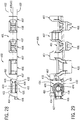
- FIGs 25-29 illustrate a fourth example module 400.
- the module 400 has a body 401 that is bounded vertically (with reference to Figure 28 ) between an upper plane 402 and a lower plane 403, which is spaced apart from and generally parallel to the upper plane 402.
- the body 401 defines a void 404 for receiving a bearing 405, such that the bearing 405 can be at least partially housed within the void 404, and as shown, not extend downward beyond the lower plane 403.
- Opposing link ends 406, 407 extend from the body 401 and, in use, are engaged via hinge pins to couple adjacent modules 400.
- the link ends 406 include a slotted opening 408 that defines a hinge axis 409 and the link ends 407 include a circular opening 410 that defines a hinge axis 411.
- a plane 412 on which both the hinge axes 409, 411 are positioned intersects the bearing 405 to define an upper portion and a lower portion of the bearing 405.
- the positioning of the bearing 405 relative to the hinge axes 409, 411 helps to reduce forces and moments imparted to and transferred by the bearing 405, especially as the module 400 traverses a curved segment of a track.
- a cover 413 extends laterally from the balance of the body 401 and establishes bounds of the void 404 that houses the bearing 405.
- the cover 413 also defines a downturned end wall 414 having a recessed slot 415 that is configured to receive a tab 416, that is, a portion of the tab 416 can extend partially through the slot 415 and into the void 404.
- the cover 413 also defines a countersunk opening 417 that is configured to receive a post 418, which is separate from the cover 413.
- the generally cylindrical post 418 includes a shank portion 419 extending from an enlarged flange portion 420. Inserting the shank portion 419 downward through the countersunk opening 417 allows the enlarged flange portion 420 to seat in a countersink 421 formed in the cover 413, such that the enlarged flange portion 420 abuts the cover 413.
- the lower end 422 of the shank portion 419 includes an annular groove 423 that is engaged by a fastener in the form of a retaining ring 424, which when seated in the annular groove 423 captures the bearing 405 to the post 418 to inhibit the bearing 405 from moving along a post axis 425.
- the tab 416 is again configured to both engage the bearing 405 and the post 418.
- the tab 416 includes an upper arm 426 and a lower arm 427 that are connected by an intermediate bridge portion 434.
- the upper arm 426 defines an upper opening 428 and the lower arm 427 defines a lower opening 429 that is coaxial with the upper opening 428.
- the upper opening 428 and the lower opening 429 are sized to receive the post 418.
- the upper arm 426 of the tab 416 is inserted through the recessed slot 415 in the end wall 414.
- the bearing 405 is then inserted between the upper arm 426 and the lower arm 427, thus sandwiching the bearing 405.
- the post 418 is inserted through the opening 417 in the cover 413 until the enlarged flange portion 420 seats in the countersink 421.
- the retaining ring 424 is finally secured in the annular groove 423 to capture the bearing 405 to the post 418, which also inhibits the post 418 from being removed from the opening 417 in the cover 413.
- the tab 416 e.g., the thickness of the upper arm 426 and the lower arm 427) helps position the bearing 405 relative to the balance of the module 400 to orient the bearing 405 to reduce excessive stresses on the bearing 405.
- a guide channel 431 is established between a side face 432 of the link end 407 and a cylindrical engagement surface 433 of the bearing 405.
- the bearing 405 interfaces with a guide arm as the module 400 moves along the track (e.g., as shown with reference to Figure 1 ).
- the cylindrical engagement surface 433 rolls against a tangentially oriented guide surface defined by the guide arm of the track to both aid the control of the modules 400 and to reduce the drag friction that typically occurs due to the relative sliding movement of the track and the module 400.
- the bearing 405 in the example module 400 is completely housed within the upper plane 402 and the lower plane 403 to reduce the stresses transferred from the bearing 405 to the post 418 and the balance of the module. Furthermore, the bearing 405 is also completely within the void 404 (e.g., the bearing 405 is shown completely beneath the cover 413 in Figure 29 ).
- the fastener may be a resilient, snap-fit structure integrally formed with a distal tip of a post, such that installing a bearing to the post radially compresses a splayed tip of the post, which allows the bearing to be mounted. The splayed tip then rebounds radially outward to axially capture the bearing to the post.
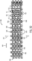
- FIGS 30-32 illustrate a portion of a conveyor belt 500 having a series of modules 501 according to the invention linked together to form the conveyor belt 500.
- the modules 501 are configured to inhibit erroneous engagement with a drive member (e.g., a drive sprocket) by limiting the available drive surfaces, while allowing the modules 501 to collapse as the pitch between successive hinge pins is reduced when traversing a curve.
- a drive member e.g., a drive sprocket
- Each module 501 includes a central web 502 extending in a lateral direction 503 (i.e., side-to-side as shown in Figure 30 ).
- a series of first link ends 504 extend from the web 502 in a first direction 505 that is transverse to the lateral direction 503.
- a series of second link ends 506 also extend from the web 502 in a second direction 507 that is opposite to the first direction 505.
- a series of drive pockets 508 are defined by a drive surface 509 (shown in Figure 30 ) of the first link ends 504.
- a drive sprocket is aligned with the successive drive pockets 508 of adjacent modules 501 and drives movement of the conveyor belt 500.
- the second link ends 506 include a central protrusion 510 that extends in the first direction 505.
- a pair of laterally spaced protrusions 511, 512 extend in the second direction 507 and are spaced laterally from an adjacent, central protrusion 510.
- the central protrusion 510 will move between the pair of spaced protrusions 511, 512 of an adjacent module 501.
- the protrusions 510, 511, 512 substantially encroach into the space between successive modules 501 that can be erroneously equated to the designed drive pockets 508, thereby inhibiting a tooth of a drive sprocket from fitting between and erroneously engaging the second link ends 506.
- the protrusions may be greater or fewer in number and may take on a variety of form factors.
Landscapes
- Engineering & Computer Science (AREA)
- Mechanical Engineering (AREA)
- Chain Conveyers (AREA)
Applications Claiming Priority (2)
| Application Number | Priority Date | Filing Date | Title |
|---|---|---|---|
| US201261652936P | 2012-05-30 | 2012-05-30 | |
| EP13729552.3A EP2855308B1 (en) | 2012-05-30 | 2013-05-30 | Conveyor belt module with bearing retainer |
Related Parent Applications (2)
| Application Number | Title | Priority Date | Filing Date |
|---|---|---|---|
| EP13729552.3A Division-Into EP2855308B1 (en) | 2012-05-30 | 2013-05-30 | Conveyor belt module with bearing retainer |
| EP13729552.3A Division EP2855308B1 (en) | 2012-05-30 | 2013-05-30 | Conveyor belt module with bearing retainer |
Publications (2)
| Publication Number | Publication Date |
|---|---|
| EP2962963A1 EP2962963A1 (en) | 2016-01-06 |
| EP2962963B1 true EP2962963B1 (en) | 2017-01-25 |
Family
ID=48628933
Family Applications (2)
| Application Number | Title | Priority Date | Filing Date |
|---|---|---|---|
| EP15179935.0A Active EP2962963B1 (en) | 2012-05-30 | 2013-05-30 | Conveyor belt module with bearing retainer |
| EP13729552.3A Not-in-force EP2855308B1 (en) | 2012-05-30 | 2013-05-30 | Conveyor belt module with bearing retainer |
Family Applications After (1)
| Application Number | Title | Priority Date | Filing Date |
|---|---|---|---|
| EP13729552.3A Not-in-force EP2855308B1 (en) | 2012-05-30 | 2013-05-30 | Conveyor belt module with bearing retainer |
Country Status (11)
| Country | Link |
|---|---|
| US (1) | US9327905B2 (pl) |
| EP (2) | EP2962963B1 (pl) |
| CN (1) | CN104507831B (pl) |
| AU (1) | AU2013267360B2 (pl) |
| BR (1) | BR112014029842B1 (pl) |
| CA (1) | CA2874849C (pl) |
| DK (1) | DK2962963T3 (pl) |
| ES (1) | ES2622994T3 (pl) |
| IN (1) | IN2014KN02751A (pl) |
| MX (1) | MX346479B (pl) |
| WO (1) | WO2013181354A1 (pl) |
Families Citing this family (6)
| Publication number | Priority date | Publication date | Assignee | Title |
|---|---|---|---|---|
| DE102015214746B4 (de) | 2015-08-03 | 2024-05-29 | Krones Aktiengesellschaft | Horizontalförderabschnitt mit in Kurve geführter Mattenkette zur Beförderung von Artikeln oder Stückgütern |
| US10752446B2 (en) | 2015-09-25 | 2020-08-25 | Habasit Ag | Hybrid modular belt |
| NL2015696B1 (en) * | 2015-10-30 | 2017-05-31 | Rexnord Flattop Europe Bv | Chain module, modular conveyor chain, and conveyor system. |
| US10947048B2 (en) * | 2017-07-12 | 2021-03-16 | Habasit Ag | Positive drive for a spiral conveyor and belt module for a radius or spiral conveyor |
| CN111874527A (zh) * | 2020-07-01 | 2020-11-03 | 深圳市华南新海传动机械有限公司 | 一种低噪声低振动的输送带模块 |
| IT202200014914A1 (it) | 2022-07-15 | 2024-01-15 | Regina Catene Calibrate Spa | Modulo di tappeto trasportatore modulare curvilineo a raggio fisso e corrispondente tappeto. |
Family Cites Families (15)
| Publication number | Priority date | Publication date | Assignee | Title |
|---|---|---|---|---|
| US5076422A (en) * | 1990-08-29 | 1991-12-31 | Tekno Incorporated | Side-flexing chain with wheels |
| DE4324120A1 (de) * | 1993-07-19 | 1995-01-26 | Hauni Werke Koerber & Co Kg | Förderkette |
| DK50694A (da) | 1994-05-03 | 1995-11-04 | Baeltix Maskinfabrikken As | Transportørkæde |
| US5573105A (en) * | 1995-11-08 | 1996-11-12 | Palmaer; Karl V. | Radius conveyor with guide rollers |
| US5775480A (en) * | 1996-06-14 | 1998-07-07 | The Laitram Corporation | Low-friction conveyor assembly |
| US5906270A (en) * | 1996-08-16 | 1999-05-25 | Faulkner; William G. | Tight turning radius conveyor belt |
| US6216851B1 (en) * | 1998-10-22 | 2001-04-17 | Flexible Steel Lacing Company | Rivet belt fastener |
| EP1260459A1 (en) | 2001-05-16 | 2002-11-27 | uni-chains A/S | Side-flexing conveyor belt |
| DK1614644T3 (da) | 2004-07-06 | 2007-06-04 | Laitram Llc | Transportbånd og transportbåndmodul med en selvjusterende kant |
| US7070043B1 (en) * | 2005-06-08 | 2006-07-04 | Laitram, L.L.C. | Modular plastic conveyor belt suitable for tight turns |
| US7252192B2 (en) | 2005-07-01 | 2007-08-07 | Rexnord Industries, Llc | Side-flexing conveyor module with detachable roller assembly |
| US20090199375A1 (en) * | 2006-01-20 | 2009-08-13 | Fred Koelling | Latching system |
| ITMI20080345A1 (it) * | 2008-02-29 | 2009-09-01 | Regina Catene Calibrate Spa | "tappeto trasportatore con mezzi di guida per percorsi curvilinei e moduli per esso" |
| MX2011004822A (es) * | 2008-11-07 | 2011-05-30 | Laitram Llc | Banda en espiral plastica modular. |
| FR2969481B1 (fr) * | 2010-12-28 | 2013-11-29 | H 32 | Ensemble attache-clip-base avec base pour appareillage orthodontique et appareil orthodontique le comportant. |
-
2013
- 2013-05-30 MX MX2014014518A patent/MX346479B/es active IP Right Grant
- 2013-05-30 AU AU2013267360A patent/AU2013267360B2/en not_active Ceased
- 2013-05-30 EP EP15179935.0A patent/EP2962963B1/en active Active
- 2013-05-30 BR BR112014029842-4A patent/BR112014029842B1/pt not_active IP Right Cessation
- 2013-05-30 EP EP13729552.3A patent/EP2855308B1/en not_active Not-in-force
- 2013-05-30 CA CA2874849A patent/CA2874849C/en active Active
- 2013-05-30 IN IN2751KON2014 patent/IN2014KN02751A/en unknown
- 2013-05-30 CN CN201380040339.8A patent/CN104507831B/zh not_active Expired - Fee Related
- 2013-05-30 US US13/905,378 patent/US9327905B2/en active Active
- 2013-05-30 WO PCT/US2013/043291 patent/WO2013181354A1/en not_active Ceased
- 2013-05-30 DK DK15179935.0T patent/DK2962963T3/en active
- 2013-05-30 ES ES15179935.0T patent/ES2622994T3/es active Active
Non-Patent Citations (1)
| Title |
|---|
| None * |
Also Published As
| Publication number | Publication date |
|---|---|
| US9327905B2 (en) | 2016-05-03 |
| AU2013267360A1 (en) | 2014-12-18 |
| IN2014KN02751A (pl) | 2015-05-08 |
| DK2962963T3 (en) | 2017-05-01 |
| EP2855308B1 (en) | 2016-09-28 |
| CA2874849A1 (en) | 2013-12-05 |
| CN104507831A (zh) | 2015-04-08 |
| WO2013181354A1 (en) | 2013-12-05 |
| CN104507831B (zh) | 2016-08-24 |
| CA2874849C (en) | 2021-03-02 |
| MX2014014518A (es) | 2015-04-08 |
| US20130319829A1 (en) | 2013-12-05 |
| BR112014029842B1 (pt) | 2020-12-08 |
| HK1208852A1 (en) | 2016-03-18 |
| EP2855308A1 (en) | 2015-04-08 |
| AU2013267360B2 (en) | 2017-06-15 |
| MX346479B (es) | 2017-03-22 |
| ES2622994T3 (es) | 2017-07-10 |
| EP2962963A1 (en) | 2016-01-06 |
| HK1219261A1 (en) | 2017-03-31 |
| BR112014029842A2 (pt) | 2017-06-27 |
Similar Documents
| Publication | Publication Date | Title |
|---|---|---|
| CA2874849C (en) | Conveyor belt module with bearing retainer | |
| US8366215B2 (en) | Stabilizing assembly of drawable carrier | |
| KR101237315B1 (ko) | 반송설비 | |
| US7798717B2 (en) | Spacer | |
| US7004310B2 (en) | Belt band conveyor having separate guide shoes | |
| US8397903B2 (en) | Modular belt conveyor, in particular a curving or helical conveyor | |
| US9731898B2 (en) | Slat for a conveyor | |
| CN104411604B (zh) | 传送器链节、传送器链、驱动轮以及传送器系统 | |
| US20100175969A1 (en) | Conveyor | |
| HK1219261B (en) | Conveyor belt module with bearing retainer | |
| US11566685B2 (en) | Line guiding system and guide trough, in particular for high displacement speeds | |
| JP7414341B2 (ja) | チェーンコンベア装置 | |
| EP2794437B1 (en) | Detachable tab for a modular belt link | |
| CN102431873A (zh) | 乘客输送机 | |
| EP1704109B1 (en) | Device for restraining the rise of a step roller of a people conveyor | |
| HK1208852B (en) | Conveyor belt module with bearing retainer | |
| US7506744B2 (en) | Changeover system | |
| US20110315508A1 (en) | Modular chain newel with standard bearing | |
| JPH0530590U (ja) | 高負荷伝動用ベルト | |
| CN215556447U (zh) | 吸塑生产线及输送装置 | |
| EP0327868A2 (en) | Pin belt for movement of perforated strip | |
| JP2018167932A (ja) | コンベヤ用ガイド形成部材、並びに、コンベヤ装置 |
Legal Events
| Date | Code | Title | Description |
|---|---|---|---|
| PUAI | Public reference made under article 153(3) epc to a published international application that has entered the european phase |
Free format text: ORIGINAL CODE: 0009012 |
|
| 17P | Request for examination filed |
Effective date: 20150806 |
|
| AC | Divisional application: reference to earlier application |
Ref document number: 2855308 Country of ref document: EP Kind code of ref document: P |
|
| AK | Designated contracting states |
Kind code of ref document: A1 Designated state(s): AL AT BE BG CH CY CZ DE DK EE ES FI FR GB GR HR HU IE IS IT LI LT LU LV MC MK MT NL NO PL PT RO RS SE SI SK SM TR |
|
| GRAP | Despatch of communication of intention to grant a patent |
Free format text: ORIGINAL CODE: EPIDOSNIGR1 |
|
| INTG | Intention to grant announced |
Effective date: 20160808 |
|
| GRAS | Grant fee paid |
Free format text: ORIGINAL CODE: EPIDOSNIGR3 |
|
| GRAA | (expected) grant |
Free format text: ORIGINAL CODE: 0009210 |
|
| AC | Divisional application: reference to earlier application |
Ref document number: 2855308 Country of ref document: EP Kind code of ref document: P |
|
| AK | Designated contracting states |
Kind code of ref document: B1 Designated state(s): AL AT BE BG CH CY CZ DE DK EE ES FI FR GB GR HR HU IE IS IT LI LT LU LV MC MK MT NL NO PL PT RO RS SE SI SK SM TR |
|
| REG | Reference to a national code |
Ref country code: GB Ref legal event code: FG4D |
|
| REG | Reference to a national code |
Ref country code: CH Ref legal event code: EP |
|
| REG | Reference to a national code |
Ref country code: AT Ref legal event code: REF Ref document number: 863968 Country of ref document: AT Kind code of ref document: T Effective date: 20170215 |
|
| REG | Reference to a national code |
Ref country code: IE Ref legal event code: FG4D |
|
| REG | Reference to a national code |
Ref country code: DE Ref legal event code: R096 Ref document number: 602013016891 Country of ref document: DE |
|
| REG | Reference to a national code |
Ref country code: HK Ref legal event code: DE Ref document number: 1219261 Country of ref document: HK |
|
| REG | Reference to a national code |
Ref country code: DK Ref legal event code: T3 Effective date: 20170427 |
|
| REG | Reference to a national code |
Ref country code: NL Ref legal event code: FP |
|
| REG | Reference to a national code |
Ref country code: FR Ref legal event code: PLFP Year of fee payment: 5 |
|
| REG | Reference to a national code |
Ref country code: LT Ref legal event code: MG4D |
|
| REG | Reference to a national code |
Ref country code: AT Ref legal event code: MK05 Ref document number: 863968 Country of ref document: AT Kind code of ref document: T Effective date: 20170125 |
|
| REG | Reference to a national code |
Ref country code: ES Ref legal event code: FG2A Ref document number: 2622994 Country of ref document: ES Kind code of ref document: T3 Effective date: 20170710 |
|
| PG25 | Lapsed in a contracting state [announced via postgrant information from national office to epo] |
Ref country code: NO Free format text: LAPSE BECAUSE OF FAILURE TO SUBMIT A TRANSLATION OF THE DESCRIPTION OR TO PAY THE FEE WITHIN THE PRESCRIBED TIME-LIMIT Effective date: 20170425 Ref country code: LT Free format text: LAPSE BECAUSE OF FAILURE TO SUBMIT A TRANSLATION OF THE DESCRIPTION OR TO PAY THE FEE WITHIN THE PRESCRIBED TIME-LIMIT Effective date: 20170125 Ref country code: HR Free format text: LAPSE BECAUSE OF FAILURE TO SUBMIT A TRANSLATION OF THE DESCRIPTION OR TO PAY THE FEE WITHIN THE PRESCRIBED TIME-LIMIT Effective date: 20170125 Ref country code: GR Free format text: LAPSE BECAUSE OF FAILURE TO SUBMIT A TRANSLATION OF THE DESCRIPTION OR TO PAY THE FEE WITHIN THE PRESCRIBED TIME-LIMIT Effective date: 20170426 Ref country code: FI Free format text: LAPSE BECAUSE OF FAILURE TO SUBMIT A TRANSLATION OF THE DESCRIPTION OR TO PAY THE FEE WITHIN THE PRESCRIBED TIME-LIMIT Effective date: 20170125 Ref country code: IS Free format text: LAPSE BECAUSE OF FAILURE TO SUBMIT A TRANSLATION OF THE DESCRIPTION OR TO PAY THE FEE WITHIN THE PRESCRIBED TIME-LIMIT Effective date: 20170525 |
|
| PG25 | Lapsed in a contracting state [announced via postgrant information from national office to epo] |
Ref country code: LU Free format text: LAPSE BECAUSE OF NON-PAYMENT OF DUE FEES Effective date: 20170531 Ref country code: PT Free format text: LAPSE BECAUSE OF FAILURE TO SUBMIT A TRANSLATION OF THE DESCRIPTION OR TO PAY THE FEE WITHIN THE PRESCRIBED TIME-LIMIT Effective date: 20170525 Ref country code: SE Free format text: LAPSE BECAUSE OF FAILURE TO SUBMIT A TRANSLATION OF THE DESCRIPTION OR TO PAY THE FEE WITHIN THE PRESCRIBED TIME-LIMIT Effective date: 20170125 Ref country code: RS Free format text: LAPSE BECAUSE OF FAILURE TO SUBMIT A TRANSLATION OF THE DESCRIPTION OR TO PAY THE FEE WITHIN THE PRESCRIBED TIME-LIMIT Effective date: 20170125 Ref country code: AT Free format text: LAPSE BECAUSE OF FAILURE TO SUBMIT A TRANSLATION OF THE DESCRIPTION OR TO PAY THE FEE WITHIN THE PRESCRIBED TIME-LIMIT Effective date: 20170125 Ref country code: BG Free format text: LAPSE BECAUSE OF FAILURE TO SUBMIT A TRANSLATION OF THE DESCRIPTION OR TO PAY THE FEE WITHIN THE PRESCRIBED TIME-LIMIT Effective date: 20170425 Ref country code: PL Free format text: LAPSE BECAUSE OF FAILURE TO SUBMIT A TRANSLATION OF THE DESCRIPTION OR TO PAY THE FEE WITHIN THE PRESCRIBED TIME-LIMIT Effective date: 20170125 Ref country code: LV Free format text: LAPSE BECAUSE OF FAILURE TO SUBMIT A TRANSLATION OF THE DESCRIPTION OR TO PAY THE FEE WITHIN THE PRESCRIBED TIME-LIMIT Effective date: 20170125 |
|
| REG | Reference to a national code |
Ref country code: DE Ref legal event code: R097 Ref document number: 602013016891 Country of ref document: DE |
|
| PG25 | Lapsed in a contracting state [announced via postgrant information from national office to epo] |
Ref country code: EE Free format text: LAPSE BECAUSE OF FAILURE TO SUBMIT A TRANSLATION OF THE DESCRIPTION OR TO PAY THE FEE WITHIN THE PRESCRIBED TIME-LIMIT Effective date: 20170125 Ref country code: CZ Free format text: LAPSE BECAUSE OF FAILURE TO SUBMIT A TRANSLATION OF THE DESCRIPTION OR TO PAY THE FEE WITHIN THE PRESCRIBED TIME-LIMIT Effective date: 20170125 Ref country code: RO Free format text: LAPSE BECAUSE OF FAILURE TO SUBMIT A TRANSLATION OF THE DESCRIPTION OR TO PAY THE FEE WITHIN THE PRESCRIBED TIME-LIMIT Effective date: 20170125 Ref country code: SK Free format text: LAPSE BECAUSE OF FAILURE TO SUBMIT A TRANSLATION OF THE DESCRIPTION OR TO PAY THE FEE WITHIN THE PRESCRIBED TIME-LIMIT Effective date: 20170125 |
|
| PG25 | Lapsed in a contracting state [announced via postgrant information from national office to epo] |
Ref country code: SM Free format text: LAPSE BECAUSE OF FAILURE TO SUBMIT A TRANSLATION OF THE DESCRIPTION OR TO PAY THE FEE WITHIN THE PRESCRIBED TIME-LIMIT Effective date: 20170125 |
|
| PLBE | No opposition filed within time limit |
Free format text: ORIGINAL CODE: 0009261 |
|
| STAA | Information on the status of an ep patent application or granted ep patent |
Free format text: STATUS: NO OPPOSITION FILED WITHIN TIME LIMIT |
|
| 26N | No opposition filed |
Effective date: 20171026 |
|
| PG25 | Lapsed in a contracting state [announced via postgrant information from national office to epo] |
Ref country code: MC Free format text: LAPSE BECAUSE OF FAILURE TO SUBMIT A TRANSLATION OF THE DESCRIPTION OR TO PAY THE FEE WITHIN THE PRESCRIBED TIME-LIMIT Effective date: 20170125 |
|
| REG | Reference to a national code |
Ref country code: IE Ref legal event code: MM4A |
|
| PG25 | Lapsed in a contracting state [announced via postgrant information from national office to epo] |
Ref country code: SI Free format text: LAPSE BECAUSE OF FAILURE TO SUBMIT A TRANSLATION OF THE DESCRIPTION OR TO PAY THE FEE WITHIN THE PRESCRIBED TIME-LIMIT Effective date: 20170125 |
|
| PG25 | Lapsed in a contracting state [announced via postgrant information from national office to epo] |
Ref country code: LU Free format text: LAPSE BECAUSE OF NON-PAYMENT OF DUE FEES Effective date: 20170530 |
|
| REG | Reference to a national code |
Ref country code: BE Ref legal event code: MM Effective date: 20170531 |
|
| REG | Reference to a national code |
Ref country code: HK Ref legal event code: GR Ref document number: 1219261 Country of ref document: HK |
|
| PG25 | Lapsed in a contracting state [announced via postgrant information from national office to epo] |
Ref country code: IE Free format text: LAPSE BECAUSE OF NON-PAYMENT OF DUE FEES Effective date: 20170530 |
|
| REG | Reference to a national code |
Ref country code: FR Ref legal event code: PLFP Year of fee payment: 6 |
|
| PG25 | Lapsed in a contracting state [announced via postgrant information from national office to epo] |
Ref country code: BE Free format text: LAPSE BECAUSE OF NON-PAYMENT OF DUE FEES Effective date: 20170531 |
|
| PG25 | Lapsed in a contracting state [announced via postgrant information from national office to epo] |
Ref country code: MT Free format text: LAPSE BECAUSE OF NON-PAYMENT OF DUE FEES Effective date: 20170530 |
|
| PG25 | Lapsed in a contracting state [announced via postgrant information from national office to epo] |
Ref country code: HU Free format text: LAPSE BECAUSE OF FAILURE TO SUBMIT A TRANSLATION OF THE DESCRIPTION OR TO PAY THE FEE WITHIN THE PRESCRIBED TIME-LIMIT; INVALID AB INITIO Effective date: 20130530 |
|
| PG25 | Lapsed in a contracting state [announced via postgrant information from national office to epo] |
Ref country code: CY Free format text: LAPSE BECAUSE OF FAILURE TO SUBMIT A TRANSLATION OF THE DESCRIPTION OR TO PAY THE FEE WITHIN THE PRESCRIBED TIME-LIMIT Effective date: 20170125 |
|
| PG25 | Lapsed in a contracting state [announced via postgrant information from national office to epo] |
Ref country code: MK Free format text: LAPSE BECAUSE OF FAILURE TO SUBMIT A TRANSLATION OF THE DESCRIPTION OR TO PAY THE FEE WITHIN THE PRESCRIBED TIME-LIMIT Effective date: 20170125 |
|
| PG25 | Lapsed in a contracting state [announced via postgrant information from national office to epo] |
Ref country code: TR Free format text: LAPSE BECAUSE OF FAILURE TO SUBMIT A TRANSLATION OF THE DESCRIPTION OR TO PAY THE FEE WITHIN THE PRESCRIBED TIME-LIMIT Effective date: 20170125 |
|
| PG25 | Lapsed in a contracting state [announced via postgrant information from national office to epo] |
Ref country code: AL Free format text: LAPSE BECAUSE OF FAILURE TO SUBMIT A TRANSLATION OF THE DESCRIPTION OR TO PAY THE FEE WITHIN THE PRESCRIBED TIME-LIMIT Effective date: 20170125 |
|
| P01 | Opt-out of the competence of the unified patent court (upc) registered |
Effective date: 20230525 |
|
| PGFP | Annual fee paid to national office [announced via postgrant information from national office to epo] |
Ref country code: DE Payment date: 20230530 Year of fee payment: 11 |
|
| PGFP | Annual fee paid to national office [announced via postgrant information from national office to epo] |
Ref country code: NL Payment date: 20240526 Year of fee payment: 12 |
|
| PGFP | Annual fee paid to national office [announced via postgrant information from national office to epo] |
Ref country code: GB Payment date: 20240527 Year of fee payment: 12 |
|
| PGFP | Annual fee paid to national office [announced via postgrant information from national office to epo] |
Ref country code: DK Payment date: 20240527 Year of fee payment: 12 |
|
| PGFP | Annual fee paid to national office [announced via postgrant information from national office to epo] |
Ref country code: CH Payment date: 20240602 Year of fee payment: 12 |
|
| PGFP | Annual fee paid to national office [announced via postgrant information from national office to epo] |
Ref country code: ES Payment date: 20240603 Year of fee payment: 12 |
|
| PGFP | Annual fee paid to national office [announced via postgrant information from national office to epo] |
Ref country code: FR Payment date: 20240527 Year of fee payment: 12 |
|
| PGFP | Annual fee paid to national office [announced via postgrant information from national office to epo] |
Ref country code: IT Payment date: 20240521 Year of fee payment: 12 |
|
| REG | Reference to a national code |
Ref country code: DE Ref legal event code: R119 Ref document number: 602013016891 Country of ref document: DE |
|
| REG | Reference to a national code |
Ref country code: DK Ref legal event code: EBP Effective date: 20250531 |
|
| REG | Reference to a national code |
Ref country code: CH Ref legal event code: H13 Free format text: ST27 STATUS EVENT CODE: U-0-0-H10-H13 (AS PROVIDED BY THE NATIONAL OFFICE) Effective date: 20251223 |
|
| REG | Reference to a national code |
Ref country code: NL Ref legal event code: MM Effective date: 20250601 |
|
| PG25 | Lapsed in a contracting state [announced via postgrant information from national office to epo] |
Ref country code: CH Free format text: LAPSE BECAUSE OF NON-PAYMENT OF DUE FEES Effective date: 20250531 |
|
| GBPC | Gb: european patent ceased through non-payment of renewal fee |
Effective date: 20250530 |
|
| PG25 | Lapsed in a contracting state [announced via postgrant information from national office to epo] |
Ref country code: NL Free format text: LAPSE BECAUSE OF NON-PAYMENT OF DUE FEES Effective date: 20250601 |
|
| PG25 | Lapsed in a contracting state [announced via postgrant information from national office to epo] |
Ref country code: GB Free format text: LAPSE BECAUSE OF NON-PAYMENT OF DUE FEES Effective date: 20250530 |
|
| PG25 | Lapsed in a contracting state [announced via postgrant information from national office to epo] |
Ref country code: DK Free format text: LAPSE BECAUSE OF NON-PAYMENT OF DUE FEES Effective date: 20250531 Ref country code: DE Free format text: LAPSE BECAUSE OF NON-PAYMENT OF DUE FEES Effective date: 20251202 |
|
| PG25 | Lapsed in a contracting state [announced via postgrant information from national office to epo] |
Ref country code: IT Free format text: LAPSE BECAUSE OF NON-PAYMENT OF DUE FEES Effective date: 20250530 |
|
| PG25 | Lapsed in a contracting state [announced via postgrant information from national office to epo] |
Ref country code: FR Free format text: LAPSE BECAUSE OF NON-PAYMENT OF DUE FEES Effective date: 20250531 |