EP2962437B1 - Methods and systems for beam steering crest factor reduction (cfr) clip noise - Google Patents
Methods and systems for beam steering crest factor reduction (cfr) clip noise Download PDFInfo
- Publication number
- EP2962437B1 EP2962437B1 EP14764905.7A EP14764905A EP2962437B1 EP 2962437 B1 EP2962437 B1 EP 2962437B1 EP 14764905 A EP14764905 A EP 14764905A EP 2962437 B1 EP2962437 B1 EP 2962437B1
- Authority
- EP
- European Patent Office
- Prior art keywords
- signal
- clipping noise
- noise signal
- phase
- input signal
- Prior art date
- Legal status (The legal status is an assumption and is not a legal conclusion. Google has not performed a legal analysis and makes no representation as to the accuracy of the status listed.)
- Active
Links
- 238000000034 method Methods 0.000 title claims description 32
- 230000005540 biological transmission Effects 0.000 claims description 2
- 238000003491 array Methods 0.000 claims 1
- 238000010586 diagram Methods 0.000 description 19
- 239000013598 vector Substances 0.000 description 9
- 230000003321 amplification Effects 0.000 description 3
- 238000003199 nucleic acid amplification method Methods 0.000 description 3
- 230000000295 complement effect Effects 0.000 description 2
- 230000001186 cumulative effect Effects 0.000 description 2
- 238000005315 distribution function Methods 0.000 description 2
- 230000006870 function Effects 0.000 description 2
- 239000000969 carrier Substances 0.000 description 1
- 230000001066 destructive effect Effects 0.000 description 1
- 238000007781 pre-processing Methods 0.000 description 1
- 230000008054 signal transmission Effects 0.000 description 1
Images


Classifications
-
- H—ELECTRICITY
- H04—ELECTRIC COMMUNICATION TECHNIQUE
- H04L—TRANSMISSION OF DIGITAL INFORMATION, e.g. TELEGRAPHIC COMMUNICATION
- H04L27/00—Modulated-carrier systems
- H04L27/26—Systems using multi-frequency codes
- H04L27/2601—Multicarrier modulation systems
- H04L27/2614—Peak power aspects
- H04L27/2623—Reduction thereof by clipping
-
- H—ELECTRICITY
- H04—ELECTRIC COMMUNICATION TECHNIQUE
- H04B—TRANSMISSION
- H04B1/00—Details of transmission systems, not covered by a single one of groups H04B3/00 - H04B13/00; Details of transmission systems not characterised by the medium used for transmission
- H04B1/06—Receivers
- H04B1/10—Means associated with receiver for limiting or suppressing noise or interference
-
- H—ELECTRICITY
- H04—ELECTRIC COMMUNICATION TECHNIQUE
- H04B—TRANSMISSION
- H04B7/00—Radio transmission systems, i.e. using radiation field
- H04B7/02—Diversity systems; Multi-antenna system, i.e. transmission or reception using multiple antennas
- H04B7/04—Diversity systems; Multi-antenna system, i.e. transmission or reception using multiple antennas using two or more spaced independent antennas
- H04B7/0413—MIMO systems
- H04B7/0456—Selection of precoding matrices or codebooks, e.g. using matrices antenna weighting
- H04B7/046—Selection of precoding matrices or codebooks, e.g. using matrices antenna weighting taking physical layer constraints into account
- H04B7/0465—Selection of precoding matrices or codebooks, e.g. using matrices antenna weighting taking physical layer constraints into account taking power constraints at power amplifier or emission constraints, e.g. constant modulus, into account
Definitions
- the present invention relates generally to wireless communications, and, in particular embodiments, to a system and method for beam steering crest factor reduction clip noise.
- Crest factor reduction is a pre-processing technique for reducing a baseband signal's peak-to-average ratio (PAR) prior to amplification, and is intended to improve power-amplifier performance by reducing the baseband signal's PAR (or crest factor) within the amplifier's operable range (e.g., below the threshold in which amplification becomes non-linear).
- WO 2006/062291 discloses a method for signal to noise ratio reduction.
- a method for crest factor reduction, CFR comprising: receiving an input signal having an initial magnitude exceeding a CFR threshold; and introducing a clipping noise signal into the input signal to produce an output signal having a resulting magnitude that is less than or equal to the threshold, wherein the clipping noise signal and the input signal have different amplitude-phase relationships such that a resulting phase of the output signal differs from an initial phase of the input signal, the method further comprising: determining a desired steering angle in accordance with a distribution of users in a cell to increase a signal to noise ratio, SNR, at a location of one or more of the users; and selecting amplitude and phase parameters of the clipping noise signal in accordance with the desired steering angle.
- an apparatus comprising: an input interface for receiving an input signal; and a crest factor reduction, CFR, module coupled to the input interface, the CFR module configured to: determine that the input signal has an initial magnitude that exceeds a CFR threshold; and introduce a clipping noise signal into the input signal to obtain an output signal having a resulting magnitude that is less than or equal to the threshold, wherein the clipping noise signal and the input signal have different amplitude-phase relationships such that a resulting phase of the output signal differs from an initial phase of the input signal, the apparatus further comprising means for determining a desired steering angle in accordance with a distribution of users in a cell to increase a signal to noise ratio, SNR, at a location of one or more of the users; and means for selecting amplitude and phase parameters of the clipping noise signal in accordance with the desired steering angle.
- Beamforming is a signal processing technique that exploits constructive and destructive interference of waveforms to achieve spatial selectivity and/or desired directional characteristics in the radiated signal.
- Conventional advanced antenna systems (AAS) beamforming techniques apply digital beamforming (DBF) weights to the baseband signal of the various transmission (TRx) paths that source an antenna array to achieve the desired antenna pattern.
- transmitters employ both CFR and beamforming to achieve enhanced wireless performance.
- the antenna pattern of the clipping noise signal (introduced during CFR) closely resembles that of the data signal, meaning that both the data signal and the clipping noise are steered towards the intended receivers.
- clipping noise can interfere with signal reception at the receiver.
- aspects of the invention provide for steering of clipping noise in a different direction than the data signal, e.g., away from the potential receivers.
- the clipping noise is steered in a different direction than the data signal when the clipping noise signal and the data signal exhibit different antenna patterns, which causes a received signal power differential between the clipping noise signal and the data signal to vary across different spatial locations.
- the clipping noise is considered to be steered away from potential receivers when a peak (e.g., points having relatively high gain) in the clipping noise signal's antenna pattern is shifted from a spatial location having a relatively high density of receivers to a spatial location having a relatively low density of receivers.
- aspects of this disclosure provide improved spatial selectivity by steering the clipping noise in a different direction than the data signal, thereby achieving higher signal-to-noise ratios upon reception.
- Conventional CFR processing techniques apply clipping noise vectors that are 180 degrees out of phase with the data signal vector such that the clipping noise signal has an identical amplitude-phase relationship as the baseline signal, thereby causing the clipping noise to be steered in the same direction as the signal.
- aspects of this disclosure generate a clipping noise signal that has a different amplitude-phase relationship than the input/baseline signal, which causes the clipping noise signal and data signal to exhibit different antenna patterns (e.g., effectively steering the clipping noise in a different direction than the data signal).
- aspects of this disclosure enable transmitters to steer clipping noise away from potential receivers, thereby allowing for better signal quality (e.g., higher signal-to-noise ratios (SNRs)) and/or enhanced power amplifier performance (e.g., clip noise magnitude can be increased to reduce PAR without reducing received SNR).
- SNRs signal-to-noise ratios
- enhanced power amplifier performance e.g., clip noise magnitude can be increased to reduce PAR without reducing received SNR
- FIG. 1 illustrates a noise clipping circuit 100 comprising a signal generator 110, a CFR module 120, a radio module 125, a power amplifier 130, and a transmit antenna 140.
- the signal generator 110 is configured to generate a digital signal, which is processed by the CFR module 120 before being converted into a radio frequency (RF) signal by the radio module 125.
- the RF signal is then amplified by the power amplifier 130 and transmitted over the transmit antenna 140.
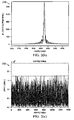
- FIG. 2(a) illustrates a diagram 210 of a time domain plot of an unclipped signal, as may be generated by the signal generator 110. Notably, the unclipped signal has peaks (i.e., portions of the signal exceeding the magnitude threshold), which are circled in the diagram 210.
- FIG. 1 illustrates a noise clipping circuit 100 comprising a signal generator 110, a CFR module 120, a radio module 125, a power amplifier 130, and a transmit antenna 140.
- the signal generator 110 is configured to generate a digital signal, which is processed by the
- FIG. 2(b) illustrates a diagram 220 of a clipping noise signal, as may be generated by the CFR module 120.
- the noise signal depicted in the diagram 220 is introduced into the unclipped signal depicted in the diagram 210 to clip or otherwise eliminate many or all of the signal peaks.
- FIG. 2(c) illustrates a diagram 230 of a clipped signal.. As shown, most of the peaks in the unclipped signal have been removed from the clipped signal.
- FIG. 2(d) illustrates a chart 240 of a complementary cumulative distribution function (CCDF) of the clipped and unclipped signals. As shown, the clipped signal has a far lower probability of exceeding the magnitude threshold than the unclipped signal, and consequently will allow the power amplifier 130 to operate more efficiently and/or in a more linear fashion.
- CCDF complementary cumulative distribution function
- FIG. 3 illustrates a network 300 for communicating data.
- the network 300 comprises an access point (AP) 310 having a coverage area 312, a plurality of user equipments (UEs) 320, and a backhaul network 330.
- the AP 310 may comprise any component capable of providing wireless access by, inter alia, establishing uplink (dashed line) and/or downlink (dotted line) connections with the UEs 320, such as a base station, an enhanced base station (eNB), a femtocell, and other wirelessly enabled devices.
- the UEs 320 may comprise any component capable of establishing a wireless connection with the AP 310, such as "smartphone", mobile terminal, PC, tablet, netbook and the like.
- the backhaul network 330 may be any component or collection of components that allow data to be exchanged between the AP 310 and a remote end (not shown).
- the network 300 may comprise various other wireless devices, such as relays, femtocells, etc.
- FIG. 4 illustrates a conventional multi-carrier multi-channel transmitter 400 that includes a first carrier (Carrier-1) and a second carrier (Carrier-2). As shown, both carriers are split into four transmit paths (TRx paths), after which a first set of beamforming weight vectors (W 1 , W 2 , W 3 , W 4 ) are applied to the paths of the Carrier-1 and a second set of beamforming weight vectors (W 1 ', W 2 ', W 3 ', W 4 ') are applied to the paths of the Carrier-2.
- TRx paths transmit paths
- the combined signals traveling over each of the TRx paths are clipped by the CFR modules (CFR 1 , CFR 2 , CFR 3 , CFR 4 ) before being transmitted over the antennas by the transmitter modules (TRx 1 , TRx 2 , TRx 3 , TRx 4 ).
- FIG. 5 illustrates a network 500 in which a cell tower 510 is transmitting a signal to a mobile station 520.
- the cell tower 510 has a maximum Effective Isotropically Radiated Power (EIRP) trajectory as represented by the dashed arrowhead extending horizontally from the cell tower's 510 antenna. Accordingly, the cell tower 510 may electronically tilt its antenna downward by a tilt angle ( ⁇ ) in order to achieve a higher SNR at the mobile station 520.
- FIG. 6 shows an antenna pattern graphed with Cartesian coordinates 610 and polar coordinates 620. As shown, some spatial positions (e.g., 240 degrees) show higher gain than others, which allows for better signal reception quality at those respective locations.
- the crest factor reduction includes introducing a clipping noise signal that has the same relative amplitude-phase relationship as the data signal.
- the amplitude-phase relationship of a signal may refer to a ratio between the signal's amplitude component and phase component at a given instance in time.
- the phases/amplitudes discussed herein are measured at the antenna point, and represent relative values which are computed in accordance with a distributed beamforming (DBF) application/function to steer a beam in a desired direction.
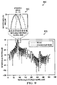
- FIG. 7 illustrates an antenna pattern 710 for a signal and clipped signal as might result from a conventional CFR technique, as is demonstrated in the diagram 720.
- crest factor is achieved by introducing a clipping noise vector 722 into an unclipped signal 721 to reduce the magnitude of the resulting clipped signal to within a CFR threshold (indicated by the dashed circle in the diagram 720).
- the amplitude-phase relationships of the clipping noise vector 722 and the unclipped signal 721 are identical, with the clipping noise vector being 180 degrees out of phase with the unclipped signal 721.
- the clipping noise and the data signal have a similar antenna pattern, with the clipped signal having a lower gain than the data signal.
- the clipping noise signal and the data signal both peak at around 90 degrees, with a difference ( ⁇ 1 ) of about 30 decibels (dBs).
- FIG. 8 illustrates an antenna pattern 810 for a signal and clipped signal as might result from an embodiment CFR techniques performed in accordance with aspects of this disclosure, as is demonstrated in the diagram 820. More specifically, embodiments of this disclosure achieve crest factor reduction by introducing into the unclipped signal 821 a clipping noise vector 822 having a different amplitude-phase relationship than the unclipped signal 821. As a result, the relative phasing of the resulting clipped signal 823 differs from that of the unclipped signal 821. The advantages are two-fold.
- a larger magnitude clipping noise vector 821 may be used, thereby allowing for the power amplifier to operate in a more efficient (e.g., linear) operating region.
- the antenna pattern of the clipping noise signal can be steered in a different direction than the data signal, thereby allowing for increased spatial selectivity. For instance, the clipped signal could be steered away from potential user locations, thereby increasing SNRs of those users. This is exemplified by the antenna pattern 810, which shows a difference ( ⁇ 2 ) of about 45 decibels (dBs) at the 90 degrees (where the signal peaks), which is about 15 dBs greater than the ⁇ 1 obtained through conventional CFR.
- FIG. 9 illustrates a graph 910 of normalized antenna patterns, where the amplitudes of the data signal and the steered clip noise signal have been normalized to better show the difference (or steering angle) between the signal and steered clip signal. As shown, a steering angle of approximately 5 degrees is attainable.
- FIG. 10 illustrates a flowchart of a method 1000 for performing crest factor reduction in accordance with aspects of this disclosure, as might be performed by a transmitter.
- the method 1000 begins at step 1010, where the transmitter receives a data signal that is determined by a CFR module of the transmitter to have an initial magnitude that exceeds a CFR threshold.
- the method 1000 proceeds to step 1020, where the transmitter determines a desired steering angle for the signal transmission.
- the transmitter may determine the desired steering angle in accordance with a distribution of users throughout a cell or coverage area. For instance, the steering angle may be selected such that the clipping noise signal's antenna pattern has relatively low gain in spatial locations having a high density of users.
- the method 1000 proceeds to step 1030, where the transmitter selects amplitude and phase parameters of the clipping noise signal in accordance with the desired steering angle.
- the amplitude and phase parameters of the clipping noise signal may be selected such that the amplitude-phase relationship of the clipping noise signal is different than an amplitude-phase relationship of the unclipped signal.
- the degree to which the amplitude-phase relationships differ may be a function of the steering angle determined in step 1020.
- the method 1000 proceeds to step 1040, where the transmitter introduces the clipping noise signal into the data signal to obtain a clipped data signal.
- the method 1000 proceeds to step 1050, where the transmitter amplifies the clipped data signal.
- the method 1000 proceeds to step 1060, where the transmitter transmits the amplified data signal.
- FIG. 11 illustrates a block diagram of an embodiment of a communications device 1100.
- the communications device 1100 may include a processor 1104, a memory 1106, and a plurality of wireless interfaces 1110.
- the processor 1104 may be any component capable of performing computations and/or other processing related tasks
- the memory 1106 may be any component capable of storing programming and/or instructions for the processor 1104.
- the interface 1110 may be any component or collection of components that allows the communications device 1100 to communicate wirelessly.
Landscapes
- Engineering & Computer Science (AREA)
- Computer Networks & Wireless Communication (AREA)
- Signal Processing (AREA)
- Radio Transmission System (AREA)
- Noise Elimination (AREA)
- Transmitters (AREA)
Applications Claiming Priority (2)
| Application Number | Priority Date | Filing Date | Title |
|---|---|---|---|
| US13/797,408 US8995570B2 (en) | 2013-03-12 | 2013-03-12 | Methods and systems for beam steering crest factor reduction (CFR) clip noise |
| PCT/CN2014/073263 WO2014139417A1 (en) | 2013-03-12 | 2014-03-12 | Methods and systems for beam steering crest factor reduction (cfr) clip noise |
Publications (3)
| Publication Number | Publication Date |
|---|---|
| EP2962437A1 EP2962437A1 (en) | 2016-01-06 |
| EP2962437A4 EP2962437A4 (en) | 2016-03-02 |
| EP2962437B1 true EP2962437B1 (en) | 2019-10-16 |
Family
ID=51527001
Family Applications (1)
| Application Number | Title | Priority Date | Filing Date |
|---|---|---|---|
| EP14764905.7A Active EP2962437B1 (en) | 2013-03-12 | 2014-03-12 | Methods and systems for beam steering crest factor reduction (cfr) clip noise |
Country Status (5)
| Country | Link |
|---|---|
| US (1) | US8995570B2 (zh) |
| EP (1) | EP2962437B1 (zh) |
| CN (1) | CN105009536B (zh) |
| ES (1) | ES2765275T3 (zh) |
| WO (1) | WO2014139417A1 (zh) |
Families Citing this family (6)
| Publication number | Priority date | Publication date | Assignee | Title |
|---|---|---|---|---|
| US9509541B1 (en) * | 2015-08-10 | 2016-11-29 | Altiostar Networks, Inc. | Crest factor reduction |
| CN107094038B (zh) * | 2017-03-06 | 2020-07-24 | 上海华为技术有限公司 | 一种天线系统功率调整的方法、装置及系统 |
| CN112166585B (zh) * | 2018-06-01 | 2024-02-23 | 瑞典爱立信有限公司 | 超宽带峰值因子降低 |
| US10594269B2 (en) * | 2018-08-08 | 2020-03-17 | Shenzhen GOODIX Technology Co., Ltd. | Crest factor reduction in power amplifier circuits |
| WO2022207088A1 (en) * | 2021-03-31 | 2022-10-06 | Telefonaktiebolaget Lm Ericsson (Publ) | Controlling peak-to-average power ratio reduction |
| FR3137235A1 (fr) * | 2022-06-27 | 2023-12-29 | Commissariat A L'energie Atomique Et Aux Energies Alternatives | Procédé de réduction du facteur de crête d’un signal de type OFDM, produits programme d’ordinateur et dispositifs correspondants. |
Citations (1)
| Publication number | Priority date | Publication date | Assignee | Title |
|---|---|---|---|---|
| WO2006062291A2 (en) * | 2004-12-11 | 2006-06-15 | Electronics And Telecommunications Research Institute | A digital clipping method for a transmitter of an orthogonal frequency division multiple access system |
Family Cites Families (6)
| Publication number | Priority date | Publication date | Assignee | Title |
|---|---|---|---|---|
| CN101388864A (zh) * | 2007-09-11 | 2009-03-18 | 上海睿智通无线技术有限公司 | 一种正交频分复用通信系统信道估计方法与装置 |
| CN101867541B (zh) | 2009-04-20 | 2013-02-13 | 大唐移动通信设备有限公司 | 一种信号波峰削除的方法及设备 |
| JP5212402B2 (ja) | 2010-02-24 | 2013-06-19 | 住友電気工業株式会社 | ピーク電力抑制回路とこの回路を有する通信装置 |
| CN101938448B (zh) * | 2010-08-30 | 2013-11-06 | 京信通信系统(中国)有限公司 | 具有自动载波跟踪功能的cfr处理方法及装置、通信系统 |
| CN102611656A (zh) * | 2012-03-21 | 2012-07-25 | 武汉邮电科学研究院 | 增强的适合lte系统上行的信道估计方法及装置 |
| CN104854791B (zh) * | 2012-10-01 | 2017-09-22 | 瑞典爱立信有限公司 | Aas传送器失真改进 |
-
2013
- 2013-03-12 US US13/797,408 patent/US8995570B2/en active Active
-
2014
- 2014-03-12 WO PCT/CN2014/073263 patent/WO2014139417A1/en active Application Filing
- 2014-03-12 CN CN201480014476.9A patent/CN105009536B/zh active Active
- 2014-03-12 EP EP14764905.7A patent/EP2962437B1/en active Active
- 2014-03-12 ES ES14764905T patent/ES2765275T3/es active Active
Patent Citations (1)
| Publication number | Priority date | Publication date | Assignee | Title |
|---|---|---|---|---|
| WO2006062291A2 (en) * | 2004-12-11 | 2006-06-15 | Electronics And Telecommunications Research Institute | A digital clipping method for a transmitter of an orthogonal frequency division multiple access system |
Also Published As
| Publication number | Publication date |
|---|---|
| US8995570B2 (en) | 2015-03-31 |
| ES2765275T3 (es) | 2020-06-08 |
| WO2014139417A1 (en) | 2014-09-18 |
| CN105009536B (zh) | 2018-09-28 |
| EP2962437A1 (en) | 2016-01-06 |
| US20140270016A1 (en) | 2014-09-18 |
| CN105009536A (zh) | 2015-10-28 |
| EP2962437A4 (en) | 2016-03-02 |
Similar Documents
| Publication | Publication Date | Title |
|---|---|---|
| EP2962437B1 (en) | Methods and systems for beam steering crest factor reduction (cfr) clip noise | |
| US9819526B2 (en) | Apparatus and methods for low PAPR transmission in MIMO systems | |
| WO2017193953A1 (en) | Methods and apparatus for generating beam pattern with wider beam width in phased antenna array | |
| US10205491B2 (en) | System and method for large scale multiple input multiple output communications | |
| Obara et al. | Joint processing of analog fixed beamforming and CSI-based precoding for super high bit rate massive MIMO transmission using higher frequency bands | |
| US9065605B2 (en) | Methods and systems for crest factor reduction in multi-carrier multi-channel architectures | |
| US9219505B2 (en) | AAS transmitter distortion improvement | |
| US11277103B2 (en) | Digital predistortion device and method | |
| US10511359B2 (en) | Transmission method with double directivity | |
| JP6128083B2 (ja) | 無線通信装置及び算出方法 | |
| CN107017925B (zh) | 一种有源阵列天线的信号处理方法和装置 | |
| EP3465952B1 (en) | Method and apparatus for antenna array calibration using on-board receiver | |
| US20230081201A1 (en) | Passive Intermodulation Aware Beamforming | |
| US20110223872A1 (en) | Wireless transceiving apparatus | |
| US11616539B2 (en) | Beamforming method and apparatus for massive MIMO system | |
| KR102375697B1 (ko) | 빔 공간 mimo에서 기저대역 신호 변조 방법 및 장치 | |
| KR20160082882A (ko) | 하이브리드 상향링크 빔포밍 기술 | |
| US20230216574A1 (en) | Systems and methods for massive multiple-input multiple-output antenna calibration | |
| CN108233959B (zh) | 一种消除数字相控阵子阵间干扰的方法 | |
| JP4095462B2 (ja) | 無線装置および無線基地局 | |
| Rodrigues et al. | Improved Magnitude Weighting Technique for Wireless Sensor Network Beamformer | |
| JP6476770B2 (ja) | 基地局装置 | |
| Ng | Digital Predistortion of Millimeter-Wave Phased Antenna Arrays | |
| CN116055275A (zh) | 基于波束方向图动态匹配的低轨卫星papr降低方法及装置 | |
| Tragas | Over-the-Air Proof of Concepts |
Legal Events
| Date | Code | Title | Description |
|---|---|---|---|
| PUAI | Public reference made under article 153(3) epc to a published international application that has entered the european phase |
Free format text: ORIGINAL CODE: 0009012 |
|
| 17P | Request for examination filed |
Effective date: 20150929 |
|
| AK | Designated contracting states |
Kind code of ref document: A1 Designated state(s): AL AT BE BG CH CY CZ DE DK EE ES FI FR GB GR HR HU IE IS IT LI LT LU LV MC MK MT NL NO PL PT RO RS SE SI SK SM TR |
|
| AX | Request for extension of the european patent |
Extension state: BA ME |
|
| A4 | Supplementary search report drawn up and despatched |
Effective date: 20160202 |
|
| RIC1 | Information provided on ipc code assigned before grant |
Ipc: H04B 7/04 20060101ALN20160127BHEP Ipc: H04L 27/26 20060101AFI20160127BHEP |
|
| DAX | Request for extension of the european patent (deleted) | ||
| STAA | Information on the status of an ep patent application or granted ep patent |
Free format text: STATUS: EXAMINATION IS IN PROGRESS |
|
| 17Q | First examination report despatched |
Effective date: 20180621 |
|
| REG | Reference to a national code |
Ref country code: DE Ref legal event code: R079 Ref document number: 602014055281 Country of ref document: DE Free format text: PREVIOUS MAIN CLASS: H04L0027000000 Ipc: H04L0027260000 |
|
| GRAP | Despatch of communication of intention to grant a patent |
Free format text: ORIGINAL CODE: EPIDOSNIGR1 |
|
| STAA | Information on the status of an ep patent application or granted ep patent |
Free format text: STATUS: GRANT OF PATENT IS INTENDED |
|
| RIC1 | Information provided on ipc code assigned before grant |
Ipc: H04B 7/04 20170101ALN20190418BHEP Ipc: H04L 27/26 20060101AFI20190418BHEP |
|
| INTG | Intention to grant announced |
Effective date: 20190514 |
|
| GRAS | Grant fee paid |
Free format text: ORIGINAL CODE: EPIDOSNIGR3 |
|
| GRAA | (expected) grant |
Free format text: ORIGINAL CODE: 0009210 |
|
| STAA | Information on the status of an ep patent application or granted ep patent |
Free format text: STATUS: THE PATENT HAS BEEN GRANTED |
|
| AK | Designated contracting states |
Kind code of ref document: B1 Designated state(s): AL AT BE BG CH CY CZ DE DK EE ES FI FR GB GR HR HU IE IS IT LI LT LU LV MC MK MT NL NO PL PT RO RS SE SI SK SM TR |
|
| REG | Reference to a national code |
Ref country code: GB Ref legal event code: FG4D |
|
| REG | Reference to a national code |
Ref country code: DE Ref legal event code: R096 Ref document number: 602014055281 Country of ref document: DE Ref country code: CH Ref legal event code: EP |
|
| REG | Reference to a national code |
Ref country code: IE Ref legal event code: FG4D |
|
| REG | Reference to a national code |
Ref country code: AT Ref legal event code: REF Ref document number: 1192390 Country of ref document: AT Kind code of ref document: T Effective date: 20191115 |
|
| REG | Reference to a national code |
Ref country code: NL Ref legal event code: MP Effective date: 20191016 |
|
| REG | Reference to a national code |
Ref country code: LT Ref legal event code: MG4D |
|
| REG | Reference to a national code |
Ref country code: AT Ref legal event code: MK05 Ref document number: 1192390 Country of ref document: AT Kind code of ref document: T Effective date: 20191016 |
|
| PG25 | Lapsed in a contracting state [announced via postgrant information from national office to epo] |
Ref country code: GR Free format text: LAPSE BECAUSE OF FAILURE TO SUBMIT A TRANSLATION OF THE DESCRIPTION OR TO PAY THE FEE WITHIN THE PRESCRIBED TIME-LIMIT Effective date: 20200117 Ref country code: PL Free format text: LAPSE BECAUSE OF FAILURE TO SUBMIT A TRANSLATION OF THE DESCRIPTION OR TO PAY THE FEE WITHIN THE PRESCRIBED TIME-LIMIT Effective date: 20191016 Ref country code: NO Free format text: LAPSE BECAUSE OF FAILURE TO SUBMIT A TRANSLATION OF THE DESCRIPTION OR TO PAY THE FEE WITHIN THE PRESCRIBED TIME-LIMIT Effective date: 20200116 Ref country code: NL Free format text: LAPSE BECAUSE OF FAILURE TO SUBMIT A TRANSLATION OF THE DESCRIPTION OR TO PAY THE FEE WITHIN THE PRESCRIBED TIME-LIMIT Effective date: 20191016 Ref country code: LT Free format text: LAPSE BECAUSE OF FAILURE TO SUBMIT A TRANSLATION OF THE DESCRIPTION OR TO PAY THE FEE WITHIN THE PRESCRIBED TIME-LIMIT Effective date: 20191016 Ref country code: AT Free format text: LAPSE BECAUSE OF FAILURE TO SUBMIT A TRANSLATION OF THE DESCRIPTION OR TO PAY THE FEE WITHIN THE PRESCRIBED TIME-LIMIT Effective date: 20191016 Ref country code: SE Free format text: LAPSE BECAUSE OF FAILURE TO SUBMIT A TRANSLATION OF THE DESCRIPTION OR TO PAY THE FEE WITHIN THE PRESCRIBED TIME-LIMIT Effective date: 20191016 Ref country code: LV Free format text: LAPSE BECAUSE OF FAILURE TO SUBMIT A TRANSLATION OF THE DESCRIPTION OR TO PAY THE FEE WITHIN THE PRESCRIBED TIME-LIMIT Effective date: 20191016 Ref country code: PT Free format text: LAPSE BECAUSE OF FAILURE TO SUBMIT A TRANSLATION OF THE DESCRIPTION OR TO PAY THE FEE WITHIN THE PRESCRIBED TIME-LIMIT Effective date: 20200217 Ref country code: FI Free format text: LAPSE BECAUSE OF FAILURE TO SUBMIT A TRANSLATION OF THE DESCRIPTION OR TO PAY THE FEE WITHIN THE PRESCRIBED TIME-LIMIT Effective date: 20191016 Ref country code: BG Free format text: LAPSE BECAUSE OF FAILURE TO SUBMIT A TRANSLATION OF THE DESCRIPTION OR TO PAY THE FEE WITHIN THE PRESCRIBED TIME-LIMIT Effective date: 20200116 |
|
| PG25 | Lapsed in a contracting state [announced via postgrant information from national office to epo] |
Ref country code: IS Free format text: LAPSE BECAUSE OF FAILURE TO SUBMIT A TRANSLATION OF THE DESCRIPTION OR TO PAY THE FEE WITHIN THE PRESCRIBED TIME-LIMIT Effective date: 20200224 Ref country code: RS Free format text: LAPSE BECAUSE OF FAILURE TO SUBMIT A TRANSLATION OF THE DESCRIPTION OR TO PAY THE FEE WITHIN THE PRESCRIBED TIME-LIMIT Effective date: 20191016 Ref country code: HR Free format text: LAPSE BECAUSE OF FAILURE TO SUBMIT A TRANSLATION OF THE DESCRIPTION OR TO PAY THE FEE WITHIN THE PRESCRIBED TIME-LIMIT Effective date: 20191016 |
|
| REG | Reference to a national code |
Ref country code: ES Ref legal event code: FG2A Ref document number: 2765275 Country of ref document: ES Kind code of ref document: T3 Effective date: 20200608 |
|
| PG25 | Lapsed in a contracting state [announced via postgrant information from national office to epo] |
Ref country code: AL Free format text: LAPSE BECAUSE OF FAILURE TO SUBMIT A TRANSLATION OF THE DESCRIPTION OR TO PAY THE FEE WITHIN THE PRESCRIBED TIME-LIMIT Effective date: 20191016 |
|
| REG | Reference to a national code |
Ref country code: DE Ref legal event code: R097 Ref document number: 602014055281 Country of ref document: DE |
|
| PG2D | Information on lapse in contracting state deleted |
Ref country code: IS |
|
| PG25 | Lapsed in a contracting state [announced via postgrant information from national office to epo] |
Ref country code: DK Free format text: LAPSE BECAUSE OF FAILURE TO SUBMIT A TRANSLATION OF THE DESCRIPTION OR TO PAY THE FEE WITHIN THE PRESCRIBED TIME-LIMIT Effective date: 20191016 Ref country code: EE Free format text: LAPSE BECAUSE OF FAILURE TO SUBMIT A TRANSLATION OF THE DESCRIPTION OR TO PAY THE FEE WITHIN THE PRESCRIBED TIME-LIMIT Effective date: 20191016 Ref country code: CZ Free format text: LAPSE BECAUSE OF FAILURE TO SUBMIT A TRANSLATION OF THE DESCRIPTION OR TO PAY THE FEE WITHIN THE PRESCRIBED TIME-LIMIT Effective date: 20191016 Ref country code: RO Free format text: LAPSE BECAUSE OF FAILURE TO SUBMIT A TRANSLATION OF THE DESCRIPTION OR TO PAY THE FEE WITHIN THE PRESCRIBED TIME-LIMIT Effective date: 20191016 Ref country code: IS Free format text: LAPSE BECAUSE OF FAILURE TO SUBMIT A TRANSLATION OF THE DESCRIPTION OR TO PAY THE FEE WITHIN THE PRESCRIBED TIME-LIMIT Effective date: 20200216 |
|
| PGFP | Annual fee paid to national office [announced via postgrant information from national office to epo] |
Ref country code: ES Payment date: 20200401 Year of fee payment: 7 |
|
| PLBE | No opposition filed within time limit |
Free format text: ORIGINAL CODE: 0009261 |
|
| STAA | Information on the status of an ep patent application or granted ep patent |
Free format text: STATUS: NO OPPOSITION FILED WITHIN TIME LIMIT |
|
| PG25 | Lapsed in a contracting state [announced via postgrant information from national office to epo] |
Ref country code: SK Free format text: LAPSE BECAUSE OF FAILURE TO SUBMIT A TRANSLATION OF THE DESCRIPTION OR TO PAY THE FEE WITHIN THE PRESCRIBED TIME-LIMIT Effective date: 20191016 Ref country code: SM Free format text: LAPSE BECAUSE OF FAILURE TO SUBMIT A TRANSLATION OF THE DESCRIPTION OR TO PAY THE FEE WITHIN THE PRESCRIBED TIME-LIMIT Effective date: 20191016 |
|
| 26N | No opposition filed |
Effective date: 20200717 |
|
| PG25 | Lapsed in a contracting state [announced via postgrant information from national office to epo] |
Ref country code: MC Free format text: LAPSE BECAUSE OF FAILURE TO SUBMIT A TRANSLATION OF THE DESCRIPTION OR TO PAY THE FEE WITHIN THE PRESCRIBED TIME-LIMIT Effective date: 20191016 |
|
| REG | Reference to a national code |
Ref country code: CH Ref legal event code: PL |
|
| PG25 | Lapsed in a contracting state [announced via postgrant information from national office to epo] |
Ref country code: SI Free format text: LAPSE BECAUSE OF FAILURE TO SUBMIT A TRANSLATION OF THE DESCRIPTION OR TO PAY THE FEE WITHIN THE PRESCRIBED TIME-LIMIT Effective date: 20191016 |
|
| REG | Reference to a national code |
Ref country code: BE Ref legal event code: MM Effective date: 20200331 |
|
| PG25 | Lapsed in a contracting state [announced via postgrant information from national office to epo] |
Ref country code: LU Free format text: LAPSE BECAUSE OF NON-PAYMENT OF DUE FEES Effective date: 20200312 |
|
| PG25 | Lapsed in a contracting state [announced via postgrant information from national office to epo] |
Ref country code: FR Free format text: LAPSE BECAUSE OF NON-PAYMENT OF DUE FEES Effective date: 20200331 Ref country code: IE Free format text: LAPSE BECAUSE OF NON-PAYMENT OF DUE FEES Effective date: 20200312 Ref country code: CH Free format text: LAPSE BECAUSE OF NON-PAYMENT OF DUE FEES Effective date: 20200331 Ref country code: LI Free format text: LAPSE BECAUSE OF NON-PAYMENT OF DUE FEES Effective date: 20200331 |
|
| PG25 | Lapsed in a contracting state [announced via postgrant information from national office to epo] |
Ref country code: BE Free format text: LAPSE BECAUSE OF NON-PAYMENT OF DUE FEES Effective date: 20200331 |
|
| GBPC | Gb: european patent ceased through non-payment of renewal fee |
Effective date: 20200312 |
|
| PG25 | Lapsed in a contracting state [announced via postgrant information from national office to epo] |
Ref country code: GB Free format text: LAPSE BECAUSE OF NON-PAYMENT OF DUE FEES Effective date: 20200312 |
|
| REG | Reference to a national code |
Ref country code: ES Ref legal event code: FD2A Effective date: 20220523 |
|
| PG25 | Lapsed in a contracting state [announced via postgrant information from national office to epo] |
Ref country code: TR Free format text: LAPSE BECAUSE OF FAILURE TO SUBMIT A TRANSLATION OF THE DESCRIPTION OR TO PAY THE FEE WITHIN THE PRESCRIBED TIME-LIMIT Effective date: 20191016 Ref country code: MT Free format text: LAPSE BECAUSE OF FAILURE TO SUBMIT A TRANSLATION OF THE DESCRIPTION OR TO PAY THE FEE WITHIN THE PRESCRIBED TIME-LIMIT Effective date: 20191016 Ref country code: CY Free format text: LAPSE BECAUSE OF FAILURE TO SUBMIT A TRANSLATION OF THE DESCRIPTION OR TO PAY THE FEE WITHIN THE PRESCRIBED TIME-LIMIT Effective date: 20191016 |
|
| PG25 | Lapsed in a contracting state [announced via postgrant information from national office to epo] |
Ref country code: MK Free format text: LAPSE BECAUSE OF FAILURE TO SUBMIT A TRANSLATION OF THE DESCRIPTION OR TO PAY THE FEE WITHIN THE PRESCRIBED TIME-LIMIT Effective date: 20191016 |
|
| PG25 | Lapsed in a contracting state [announced via postgrant information from national office to epo] |
Ref country code: ES Free format text: LAPSE BECAUSE OF NON-PAYMENT OF DUE FEES Effective date: 20210313 |
|
| PGFP | Annual fee paid to national office [announced via postgrant information from national office to epo] |
Ref country code: IT Payment date: 20230213 Year of fee payment: 10 |
|
| P01 | Opt-out of the competence of the unified patent court (upc) registered |
Effective date: 20230524 |
|
| PGFP | Annual fee paid to national office [announced via postgrant information from national office to epo] |
Ref country code: DE Payment date: 20240130 Year of fee payment: 11 |