EP2961679B1 - Bremsregelsystem für aufzug - Google Patents
Bremsregelsystem für aufzug Download PDFInfo
- Publication number
- EP2961679B1 EP2961679B1 EP14711000.1A EP14711000A EP2961679B1 EP 2961679 B1 EP2961679 B1 EP 2961679B1 EP 14711000 A EP14711000 A EP 14711000A EP 2961679 B1 EP2961679 B1 EP 2961679B1
- Authority
- EP
- European Patent Office
- Prior art keywords
- brakes
- motor
- electronic circuit
- emergency
- power supply
- Prior art date
- Legal status (The legal status is an assumption and is not a legal conclusion. Google has not performed a legal analysis and makes no representation as to the accuracy of the status listed.)
- Not-in-force
Links
- 230000009471 action Effects 0.000 claims description 8
- 230000001939 inductive effect Effects 0.000 claims description 6
- 238000012544 monitoring process Methods 0.000 claims description 5
- 230000002401 inhibitory effect Effects 0.000 claims description 2
- 230000001960 triggered effect Effects 0.000 claims description 2
- 230000004913 activation Effects 0.000 claims 2
- 235000021183 entrée Nutrition 0.000 description 8
- 238000001514 detection method Methods 0.000 description 4
- 230000008901 benefit Effects 0.000 description 2
- 239000004065 semiconductor Substances 0.000 description 2
- 230000007704 transition Effects 0.000 description 2
- 238000006677 Appel reaction Methods 0.000 description 1
- 241001415961 Gaviidae Species 0.000 description 1
- 230000008859 change Effects 0.000 description 1
- 229940082150 encore Drugs 0.000 description 1
- 238000009434 installation Methods 0.000 description 1
- 230000010354 integration Effects 0.000 description 1
- 230000007257 malfunction Effects 0.000 description 1
- 230000010287 polarization Effects 0.000 description 1
- 238000012797 qualification Methods 0.000 description 1
- 230000009467 reduction Effects 0.000 description 1
- 230000001360 synchronised effect Effects 0.000 description 1
Images
Classifications
-
- B—PERFORMING OPERATIONS; TRANSPORTING
- B66—HOISTING; LIFTING; HAULING
- B66B—ELEVATORS; ESCALATORS OR MOVING WALKWAYS
- B66B1/00—Control systems of elevators in general
- B66B1/24—Control systems with regulation, i.e. with retroactive action, for influencing travelling speed, acceleration, or deceleration
- B66B1/28—Control systems with regulation, i.e. with retroactive action, for influencing travelling speed, acceleration, or deceleration electrical
- B66B1/32—Control systems with regulation, i.e. with retroactive action, for influencing travelling speed, acceleration, or deceleration electrical effective on braking devices, e.g. acting on electrically controlled brakes
-
- B—PERFORMING OPERATIONS; TRANSPORTING
- B66—HOISTING; LIFTING; HAULING
- B66B—ELEVATORS; ESCALATORS OR MOVING WALKWAYS
- B66B5/00—Applications of checking, fault-correcting, or safety devices in elevators
- B66B5/0006—Monitoring devices or performance analysers
- B66B5/0037—Performance analysers
-
- B—PERFORMING OPERATIONS; TRANSPORTING
- B66—HOISTING; LIFTING; HAULING
- B66B—ELEVATORS; ESCALATORS OR MOVING WALKWAYS
- B66B5/00—Applications of checking, fault-correcting, or safety devices in elevators
- B66B5/02—Applications of checking, fault-correcting, or safety devices in elevators responsive to abnormal operating conditions
- B66B5/027—Applications of checking, fault-correcting, or safety devices in elevators responsive to abnormal operating conditions to permit passengers to leave an elevator car in case of failure, e.g. moving the car to a reference floor or unlocking the door
-
- B—PERFORMING OPERATIONS; TRANSPORTING
- B66—HOISTING; LIFTING; HAULING
- B66B—ELEVATORS; ESCALATORS OR MOVING WALKWAYS
- B66B5/00—Applications of checking, fault-correcting, or safety devices in elevators
- B66B5/0087—Devices facilitating maintenance, repair or inspection tasks
-
- B—PERFORMING OPERATIONS; TRANSPORTING
- B66—HOISTING; LIFTING; HAULING
- B66B—ELEVATORS; ESCALATORS OR MOVING WALKWAYS
- B66B5/00—Applications of checking, fault-correcting, or safety devices in elevators
- B66B5/0087—Devices facilitating maintenance, repair or inspection tasks
- B66B5/0093—Testing of safety devices
Definitions
- the present invention relates to a brake control system for an elevator.
- the current elevators include a motor equipped with power-down brakes which, in normal operating mode, are energized when the car is moving.
- US 2011 / 048863A1 describes a device for controlling two braking members of an elevator, adapted to generate, according to a wiring logic by connectors, actuating signals allowing at least two modes of operation including a normal mode where two actuation signals are provided synchronously to the coils of the braking members, and a test mode of one of the two braking members where an actuating signal is supplied to the coil of the braking member under test, and another signal of actuation to permanently release the second braking member is supplied to the coil of the latter.
- the brake control system combines all the functions necessary for controlling the brakes. Complex wiring outside the system is avoided.
- the system can be qualified and approved to ensure that all functions are met with maximum reliability.
- the operation in emergency mode can be guaranteed, if desired, in a large number of situations such as the absence of current, a failure of the maneuver, a failure of the motor encoder or a failure of the converter supplying the motor, .. some of these situations are not currently covered by some cabling.
- the emergency function operated in emergency mode by the control system according to the invention preferably does not involve engine braking torque by short circuit motor phases. This guarantees a much more efficient backup when the cab is near equilibrium.
- the electronic circuit is preferably arranged such that in case of simultaneous action by an operator on the test inputs of the brakes, they are not powered.
- the electronic circuit advantageously comprises a single printed circuit board.
- the braking power supply is advantageously the 110 V or 230 V single-phase network, possibly via an inverter.
- the electronic circuit is preferably arranged to measure, in emergency mode, the speed of the motor from the voltage at its terminals, and to interrupt the supply of the brakes if a threshold voltage representative of a speed is exceeded. excessive.
- the motor comprises an inductive sensor connected to the electronic circuit and to inform it on the speed of the motor. If excessive speed is detected, brake power is interrupted.
- the intermittent release of the brakes in emergency mode preferably comprises phases of supply of the brakes for a period of between 2 and 8 seconds.
- the intermittent release of the brakes in emergency mode also preferably includes non-supply phases of the brakes for a period of between 2 and 8 seconds.
- the brakes are preferably powered, in normal operating mode, via power terminals connected electrically in series and internally with an emergency cut-off. Thus, this emergency shutdown can interrupt the supply of brakes in case of emergency.
- the brakes are preferably powered, in parallel emergency mode, forcing the closure of this emergency cut.
- the advantage of an internal break in replacement of an external contactor is to reduce the noise generated by the change of state of the contactor, by modifying the location where the contactor is usually located.
- the system may include an arrival detection input on the cabin floor, which changes state upon arrival from the cabin to the floor; operation in mode emergency can be modified to interrupt the opening of the brakes when said arrival arrival detection input is in a state that corresponds to the arrival of the cabin to the floor.
- the system comprises a diode voltage, resistance and varistor voltage clipping circuit, in parallel with each supply output of a brake.
- the electronic circuit according to the invention comprises a microprocessor / microcontroller self-monitoring unit which monitors the coherence of the states of the different inputs and outputs and activates an electromagnetic relay when the operation of the electronic circuit is considered as non-faulty.
- the output of this relay can be used in a safety chain of the elevator.
- the invention also relates to an elevator equipped with a control system according to the invention.
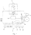
- This system 1 comprises an electronic circuit board, preferably single, supporting a number of components arranged to perform the desired functions.
- the electronic circuit may comprise a microcontroller 20 and the appropriate interfaces and power relays.
- the electronic circuit includes terminals that allow its electrical connection to the various elements controlled by the system or controlling the operation of the brakes.
- a power supply 2 for example 230V 50Hz single phase, which corresponds to the network or an inverter, is connected to the circuit.
- Brakes 4 and 5 are connected to terminal pairs "Brake1" and “Brake2" respectively of the circuit.
- the brakes 4 and 5 are out of power, that is to say that in the unpowered state, they block the rotation of the motor shaft.
- Input 10 is connected to a dimmer that powers the motor or to a controller of elevator operation.
- the output voltage of the drive is present on the motor control terminals 25 to 27 of the electronic circuit.
- the brake to be kept open is selected by means of two respective logic inputs T 1 and T 2 , each connected, for example, to a pushbutton or other switch.
- the brake which remains in normal operation is controlled by the logic input 10 and the energy is taken from the power supply 2.
- the electronic circuit is arranged such that if the inputs T 1 and T 2 are closed simultaneously, the brakes are not powered.
- the transition to emergency mode is validated using a logic input 12 (also called “enable”), connected to a key switch or a chain rescue, for example.
- a logic input 12 also called “enable”
- the control inputs 10 also called “open”
- test T 1 and T 2 are then inhibited and both brakes 4 and 5 are controlled simultaneously, the energy of supply of the brakes being taken from the power supply 2.
- the brakes are controlled in emergency mode by a logic input 14, connected to a push button or a controller of the operation of the elevator.
- the synchronous motor M When the brakes are open, because of the state imposed on the input 14, the synchronous motor M is likely to be driven by the load of the cabin. We measure its speed using the voltage induced at its terminals, connected to the inputs 25 to 27 of the electronic circuit. When the voltage between phases reaches a threshold voltage, for example 280V peak, the system 1 cuts the current in the brakes 4 and 5, in order to stop the rotation of the motor.
- a threshold voltage for example 280V peak
- the frequency converter (not shown) driving the motor M goes into a mode where its output no longer delivers any voltage to the motor during operation in emergency mode.
- the voltage induced at the motor terminals during its rotation, independently of the drive, is then sinusoidal.
- the rescue must be able to be carried out safely even if the engine fails.
- the absence of voltage feedback on the terminals 25 to 27 does not mean that the cabin does not move, because there may be disconnected cables or a burned engine for example.
- the absence of voltage is detected by the system 1 and, in this case, a series of openings / closures is made, for example 5s of opening and 5s of closing of the brakes 4 and 5 until the stoppage of the emergency command, or until the arrival command to the floor on a corresponding input 16 is given.
- Brakes 4 and 5 are powered by the Brake1 and Brake2 terminals respectively.
- the electronic circuit has two cuts independent of the power supply of each brake: a cut made by the rectification electronics, called a "break "service", for example by means of one or more semiconductor components, such as transistors, thyristors or triacs, and a cut made by an electromechanical relay with state recopy, called “emergency cut”.
- the service interruption is controlled by the control input 10 and the emergency cutoff is controlled by the input 12.
- a logic output CS copies the on state or not of the service interruption and a logic output CU copies the whether or not the emergency cut-off occurs. This allows the controller of elevator operation to know the state of these cuts, as would be the case of conventional electromechanical contactors.
- the system 1 supplies the brakes 4 and 5 in live mode via the Brake1 and Brake2 outputs by forcing the closing of the cut-out. emergency.
- the emergency mode must be able to operate in the presence of a first fault on the circuits used in normal mode.
- the redundancy of the brake supply circuits can thus be exploited to provide the emergency mode in the presence of a first fault.
- a diode / resistance / varistor assembly On each output Brake1 and Brake2 is integrated a diode / resistance / varistor assembly, to dissipate the magnetic energy of the brakes in the case of power failure. In the case of shutdown in normal operating mode, energy is dissipated in the brake resistor only
- the electronic circuit comprises a relay 30 which is powered by a microprocessor / microcontroller self-check unit 35 whose role is to check the coherence of the states of the different inputs and outputs of the electronic circuit.
- a microprocessor / microcontroller self-check unit 35 whose role is to check the coherence of the states of the different inputs and outputs of the electronic circuit.
- the supply of the electromagnetic relay 30 ceases, and the corresponding output 40 changes state, which makes it possible, for example, to stop the operation of the elevator installation and / or to signal the malfunction.
- connections with the logic inputs or outputs are advantageously grouped together in a detachable terminal block.
- the power connections such as the supply of the circuit via the 230 V AC network, the connections to the motor and to the brakes are also advantageously grouped together on a detachable terminal block with polarization.
- the invention is not limited to the illustrated example.
- the different functions can be realized with an analog rather than a digital circuit.
- Logic input 16 is optional.
- the electronic circuit does not receive the voltage across the motor.
- the motor can be equipped with an inductive sensor which delivers by a line 60, shown in dotted lines on the figure 1 , to the electronic circuit information about the speed of rotation of the shaft.
- This inductive sensor delivers for example a square signal at 16 periods per revolution.
- the electronic circuit receives both the voltage at the motor terminals and the information transmitted by the inductive sensor via line 60.
Landscapes
- Engineering & Computer Science (AREA)
- Automation & Control Theory (AREA)
- Maintenance And Inspection Apparatuses For Elevators (AREA)
- Elevator Control (AREA)
Claims (15)
- System (1) zur Steuerung von Bremsen für einen Aufzug, mit einem elektrischen Motor zum Antrieb der Kabine und wenigstens zwei elektromagnetischen Bremsen (4, 5), die bei Stromausfall die Drehung der Welle des Motors blockieren, welches System aufweist:- Klemmen (Brake1, Brake2) zum Anschluss der Bremsen an eine elektrische Stromversorgung (2) für die Bremsen und an verschiedene Eingänge (10, T1, T2, 12, 14,16, 25, 26, 27) für Befehle und/oder Zustandsanzeigen des Aufzugs und/oder des Motors, und- eine elektronische Schaltung, die elektrisch mit den genannten Klemmen verbunden ist und die dazu ausgebildet ist, die Funktion der Bremsen in verschiedenen Betriebsmodi zu steuern, wobei die Betriebsmodi umfassen:- einen normalen Betriebsmodus, in dem die Bremsen (4, 5) aus der genannten elektrischen Stromversorgung (2) gespeist werden, wobei das Öffnen der Bremsen gesteuert wird durch einen entsprechenden Steuereingang (10),- einen Testmodus, in dem die eine oder andere der Bremsen offengehalten werden kann, indem sie permanent versorgt wird, durch Einwirkung auf einen entsprechenden Testeingang (T1; T2), während der Zustand der anderen Bremse durch den genannten Steuereingang (10) gesteuert wird,- einen Sicherheitsmodus, der ausgelöst wird durch Einwirkung auf einen Eingang (12), der als Sicherheitseingang bezeichnet wird, wobei der Übergang in den Sicherheitsmodus den Steuereingang (10) und die Testeingänge (T1; T2) blockiert,dadurch gekennzeichnet, dass die elektronische Schaltung eine Selbstüberwachungseinheit (35) mit Mikroprozessor oder Mikrocontroller aufweist, zur Überwachung der Kohärenz der Zustände der verschiedenen Eingänge und Ausgänge, und ein Relais (30), das bei Feststellung einer Anomalie in der Funktion nicht mehr durch die Selbstüberwachungseinheit (35) gespeist wird.
- System nach Anspruch 1, bei dem die Spannung und/oder die Geschwindigkeit an den Klemmen des Motors im Sicherheitsmodus überwacht wird und bei Feststellung einer Fehlfunktion des Motors die Bremsen (4, 5) in der Weise intermittierend gespeist werden, dass eine Bewegung der Kabine zugelassen wird.
- System nach Anspruch 1 oder 2, bei dem die elektronische Schaltung so ausgebildet ist, dass bei gleichzeitiger Einwirkung eines Bedieners auf die beiden Testeingänge (T1, T2) für die Bremsen diese letzteren nicht gespeist werden.
- System nach einem der vorstehenden Ansprüche, bei dem die elektronische Schaltung eine einzige gedruckte Schaltungskarte aufweist.
- System nach einem der vorstehenden Ansprüche, bei dem die Stromversorgung (2) für die Bremsen das einphasige 110 V oder 130 V Netz ist.
- System nach einem der vorstehenden Ansprüche, bei dem die elektronische Schaltung dazu ausgebildet ist, im Sicherheitsmodus die Geschwindigkeit des Motors auf der Grundlage der Spannung an seinen Klemmen zu messen und die Versorgung der Bremsen zu unterbrechen, wenn die Spannung einen Schwellenwert übersteigt, der für eine übermäßige Geschwindigkeit repräsentativ ist.
- System nach einem der Ansprüche 1 bis 5, bei dem die elektronische Schaltung dazu ausgebildet ist, ein Signal eines induktiven Aufnehmers für die Geschwindigkeit des Motors zu empfangen und die Speisung der Bremsen im Fall einer übermäßigen Geschwindigkeit zu unterbrechen.
- System nach einem der vorstehenden Ansprüche, bei dem das intermittierende Auslösen der Bremsen im Sicherheitsmodus Phasen aufweist, in denen die Bremsen während einer Dauer zwischen zwei und acht Sekunden gespeist werden.
- System nach einem der vorstehenden Ansprüche, bei dem das intermittierende Auslösen der Bremsen im Sicherheitsmodus Phasen aufweist, in denen die Speisung der Bremsen während einer Dauer zwischen zwei und acht Sekunden unterbrochen ist.
- System nach einem der vorstehenden Ansprüche, bei dem die Bremsen über elektrisch in Reihe geschaltete Versorgungsklemmen gespeist werden und intern mit einer Notfallunterbrechung, insbesondere einem elektromagnetischen Relay mit Zustandsausgabe, und einer Dienstunterbrechung, insbesondere realisiert durch eine Elektronik zum Gleichrichten der an die Bremsen gelieferten Spannung.
- System nach Anspruch 10, mit einem logischen Eingang, der den leitenden oder nichtleitenden Zustand der Notunterbrechung anzeigt und /oder einem logischen Ausgang, der den leitenden oder nichtleitenden Zustand der Dienstunterbrechung anzeigt.
- System nach einem der vorstehenden Ansprüche, bei dem die Bremsen im Sicherheitsmodus parallel gespeist werden.
- System nach einem der vorstehenden Ansprüche, mit einem Eingang (16) zur Detektion des Eintreffens der Kabine auf einer Etage, der bei Eintreffen der Kabine auf der Etage seinen Zustand ändert, wobei die Funktion im Sicherheitsmodus modifiziert wird, um das Öffnen der Bremsen (4, 5) zu unterbrechen, wenn der genannte Eingang zur Detektion des Eintreffens auf der Etage in einem Zustand ist, der dem Eintreffen der Kabine auf der Etage entspricht.
- System nach einem der vorstehenden Ansprüche, mit einer parallelen Schaltung aus Dioden, Widerständen und Varistoren für jeden Ausgang zur Speisung einer Bremse.
- Aufzug mit einem System nach einem der vorstehenden Ansprüche.
Applications Claiming Priority (2)
| Application Number | Priority Date | Filing Date | Title |
|---|---|---|---|
| FR1351879A FR3002766B1 (fr) | 2013-03-01 | 2013-03-01 | Systeme de controle de freins pour ascenseur |
| PCT/IB2014/059307 WO2014132222A1 (fr) | 2013-03-01 | 2014-02-27 | Systeme de controle de freins pour ascenseur |
Publications (2)
| Publication Number | Publication Date |
|---|---|
| EP2961679A1 EP2961679A1 (de) | 2016-01-06 |
| EP2961679B1 true EP2961679B1 (de) | 2017-11-01 |
Family
ID=48795649
Family Applications (1)
| Application Number | Title | Priority Date | Filing Date |
|---|---|---|---|
| EP14711000.1A Not-in-force EP2961679B1 (de) | 2013-03-01 | 2014-02-27 | Bremsregelsystem für aufzug |
Country Status (5)
| Country | Link |
|---|---|
| EP (1) | EP2961679B1 (de) |
| CN (1) | CN203820214U (de) |
| ES (1) | ES2657899T3 (de) |
| FR (1) | FR3002766B1 (de) |
| WO (1) | WO2014132222A1 (de) |
Families Citing this family (6)
| Publication number | Priority date | Publication date | Assignee | Title |
|---|---|---|---|---|
| EP3190076B1 (de) * | 2016-01-07 | 2019-06-12 | Kone Corporation | Bewegungsfeedback in einem aufzug |
| EP3351499B1 (de) * | 2017-01-24 | 2020-11-18 | Otis Elevator Company | Aufzugsystem |
| CN111699148B (zh) * | 2018-05-17 | 2022-02-01 | 因温特奥股份公司 | 电梯设备的检查控制系统以及转换电梯设备的运行的方法 |
| CN110606427B (zh) * | 2019-08-12 | 2021-08-03 | 上海三菱电梯有限公司 | 电梯一体驱动装置 |
| GB2591148B (en) * | 2020-01-17 | 2022-09-28 | Tridonic Gmbh & Co Kg | Driver for emergency lighting means |
| CN115321293B (zh) * | 2022-08-04 | 2023-09-26 | 浙江梅轮电梯股份有限公司 | 一种电梯单边制停测试装置 |
Citations (1)
| Publication number | Priority date | Publication date | Assignee | Title |
|---|---|---|---|---|
| US20110132696A1 (en) * | 2008-08-18 | 2011-06-09 | Andreas Dorsch | Method for monitoring a brake system in an elevator system and corresponding brake monitor for an elevator system |
Family Cites Families (2)
| Publication number | Priority date | Publication date | Assignee | Title |
|---|---|---|---|---|
| US6196355B1 (en) * | 1999-03-26 | 2001-03-06 | Otis Elevator Company | Elevator rescue system |
| CN102046508A (zh) * | 2008-06-03 | 2011-05-04 | 奥蒂斯电梯公司 | 用于电梯的单制动块测试 |
-
2013
- 2013-03-01 FR FR1351879A patent/FR3002766B1/fr not_active Expired - Fee Related
- 2013-11-13 CN CN201320723263.6U patent/CN203820214U/zh not_active Expired - Fee Related
-
2014
- 2014-02-27 WO PCT/IB2014/059307 patent/WO2014132222A1/fr not_active Ceased
- 2014-02-27 ES ES14711000.1T patent/ES2657899T3/es active Active
- 2014-02-27 EP EP14711000.1A patent/EP2961679B1/de not_active Not-in-force
Patent Citations (1)
| Publication number | Priority date | Publication date | Assignee | Title |
|---|---|---|---|---|
| US20110132696A1 (en) * | 2008-08-18 | 2011-06-09 | Andreas Dorsch | Method for monitoring a brake system in an elevator system and corresponding brake monitor for an elevator system |
Also Published As
| Publication number | Publication date |
|---|---|
| FR3002766B1 (fr) | 2015-04-10 |
| EP2961679A1 (de) | 2016-01-06 |
| FR3002766A1 (fr) | 2014-09-05 |
| CN203820214U (zh) | 2014-09-10 |
| ES2657899T3 (es) | 2018-03-07 |
| WO2014132222A1 (fr) | 2014-09-04 |
Similar Documents
| Publication | Publication Date | Title |
|---|---|---|
| EP2961679B1 (de) | Bremsregelsystem für aufzug | |
| EP2517347B1 (de) | Neukonfigurierbarer wandler mit fehlertoleranz für den betrieb eines synchronen mehrphasenmotors mit permanentmagneten und anordnung mit diesem wandler und motor | |
| US8363371B2 (en) | Safety switching device for setting a safety-related device to a safe state | |
| JP6831630B2 (ja) | オルタネータ整流器ダイオード短絡故障を検出するための方法および装置 | |
| FR2778799A1 (fr) | Systeme de pilotage pour un moteur electrique a excitation permanente a au moins une phase | |
| FR2713843A1 (fr) | Dispositif de commande à microprocesseur et circuits associés de commande et de détection pour un démarreur/générateur. | |
| EP1674417B1 (de) | Sicherheitseinrichung eines Aufzugs | |
| TR201807531T4 (tr) | Bir asansör sistemi için emniyet devresi. | |
| FR3031844A1 (fr) | Procede de commande d'une machine electrique synchrone a aimants permanents | |
| EP1217711B1 (de) | Elekrisches Stromverteilungssystem und Schalter für dasselbe System | |
| EP2407993A1 (de) | Verbessertes Überwachungsrelais für Auslöseschaltung für Nieder- und Mittelspannungsanwendungen | |
| FR2782855A1 (fr) | Dispositif de controle de la vitesse de rotation d'un moteur electrique et appareil de centrifugation equipe d'un tel dispositif | |
| FR2910688A1 (fr) | Systeme de commande de mecanismes de controle de barres de reacteur nucleaire. | |
| FR2931995A1 (fr) | Dispositif de commande d'un moteur de sectionneur electrique | |
| FR3012121A1 (fr) | Vehicule comprenant un ascenseur, notamment destine a recevoir des passagers | |
| CN104396108A (zh) | 用于操作机电调整装置的装置和方法 | |
| EP1779351B1 (de) | Betätigungsglied für einen elektrischen rolladen mit steuerschnittstelle mit elektrischen unterbrecherkontakten | |
| EP0539301A1 (de) | Kupplungsvorrichtung einer äusseren Boden-Energieversorgung mit einem Flugzeug | |
| RU2305355C1 (ru) | Способ контроля успешного срабатывания выключателя пункта автоматического включения резерва в кольцевой сети, питающейся от разных шин двухтрансформаторной подстанции | |
| FR2956881A1 (fr) | Systeme de commande-controle de l'angle de calage des pales d'une eolienne | |
| EP2999084B1 (de) | Elektrische verbindungsvorrichtung für stromquellen-umschalter, und stromquellen-umschalter, der eine solche vorrichtung umfasst | |
| FR3000316A1 (fr) | Systeme de secours pour pompes de turbine | |
| JPWO2019240168A1 (ja) | ブレーキ回路放電システム | |
| KR20090004004A (ko) | 삼상유도전동기의 리액터식 절전구동장치 | |
| EP1938468B1 (de) | Verfahren zum steuern eines kabelgesteuerten hausautomatisierungsgeräts, das mit einem elektromotor ausgestattet ist |
Legal Events
| Date | Code | Title | Description |
|---|---|---|---|
| PUAI | Public reference made under article 153(3) epc to a published international application that has entered the european phase |
Free format text: ORIGINAL CODE: 0009012 |
|
| 17P | Request for examination filed |
Effective date: 20151001 |
|
| AK | Designated contracting states |
Kind code of ref document: A1 Designated state(s): AL AT BE BG CH CY CZ DE DK EE ES FI FR GB GR HR HU IE IS IT LI LT LU LV MC MK MT NL NO PL PT RO RS SE SI SK SM TR |
|
| AX | Request for extension of the european patent |
Extension state: BA ME |
|
| DAX | Request for extension of the european patent (deleted) | ||
| 17Q | First examination report despatched |
Effective date: 20160711 |
|
| GRAP | Despatch of communication of intention to grant a patent |
Free format text: ORIGINAL CODE: EPIDOSNIGR1 |
|
| STAA | Information on the status of an ep patent application or granted ep patent |
Free format text: STATUS: GRANT OF PATENT IS INTENDED |
|
| RIC1 | Information provided on ipc code assigned before grant |
Ipc: B66B 5/02 20060101ALI20170428BHEP Ipc: B66B 1/32 20060101ALI20170428BHEP Ipc: B66B 5/00 20060101AFI20170428BHEP |
|
| INTG | Intention to grant announced |
Effective date: 20170524 |
|
| GRAS | Grant fee paid |
Free format text: ORIGINAL CODE: EPIDOSNIGR3 |
|
| GRAA | (expected) grant |
Free format text: ORIGINAL CODE: 0009210 |
|
| STAA | Information on the status of an ep patent application or granted ep patent |
Free format text: STATUS: THE PATENT HAS BEEN GRANTED |
|
| AK | Designated contracting states |
Kind code of ref document: B1 Designated state(s): AL AT BE BG CH CY CZ DE DK EE ES FI FR GB GR HR HU IE IS IT LI LT LU LV MC MK MT NL NO PL PT RO RS SE SI SK SM TR |
|
| REG | Reference to a national code |
Ref country code: GB Ref legal event code: FG4D Free format text: NOT ENGLISH |
|
| REG | Reference to a national code |
Ref country code: CH Ref legal event code: EP Ref country code: AT Ref legal event code: REF Ref document number: 941808 Country of ref document: AT Kind code of ref document: T Effective date: 20171115 |
|
| REG | Reference to a national code |
Ref country code: IE Ref legal event code: FG4D Free format text: LANGUAGE OF EP DOCUMENT: FRENCH |
|
| REG | Reference to a national code |
Ref country code: DE Ref legal event code: R096 Ref document number: 602014016550 Country of ref document: DE |
|
| REG | Reference to a national code |
Ref country code: FR Ref legal event code: PLFP Year of fee payment: 5 |
|
| REG | Reference to a national code |
Ref country code: ES Ref legal event code: FG2A Ref document number: 2657899 Country of ref document: ES Kind code of ref document: T3 Effective date: 20180307 Ref country code: NL Ref legal event code: MP Effective date: 20171101 |
|
| REG | Reference to a national code |
Ref country code: LT Ref legal event code: MG4D |
|
| REG | Reference to a national code |
Ref country code: AT Ref legal event code: MK05 Ref document number: 941808 Country of ref document: AT Kind code of ref document: T Effective date: 20171101 |
|
| PG25 | Lapsed in a contracting state [announced via postgrant information from national office to epo] |
Ref country code: NL Free format text: LAPSE BECAUSE OF FAILURE TO SUBMIT A TRANSLATION OF THE DESCRIPTION OR TO PAY THE FEE WITHIN THE PRESCRIBED TIME-LIMIT Effective date: 20171101 Ref country code: SE Free format text: LAPSE BECAUSE OF FAILURE TO SUBMIT A TRANSLATION OF THE DESCRIPTION OR TO PAY THE FEE WITHIN THE PRESCRIBED TIME-LIMIT Effective date: 20171101 Ref country code: NO Free format text: LAPSE BECAUSE OF FAILURE TO SUBMIT A TRANSLATION OF THE DESCRIPTION OR TO PAY THE FEE WITHIN THE PRESCRIBED TIME-LIMIT Effective date: 20180201 Ref country code: LT Free format text: LAPSE BECAUSE OF FAILURE TO SUBMIT A TRANSLATION OF THE DESCRIPTION OR TO PAY THE FEE WITHIN THE PRESCRIBED TIME-LIMIT Effective date: 20171101 Ref country code: FI Free format text: LAPSE BECAUSE OF FAILURE TO SUBMIT A TRANSLATION OF THE DESCRIPTION OR TO PAY THE FEE WITHIN THE PRESCRIBED TIME-LIMIT Effective date: 20171101 |
|
| PG25 | Lapsed in a contracting state [announced via postgrant information from national office to epo] |
Ref country code: RS Free format text: LAPSE BECAUSE OF FAILURE TO SUBMIT A TRANSLATION OF THE DESCRIPTION OR TO PAY THE FEE WITHIN THE PRESCRIBED TIME-LIMIT Effective date: 20171101 Ref country code: AT Free format text: LAPSE BECAUSE OF FAILURE TO SUBMIT A TRANSLATION OF THE DESCRIPTION OR TO PAY THE FEE WITHIN THE PRESCRIBED TIME-LIMIT Effective date: 20171101 Ref country code: HR Free format text: LAPSE BECAUSE OF FAILURE TO SUBMIT A TRANSLATION OF THE DESCRIPTION OR TO PAY THE FEE WITHIN THE PRESCRIBED TIME-LIMIT Effective date: 20171101 Ref country code: GR Free format text: LAPSE BECAUSE OF FAILURE TO SUBMIT A TRANSLATION OF THE DESCRIPTION OR TO PAY THE FEE WITHIN THE PRESCRIBED TIME-LIMIT Effective date: 20180202 Ref country code: BG Free format text: LAPSE BECAUSE OF FAILURE TO SUBMIT A TRANSLATION OF THE DESCRIPTION OR TO PAY THE FEE WITHIN THE PRESCRIBED TIME-LIMIT Effective date: 20180201 Ref country code: IS Free format text: LAPSE BECAUSE OF FAILURE TO SUBMIT A TRANSLATION OF THE DESCRIPTION OR TO PAY THE FEE WITHIN THE PRESCRIBED TIME-LIMIT Effective date: 20180301 Ref country code: LV Free format text: LAPSE BECAUSE OF FAILURE TO SUBMIT A TRANSLATION OF THE DESCRIPTION OR TO PAY THE FEE WITHIN THE PRESCRIBED TIME-LIMIT Effective date: 20171101 |
|
| PG25 | Lapsed in a contracting state [announced via postgrant information from national office to epo] |
Ref country code: SK Free format text: LAPSE BECAUSE OF FAILURE TO SUBMIT A TRANSLATION OF THE DESCRIPTION OR TO PAY THE FEE WITHIN THE PRESCRIBED TIME-LIMIT Effective date: 20171101 Ref country code: CZ Free format text: LAPSE BECAUSE OF FAILURE TO SUBMIT A TRANSLATION OF THE DESCRIPTION OR TO PAY THE FEE WITHIN THE PRESCRIBED TIME-LIMIT Effective date: 20171101 Ref country code: DK Free format text: LAPSE BECAUSE OF FAILURE TO SUBMIT A TRANSLATION OF THE DESCRIPTION OR TO PAY THE FEE WITHIN THE PRESCRIBED TIME-LIMIT Effective date: 20171101 Ref country code: CY Free format text: LAPSE BECAUSE OF FAILURE TO SUBMIT A TRANSLATION OF THE DESCRIPTION OR TO PAY THE FEE WITHIN THE PRESCRIBED TIME-LIMIT Effective date: 20171101 Ref country code: EE Free format text: LAPSE BECAUSE OF FAILURE TO SUBMIT A TRANSLATION OF THE DESCRIPTION OR TO PAY THE FEE WITHIN THE PRESCRIBED TIME-LIMIT Effective date: 20171101 |
|
| REG | Reference to a national code |
Ref country code: DE Ref legal event code: R097 Ref document number: 602014016550 Country of ref document: DE |
|
| PG25 | Lapsed in a contracting state [announced via postgrant information from national office to epo] |
Ref country code: PL Free format text: LAPSE BECAUSE OF FAILURE TO SUBMIT A TRANSLATION OF THE DESCRIPTION OR TO PAY THE FEE WITHIN THE PRESCRIBED TIME-LIMIT Effective date: 20171101 Ref country code: RO Free format text: LAPSE BECAUSE OF FAILURE TO SUBMIT A TRANSLATION OF THE DESCRIPTION OR TO PAY THE FEE WITHIN THE PRESCRIBED TIME-LIMIT Effective date: 20171101 Ref country code: SM Free format text: LAPSE BECAUSE OF FAILURE TO SUBMIT A TRANSLATION OF THE DESCRIPTION OR TO PAY THE FEE WITHIN THE PRESCRIBED TIME-LIMIT Effective date: 20171101 |
|
| PLBE | No opposition filed within time limit |
Free format text: ORIGINAL CODE: 0009261 |
|
| STAA | Information on the status of an ep patent application or granted ep patent |
Free format text: STATUS: NO OPPOSITION FILED WITHIN TIME LIMIT |
|
| REG | Reference to a national code |
Ref country code: CH Ref legal event code: PL |
|
| PG25 | Lapsed in a contracting state [announced via postgrant information from national office to epo] |
Ref country code: MT Free format text: LAPSE BECAUSE OF FAILURE TO SUBMIT A TRANSLATION OF THE DESCRIPTION OR TO PAY THE FEE WITHIN THE PRESCRIBED TIME-LIMIT Effective date: 20171101 Ref country code: MC Free format text: LAPSE BECAUSE OF FAILURE TO SUBMIT A TRANSLATION OF THE DESCRIPTION OR TO PAY THE FEE WITHIN THE PRESCRIBED TIME-LIMIT Effective date: 20171101 |
|
| 26N | No opposition filed |
Effective date: 20180802 |
|
| GBPC | Gb: european patent ceased through non-payment of renewal fee |
Effective date: 20180227 |
|
| REG | Reference to a national code |
Ref country code: IE Ref legal event code: MM4A |
|
| REG | Reference to a national code |
Ref country code: BE Ref legal event code: MM Effective date: 20180228 |
|
| PG25 | Lapsed in a contracting state [announced via postgrant information from national office to epo] |
Ref country code: CH Free format text: LAPSE BECAUSE OF NON-PAYMENT OF DUE FEES Effective date: 20180228 Ref country code: LU Free format text: LAPSE BECAUSE OF NON-PAYMENT OF DUE FEES Effective date: 20180227 Ref country code: SI Free format text: LAPSE BECAUSE OF FAILURE TO SUBMIT A TRANSLATION OF THE DESCRIPTION OR TO PAY THE FEE WITHIN THE PRESCRIBED TIME-LIMIT Effective date: 20171101 Ref country code: LI Free format text: LAPSE BECAUSE OF NON-PAYMENT OF DUE FEES Effective date: 20180228 |
|
| PG25 | Lapsed in a contracting state [announced via postgrant information from national office to epo] |
Ref country code: IE Free format text: LAPSE BECAUSE OF NON-PAYMENT OF DUE FEES Effective date: 20180227 |
|
| PG25 | Lapsed in a contracting state [announced via postgrant information from national office to epo] |
Ref country code: GB Free format text: LAPSE BECAUSE OF NON-PAYMENT OF DUE FEES Effective date: 20180227 Ref country code: BE Free format text: LAPSE BECAUSE OF NON-PAYMENT OF DUE FEES Effective date: 20180228 |
|
| PGFP | Annual fee paid to national office [announced via postgrant information from national office to epo] |
Ref country code: DE Payment date: 20190228 Year of fee payment: 6 Ref country code: IT Payment date: 20190212 Year of fee payment: 6 Ref country code: ES Payment date: 20190301 Year of fee payment: 6 |
|
| PGFP | Annual fee paid to national office [announced via postgrant information from national office to epo] |
Ref country code: FR Payment date: 20190213 Year of fee payment: 6 |
|
| PG25 | Lapsed in a contracting state [announced via postgrant information from national office to epo] |
Ref country code: TR Free format text: LAPSE BECAUSE OF FAILURE TO SUBMIT A TRANSLATION OF THE DESCRIPTION OR TO PAY THE FEE WITHIN THE PRESCRIBED TIME-LIMIT Effective date: 20171101 |
|
| PG25 | Lapsed in a contracting state [announced via postgrant information from national office to epo] |
Ref country code: PT Free format text: LAPSE BECAUSE OF FAILURE TO SUBMIT A TRANSLATION OF THE DESCRIPTION OR TO PAY THE FEE WITHIN THE PRESCRIBED TIME-LIMIT Effective date: 20171101 |
|
| PG25 | Lapsed in a contracting state [announced via postgrant information from national office to epo] |
Ref country code: MK Free format text: LAPSE BECAUSE OF NON-PAYMENT OF DUE FEES Effective date: 20171101 Ref country code: HU Free format text: LAPSE BECAUSE OF FAILURE TO SUBMIT A TRANSLATION OF THE DESCRIPTION OR TO PAY THE FEE WITHIN THE PRESCRIBED TIME-LIMIT; INVALID AB INITIO Effective date: 20140227 |
|
| PG25 | Lapsed in a contracting state [announced via postgrant information from national office to epo] |
Ref country code: AL Free format text: LAPSE BECAUSE OF FAILURE TO SUBMIT A TRANSLATION OF THE DESCRIPTION OR TO PAY THE FEE WITHIN THE PRESCRIBED TIME-LIMIT Effective date: 20171101 |
|
| REG | Reference to a national code |
Ref country code: DE Ref legal event code: R119 Ref document number: 602014016550 Country of ref document: DE |
|
| PG25 | Lapsed in a contracting state [announced via postgrant information from national office to epo] |
Ref country code: DE Free format text: LAPSE BECAUSE OF NON-PAYMENT OF DUE FEES Effective date: 20200901 Ref country code: FR Free format text: LAPSE BECAUSE OF NON-PAYMENT OF DUE FEES Effective date: 20200229 |
|
| REG | Reference to a national code |
Ref country code: ES Ref legal event code: FD2A Effective date: 20210707 |
|
| PG25 | Lapsed in a contracting state [announced via postgrant information from national office to epo] |
Ref country code: IT Free format text: LAPSE BECAUSE OF NON-PAYMENT OF DUE FEES Effective date: 20200227 |
|
| PG25 | Lapsed in a contracting state [announced via postgrant information from national office to epo] |
Ref country code: ES Free format text: LAPSE BECAUSE OF NON-PAYMENT OF DUE FEES Effective date: 20200228 |