EP2961045A1 - Anordnung zur Herstellung einer Kopfwickelkappe - Google Patents
Anordnung zur Herstellung einer Kopfwickelkappe Download PDFInfo
- Publication number
- EP2961045A1 EP2961045A1 EP14174783.2A EP14174783A EP2961045A1 EP 2961045 A1 EP2961045 A1 EP 2961045A1 EP 14174783 A EP14174783 A EP 14174783A EP 2961045 A1 EP2961045 A1 EP 2961045A1
- Authority
- EP
- European Patent Office
- Prior art keywords
- container
- cap
- winding
- arrangement
- arms
- Prior art date
- Legal status (The legal status is an assumption and is not a legal conclusion. Google has not performed a legal analysis and makes no representation as to the accuracy of the status listed.)
- Withdrawn
Links
Images


Classifications
-
- B—PERFORMING OPERATIONS; TRANSPORTING
- B29—WORKING OF PLASTICS; WORKING OF SUBSTANCES IN A PLASTIC STATE IN GENERAL
- B29C—SHAPING OR JOINING OF PLASTICS; SHAPING OF MATERIAL IN A PLASTIC STATE, NOT OTHERWISE PROVIDED FOR; AFTER-TREATMENT OF THE SHAPED PRODUCTS, e.g. REPAIRING
- B29C39/00—Shaping by casting, i.e. introducing the moulding material into a mould or between confining surfaces without significant moulding pressure; Apparatus therefor
- B29C39/02—Shaping by casting, i.e. introducing the moulding material into a mould or between confining surfaces without significant moulding pressure; Apparatus therefor for making articles of definite length, i.e. discrete articles
- B29C39/10—Shaping by casting, i.e. introducing the moulding material into a mould or between confining surfaces without significant moulding pressure; Apparatus therefor for making articles of definite length, i.e. discrete articles incorporating preformed parts or layers, e.g. casting around inserts or for coating articles
-
- H—ELECTRICITY
- H02—GENERATION; CONVERSION OR DISTRIBUTION OF ELECTRIC POWER
- H02K—DYNAMO-ELECTRIC MACHINES
- H02K3/00—Details of windings
- H02K3/32—Windings characterised by the shape, form or construction of the insulation
- H02K3/38—Windings characterised by the shape, form or construction of the insulation around winding heads, equalising connectors, or connections thereto
-
- B—PERFORMING OPERATIONS; TRANSPORTING
- B29—WORKING OF PLASTICS; WORKING OF SUBSTANCES IN A PLASTIC STATE IN GENERAL
- B29C—SHAPING OR JOINING OF PLASTICS; SHAPING OF MATERIAL IN A PLASTIC STATE, NOT OTHERWISE PROVIDED FOR; AFTER-TREATMENT OF THE SHAPED PRODUCTS, e.g. REPAIRING
- B29C39/00—Shaping by casting, i.e. introducing the moulding material into a mould or between confining surfaces without significant moulding pressure; Apparatus therefor
- B29C39/22—Component parts, details or accessories; Auxiliary operations
- B29C39/26—Moulds or cores
-
- H—ELECTRICITY
- H02—GENERATION; CONVERSION OR DISTRIBUTION OF ELECTRIC POWER
- H02K—DYNAMO-ELECTRIC MACHINES
- H02K15/00—Methods or apparatus specially adapted for manufacturing, assembling, maintaining or repairing of dynamo-electric machines
- H02K15/12—Impregnating, heating or drying of windings, stators, rotors or machines
-
- B—PERFORMING OPERATIONS; TRANSPORTING
- B29—WORKING OF PLASTICS; WORKING OF SUBSTANCES IN A PLASTIC STATE IN GENERAL
- B29L—INDEXING SCHEME ASSOCIATED WITH SUBCLASS B29C, RELATING TO PARTICULAR ARTICLES
- B29L2031/00—Other particular articles
- B29L2031/34—Electrical apparatus, e.g. sparking plugs or parts thereof
- B29L2031/3481—Housings or casings incorporating or embedding electric or electronic elements
Definitions
- the present disclosure relates to an arrangement for manufacturing a head winding cap, a method for manufacturing a head winding cap, and the use of an arrangement for manufacturing a head winding cap for an electric machine.
- the electric machine is in particular a rotating electric machine such as a synchronous generator to be connected to a gas or steam turbine (turbogenerator) or a synchronous generator to be connected to a hydro turbine (hydro generator) or an asynchronous generator or a synchronous or asynchronous electric motor or also other types of electric machines.
- a rotating electric machine such as a synchronous generator to be connected to a gas or steam turbine (turbogenerator) or a synchronous generator to be connected to a hydro turbine (hydro generator) or an asynchronous generator or a synchronous or asynchronous electric motor or also other types of electric machines.
- the conductive windings or conductors of coils to be placed into notches of a stator or rotor in electric machines are sometimes provided with caps at the endings of the windings.
- These caps are made of glass fiber or other suitable non-conducting materials.
- the caps are attached to the end windings by means of different fixation methods. In some applications, especially in North America, the caps are held to the winding by a dielectric filler resin, in other applications, especially in Europe, there are additional clips provided for fixation.
- the manufacturing process is however complicated as in the technical field of vertical generators the provision of a cap at the driving end below the generator head winding is simple because the cap opening is facing up and the cap acts like a bowl.
- FR1489751 describes caps for electric machines made from fabrics of glass fibers impregnated with a resin.
- a resin poured into the caps is an epoxy resin adhesive from the curing type at high or low temperatures.
- the resin covers the end caps for insulating the coils. Means are provided to ensure the sealing between the edges of the caps and the ends of the coils. The caps are held in place by wedges inserted between them.
- US4151434 describes encapsulation of the terminal portion of a winding end turn conductor, which projects from the core member of a dynamoelectric machine, in an epoxy potting compound by means of a casting assembly which comprises a detachable conformable pad, a plastic sleeve mold, and a portable vise.
- the conformable pad is fitted about the terminal portion of the conductor to provide a temporary barrier to axial flow of the epoxy compound during casting.
- the plastic sleeve is disposed around the terminal portion in a spaced relationship therewith and in an abutting relation with the pad to provide a barrier to the radial flow of the epoxy compound during casting.
- Clamping means such as a portable vise is fitted about the conformable pad and is tightened to establish a compressive union at the interface of the conformable pad and the terminal portion of the conductor to prevent leakage.
- US4621212 describes series loops of the stator of a large steam turbine-generator electrically insulated from each other by enclosing each of them in its own clamshell thermoplastic resin mold and filling the mold with an electrically-insulating thermosetting resin material which bonds to the metal of the series loops and the stator bars and bonds also to the ground insulation covering on the stator bars and to the mold and together with the mold provides in cured form an integral body which is resistant to vibrational and impact forces and to distortional forces incident to thermal cycling of the equipment in normal use.
- US5316801 describes an epoxy powder electrostatically charged and spray-coated onto the series loop connections of a dynamoelectric machine. With the series loop connections grounded, the electrostatically charged particles adhere to the connections and wrap about the front, back and sides of the connections to provide a substantially uniform thickness or build-up of the electrically insulating epoxy powder. With the series loop connections preheated, the epoxy will begin to melt and flow, further ensuring a uniform build-up and thickness about the connections. The spray-coating is then heat-cured, thereby affording electrically insulated series loop connections at the opposite ends of the dynamoelectric machine.
- An object of the invention is to provide an arrangement and a method to facilitate the filling of a head winding cap with liquid resin for a winding in an electric machine and to provide a neat head winding cap meeting the dielectric requirements.
- Fig. 1 shows a schematic side view of a head winding interconnection.
- the head winding interconnection is made from three parts, namely a clip 5 above and two arms 6, 6' or bars at each side.
- the two arms 6, 6' are separated first, in manufacturing process put into a stator core and then welded together using an additional copper piece (not shown).
- This configuration is commonly found manufactured to be assembled into an electric machine, especially a generator for generating high power.
- the clip 5 is hereby defined as the part shown projecting in the horizontal direction.
- the head windings arms 6, 6' project in the vertical in this view and being connected to the clip 5 forming a 'u'. In the assembled state the head winding arms 6, 6' are directed also diagonal.
- the clip 5 and the head windings arms 6, 6' of the winding are all parts of the winding of a coil as part of the electromagnetic configuration of a stator or rotor.
- the u-shape of the clip 5 with the arms 6, 6' is shown upside down which is the orientation of the configuration to be handled within this context.
- Fig. 1 shows the configuration of the clip 5 and the arms 6, 6' before the attachment of a cap 2 to the clip 5.
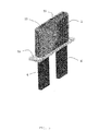
- Fig. 2 shows a schematic side view of a clip 5 similar to Fig. 1 with a container 3 applied to the two head windings arms 6, 6' of the winding.
- the container 3 comprises a rectangular tank created by a bottom and walls 8 at each side of the rectangular container 3 in this example.
- the walls 8 project in the direction above in this perspective.
- the container 3 can be made from a metal, plastic, glass fiber or any other suitable material.
- the container 3 consists of two symmetric parts to be easily assembled to the arms 6, 6' from both sides of the arms 6, 6'.
- the two parts of the container 3 can be connected together with bar clamps, wires, wrapping or other suitable mean for example.
- the container 3 encompasses the arms 6, 6' of the winding to create a tight tank by means of putting a sealing mastic put in all junctions between the container 3 and the arms 6, 6' for gathering a moulding compound 12.
- the sealing mastic is for example a modelling paste, silicone or a clay or other suitable material.
- Fig. 3 shows a schematic side view similar to Fig. 2 with the tightly attached container 3.
- the container 3 is partly filled with the moulding compound 12.
- the filling of the container 3 can be done easily from one of the sides of the container 3.
- the head winding cap 2 is at the below side confined by the moulding compound 12 in container 3 creating a tight connection to the arms 6, 6' through which no dielectric compound 13 can pass as described below.
- a cap 2 is positioned over the clip 5 covering the clip 5 and parts of the head winding arms 6, 6'.
- the term arrangement 1 in the context of this disclosure defines the container 3 and the cap 2 furnished with a hole 15. As described below the cap 2 forms part of the head winding in the later steps as the cap 2 is cast to the head winding 5.
- the lower end of the cap 2 stands on the bottom of the container 3 in contact with the moulding compound 12.
- the cap 2 is made from a fiber glass or other suitable material in this example and shown transparent here for sake of understanding.
- the cap 2 is provided with the hole 15 projecting through the whole thickness of the cap 2 thereby connecting the outside with the inside defined by the cap 2.
- the hole 15 is provided at the top of the cap 2 in this example, further positions of the hole 15 can be realized.
- the hole 15 can be closed in an example of the invention.
- the hole 15 is open during the filling step of the container 3. At this stage a certain time passes to cure and harden the moulding compound 12 depending on the material properties used as moulding compound 12. Only when the moulding compound 12 is cured the next method step is to be executed, as described below.
- a dielectric compound 13 is inserted through the hole 15 inside the space defined by the cap 2 and closed below by the bottom of the container 3 sealed by the cured moulding compound 12.
- the dielectric compound 13 can comprise a variety of materials, also materials with a low viscosity in the contrary to the state of the art.
- the dielectric compound 13 can be chosen from different epoxy types, silicones, urethanes or other suitable dielectric materials.
- the dielectric compound 13 has a good thermal conductivity, a very high insulation resistance, and has a good adhesion to the copper of the arms 6, 6', to the clip 5 and to the insulation material of the cap 2.
- the system reduces intervention time compared to using a conventional filling compound with lower viscosity having to be spooned and finished.
- the described method reduces material management costs as only one type of dielectric compound is applicable for filling the lower and upper caps 2 in the generator, whereas here the upper cap 2 is described.
- the use of low viscosity filling compound reduces the amount of air bubbles in the finished product.
- Dielectric compounds 13 with a viscosity in the range of approximately 3000cps to 20000cps at 20°C can be chosen.
- the dielectric compound 13 flowing down due to high viscosity is stopped by the cured moulding compound 12 in the container 3 of the arrangement 1.
- the arrangement 1 thereby eliminates the risk of the dielectric compound leakage which might lead to pollution of the generator in which the windings are assembled.
- the arrangement 1 furthermore eliminates unnecessary cleaning from leaked material, i.e. dielectric compound 13.
- the filling of the cap 2 can be done with application of high pressure until the whole space defined by the cap 2 and the bottom of the container 3 is filled with dielectric compound 13.
- Dielectric compound 13 with low viscosity allows the use of a pumping station to pump in the dielectric compound 13 through the hole 15. This measure increases the filling speed and improves the repeatability and productivity of the method.
- Another advantage of filling the dielectric compound 13 by a pumping station is the reduction of waste material near to zero.
- the filling method through the hole 15 in the cap 2 does also produce no bubbles in the dielectric compound 13 which impair the properties of the end product.
- the disclosed filling method has a resistance to thermal cycling compared to other methods.
- the dielectric compound 13 is cured and hardened leading to the configuration shown in Fig. 4 and 5 .
- the filling of the cap 2 is shown as a dark area, whereas the cap 2 is shown transparent. In fact it is clear that the cap 2 is not transparent.
- This step of curing can be supported by application of heat or electromagnetic radiation to the cap 2.
- Fig. 4 accordingly shows a schematic side view similar to Fig.
- the head winding cap 2 has the outer contours of the cap 2 and is completely filled with the cured mass encompassing the clip 5 and the upper parts of the head windings arms 6, 6' as is shown in Fig. 4 .
- Fig. 5 shows a schematic side view similar to Fig. 4 with a completed head winding cap 2 fixed to the clip 5.
- the container 3 is removed after the dielectric compound 13 has been fully cured from the configuration together with the cured moulding compound 12.
- alginate or a suitable silicone for moulding compound 12 it can be easily removed leaving no residue.
- the container 3 can be disconnected at the interfaces simply by removing bar clamps or similar measures. A certain manual force has to be applied to the parts of the container 3 to disconnect from the cured material.
- the dielectric compound 13 requires no manual finishing after removing the moulding compound 12. Rather, the method described assures smooth surfaces of the finished head winding cap 2. For the method described there is no application of chemicals required.
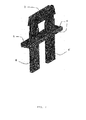
- Fig. 6 shows a perspective view of the head winding cap 2 with arms 6, 6' of the windings from below similar to Fig. 5 .
- the excessive moulding compound 12 around the arms 6, 6' of the winding is removed here.
- Shown is the finished head winding cap 2 with the cap 2 and integrated clip 5 with arms 6, 6' of the winding projecting from the head winding cap 2.
- the part fabricated as described provides a more esthetic appearance as the contours are smooth and leakage of the dielectric compound 13 during manufacturing is essentially avoided.
- the bottom side of the winding head cap 2 has a perfectly flat surface.
- the areas of passage from the arms 6, 6' to the flat bottom side of the head winding cap 2 are neat, i.e. there is an angle of 90 degree between the bottom side and the arms 6, 6' established with a very low deviation.
- the areas of passage from the arms 6, 6' to the flat bottom side of the head winding cap 2 have also no rests of dielectric compound 13 which is merely included within the boundaries of the cap 2.
Landscapes
- Engineering & Computer Science (AREA)
- Power Engineering (AREA)
- Manufacturing & Machinery (AREA)
- Manufacture Of Motors, Generators (AREA)
- Insulation, Fastening Of Motor, Generator Windings (AREA)
- Mechanical Engineering (AREA)
Priority Applications (3)
| Application Number | Priority Date | Filing Date | Title |
|---|---|---|---|
| EP14174783.2A EP2961045A1 (de) | 2014-06-27 | 2014-06-27 | Anordnung zur Herstellung einer Kopfwickelkappe |
| CA2895032A CA2895032C (en) | 2014-06-27 | 2015-06-18 | An arrangement for manufacturing a head winding cap |
| US14/743,342 US10071509B2 (en) | 2014-06-27 | 2015-06-18 | Arrangement for manufacturing a heat winding cap |
Applications Claiming Priority (1)
| Application Number | Priority Date | Filing Date | Title |
|---|---|---|---|
| EP14174783.2A EP2961045A1 (de) | 2014-06-27 | 2014-06-27 | Anordnung zur Herstellung einer Kopfwickelkappe |
Publications (1)
| Publication Number | Publication Date |
|---|---|
| EP2961045A1 true EP2961045A1 (de) | 2015-12-30 |
Family
ID=50982856
Family Applications (1)
| Application Number | Title | Priority Date | Filing Date |
|---|---|---|---|
| EP14174783.2A Withdrawn EP2961045A1 (de) | 2014-06-27 | 2014-06-27 | Anordnung zur Herstellung einer Kopfwickelkappe |
Country Status (3)
| Country | Link |
|---|---|
| US (1) | US10071509B2 (de) |
| EP (1) | EP2961045A1 (de) |
| CA (1) | CA2895032C (de) |
Families Citing this family (1)
| Publication number | Priority date | Publication date | Assignee | Title |
|---|---|---|---|---|
| US9850365B1 (en) | 2016-06-21 | 2017-12-26 | General Electric Company | Electrically insulating composition used in conjunction with dynamoelectric machines |
Citations (5)
| Publication number | Priority date | Publication date | Assignee | Title |
|---|---|---|---|---|
| FR1489751A (fr) | 1966-04-07 | 1967-07-28 | Fives Lille Cail | Perfectionnement à l'isolation des jonctions des sections de bobinage des machines électriques de grande puissance |
| US4151434A (en) | 1976-05-04 | 1979-04-24 | Westinghouse Electric Corp. | Casting assembly for stator coils and method |
| US4621212A (en) | 1984-04-02 | 1986-11-04 | General Electric Company | Stator conductor insulator |
| US4803028A (en) * | 1984-04-02 | 1989-02-07 | General Electric Company | Conductor insulating method |
| US5316801A (en) | 1992-11-25 | 1994-05-31 | General Electric Company | Electrostatic powder coating method for insulating the series loop connections of a dynamoelectric machine |
Family Cites Families (2)
| Publication number | Priority date | Publication date | Assignee | Title |
|---|---|---|---|---|
| DE2836230C2 (de) * | 1978-08-17 | 1982-10-28 | Siemens AG, 1000 Berlin und 8000 München | Verfahren zur Isolierung der gelöteten Stirnverbindungen der Ständerwicklung einer elektrischen Maschine |
| US5142182A (en) * | 1991-06-14 | 1992-08-25 | General Electric Company | Adjustable width caps for insulating series loops on bar wound armatures in electrical systems |
-
2014
- 2014-06-27 EP EP14174783.2A patent/EP2961045A1/de not_active Withdrawn
-
2015
- 2015-06-18 US US14/743,342 patent/US10071509B2/en active Active
- 2015-06-18 CA CA2895032A patent/CA2895032C/en active Active
Patent Citations (5)
| Publication number | Priority date | Publication date | Assignee | Title |
|---|---|---|---|---|
| FR1489751A (fr) | 1966-04-07 | 1967-07-28 | Fives Lille Cail | Perfectionnement à l'isolation des jonctions des sections de bobinage des machines électriques de grande puissance |
| US4151434A (en) | 1976-05-04 | 1979-04-24 | Westinghouse Electric Corp. | Casting assembly for stator coils and method |
| US4621212A (en) | 1984-04-02 | 1986-11-04 | General Electric Company | Stator conductor insulator |
| US4803028A (en) * | 1984-04-02 | 1989-02-07 | General Electric Company | Conductor insulating method |
| US5316801A (en) | 1992-11-25 | 1994-05-31 | General Electric Company | Electrostatic powder coating method for insulating the series loop connections of a dynamoelectric machine |
Also Published As
| Publication number | Publication date |
|---|---|
| CA2895032A1 (en) | 2015-12-27 |
| CA2895032C (en) | 2023-06-20 |
| US20150375432A1 (en) | 2015-12-31 |
| US10071509B2 (en) | 2018-09-11 |
Similar Documents
| Publication | Publication Date | Title |
|---|---|---|
| CN108390510B (zh) | 用于生产电力驱动机的方法以及电力驱动机 | |
| KR101095240B1 (ko) | 분할 고정자 세그먼트 제조 방법 | |
| EP2234248B1 (de) | Verfahren zur herstellung eines geteilten stators | |
| US20160190891A1 (en) | Rotary electric machine stator and manufacturing method of same | |
| JP5505077B2 (ja) | 固定子製造方法 | |
| CN101640440B (zh) | 旋转电机及其制造方法 | |
| CN105960747A (zh) | 旋转电机定子 | |
| EP2571146A2 (de) | Elektromaschinenmodul-Kühlsystem und Herstellungsverfahren | |
| US20150123509A1 (en) | Coil, rotating electrical machine, and method of manufacturing coil | |
| US11336161B2 (en) | Rotating electric machine and method of manufacturing same | |
| US12088163B2 (en) | Stator for an electric machine | |
| CA2895032C (en) | An arrangement for manufacturing a head winding cap | |
| CN109986733A (zh) | 定子的制造方法以及定子 | |
| US11784545B2 (en) | Method of manufacturing stator for rotating electric machine | |
| US4621212A (en) | Stator conductor insulator | |
| CN109882504A (zh) | 磁悬浮轴向轴承组件及具有其的电机 | |
| EP1821389A1 (de) | Isolierkappe für eine Leiterstabverbindung einer Statorwicklung | |
| CN109245349B (zh) | 空心杯电机转子及制作方法 | |
| JP2014039345A (ja) | 回転電機のステータの製造方法 | |
| CN109314450A (zh) | 电动机的制造方法、电动机的制造装置、树脂密封夹具及电动机 | |
| CN117099288A (zh) | 用于旋转电机的定子 | |
| JP2012164535A (ja) | 線材と撚り線の接続方法及びそれを用いた回転電機 | |
| US3436811A (en) | Method for encapsulating dynamoelectric machine stators using a conformable sleeve | |
| JP2012235597A (ja) | ステータコアにセグメントコイルを形成する方法 | |
| CN219513943U (zh) | 一种永磁直流无刷电机后端盖组件灌封模具 |
Legal Events
| Date | Code | Title | Description |
|---|---|---|---|
| PUAI | Public reference made under article 153(3) epc to a published international application that has entered the european phase |
Free format text: ORIGINAL CODE: 0009012 |
|
| 17P | Request for examination filed |
Effective date: 20140627 |
|
| AK | Designated contracting states |
Kind code of ref document: A1 Designated state(s): AL AT BE BG CH CY CZ DE DK EE ES FI FR GB GR HR HU IE IS IT LI LT LU LV MC MK MT NL NO PL PT RO RS SE SI SK SM TR |
|
| AX | Request for extension of the european patent |
Extension state: BA ME |
|
| RIC1 | Information provided on ipc code assigned before grant |
Ipc: H02K 5/12 20060101ALI20161031BHEP Ipc: H02K 15/12 20060101ALI20161031BHEP Ipc: H02K 3/38 20060101AFI20161031BHEP |
|
| GRAP | Despatch of communication of intention to grant a patent |
Free format text: ORIGINAL CODE: EPIDOSNIGR1 |
|
| INTG | Intention to grant announced |
Effective date: 20161214 |
|
| STAA | Information on the status of an ep patent application or granted ep patent |
Free format text: STATUS: THE APPLICATION IS DEEMED TO BE WITHDRAWN |
|
| 18D | Application deemed to be withdrawn |
Effective date: 20170425 |