EP2961041A2 - Motor - Google Patents
Motor Download PDFInfo
- Publication number
- EP2961041A2 EP2961041A2 EP15156527.2A EP15156527A EP2961041A2 EP 2961041 A2 EP2961041 A2 EP 2961041A2 EP 15156527 A EP15156527 A EP 15156527A EP 2961041 A2 EP2961041 A2 EP 2961041A2
- Authority
- EP
- European Patent Office
- Prior art keywords
- rotor
- core
- holder
- magnet
- rotor core
- Prior art date
- Legal status (The legal status is an assumption and is not a legal conclusion. Google has not performed a legal analysis and makes no representation as to the accuracy of the status listed.)
- Withdrawn
Links
- 230000005291 magnetic effect Effects 0.000 claims abstract description 52
- 230000005294 ferromagnetic effect Effects 0.000 claims abstract description 8
- 229910000576 Laminated steel Inorganic materials 0.000 claims abstract description 7
- 239000000853 adhesive Substances 0.000 claims description 3
- 230000001070 adhesive effect Effects 0.000 claims description 3
- 229910000831 Steel Inorganic materials 0.000 description 18
- 239000010959 steel Substances 0.000 description 18
- 230000004048 modification Effects 0.000 description 16
- 238000012986 modification Methods 0.000 description 16
- 230000004907 flux Effects 0.000 description 15
- 238000005452 bending Methods 0.000 description 9
- 239000012212 insulator Substances 0.000 description 6
- 239000000463 material Substances 0.000 description 5
- 230000009467 reduction Effects 0.000 description 3
- 238000002788 crimping Methods 0.000 description 2
- -1 for example Substances 0.000 description 2
- 238000010030 laminating Methods 0.000 description 2
- 238000000034 method Methods 0.000 description 2
- 230000000087 stabilizing effect Effects 0.000 description 2
- 229910001335 Galvanized steel Inorganic materials 0.000 description 1
- 230000003247 decreasing effect Effects 0.000 description 1
- 230000006866 deterioration Effects 0.000 description 1
- 229910003460 diamond Inorganic materials 0.000 description 1
- 239000010432 diamond Substances 0.000 description 1
- 239000003302 ferromagnetic material Substances 0.000 description 1
- 239000012530 fluid Substances 0.000 description 1
- 239000008397 galvanized steel Substances 0.000 description 1
- 230000003993 interaction Effects 0.000 description 1
- WABPQHHGFIMREM-UHFFFAOYSA-N lead(0) Chemical compound [Pb] WABPQHHGFIMREM-UHFFFAOYSA-N 0.000 description 1
- 238000004519 manufacturing process Methods 0.000 description 1
- 230000007246 mechanism Effects 0.000 description 1
- 239000002184 metal Substances 0.000 description 1
- 239000011347 resin Substances 0.000 description 1
- 229920005989 resin Polymers 0.000 description 1
- 239000010935 stainless steel Substances 0.000 description 1
- 229910001220 stainless steel Inorganic materials 0.000 description 1
Images



Classifications
-
- H—ELECTRICITY
- H02—GENERATION; CONVERSION OR DISTRIBUTION OF ELECTRIC POWER
- H02K—DYNAMO-ELECTRIC MACHINES
- H02K11/00—Structural association of dynamo-electric machines with electric components or with devices for shielding, monitoring or protection
- H02K11/20—Structural association of dynamo-electric machines with electric components or with devices for shielding, monitoring or protection for measuring, monitoring, testing, protecting or switching
- H02K11/21—Devices for sensing speed or position, or actuated thereby
- H02K11/215—Magnetic effect devices, e.g. Hall-effect or magneto-resistive elements
-
- H—ELECTRICITY
- H02—GENERATION; CONVERSION OR DISTRIBUTION OF ELECTRIC POWER
- H02K—DYNAMO-ELECTRIC MACHINES
- H02K1/00—Details of the magnetic circuit
- H02K1/06—Details of the magnetic circuit characterised by the shape, form or construction
- H02K1/22—Rotating parts of the magnetic circuit
- H02K1/27—Rotor cores with permanent magnets
- H02K1/2706—Inner rotors
- H02K1/272—Inner rotors the magnetisation axis of the magnets being perpendicular to the rotor axis
- H02K1/2726—Inner rotors the magnetisation axis of the magnets being perpendicular to the rotor axis the rotor consisting of a single magnet or two or more axially juxtaposed single magnets
- H02K1/2733—Annular magnets
-
- H—ELECTRICITY
- H02—GENERATION; CONVERSION OR DISTRIBUTION OF ELECTRIC POWER
- H02K—DYNAMO-ELECTRIC MACHINES
- H02K1/00—Details of the magnetic circuit
- H02K1/06—Details of the magnetic circuit characterised by the shape, form or construction
- H02K1/12—Stationary parts of the magnetic circuit
- H02K1/16—Stator cores with slots for windings
-
- H—ELECTRICITY
- H02—GENERATION; CONVERSION OR DISTRIBUTION OF ELECTRIC POWER
- H02K—DYNAMO-ELECTRIC MACHINES
- H02K1/00—Details of the magnetic circuit
- H02K1/06—Details of the magnetic circuit characterised by the shape, form or construction
- H02K1/22—Rotating parts of the magnetic circuit
- H02K1/28—Means for mounting or fastening rotating magnetic parts on to, or to, the rotor structures
- H02K1/30—Means for mounting or fastening rotating magnetic parts on to, or to, the rotor structures using intermediate parts, e.g. spiders
-
- H—ELECTRICITY
- H02—GENERATION; CONVERSION OR DISTRIBUTION OF ELECTRIC POWER
- H02K—DYNAMO-ELECTRIC MACHINES
- H02K29/00—Motors or generators having non-mechanical commutating devices, e.g. discharge tubes or semiconductor devices
- H02K29/06—Motors or generators having non-mechanical commutating devices, e.g. discharge tubes or semiconductor devices with position sensing devices
-
- H—ELECTRICITY
- H02—GENERATION; CONVERSION OR DISTRIBUTION OF ELECTRIC POWER
- H02K—DYNAMO-ELECTRIC MACHINES
- H02K29/00—Motors or generators having non-mechanical commutating devices, e.g. discharge tubes or semiconductor devices
- H02K29/06—Motors or generators having non-mechanical commutating devices, e.g. discharge tubes or semiconductor devices with position sensing devices
- H02K29/08—Motors or generators having non-mechanical commutating devices, e.g. discharge tubes or semiconductor devices with position sensing devices using magnetic effect devices, e.g. Hall-plates, magneto-resistors
Definitions
- the present invention relates to a motor.
- An effective way to prevent a bending of the shaft is to arrange a rotor core around the shaft.
- the rotor magnet is arranged to project toward a circuit board relative to a stator core (see FIG. 1 of JP-A 2013-99094 ).
- the circuit board has mounted thereon magnetic sensors used to detect the circumferential position of the rotor magnet, it is necessary to ensure that the magnetic sensors are able to detect the circumferential position of the rotor magnet with sufficient precision. This requires some contrivance to be applied, such as reducing the distance between the circuit board and the rotor magnet as in the motor described in JP-A 2013-99094 .
- a motor includes a stationary portion and a rotating portion arranged to rotate about a rotation axis extending in a vertical direction.
- the rotating portion includes a shaft arranged to extend along the rotation axis, and a rotor arranged to rotate together with the shaft.
- the stationary portion includes a stator arranged radially outside of the rotor, and a magnetic sensor arranged above the rotor to detect a rotational position of the rotor.
- the rotor includes a tubular rotor core being a ferromagnetic body and fixed to the shaft; a rotor magnet arranged radially outside of the rotor core and under the magnetic sensor, arranged to be in contact with the rotor core or arranged opposite to the rotor core with a first gap intervening therebetween, and including an upper end surface arranged at a level higher than that of an upper end surface of the rotor core; and at least one rotor holder being a ferromagnetic body, and arranged above the rotor core and radially inside of the rotor magnet.
- the rotor core is defined by laminated steel sheets placed one upon another in an axial direction.
- the rotor holder includes an outer cylindrical portion arranged to be in contact with the rotor magnet or arranged opposite to the rotor magnet with a second gap intervening therebetween.
- an axial direction is a vertical direction
- a side on which a magnetic sensor is arranged with respect to a rotor is defined as an upper side.
- the shape of each member or portion and relative positions of different members or portions will be described based on the above assumptions. It should be noted, however, that the above definitions of the vertical direction and the upper and lower sides are made simply for the sake of convenience in description, and should not be construed to restrict in any way the orientation of a motor according to any preferred embodiment of the present invention when in use.
- FIG. 1 is a cross-sectional view of the motor 1A. As illustrated in FIG. 1 , the motor 1A includes a stationary portion 2A and a rotating portion 3A.
- the stationary portion 2A includes a stator 23A and magnetic sensors 241A.
- the stator 23A is an armature arranged radially outside of a rotor 32A of the rotating portion 3A.
- the rotor 32A will be described below.
- the magnetic sensors 241A are arranged above the rotor 32A described below to detect the rotational position of the rotor 32A.
- the magnetic sensors 241A are arranged over a rotor magnet 322A described below.
- the magnetic sensors 241A detect the circumferential position of the rotor magnet 322A by detecting magnetic flux passing from the rotor magnet 322A toward each magnetic sensor 241A.
- the rotating portion 3A is supported to be rotatable about a rotation axis 9A with respect to the stationary portion 2A.
- the rotating portion 3A is thus arranged to rotate about the rotation axis 9A.
- the rotating portion 3A includes a shaft 31A and the rotor 32A.
- the shaft 31A is a columnar member arranged to extend along the rotation axis 9A.
- the rotor 32A is arranged to rotate together with the shaft 31A.
- the rotor 32A includes a rotor core 321 A, the rotor magnet 322A, and a rotor holder 323A.
- the rotor core 321A is a tubular member being a ferromagnetic body and fixed to the shaft 31A.
- the rotor core 321A is defined by laminated steel sheets, i.e., a plurality of steel sheets placed one upon another in the axial direction.
- the rotor core 321A is arranged around the shaft 31A to increase rigidity of the rotor 32A including the shaft 31A. This contributes to preventing a bending of the shaft 31A while the motor 1 A is running. This in turn contributes to reducing vibrations and noise of the motor 1A.
- the rotor magnet 322A is an annular magnet. An outer circumferential surface of the rotor magnet 322A is arranged radially opposite to an inner circumferential surface of the stator core 231A. The outer circumferential surface of the rotor magnet 322A includes north and south poles arranged to alternate with each other in a circumferential direction. Note that a plurality of magnets may be used in place of the rotor magnet 322A.
- the rotor magnet 322A is arranged under the magnetic sensors 241 A.
- the rotor magnet 322A is arranged radially outside of the rotor core 321A.
- the rotor magnet 322A and the rotor core 321A are arranged to be in contact with each other. That is, a radial distance from the rotation axis 9A to an inner circumferential surface of the rotor magnet 322A and a radial distance from the rotation axis 9A to an outer circumferential surface of the rotor core 321A are equal to each other. Note that the above two radial distances may be not exactly but substantially equal to each other.
- this gap is referred to as a first gap.
- the first gap is narrow enough to allow the rotor core 321A to function as a back yoke for the rotor magnet 322A.
- An upper end surface of the rotor magnet 322A is arranged at a level higher than that of an upper end surface of the rotor core 321A.
- the axial distance between the rotor magnet 322A and each magnetic sensor 241A is reduced. This enables the magnetic sensors 241A to detect the circumferential position of the rotor magnet 322A with higher precision.
- the rotor holder 323A is arranged above the rotor core 321A and radially inside of the rotor magnet 322A.
- the rotor holder 323A is a ferromagnetic body.
- the rotor holder 323A includes a substantially cylindrical outer cylindrical portion 61A arranged to extend along the rotation axis 9A.
- the outer cylindrical portion 61A may be either arranged to be in contact with the rotor magnet 322A or arranged radially opposite to the rotor magnet 322A with a gap intervening therebetween. In the case where the outer cylindrical portion 61A and the rotor magnet 322A are arranged opposite to each other with the gap intervening therebetween, this gap is referred to as a second gap. In this case, the second gap is narrow enough to allow the outer cylindrical portion 61A to function as a back yoke for the rotor magnet 322A.
- the rotor holder 323A functions as the back yoke for the rotor magnet 322A. Consequently, even in the case where the rotor magnet 322A is arranged to project upward above the upper end surface of the rotor core 321A, magnetic flux is reduced only to a limited degree at a projecting portion of the rotor magnet 322A. Accordingly, a reduction in the magnetic flux passing from the rotor magnet 322A toward each magnetic sensor 241A is reduced. This contributes to further improving the precision with which the circumferential position of the rotor magnet 322A is detected by the magnetic sensors 241 A.
- the motor 1A since the rotor holder 323A functions as the back yoke, it is not necessary to extend the rotor core 321A up to a vicinity of an upper end portion of the rotor magnet 322A. This reduces an increase in the weight of the motor 1A owing to the weight of the rotor core 321A.
- the motor 1A according to the present preferred embodiment is able to reduce the possibility of a bending of the shaft 31A, and also to achieve improved precision with which the circumferential position of the rotor magnet 322A is detected by the magnetic sensors 241A while reducing an increase in the weight of the motor 1A.
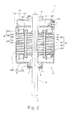
- FIG. 2 is a cross-sectional view of the motor 1.
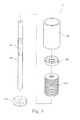
- FIG. 3 is an exploded perspective view of a rotating portion 3 of the motor 1.
- FIG. 4 is a partial cross-sectional view of the motor 1.
- the motor 1 is used, for example, in a blower to provide rotational power to rotate an impeller of the blower.
- the motor 1 includes a stationary portion 2, the rotating portion 3, and a bearing portion 4.
- the stationary portion 2 includes a housing 21, a cap 22, a stator 23, and a circuit board 24.
- the housing 21 includes a housing bottom portion 211, a housing tubular portion 212, and a first bearing holding portion 213.
- the housing bottom portion 211 is arranged to be perpendicular or substantially perpendicular to a rotation axis 9.
- the housing tubular portion 212 is tubular, and is arranged to extend axially upward from the housing bottom portion 211 along the rotation axis 9.
- the first bearing holding portion 213 is arranged to project downward from the housing bottom portion 211.
- An outer circumferential surface of a lower ball bearing 41, which will be described below, of the bearing portion 4 is fixed inside the first bearing holding portion 213.
- the cap 22 includes a cap bottom portion 221, a cap tubular portion 222, and a second bearing holding portion 223.
- the cap bottom portion 221 is arranged to be perpendicular or substantially perpendicular to the rotation axis 9.
- the cap tubular portion 222 is tubular, and is arranged to extend axially downward from the cap bottom portion 221 along the rotation axis 9.
- the second bearing holding portion 223 is arranged to project upward from the cap bottom portion 221.
- An outer circumferential surface of an upper ball bearing 42, which will be described below, of the bearing portion 4 is fixed inside the second bearing holding portion 223.
- the stator 23, at least a portion of the circuit board 24, and a rotor 32 of the rotating portion 3 are accommodated inside a case defined by the housing 21 and the cap 22.
- the rotor 32 will be described below.
- Each of the housing 21 and the cap 22 is made of, for example, a galvanized steel sheet, SUS, or the like.
- the housing 21 and the cap 22 according to the present preferred embodiment are made of the same material. Note that the housing 21 and the cap 22 may be made of different materials.
- the stator 23 is an armature defined by a stator core 231, an insulator 232, and coils 233.
- the stator 23 is arranged radially outside of the rotor 32.
- the stator core 231 is defined by electromagnetic steel sheets placed one upon another in an axial direction.
- the stator core 231 includes an annular core back 51 and a plurality of teeth 52 arranged to project radially inward from the core back 51.
- An outer circumferential surface of the core back 51 is fixed to an inner circumferential surface of the housing tubular portion 212.
- the plurality of teeth 52 are arranged at substantially regular intervals in a circumferential direction.
- the insulator 232 is a member made of a resin and arranged to cover a portion of a surface of the stator core 231.
- the insulator 232 according to the present preferred embodiment includes a cover portion 53 arranged to cover an upper end surface of the stator core 231, and a board support portion 54 arranged to project upward from the cover portion 53.
- Each of the coils 233 is wound around a separate one of the teeth 52 with the insulator 232 intervening therebetween.
- Each coil 233 is defined by a conducting wire wound around a corresponding one of the teeth 52 with the insulator 232 intervening therebetween.
- the circuit board 24 is arranged to supply electric drive currents to the coils 233 of the stator 23.
- the circuit board 24 according to the present preferred embodiment is arranged in a space enclosed by the housing 21 and the cap 22.
- the circuit board 24 is fixed to the board support portion 54 of the insulator 232.
- Magnetic sensors 241 arranged above the rotor 32 to detect the rotational position of the rotor 32 are arranged on a lower surface of the circuit board 24.
- the magnetic sensors 241 detect the rotational position of the rotor 32 by detecting the circumferential position of a rotor magnet 322 described below.
- Each magnetic sensor 241 is, for example, a Hall element.
- the number of magnetic sensors 241 is three, and the three magnetic sensors 241 are spaced from one another by sixty degrees about the rotation axis 9.
- the magnetic sensors 241 detect the circumferential position of the rotor magnet 322, and perform feedback to enable appropriate drive control of the motor 1.
- the cap tubular portion 222 of the cap 22 includes a cut 220 passing through the cap tubular portion 222 in a radial direction.
- a portion of a lead wire 242 connected to the circuit board 24 is arranged in the cut 220.
- a portion of the circuit board 24 or a connector may be arranged in the cut 220.
- the cap 22 may include a hole passing through the cap tubular portion 222 in a radial direction in place of the cut 220.
- the circuit board 24 is electrically connected to an external device through the cut 220 to enable electric drive currents necessary to drive the motor 1 to be supplied to the circuit board 24.
- the rotating portion 3 is supported to be rotatable about the rotation axis 9 with respect to the stationary portion 2.
- the rotating portion 3 according to the present preferred embodiment includes a shaft 31 and the rotor 32.
- the shaft 31 is a columnar member extending along the rotation axis 9.
- a metal such as, for example, stainless steel, is used as a material of the shaft 31.
- the shaft 31 is arranged to rotate about the rotation axis 9 while being supported by the bearing portion 4.
- a lower end portion of the shaft 31 is arranged to project downward below the housing 21.
- the lower end portion of the shaft 31 is fixed to an object which is to be driven by the motor 1, such as, for example, the impeller of the blower.
- An outer circumferential surface of the shaft 31 includes a press fit portion 311 to which a rotor core 321 described below is press fitted.
- the press fit portion 311 is knurled to fix the rotor core 321 thereto with increased strength.
- the press fit portion 311 is knurled in a linear pattern with straight ridges extending along the rotation axis 9 according to the present preferred embodiment, but may alternatively be knurled in a crisscross pattern, e.g., a diamond pattern or a square or rectangular pattern, or in a diagonal pattern. Also note that knurling may not necessarily be applied to the shaft 31.
- the rotor 32 includes the rotor core 321, the rotor magnet 322, a first rotor holder 323, and a second rotor holder 324.
- the rotor 32 is arranged to rotate together with the shaft 31.
- the rotor core 321 is cylindrical and is defined by electromagnetic steel sheets placed one upon another in the axial direction. That is, the rotor core 321 is a ferromagnetic body. An inner circumferential surface of the rotor core 321 is fixed to the shaft 31 through press fitting. The rotor core 321 is arranged around the shaft 31 to increase rigidity of the shaft 31. This contributes to preventing a bending of the shaft 31 while the motor 1 is running. This in turn contributes to reducing vibrations and noise of the motor 1.
- the stator core 231 is arranged to have an axial dimension equal to the axial dimension of the rotor core 321. Accordingly, the steel sheets which define the stator core 231 and the steel sheets which define the rotor core 321 can be stamped from the same steel sheet. Specifically, the steel sheets of the rotor core 321 are stamped out from portions of the steel sheet which are radially inside of portions of the steel sheet from which the steel sheets of the stator core 231 are stamped out. Thus, material costs of the stator core 231 and the rotor core 321 are reduced, and scraps are also reduced.
- the rotor magnet 322 is an annular magnet centered on the rotation axis 9.
- the rotor magnet 322 is arranged radially outside of the rotor core 321 and under the magnetic sensors 241, and is arranged to rotate together with the shaft 31.
- An outer circumferential surface of the rotor magnet 322 is arranged radially opposite to an inner end of each of the plurality of teeth 52 of the stator core 231.
- the outer circumferential surface of the rotor magnet 322 includes north and south poles arranged to alternate with each other in the circumferential direction.
- a plurality of magnets may be used. In this case, the plurality of magnets are arranged in the circumferential direction such that north and south pole surfaces alternate with each other.
- an inner circumferential surface of the rotor magnet 322 is arranged radially opposite to the rotor core 321 with a first gap 71 intervening therebetween.
- the first gap 71 is narrow enough to allow the rotor core 321 to function as a back yoke for the rotor magnet 322. This contributes to increasing magnetic flux which passes from the rotor magnet 322 toward the stator core 231 at a position opposed to the stator core 231.
- a torque characteristic of the motor 1 is improved.
- an outer circumferential surface of the rotor core 321 and the inner circumferential surface of the rotor magnet 322 are fixed to each other through adhesion.
- an adhesive P is arranged in the first gap 71.
- the upper end surface of the rotor magnet 322 is arranged at a level higher than that of an upper end surface of the rotor core 321.
- the axial distance between the rotor magnet 322 and each magnetic sensor 241 is reduced. This enables the magnetic sensors 241 to detect the circumferential position of the rotor magnet 322 with higher precision.
- a lower end surface of the rotor magnet 322 is arranged at a level lower than that of a lower end surface of the rotor core 321.
- the axial dimension of a portion of the rotor magnet 322 which is above the upper end surface of the rotor core 321 is substantially equal to the axial dimension of a portion of the rotor magnet 322 which is below the lower end surface of the rotor core 321. Accordingly, magnetic flux originating from the rotor magnet 322 is distributed in a balanced manner above and below an axial middle of the stator 23.
- Each of the first rotor holder 323 and the second rotor holder 324 is made of a ferromagnetic material, such as, for example, steel.
- Each of the first rotor holder 323 and the second rotor holder 324 according to the present preferred embodiment is a stamping, i.e., an article obtained by subjecting a sheet material to press working.
- a production cost of each of the first rotor holder 323 and the second rotor holder 324 is reduced compared to the case where each of the first rotor holder 323 and the second rotor holder 324 is manufactured by another method, such as, for example, laminating steel sheets.
- the first rotor holder 323 is arranged above the rotor core 321.
- the second rotor holder 324 is arranged below the rotor core 321.
- each of the first rotor holder 323 and the second rotor holder 324 is arranged radially inside of the rotor magnet 322.
- the second rotor holder 324 is arranged to have substantially the same shape as that of the first rotor holder 323, and the first and second rotor holders 323 and 324 are arranged upside down relative to each other. That is, the first rotor holder 323 and the second rotor holder 324 are arranged to be symmetric with respect to a horizontal plane.
- the second rotor holder 324 is similar to the first rotor holder 323 in the shape, dimensions, and so on, and descriptions thereof are therefore omitted.
- the first rotor holder 323 includes an outer cylindrical portion 61, an inner cylindrical portion 62, and an annular plate portion 63.
- Each of the outer cylindrical portion 61 and the inner cylindrical portion 62 is a substantially cylindrical portion arranged to extend along the rotation axis 9.
- the outer cylindrical portion 61 is arranged to extend along the inner circumferential surface of the rotor magnet 322.
- the outer cylindrical portion 61 is arranged radially opposite to the inner circumferential surface of the rotor magnet 322 with a second gap 72 intervening therebetween.
- the second gap 72 is narrow enough to allow the outer cylindrical portion 61 to function as a back yoke for the rotor magnet 322.
- the inner circumferential surface of the rotor magnet 322 and an outer circumferential surface of the first rotor holder 323 are fixed to each other through adhesion. Therefore, the adhesive P is arranged in the second gap 72.
- the first rotor holder 323 functions as the back yoke for the rotor magnet 322. Consequently, even in the case where the rotor magnet 322 is arranged to project upward above the upper end surface of the rotor core 321, magnetic flux is reduced only to a limited degree at a projecting portion of the rotor magnet 322. Accordingly, a reduction in the magnetic flux passing from the rotor magnet 322 toward each magnetic sensor 241 is reduced. This contributes to further improving the precision with which the circumferential position of the rotor magnet 322 is detected by the magnetic sensors 241.
- the radial width of the first gap 71 corresponds to a difference between a radial distance r1 from the rotation axis 9 to the inner circumferential surface of the rotor magnet 322 and a radial distance r2 from the rotation axis 9 to the outer circumferential surface of the rotor core 321.
- the radial width of the second gap 72 corresponds to a difference between the radial distance r1 from the rotation axis 9 to the inner circumferential surface of the rotor magnet 322 and a radial distance r3 from the rotation axis 9 to the outer circumferential surface of the first rotor holder 323.
- the radial distance r3 from the rotation axis 9 to the outer circumferential surface of the first rotor holder 323 is equal to or smaller than the radial distance r2 from the rotation axis 9 to the outer circumferential surface of the rotor core 321. That is, the radial width of the first gap 71 is smaller than the radial width of the second gap 72.
- the rotor core 321 is defined by laminating the stamped electromagnetic steel sheets in the axial direction. Meanwhile, the first rotor holder 323 is molded by press working. Therefore, radial dimensional accuracy of the rotor core 321 is higher than radial dimensional accuracy of the first rotor holder 323. Accordingly, the radial width of the first gap 71 is arranged to be smaller than the radial width of the second gap 72 to increase accuracy with which the rotor magnet 322 is positioned with respect to the rotation axis 9. As a result, the rotor magnet 322 is more easily arranged to be coaxial with the rotation axis 9.
- the rotor core 321 functions as the back yoke for the rotor magnet 322 more effectively than the first rotor holder 323. This contributes to further increasing magnetic flux which passes from the rotor magnet 322 toward the stator core 231 at the position opposed to the stator core 231. As a result, the torque characteristic of the motor 1 is further improved.
- the axial position of the upper end surface of the rotor magnet 322 and the axial position of an upper end surface of the outer cylindrical portion 61 of the first rotor holder 323 are identical to each other. That is, the axial position of the upper end surface of the rotor magnet 322 and the axial position of an upper end surface of a portion of the first rotor holder 323 which is adjacent to the rotor magnet 322 are identical to each other. This contributes to further increasing magnetic flux passing from a vicinity of an upper end portion of the rotor magnet 322 toward each magnetic sensor 241. This enables the magnetic sensors 241 to detect the circumferential position of the rotor magnet 322 with still higher precision. Note that the above two axial positions may be not exactly but substantially identical to each other.
- the annular plate portion 63 is a portion which joins a lower end portion of the outer cylindrical portion 61 and a lower end portion of the inner cylindrical portion 62 to each other.
- a gap is defined between a lower end surface of the first rotor holder 323, that is, a lower end surface of the annular plate portion 63, and the upper end surface of the rotor core 321.
- the rotor core 321 and the first rotor holder 323 do not restrict the axial position of each other.
- a variation in the axial dimension of the rotor core 321 or of the first rotor holder 323 would not prevent the rotor core 321 and the first rotor holder 323 from being arranged at their respective appropriate axial positions.
- This allows, for example, the position of an axial middle of the rotor core 321, the position of an axial middle of the rotor magnet 322, and the position of an axial midpoint between the first rotor holder 323 and the second rotor holder 324 to coincide with one another.
- the inner cylindrical portion 62 is fixed to the shaft 31.
- the first rotor holder 323 is fixed to the shaft 31 as a result of an inner circumferential surface of the inner cylindrical portion 62 of the first rotor holder 323 being press fitted to the outer circumferential surface of the shaft 31.
- a radially inner end portion of the first rotor holder 323 is arranged to be in contact with the outer circumferential surface of the shaft 31.
- the second rotor holder 324 is also fixed to the shaft 31 through press fitting in a manner similar to that in which the first rotor holder 323 is fixed to the shaft 31.
- the first rotor holder 323 is molded by press working, a tapered portion which becomes radially more distant from the rotor magnet 322 with decreasing distance from an axial end portion thereof is defined at a junction of the annular plate portion 63 and the outer cylindrical portion 61. Therefore, if the annular plate portion 63 were arranged to be joined to an upper end portion of the outer cylindrical portion 61, the radial width of the second gap 72 would increase at a position radially inside the upper end portion of the rotor magnet 322. This would make the function of the first rotor holder 323 as the back yoke for the vicinity of the upper end portion of the rotor magnet 322 less effective.
- the annular plate portion 63 is arranged to be joined to the lower end portion of the outer cylindrical portion 61 to allow the radial distance between the outer cylindrical portion 61 and the rotor magnet 322 to be substantially uniform in the vicinity of the upper end portion of the outer cylindrical portion 61. This contributes to preventing the function of the first rotor holder 323 as the back yoke for the vicinity of the upper end portion of the rotor magnet 322 from becoming less effective. This in turn contributes to preventing a reduction in the precision with which the circumferential position of the rotor magnet 322 is detected by the magnetic sensors 241.
- the bearing portion 4 includes the lower ball bearing 41 and the upper ball bearing 42. As described above, the outer circumferential surfaces of the lower ball bearing 41 and the upper ball bearing 42 are fixed to the housing 21 and the cap 22, respectively. In addition, an inner circumferential surface of each of the lower ball bearing 41 and the upper ball bearing 42 is fixed to the outer circumferential surface of the shaft 31. The bearing portion 4 is thus arranged to rotatably support the shaft 31. Note that, although the bearing portion 4 according to the present preferred embodiment is defined by ball bearings, this is not essential to the present invention. The bearing portion 4 may alternatively be defined by a bearing mechanism of another type, such as, for example, a plain bearing or a fluid bearing.
- the rotor core 321 is arranged around the shaft 31 to prevent a bending of the shaft 31. Moreover, since the first rotor holder 323 functions as the back yoke, it is not necessary to extend the rotor core 321 up to the vicinity of the upper end portion of the rotor magnet 322. This contributes to improving the precision with which the circumferential position of the rotor magnet 322 is detected by the magnetic sensors 241 while reducing an increase in the weight of the motor 1.
- FIG. 5 is a partial cross-sectional view of a motor 1 B according to a modification of the above-described preferred embodiment.
- a radial distance r2 from a rotation axis 9B to an outer circumferential surface of a rotor core 321 B is equal to or smaller than a radial distance r3 from the rotation axis 9B to an outer circumferential surface of a first rotor holder 323B.
- the radial width of a first gap 71 B corresponds to a difference between a radial distance r1 from the rotation axis 9B to an inner circumferential surface of a rotor magnet 322B and the radial distance r2 from the rotation axis 9B to the outer circumferential surface of the rotor core 321 B.
- the radial width of a second gap 72B corresponds to a difference between the radial distance r1 from the rotation axis 9B to the inner circumferential surface of the rotor magnet 322B and the radial distance r3 from the rotation axis 9B to the outer circumferential surface of the first rotor holder 323B.
- the radial width of the second gap 72B which is a radial gap between the rotor magnet 322B and the first rotor holder 323B, is equal to or smaller than the radial width of the first gap 71 B, which is a radial gap between the rotor magnet 322B and the rotor core 321B.
- FIG. 6 is a partial cross-sectional view of a motor 1C according to another modification of the above-described preferred embodiment.
- a first rotor holder 323C is a cylindrical member arranged to extend along a rotation axis 9C.
- the first rotor holder 323C includes only an outer cylindrical portion 61C arranged opposite to a rotor magnet 322C with a second gap 72C intervening therebetween.
- a rotor core 321C includes a recessed portion 320C recessed from each of an upper end surface and an outer circumferential surface of the rotor core 321C.
- An inner circumferential surface of a lower end portion of the first rotor holder 323C is press fitted to a radially inner surface of the recessed portion 320C, whereby the first rotor holder 323C is fixed to the rotor core 321C.
- a back yoke is arranged such that a gap between an outer circumferential surface of the back yoke and an inner circumferential surface of the rotor magnet 322C has a uniform or substantially uniform width from an axially upper end to an axially lower end thereof. This contributes to stabilizing magnetic flux passing from a surface of the rotor magnet 322C to a surrounding space.
- FIG. 7 is a partial cross-sectional view of a motor 1 D according to another modification of the above-described preferred embodiment.
- a first rotor holder 323D is defined by laminated steel sheets, just as a rotor core 321 D is defined by laminated steel sheets.
- the first rotor holder 323D includes only an outer cylindrical portion 61 D arranged opposite to a rotor magnet 322D with a second gap 72D intervening therebetween.
- the steel sheet arranged at a lower end of the first rotor holder 323D and the steel sheet arranged at an upper end of the rotor core 321 D are fixed to each other by crimping or the like, just as axially adjacent ones of the steel sheets within the rotor core 321 D are fixed to each other by crimping or the like.
- each of the steel sheets which define the rotor core 321 D and each of the steel sheets which define the first rotor holder 323D are both molded by stamping. Accordingly, the rotor core 321 D and the first rotor holder 323D are equivalent in radial dimensional accuracy.
- a radial distance r2 from a rotation axis 9D to an outer circumferential surface of the rotor core 321 D and a radial distance r3 from the rotation axis 9D to an outer circumferential surface of the first rotor holder 323D are equal or substantially equal to each other than it is to define the rotor core 321C and the first rotor holder 323C such that the radial distance r2 from the rotation axis 9C to the outer circumferential surface of the rotor core 321C and the radial distance r3 from the rotation axis 9C to the outer circumferential surface of the first rotor holder 323C are equal or substantially equal to each other in the modification illustrated in FIG. 6 .
- a back yoke is arranged such that a gap between an outer circumferential surface of the back yoke and an inner circumferential surface of the rotor magnet 322D has a uniform width from an axially upper end to an axially lower end thereof. This contributes to further stabilizing magnetic flux passing from a surface of the rotor magnet 322D to a surrounding space.
- the rotor holder is fixed to the shaft in the above-described preferred embodiment, this is not essential to the present invention.
- the rotor holder may be fixed to the rotor core.
- the rotor holder and the rotor core may be fixed to each other by any other desirable fixing method, such as, for example, adhesion.
- it may be so arranged that a raised portion and a recessed portion are defined in a lower end surface of the rotor holder and an upper end surface of the rotor core, respectively, and the raised portion and the recessed portion are mated and crimped together to fix the rotor holder and the rotor core to each other.
- motors according to the above-described preferred embodiment of the present invention are used in the blower.
- motors according to other preferred embodiments of the present invention may be used, for example, in office automation appliances, such as printers and copy machines, transportation equipment, such as automobiles, household electrical appliances, medical appliances, disk drives, blower fans, and the like to generate a variety of driving forces.
- Preferred embodiments of the present invention are applicable to, for example, motors.
Landscapes
- Engineering & Computer Science (AREA)
- Power Engineering (AREA)
- Microelectronics & Electronic Packaging (AREA)
- Iron Core Of Rotating Electric Machines (AREA)
- Permanent Field Magnets Of Synchronous Machinery (AREA)
Abstract
Description
- The present invention relates to a motor.
- In a so-called inner-rotor motor, in which a rotating shaft and a rotor magnet are arranged radially inside of an armature, a bending of the shaft tends to occur more easily with an increasing rotational speed of the motor. A bending of the shaft may cause vibrations and noise of the motor as a whole, In recent years, due to an increase in the rotational speed of motors, there has been a demand for preventing a bending of the shaft. A known inner-rotor motor is described, for example, in
JP-A 2013-99094 - In the motor described in
JP-A 2013-99094 FIG. 1 ofJP-A 2013-99094 - An effective way to prevent a bending of the shaft is to arrange a rotor core around the shaft.
- In the motor described in
JP-A 2013-99094 FIG. 1 ofJP-A 2013-99094 JP-A 2013-99094 - However, extending the rotor core up to an end portion of the rotor magnet on a side closer to the circuit board, which would not contribute to improving a torque characteristic of the motor, would result in an increased weight of the motor, resulting in a deterioration in the torque characteristic of the motor.
- It is an object of the present invention to provide a motor having an improved torque characteristic.
- This object is achieved by a motor according to claim 1.
- A motor according to a preferred embodiment of the present invention includes a stationary portion and a rotating portion arranged to rotate about a rotation axis extending in a vertical direction. The rotating portion includes a shaft arranged to extend along the rotation axis, and a rotor arranged to rotate together with the shaft. The stationary portion includes a stator arranged radially outside of the rotor, and a magnetic sensor arranged above the rotor to detect a rotational position of the rotor. The rotor includes a tubular rotor core being a ferromagnetic body and fixed to the shaft; a rotor magnet arranged radially outside of the rotor core and under the magnetic sensor, arranged to be in contact with the rotor core or arranged opposite to the rotor core with a first gap intervening therebetween, and including an upper end surface arranged at a level higher than that of an upper end surface of the rotor core; and at least one rotor holder being a ferromagnetic body, and arranged above the rotor core and radially inside of the rotor magnet. The rotor core is defined by laminated steel sheets placed one upon another in an axial direction. The rotor holder includes an outer cylindrical portion arranged to be in contact with the rotor magnet or arranged opposite to the rotor magnet with a second gap intervening therebetween.
- The above and other elements, features, steps, characteristics and advantages of the present invention will become more apparent from the following detailed description of the preferred embodiments with reference to the attached drawings.
-
-
FIG. 1 is a cross-sectional view of a motor according to a first preferred embodiment of the present invention. -
FIG. 2 is a cross-sectional view of a motor according to a second preferred embodiment of the present invention. -
FIG. 3 is an exploded perspective view of a rotating portion according to the second preferred embodiment of the present invention. -
FIG. 4 is a partial cross-sectional view of the motor according to the second preferred embodiment of the present invention. -
FIG. 5 is a partial cross-sectional view of a motor according to a modification of the second preferred embodiment of the present invention. -
FIG. 6 is a partial cross-sectional view of a motor according to a modification of the second preferred embodiment of the present invention. -
FIG. 7 is a partial cross-sectional view of a motor according to a modification of the second preferred embodiment of the present invention. - Hereinafter, preferred embodiments of the present invention will be described with reference to the accompanying drawings. It is assumed herein that a direction parallel to a rotation axis of a motor is referred to by term "axial direction", "axial", or "axially", that directions perpendicular to the rotation axis of the motor are referred to by the term "radial direction", "radial", or "radially", and that a direction along a circular arc centered on the rotation axis of the motor is referred to by the term "circumferential direction", "circumferential", or "circumferentially". It is also assumed herein that an axial direction is a vertical direction, and that a side on which a magnetic sensor is arranged with respect to a rotor is defined as an upper side. The shape of each member or portion and relative positions of different members or portions will be described based on the above assumptions. It should be noted, however, that the above definitions of the vertical direction and the upper and lower sides are made simply for the sake of convenience in description, and should not be construed to restrict in any way the orientation of a motor according to any preferred embodiment of the present invention when in use.
- First, a
motor 1A according to a preferred embodiment of the present invention will be described below with reference toFIG. 1. FIG. 1 is a cross-sectional view of themotor 1A. As illustrated inFIG. 1 , themotor 1A includes astationary portion 2A and a rotatingportion 3A. - The
stationary portion 2A includes astator 23A andmagnetic sensors 241A. Thestator 23A is an armature arranged radially outside of arotor 32A of the rotatingportion 3A. Therotor 32A will be described below. Themagnetic sensors 241A are arranged above therotor 32A described below to detect the rotational position of therotor 32A. Specifically, themagnetic sensors 241A are arranged over arotor magnet 322A described below. Themagnetic sensors 241A detect the circumferential position of therotor magnet 322A by detecting magnetic flux passing from therotor magnet 322A toward eachmagnetic sensor 241A. - The rotating
portion 3A is supported to be rotatable about arotation axis 9A with respect to thestationary portion 2A. The rotatingportion 3A is thus arranged to rotate about therotation axis 9A. The rotatingportion 3A includes ashaft 31A and therotor 32A. - The
shaft 31A is a columnar member arranged to extend along therotation axis 9A. Therotor 32A is arranged to rotate together with theshaft 31A. Therotor 32A includes arotor core 321 A, therotor magnet 322A, and arotor holder 323A. - The
rotor core 321A is a tubular member being a ferromagnetic body and fixed to theshaft 31A. Specifically, therotor core 321A is defined by laminated steel sheets, i.e., a plurality of steel sheets placed one upon another in the axial direction. Therotor core 321A is arranged around theshaft 31A to increase rigidity of therotor 32A including theshaft 31A. This contributes to preventing a bending of theshaft 31A while themotor 1 A is running. This in turn contributes to reducing vibrations and noise of themotor 1A. - The
rotor magnet 322A is an annular magnet. An outer circumferential surface of therotor magnet 322A is arranged radially opposite to an inner circumferential surface of the stator core 231A. The outer circumferential surface of therotor magnet 322A includes north and south poles arranged to alternate with each other in a circumferential direction. Note that a plurality of magnets may be used in place of therotor magnet 322A. Therotor magnet 322A is arranged under themagnetic sensors 241 A. - The
rotor magnet 322A is arranged radially outside of therotor core 321A. According to the present preferred embodiment, therotor magnet 322A and therotor core 321A are arranged to be in contact with each other. That is, a radial distance from therotation axis 9A to an inner circumferential surface of therotor magnet 322A and a radial distance from therotation axis 9A to an outer circumferential surface of therotor core 321A are equal to each other. Note that the above two radial distances may be not exactly but substantially equal to each other. - In the case where the
rotor magnet 322A and therotor core 321A are radially opposite to each other with a gap intervening therebetween, this gap is referred to as a first gap. In this case, the first gap is narrow enough to allow therotor core 321A to function as a back yoke for therotor magnet 322A. - An upper end surface of the
rotor magnet 322A is arranged at a level higher than that of an upper end surface of therotor core 321A. Thus, the axial distance between therotor magnet 322A and eachmagnetic sensor 241A is reduced. This enables themagnetic sensors 241A to detect the circumferential position of therotor magnet 322A with higher precision. - The
rotor holder 323A is arranged above therotor core 321A and radially inside of therotor magnet 322A. Therotor holder 323A is a ferromagnetic body. Moreover, therotor holder 323A includes a substantially cylindrical outercylindrical portion 61A arranged to extend along therotation axis 9A. The outercylindrical portion 61A may be either arranged to be in contact with therotor magnet 322A or arranged radially opposite to therotor magnet 322A with a gap intervening therebetween. In the case where the outercylindrical portion 61A and therotor magnet 322A are arranged opposite to each other with the gap intervening therebetween, this gap is referred to as a second gap. In this case, the second gap is narrow enough to allow the outercylindrical portion 61A to function as a back yoke for therotor magnet 322A. - Thus, above the
rotor core 321A, therotor holder 323A functions as the back yoke for therotor magnet 322A. Consequently, even in the case where therotor magnet 322A is arranged to project upward above the upper end surface of therotor core 321A, magnetic flux is reduced only to a limited degree at a projecting portion of therotor magnet 322A. Accordingly, a reduction in the magnetic flux passing from therotor magnet 322A toward eachmagnetic sensor 241A is reduced. This contributes to further improving the precision with which the circumferential position of therotor magnet 322A is detected by themagnetic sensors 241 A. - Moreover, since the
rotor holder 323A functions as the back yoke, it is not necessary to extend therotor core 321A up to a vicinity of an upper end portion of therotor magnet 322A. This reduces an increase in the weight of themotor 1A owing to the weight of therotor core 321A. As described above, themotor 1A according to the present preferred embodiment is able to reduce the possibility of a bending of theshaft 31A, and also to achieve improved precision with which the circumferential position of therotor magnet 322A is detected by themagnetic sensors 241A while reducing an increase in the weight of themotor 1A. - Next, a motor 1 according to another preferred embodiment of the present invention will now be described below with reference to
FIGS. 2 ,3 , and4 .FIG. 2 is a cross-sectional view of the motor 1.FIG. 3 is an exploded perspective view of arotating portion 3 of the motor 1.FIG. 4 is a partial cross-sectional view of the motor 1. The motor 1 is used, for example, in a blower to provide rotational power to rotate an impeller of the blower. - As illustrated in
FIG. 2 , the motor 1 according to the present preferred embodiment includes astationary portion 2, the rotatingportion 3, and a bearing portion 4. - The
stationary portion 2 according to the present preferred embodiment includes ahousing 21, acap 22, astator 23, and acircuit board 24. - The
housing 21 includes ahousing bottom portion 211, ahousing tubular portion 212, and a firstbearing holding portion 213. Thehousing bottom portion 211 is arranged to be perpendicular or substantially perpendicular to arotation axis 9. Thehousing tubular portion 212 is tubular, and is arranged to extend axially upward from thehousing bottom portion 211 along therotation axis 9. The firstbearing holding portion 213 is arranged to project downward from thehousing bottom portion 211. An outer circumferential surface of alower ball bearing 41, which will be described below, of the bearing portion 4 is fixed inside the firstbearing holding portion 213. - The
cap 22 includes acap bottom portion 221, a captubular portion 222, and a secondbearing holding portion 223. Thecap bottom portion 221 is arranged to be perpendicular or substantially perpendicular to therotation axis 9. The captubular portion 222 is tubular, and is arranged to extend axially downward from thecap bottom portion 221 along therotation axis 9. The secondbearing holding portion 223 is arranged to project upward from thecap bottom portion 221. An outer circumferential surface of anupper ball bearing 42, which will be described below, of the bearing portion 4 is fixed inside the secondbearing holding portion 223. - The
stator 23, at least a portion of thecircuit board 24, and arotor 32 of therotating portion 3 are accommodated inside a case defined by thehousing 21 and thecap 22. Therotor 32 will be described below. Each of thehousing 21 and thecap 22 is made of, for example, a galvanized steel sheet, SUS, or the like. Thehousing 21 and thecap 22 according to the present preferred embodiment are made of the same material. Note that thehousing 21 and thecap 22 may be made of different materials. - The
stator 23 is an armature defined by astator core 231, aninsulator 232, and coils 233. Thestator 23 is arranged radially outside of therotor 32. - The
stator core 231 is defined by electromagnetic steel sheets placed one upon another in an axial direction. Thestator core 231 includes an annular core back 51 and a plurality ofteeth 52 arranged to project radially inward from the core back 51. An outer circumferential surface of the core back 51 is fixed to an inner circumferential surface of thehousing tubular portion 212. The plurality ofteeth 52 are arranged at substantially regular intervals in a circumferential direction. - The
insulator 232 is a member made of a resin and arranged to cover a portion of a surface of thestator core 231. Theinsulator 232 according to the present preferred embodiment includes a cover portion 53 arranged to cover an upper end surface of thestator core 231, and aboard support portion 54 arranged to project upward from the cover portion 53. - Each of the
coils 233 is wound around a separate one of theteeth 52 with theinsulator 232 intervening therebetween. Eachcoil 233 is defined by a conducting wire wound around a corresponding one of theteeth 52 with theinsulator 232 intervening therebetween. - The
circuit board 24 is arranged to supply electric drive currents to thecoils 233 of thestator 23. Thecircuit board 24 according to the present preferred embodiment is arranged in a space enclosed by thehousing 21 and thecap 22. Thecircuit board 24 is fixed to theboard support portion 54 of theinsulator 232. -
Magnetic sensors 241 arranged above therotor 32 to detect the rotational position of therotor 32 are arranged on a lower surface of thecircuit board 24. Themagnetic sensors 241 detect the rotational position of therotor 32 by detecting the circumferential position of arotor magnet 322 described below. Eachmagnetic sensor 241 is, for example, a Hall element. - According to the present preferred embodiment, the number of
magnetic sensors 241 is three, and the threemagnetic sensors 241 are spaced from one another by sixty degrees about therotation axis 9. Thus, themagnetic sensors 241 detect the circumferential position of therotor magnet 322, and perform feedback to enable appropriate drive control of the motor 1. To accurately detect the circumferential position of therotor magnet 322, it is desirable that the axial distance between an upper end surface of therotor magnet 322 and eachmagnetic sensor 241 be as short as possible. - The cap
tubular portion 222 of thecap 22 according to the present preferred embodiment includes acut 220 passing through the captubular portion 222 in a radial direction. A portion of alead wire 242 connected to thecircuit board 24 is arranged in thecut 220. Note that a portion of thecircuit board 24 or a connector may be arranged in thecut 220. Also note that thecap 22 may include a hole passing through the captubular portion 222 in a radial direction in place of thecut 220. Thus, thecircuit board 24 is electrically connected to an external device through thecut 220 to enable electric drive currents necessary to drive the motor 1 to be supplied to thecircuit board 24. - The rotating
portion 3 is supported to be rotatable about therotation axis 9 with respect to thestationary portion 2. The rotatingportion 3 according to the present preferred embodiment includes ashaft 31 and therotor 32. - As illustrated in
FIGS. 2 and3 , theshaft 31 is a columnar member extending along therotation axis 9. A metal, such as, for example, stainless steel, is used as a material of theshaft 31. Theshaft 31 is arranged to rotate about therotation axis 9 while being supported by the bearing portion 4. A lower end portion of theshaft 31 is arranged to project downward below thehousing 21. The lower end portion of theshaft 31 is fixed to an object which is to be driven by the motor 1, such as, for example, the impeller of the blower. - An outer circumferential surface of the
shaft 31 includes a pressfit portion 311 to which arotor core 321 described below is press fitted. The pressfit portion 311 is knurled to fix therotor core 321 thereto with increased strength. The pressfit portion 311 is knurled in a linear pattern with straight ridges extending along therotation axis 9 according to the present preferred embodiment, but may alternatively be knurled in a crisscross pattern, e.g., a diamond pattern or a square or rectangular pattern, or in a diagonal pattern. Also note that knurling may not necessarily be applied to theshaft 31. - As illustrated in
FIG. 2 , therotor 32 includes therotor core 321, therotor magnet 322, afirst rotor holder 323, and asecond rotor holder 324. Therotor 32 is arranged to rotate together with theshaft 31. - As illustrated in
FIGS. 2 and3 , therotor core 321 is cylindrical and is defined by electromagnetic steel sheets placed one upon another in the axial direction. That is, therotor core 321 is a ferromagnetic body. An inner circumferential surface of therotor core 321 is fixed to theshaft 31 through press fitting. Therotor core 321 is arranged around theshaft 31 to increase rigidity of theshaft 31. This contributes to preventing a bending of theshaft 31 while the motor 1 is running. This in turn contributes to reducing vibrations and noise of the motor 1. - According to the present preferred embodiment, the
stator core 231 is arranged to have an axial dimension equal to the axial dimension of therotor core 321. Accordingly, the steel sheets which define thestator core 231 and the steel sheets which define therotor core 321 can be stamped from the same steel sheet. Specifically, the steel sheets of therotor core 321 are stamped out from portions of the steel sheet which are radially inside of portions of the steel sheet from which the steel sheets of thestator core 231 are stamped out. Thus, material costs of thestator core 231 and therotor core 321 are reduced, and scraps are also reduced. - The
rotor magnet 322 is an annular magnet centered on therotation axis 9. Therotor magnet 322 is arranged radially outside of therotor core 321 and under themagnetic sensors 241, and is arranged to rotate together with theshaft 31. - An outer circumferential surface of the
rotor magnet 322 is arranged radially opposite to an inner end of each of the plurality ofteeth 52 of thestator core 231. In addition, the outer circumferential surface of therotor magnet 322 includes north and south poles arranged to alternate with each other in the circumferential direction. Note that, in place of theannular rotor magnet 322, a plurality of magnets may be used. In this case, the plurality of magnets are arranged in the circumferential direction such that north and south pole surfaces alternate with each other. - As illustrated in
FIG. 4 , an inner circumferential surface of therotor magnet 322 is arranged radially opposite to therotor core 321 with afirst gap 71 intervening therebetween. Thefirst gap 71 is narrow enough to allow therotor core 321 to function as a back yoke for therotor magnet 322. This contributes to increasing magnetic flux which passes from therotor magnet 322 toward thestator core 231 at a position opposed to thestator core 231. Thus, a torque characteristic of the motor 1 is improved. - According to the present preferred embodiment, an outer circumferential surface of the
rotor core 321 and the inner circumferential surface of therotor magnet 322 are fixed to each other through adhesion. Thus, an adhesive P is arranged in thefirst gap 71. - The upper end surface of the
rotor magnet 322 is arranged at a level higher than that of an upper end surface of therotor core 321. Thus, the axial distance between therotor magnet 322 and eachmagnetic sensor 241 is reduced. This enables themagnetic sensors 241 to detect the circumferential position of therotor magnet 322 with higher precision. - In addition, according to the present preferred embodiment, a lower end surface of the
rotor magnet 322 is arranged at a level lower than that of a lower end surface of therotor core 321. Moreover, the axial dimension of a portion of therotor magnet 322 which is above the upper end surface of therotor core 321 is substantially equal to the axial dimension of a portion of therotor magnet 322 which is below the lower end surface of therotor core 321. Accordingly, magnetic flux originating from therotor magnet 322 is distributed in a balanced manner above and below an axial middle of thestator 23. - Each of the
first rotor holder 323 and thesecond rotor holder 324 is made of a ferromagnetic material, such as, for example, steel. Each of thefirst rotor holder 323 and thesecond rotor holder 324 according to the present preferred embodiment is a stamping, i.e., an article obtained by subjecting a sheet material to press working. Thus, a production cost of each of thefirst rotor holder 323 and thesecond rotor holder 324 is reduced compared to the case where each of thefirst rotor holder 323 and thesecond rotor holder 324 is manufactured by another method, such as, for example, laminating steel sheets. - The
first rotor holder 323 is arranged above therotor core 321. Thesecond rotor holder 324 is arranged below therotor core 321. In addition, each of thefirst rotor holder 323 and thesecond rotor holder 324 is arranged radially inside of therotor magnet 322. Thesecond rotor holder 324 is arranged to have substantially the same shape as that of thefirst rotor holder 323, and the first andsecond rotor holders first rotor holder 323 and thesecond rotor holder 324 are arranged to be symmetric with respect to a horizontal plane. Thus, the magnetic flux originating from therotor magnet 322 is distributed in a more balanced manner above and below the axial middle of thestator 23. Thesecond rotor holder 324 is similar to thefirst rotor holder 323 in the shape, dimensions, and so on, and descriptions thereof are therefore omitted. - The
first rotor holder 323 includes an outercylindrical portion 61, an innercylindrical portion 62, and anannular plate portion 63. Each of the outercylindrical portion 61 and the innercylindrical portion 62 is a substantially cylindrical portion arranged to extend along therotation axis 9. The outercylindrical portion 61 is arranged to extend along the inner circumferential surface of therotor magnet 322. - In addition, as illustrated in
FIG. 4 , the outercylindrical portion 61 according to the present preferred embodiment is arranged radially opposite to the inner circumferential surface of therotor magnet 322 with asecond gap 72 intervening therebetween. Thesecond gap 72 is narrow enough to allow the outercylindrical portion 61 to function as a back yoke for therotor magnet 322. According to the present preferred embodiment, the inner circumferential surface of therotor magnet 322 and an outer circumferential surface of thefirst rotor holder 323 are fixed to each other through adhesion. Therefore, the adhesive P is arranged in thesecond gap 72. - Thus, above the
rotor core 321, thefirst rotor holder 323 functions as the back yoke for therotor magnet 322. Consequently, even in the case where therotor magnet 322 is arranged to project upward above the upper end surface of therotor core 321, magnetic flux is reduced only to a limited degree at a projecting portion of therotor magnet 322. Accordingly, a reduction in the magnetic flux passing from therotor magnet 322 toward eachmagnetic sensor 241 is reduced. This contributes to further improving the precision with which the circumferential position of therotor magnet 322 is detected by themagnetic sensors 241. - Here, the radial width of the
first gap 71 corresponds to a difference between a radial distance r1 from therotation axis 9 to the inner circumferential surface of therotor magnet 322 and a radial distance r2 from therotation axis 9 to the outer circumferential surface of therotor core 321. Meanwhile, the radial width of thesecond gap 72 corresponds to a difference between the radial distance r1 from therotation axis 9 to the inner circumferential surface of therotor magnet 322 and a radial distance r3 from therotation axis 9 to the outer circumferential surface of thefirst rotor holder 323. - According to the present preferred embodiment, the radial distance r3 from the
rotation axis 9 to the outer circumferential surface of thefirst rotor holder 323 is equal to or smaller than the radial distance r2 from therotation axis 9 to the outer circumferential surface of therotor core 321. That is, the radial width of thefirst gap 71 is smaller than the radial width of thesecond gap 72. - As described above, the
rotor core 321 is defined by laminating the stamped electromagnetic steel sheets in the axial direction. Meanwhile, thefirst rotor holder 323 is molded by press working. Therefore, radial dimensional accuracy of therotor core 321 is higher than radial dimensional accuracy of thefirst rotor holder 323. Accordingly, the radial width of thefirst gap 71 is arranged to be smaller than the radial width of thesecond gap 72 to increase accuracy with which therotor magnet 322 is positioned with respect to therotation axis 9. As a result, therotor magnet 322 is more easily arranged to be coaxial with therotation axis 9. - In addition, since the radial width of the
first gap 71 is smaller than the radial width of thesecond gap 72, therotor core 321 functions as the back yoke for therotor magnet 322 more effectively than thefirst rotor holder 323. This contributes to further increasing magnetic flux which passes from therotor magnet 322 toward thestator core 231 at the position opposed to thestator core 231. As a result, the torque characteristic of the motor 1 is further improved. - According to the present preferred embodiment, the axial position of the upper end surface of the
rotor magnet 322 and the axial position of an upper end surface of the outercylindrical portion 61 of thefirst rotor holder 323 are identical to each other. That is, the axial position of the upper end surface of therotor magnet 322 and the axial position of an upper end surface of a portion of thefirst rotor holder 323 which is adjacent to therotor magnet 322 are identical to each other. This contributes to further increasing magnetic flux passing from a vicinity of an upper end portion of therotor magnet 322 toward eachmagnetic sensor 241. This enables themagnetic sensors 241 to detect the circumferential position of therotor magnet 322 with still higher precision. Note that the above two axial positions may be not exactly but substantially identical to each other. - The
annular plate portion 63 is a portion which joins a lower end portion of the outercylindrical portion 61 and a lower end portion of the innercylindrical portion 62 to each other. According to the present preferred embodiment, a gap is defined between a lower end surface of thefirst rotor holder 323, that is, a lower end surface of theannular plate portion 63, and the upper end surface of therotor core 321. Thus, therotor core 321 and thefirst rotor holder 323 do not restrict the axial position of each other. Accordingly, a variation in the axial dimension of therotor core 321 or of thefirst rotor holder 323 would not prevent therotor core 321 and thefirst rotor holder 323 from being arranged at their respective appropriate axial positions. This allows, for example, the position of an axial middle of therotor core 321, the position of an axial middle of therotor magnet 322, and the position of an axial midpoint between thefirst rotor holder 323 and thesecond rotor holder 324 to coincide with one another. - The inner
cylindrical portion 62 is fixed to theshaft 31. Thefirst rotor holder 323 is fixed to theshaft 31 as a result of an inner circumferential surface of the innercylindrical portion 62 of thefirst rotor holder 323 being press fitted to the outer circumferential surface of theshaft 31. Thus, a radially inner end portion of thefirst rotor holder 323 is arranged to be in contact with the outer circumferential surface of theshaft 31. This makes it easy to arrange theshaft 31 and thefirst rotor holder 323 to be coaxial with each other. Note that thesecond rotor holder 324 is also fixed to theshaft 31 through press fitting in a manner similar to that in which thefirst rotor holder 323 is fixed to theshaft 31. - In addition, since the
first rotor holder 323 is molded by press working, a tapered portion which becomes radially more distant from therotor magnet 322 with decreasing distance from an axial end portion thereof is defined at a junction of theannular plate portion 63 and the outercylindrical portion 61. Therefore, if theannular plate portion 63 were arranged to be joined to an upper end portion of the outercylindrical portion 61, the radial width of thesecond gap 72 would increase at a position radially inside the upper end portion of therotor magnet 322. This would make the function of thefirst rotor holder 323 as the back yoke for the vicinity of the upper end portion of therotor magnet 322 less effective. - According to the present preferred embodiment, the
annular plate portion 63 is arranged to be joined to the lower end portion of the outercylindrical portion 61 to allow the radial distance between the outercylindrical portion 61 and therotor magnet 322 to be substantially uniform in the vicinity of the upper end portion of the outercylindrical portion 61. This contributes to preventing the function of thefirst rotor holder 323 as the back yoke for the vicinity of the upper end portion of therotor magnet 322 from becoming less effective. This in turn contributes to preventing a reduction in the precision with which the circumferential position of therotor magnet 322 is detected by themagnetic sensors 241. - The bearing portion 4 includes the
lower ball bearing 41 and theupper ball bearing 42. As described above, the outer circumferential surfaces of thelower ball bearing 41 and theupper ball bearing 42 are fixed to thehousing 21 and thecap 22, respectively. In addition, an inner circumferential surface of each of thelower ball bearing 41 and theupper ball bearing 42 is fixed to the outer circumferential surface of theshaft 31. The bearing portion 4 is thus arranged to rotatably support theshaft 31. Note that, although the bearing portion 4 according to the present preferred embodiment is defined by ball bearings, this is not essential to the present invention. The bearing portion 4 may alternatively be defined by a bearing mechanism of another type, such as, for example, a plain bearing or a fluid bearing. - Once the electric drive currents are supplied to the
coils 233 through thecircuit board 24, radial magnetic flux is generated around each of theteeth 52 of thestator core 231. Then, a circumferential torque is produced by interaction between the magnetic flux of theteeth 52 and magnetic flux of therotor magnet 322, so that therotating portion 3 is caused to rotate about therotation axis 9 with respect to thestationary portion 2. - As described above, in the motor 1, the
rotor core 321 is arranged around theshaft 31 to prevent a bending of theshaft 31. Moreover, since thefirst rotor holder 323 functions as the back yoke, it is not necessary to extend therotor core 321 up to the vicinity of the upper end portion of therotor magnet 322. This contributes to improving the precision with which the circumferential position of therotor magnet 322 is detected by themagnetic sensors 241 while reducing an increase in the weight of the motor 1. - While preferred embodiments of the present invention have been described above, it is to be understood that the present invention is not limited to the above-described preferred embodiments.
-
FIG. 5 is a partial cross-sectional view of a motor 1 B according to a modification of the above-described preferred embodiment. In the modification illustrated inFIG. 5 , a radial distance r2 from arotation axis 9B to an outer circumferential surface of arotor core 321 B is equal to or smaller than a radial distance r3 from therotation axis 9B to an outer circumferential surface of afirst rotor holder 323B. - Here, the radial width of a
first gap 71 B corresponds to a difference between a radial distance r1 from therotation axis 9B to an inner circumferential surface of arotor magnet 322B and the radial distance r2 from therotation axis 9B to the outer circumferential surface of therotor core 321 B. Meanwhile, the radial width of a second gap 72B corresponds to a difference between the radial distance r1 from therotation axis 9B to the inner circumferential surface of therotor magnet 322B and the radial distance r3 from therotation axis 9B to the outer circumferential surface of thefirst rotor holder 323B. - Thus, the radial width of the second gap 72B, which is a radial gap between the
rotor magnet 322B and thefirst rotor holder 323B, is equal to or smaller than the radial width of thefirst gap 71 B, which is a radial gap between therotor magnet 322B and therotor core 321B. - When the radial width of the second gap 72B is reduced as in the modification illustrated in
FIG. 5 , a function of thefirst rotor holder 323B as a back yoke for a vicinity of an upper end portion of therotor magnet 322B is improved. This enablesmagnetic sensors 241 B to detect the circumferential position of therotor magnet 322B with higher precision. -
FIG. 6 is a partial cross-sectional view of a motor 1C according to another modification of the above-described preferred embodiment. In the modification illustrated inFIG. 6 , a first rotor holder 323C is a cylindrical member arranged to extend along a rotation axis 9C. In other words, the first rotor holder 323C includes only an outercylindrical portion 61C arranged opposite to a rotor magnet 322C with a second gap 72C intervening therebetween. - In addition, a rotor core 321C includes a recessed
portion 320C recessed from each of an upper end surface and an outer circumferential surface of the rotor core 321C. An inner circumferential surface of a lower end portion of the first rotor holder 323C is press fitted to a radially inner surface of the recessedportion 320C, whereby the first rotor holder 323C is fixed to the rotor core 321C. - In the modification illustrated in
FIG. 6 , it is easy to define the rotor core 321C and the first rotor holder 323C such that a radial distance r2 from the rotation axis 9C to the outer circumferential surface of the rotor core 321C and a radial distance r3 from the rotation axis 9C to an outer circumferential surface of the first rotor holder 323C are equal or substantially equal to each other. - When the radial distances r2 and r3 are equal or substantially equal to each other, the radial width of a first gap 71C, which is a radial gap between the rotor magnet 322C and the rotor core 321C, and the radial width of the second gap 72C, which is a radial gap between the rotor magnet 322C and the first rotor holder 323C, are equal or substantially equal to each other. Thus, a back yoke is arranged such that a gap between an outer circumferential surface of the back yoke and an inner circumferential surface of the rotor magnet 322C has a uniform or substantially uniform width from an axially upper end to an axially lower end thereof. This contributes to stabilizing magnetic flux passing from a surface of the rotor magnet 322C to a surrounding space.
-
FIG. 7 is a partial cross-sectional view of amotor 1 D according to another modification of the above-described preferred embodiment. In the modification illustrated inFIG. 7 , afirst rotor holder 323D is defined by laminated steel sheets, just as arotor core 321 D is defined by laminated steel sheets. Thefirst rotor holder 323D includes only an outercylindrical portion 61 D arranged opposite to arotor magnet 322D with asecond gap 72D intervening therebetween. - The steel sheet arranged at a lower end of the
first rotor holder 323D and the steel sheet arranged at an upper end of therotor core 321 D are fixed to each other by crimping or the like, just as axially adjacent ones of the steel sheets within therotor core 321 D are fixed to each other by crimping or the like. - In the modification illustrated in
FIG. 7 , each of the steel sheets which define therotor core 321 D and each of the steel sheets which define thefirst rotor holder 323D are both molded by stamping. Accordingly, therotor core 321 D and thefirst rotor holder 323D are equivalent in radial dimensional accuracy. Therefore, it is easier to define therotor core 321 D and thefirst rotor holder 323D such that a radial distance r2 from arotation axis 9D to an outer circumferential surface of therotor core 321 D and a radial distance r3 from therotation axis 9D to an outer circumferential surface of thefirst rotor holder 323D are equal or substantially equal to each other than it is to define the rotor core 321C and the first rotor holder 323C such that the radial distance r2 from the rotation axis 9C to the outer circumferential surface of the rotor core 321C and the radial distance r3 from the rotation axis 9C to the outer circumferential surface of the first rotor holder 323C are equal or substantially equal to each other in the modification illustrated inFIG. 6 . - When the radial distances r2 and r3 are more exactly equal to each other, the radial width of a
first gap 71 D, which is a radial gap between therotor magnet 322D and therotor core 321 D, and the radial width of thesecond gap 72D, which is a radial gap between therotor magnet 322D and thefirst rotor holder 323D, are more exactly equal to each other. Thus, a back yoke is arranged such that a gap between an outer circumferential surface of the back yoke and an inner circumferential surface of therotor magnet 322D has a uniform width from an axially upper end to an axially lower end thereof. This contributes to further stabilizing magnetic flux passing from a surface of therotor magnet 322D to a surrounding space. - Although the rotor holder is fixed to the shaft in the above-described preferred embodiment, this is not essential to the present invention. As in each of the modifications illustrated in
FIGS. 6 and7 , the rotor holder may be fixed to the rotor core. Also note that the rotor holder and the rotor core may be fixed to each other by any other desirable fixing method, such as, for example, adhesion. For example, it may be so arranged that a raised portion and a recessed portion are defined in a lower end surface of the rotor holder and an upper end surface of the rotor core, respectively, and the raised portion and the recessed portion are mated and crimped together to fix the rotor holder and the rotor core to each other. - The motor according to the above-described preferred embodiment of the present invention is used in the blower. Note, however, that motors according to other preferred embodiments of the present invention may be used, for example, in office automation appliances, such as printers and copy machines, transportation equipment, such as automobiles, household electrical appliances, medical appliances, disk drives, blower fans, and the like to generate a variety of driving forces.
- Features of the above-described preferred embodiments and the modifications thereof may be combined appropriately as long as no conflict arises.
- While preferred embodiments of the present invention have been described above, it is to be understood that variations and modifications will be apparent to those skilled in the art without departing from the scope and spirit of the present invention. The scope of the present invention, therefore, is to be determined solely by the following claims.
- Preferred embodiments of the present invention are applicable to, for example, motors.
Claims (15)
- A motor comprising:a stationary portion (2, 2A); anda rotating portion (3, 3A) arranged to rotate about a rotation axis (9, 9A-9D) extending in a vertical direction; whereinthe rotating portion (3, 3A) includes:a shaft (31, 31A) arranged to extend along the rotation axis (9, 9A-9D); anda rotor (32, 32A) arranged to rotate together with the shaft (31, 31 A);the stationary portion (2, 2A) includes:a stator (23, 23A) arranged radially outside of the rotor (32, 32A); anda magnetic sensor (241, 241 A, 241 B) arranged above the rotor (32, 32A) to detect a rotational position of the rotor (32, 32A);the rotor (32, 32A) includes:a tubular rotor core (321, 321 A-321 D) being a ferromagnetic body and fixed to the shaft (31, 31 A);a rotor magnet (322, 322A-322D) arranged radially outside of the rotor core (321, 321A-321 D) and under the magnetic sensor (241, 241A, 241 B), arranged to be in contact with the rotor core (321, 321A-321 D) or arranged opposite to the rotor core (321, 321A-321 D) with a first gap (71, 71 B- 71 D) intervening therebetween, and including an upper end surface arranged at a level higher than that of an upper end surface of the rotor core (321, 321A-321D); andat least one rotor holder (323, 323A-323D) being a ferromagnetic body, and arranged above the rotor core (321, 321A-321 D) and radially inside of the rotor magnet (322, 322A-322D);the rotor core (321, 321 A-321 D) is defined by laminated steel sheets placed one upon another in an axial direction; andthe rotor holder (323, 323A-323D) includes an outer cylindrical portion (61, 61A-61 D) arranged to be in contact with the rotor magnet (322, 322A-322D) or arranged opposite to the rotor magnet (322, 322A-322D) with a second gap (72, 71 B-72D) intervening therebetween.
- The motor according to claim 1, wherein a radial distance (r1) from the rotation axis (9, 9A-9D) to a radially inner surface of the rotor magnet (322, 322A-322D) and a radial distance (r2) from the rotation axis (9, 9A-9D) to a radially outer surface of the rotor core (321, 321A-321 D) are equal or substantially equal to each other.
- The motor according to one of claims 1 and 2, wherein a radial distance (r3) from the rotation axis (9) to a radially outer surface of the rotor holder (323) is equal to or smaller than the radial distance (r2) from the rotation axis (9) to the radially outer surface of the rotor core (321).
- The motor according to claim 1, wherein a radial distance from the rotation axis (9B) to a radially outer surface (r2) of the rotor core (321 B) is equal to or smaller than a radial distance (r3) from the rotation axis (9B) to a radially outer surface of the rotor holder (323B).
- The motor according to any one of claims 1 to 4, wherein a radially inner end portion of the rotor holder (323, 323B) is arranged to be in contact with an outer circumferential surface of the shaft (31).
- The motor according to claim 5, wherein the rotor holder (323) is a stamping, and includes:an inner cylindrical portion (62) arranged to be in contact with the shaft (31);the outer cylindrical portion (61) arranged to extend along an inner circumferential surface of the rotor magnet (322); andan annular plate portion (63) arranged to join the inner cylindrical portion (62) and the outer cylindrical portion (61) to each other.
- The motor according to claim 6, wherein the annular plate portion (63) is arranged to join a lower end portion of the inner cylindrical portion (62) and a lower end portion of the outer cylindrical portion (61) to each other.
- The motor according to any one of claims 5 to 7, wherein a gap is defined between an upper surface of the rotor core (321, 321 B) and a lower surface of the rotor holder (323, 323B).
- The motor according to any one of claims 1 to 4, wherein the rotor holder (323, 323A-323D) is fixed to the rotor core (321, 321A-321 D).
- The motor according to any one of claims 1 to 9, wherein an axial position of the upper end surface of the rotor magnet (322, 322A-322D) and an axial position of an upper end surface of a portion of the rotor holder (323, 323A-323D) which is adjacent to the rotor magnet (322, 322A-322D) are identical or substantially identical to each other.
- The motor according to any one of claims 1 to 10, wherein
the stator (23, 23A) includes:a stator core (231, 231A) defined by laminated steel sheets placed one upon another in the axial direction; anda plurality of coils (233) attached to the stator core (231, 231 A); andthe stator core (231, 231A) is arranged to have an axial dimension equal to an axial dimension of the rotor core (321, 321 A-321 D). - The motor according to any one of claims 1 to 11, wherein
a lower end surface of the rotor magnet (322) is arranged at a level lower than that of a lower end surface of the rotor core (321); and
the rotor (32) includes:a first rotor holder (323) arranged above the rotor core (321) and radially inside of the rotor magnet (322); anda second rotor holder (324) arranged below the rotor core (321) and radially inside of the rotor magnet (322). - The motor according to any one of claims 1 to 12, wherein the rotor magnet (322, 322A-322D) is annular and is centered on the rotation axis (9, 9A-9D).
- The motor according to any one of claims 1 to 13, wherein an outer circumferential surface of the shaft (31, 31A) includes a knurled portion.
- The motor according to any one of claims 1 to 14, wherein an adhesive (P) is arranged between the rotor core (321, 321 B) and the rotor magnet (322, 322B) and also between the rotor holder (323, 323B) and the rotor magnet (322, 322B).
Applications Claiming Priority (1)
| Application Number | Priority Date | Filing Date | Title |
|---|---|---|---|
| JP2014131330A JP2016010294A (en) | 2014-06-26 | 2014-06-26 | Motor |
Publications (2)
| Publication Number | Publication Date |
|---|---|
| EP2961041A2 true EP2961041A2 (en) | 2015-12-30 |
| EP2961041A3 EP2961041A3 (en) | 2016-05-25 |
Family
ID=52595111
Family Applications (1)
| Application Number | Title | Priority Date | Filing Date |
|---|---|---|---|
| EP15156527.2A Withdrawn EP2961041A3 (en) | 2014-06-26 | 2015-02-25 | Motor |
Country Status (4)
| Country | Link |
|---|---|
| US (2) | US9812932B2 (en) |
| EP (1) | EP2961041A3 (en) |
| JP (1) | JP2016010294A (en) |
| CN (2) | CN204597658U (en) |
Cited By (2)
| Publication number | Priority date | Publication date | Assignee | Title |
|---|---|---|---|---|
| EP3547503A1 (en) * | 2018-03-29 | 2019-10-02 | Nidec Corporation | Rotor assembly, motor, blower, and vacuum cleaner |
| EP3547502A1 (en) * | 2018-03-29 | 2019-10-02 | Nidec Corporation | Rotor assembly, motor, blower, and vacuum cleaner |
Families Citing this family (30)
| Publication number | Priority date | Publication date | Assignee | Title |
|---|---|---|---|---|
| JP2016010294A (en) * | 2014-06-26 | 2016-01-18 | 日本電産株式会社 | Motor |
| KR102127750B1 (en) * | 2015-08-04 | 2020-06-29 | 엘지이노텍 주식회사 | Circuit board, motor and electronic power steering system |
| US10432044B2 (en) | 2015-11-02 | 2019-10-01 | Denso Corporation | Rotor including stacked cores, motor, method for manufacturing rotor, and method for manufacturing motor |
| JP6776808B2 (en) * | 2016-10-25 | 2020-10-28 | 株式会社デンソー | Rotor and motor |
| DE102015120563A1 (en) * | 2015-11-26 | 2017-06-01 | Stabilus Gmbh | driving means |
| JP6635338B2 (en) * | 2016-04-15 | 2020-01-22 | ミネベアミツミ株式会社 | Rotating device |
| DE102016214838A1 (en) * | 2016-08-10 | 2018-02-15 | BSH Hausgeräte GmbH | Determining a direction of rotation of a rotor of a rotating electrical machine |
| EP3288161B1 (en) * | 2016-08-23 | 2023-04-26 | maxon international ag | Electronically commutated motor with two different rotor cores |
| EP3567704B1 (en) * | 2017-01-04 | 2022-05-18 | LG Innotek Co., Ltd. | Motor and transmission |
| KR102779935B1 (en) * | 2017-01-17 | 2025-03-12 | 엘지이노텍 주식회사 | Motor and transmission |
| JP2018133879A (en) * | 2017-02-14 | 2018-08-23 | 日本電産サンキョー株式会社 | Motor and pump device |
| US10004142B1 (en) | 2017-04-20 | 2018-06-19 | Borgwarner Inc. | Circuit board assembly having a secondary circuit board abutting a primary circuit board, with at least one sensor disposed on the secondary circuit board |
| US9879596B1 (en) | 2017-04-20 | 2018-01-30 | Borgwarner Inc. | Actuator assembly having at least one driven gear coupled to a housing |
| JP6902929B2 (en) * | 2017-05-30 | 2021-07-14 | 株式会社ミツバ | Brushless motor |
| US11437881B2 (en) * | 2017-09-29 | 2022-09-06 | Nidec Servo Corporation | Motor including cover with through-hole |
| CN108011461B (en) * | 2017-12-27 | 2020-07-21 | 浙江伟康电机有限公司 | Low-voltage direct current motor for retractable door |
| JP2019180204A (en) * | 2018-03-30 | 2019-10-17 | 日本電産サーボ株式会社 | motor |
| US20190326790A1 (en) * | 2018-04-24 | 2019-10-24 | GM Global Technology Operations LLC | Brushless starter rotor assembly |
| DE102018222842A1 (en) * | 2018-12-21 | 2020-06-25 | Robert Bosch Gmbh | Motor arrangement with position sensor |
| JPWO2020137291A1 (en) * | 2018-12-25 | 2021-11-04 | 日本電産株式会社 | motor |
| CN113228480B (en) * | 2018-12-25 | 2024-07-26 | 日本电产株式会社 | Rotor and motor |
| JP2021057992A (en) * | 2019-09-30 | 2021-04-08 | 日本電産株式会社 | Rotor and motor |
| CN110677004A (en) * | 2019-10-09 | 2020-01-10 | 徐州铭尊机电有限公司 | Brushless motor with external Hall |
| WO2021186819A1 (en) * | 2020-03-18 | 2021-09-23 | 日本電産株式会社 | Position detection device and motor unit |
| DE102020109534A1 (en) * | 2020-04-06 | 2021-10-07 | Hubtex Maschinenbau Gmbh & Co. Kg | Industrial truck with motor speed measurement and asynchronous motor |
| CN115149739A (en) * | 2021-03-31 | 2022-10-04 | 日本电产株式会社 | Motors and Electrical Products |
| CN113193705A (en) * | 2021-04-30 | 2021-07-30 | 深圳市唯川科技有限公司 | Induction motor and garden tool |
| DE102021111449A1 (en) * | 2021-05-04 | 2022-11-10 | HELLA GmbH & Co. KGaA | Brushless electric motor |
| JP2024105747A (en) * | 2021-06-14 | 2024-08-07 | 日立Astemo株式会社 | Brushless motor |
| JP7743804B2 (en) * | 2022-03-14 | 2025-09-25 | 株式会社アイシン | Vehicle drive system |
Citations (1)
| Publication number | Priority date | Publication date | Assignee | Title |
|---|---|---|---|---|
| JP2013099094A (en) | 2011-10-31 | 2013-05-20 | Minebea Motor Manufacturing Corp | Brushless motor |
Family Cites Families (17)
| Publication number | Priority date | Publication date | Assignee | Title |
|---|---|---|---|---|
| DE9303414U1 (en) * | 1993-03-09 | 1994-07-07 | Heidolph-Elektro Gmbh & Co Kg, 93309 Kelheim | Electronically commutated DC motor |
| JPH06261514A (en) | 1993-03-10 | 1994-09-16 | Hitachi Ltd | Small-sized dc brushless motor |
| FR2819350B1 (en) * | 2001-01-05 | 2003-04-11 | Valeo Equip Electr Moteur | IMPROVED ROTATING MACHINE FOR MOTOR VEHICLES |
| EP1599928B1 (en) | 2003-02-26 | 2013-08-28 | Robert Bosch Gmbh | Electric machine comprising a permanent magnet |
| WO2005098256A2 (en) * | 2004-04-01 | 2005-10-20 | Behr America, Inc. | Viscous fluid clutch assembly |
| JP4803525B2 (en) * | 2004-04-12 | 2011-10-26 | 株式会社一宮電機 | Brushless motor rotor and brushless motor |
| JP2006333669A (en) | 2005-05-27 | 2006-12-07 | Nidec Shibaura Corp | Inner rotor type motor and manufacturing method thereof |
| JP2007014178A (en) * | 2005-07-04 | 2007-01-18 | Aisin Seiki Co Ltd | Rotor |
| CN201113714Y (en) * | 2007-07-18 | 2008-09-10 | 重庆德马变频电机研发制造有限公司 | High intensity electric machine rotor |
| JP5272703B2 (en) | 2008-12-17 | 2013-08-28 | 株式会社富士通ゼネラル | Molded motor |
| WO2011111188A1 (en) * | 2010-03-10 | 2011-09-15 | 三菱電機株式会社 | Electric motor rotor, electric motor, air conditioner, and production method for electric motor rotor |
| JP5629875B2 (en) * | 2010-08-17 | 2014-11-26 | 日本電産株式会社 | motor |
| JP5741826B2 (en) * | 2011-04-05 | 2015-07-01 | 日本電産株式会社 | motor |
| JP5862869B2 (en) | 2011-11-30 | 2016-02-16 | 株式会社富士通ゼネラル | Molded motor |
| JP2014007802A (en) | 2012-06-22 | 2014-01-16 | Kusatsu Electric Co Ltd | Motor |
| DE102012213051A1 (en) * | 2012-07-25 | 2014-01-30 | Robert Bosch Gmbh | Hand tool |
| JP2016010294A (en) * | 2014-06-26 | 2016-01-18 | 日本電産株式会社 | Motor |
-
2014
- 2014-06-26 JP JP2014131330A patent/JP2016010294A/en active Pending
-
2015
- 2015-02-25 EP EP15156527.2A patent/EP2961041A3/en not_active Withdrawn
- 2015-04-20 US US14/690,622 patent/US9812932B2/en not_active Expired - Fee Related
- 2015-04-30 CN CN201520275736.XU patent/CN204597658U/en not_active Expired - Fee Related
- 2015-04-30 CN CN201510219453.8A patent/CN105322675B/en not_active Expired - Fee Related
-
2017
- 2017-09-27 US US15/716,617 patent/US10084361B2/en not_active Expired - Fee Related
Patent Citations (1)
| Publication number | Priority date | Publication date | Assignee | Title |
|---|---|---|---|---|
| JP2013099094A (en) | 2011-10-31 | 2013-05-20 | Minebea Motor Manufacturing Corp | Brushless motor |
Cited By (4)
| Publication number | Priority date | Publication date | Assignee | Title |
|---|---|---|---|---|
| EP3547503A1 (en) * | 2018-03-29 | 2019-10-02 | Nidec Corporation | Rotor assembly, motor, blower, and vacuum cleaner |
| EP3547502A1 (en) * | 2018-03-29 | 2019-10-02 | Nidec Corporation | Rotor assembly, motor, blower, and vacuum cleaner |
| CN110323862A (en) * | 2018-03-29 | 2019-10-11 | 日本电产株式会社 | Rotor assembly, motor, air supply device and dust catcher |
| US11018538B2 (en) | 2018-03-29 | 2021-05-25 | Nidec Corporation | Rotor assembly, motor, blower, and vacuum cleaner |
Also Published As
| Publication number | Publication date |
|---|---|
| US20150381017A1 (en) | 2015-12-31 |
| CN105322675B (en) | 2018-09-25 |
| CN105322675A (en) | 2016-02-10 |
| EP2961041A3 (en) | 2016-05-25 |
| US20180019645A1 (en) | 2018-01-18 |
| CN204597658U (en) | 2015-08-26 |
| US10084361B2 (en) | 2018-09-25 |
| JP2016010294A (en) | 2016-01-18 |
| US9812932B2 (en) | 2017-11-07 |
Similar Documents
| Publication | Publication Date | Title |
|---|---|---|
| US10084361B2 (en) | Motor | |
| US9653960B2 (en) | Motor and blower | |
| US9876409B2 (en) | Inner-rotor motor with upper and lower brackets press-fit with the stator core, and a circuit board | |
| JP6429115B2 (en) | motor | |
| US10047754B2 (en) | Brushless motor and fan using the motor | |
| US9172283B2 (en) | Electric motor | |
| CN104283336B (en) | Motor | |
| JP2014099971A (en) | Motor | |
| JP6409321B2 (en) | Inner rotor type brushless motor | |
| US11005350B2 (en) | Permanent-magnet synchronous motor, method for manufacturing permanent-magnet synchronous motor, and air conditioner | |
| JP2013031298A (en) | Motor | |
| JP2016226176A (en) | motor | |
| JP5741826B2 (en) | motor | |
| US10340773B2 (en) | Brushless motor having an outer rotor and an annular separation plate between the drive magnet and the position detection magnet | |
| JP2016129473A (en) | motor | |
| JP7293680B2 (en) | motor and blower | |
| KR101826938B1 (en) | Brushless DC Motor | |
| US10958139B2 (en) | Sensor magnet assembly and motor | |
| JP5595135B2 (en) | Two-phase hybrid rotating electric machine | |
| JP5487020B2 (en) | Rotating electric machine | |
| KR102057327B1 (en) | Magnet holder mounting structure of shift actuator | |
| JP2012005211A (en) | Rotary electric machine | |
| CN215009795U (en) | External rotor motor | |
| JP2016039664A (en) | Rotating electric machine rotor and rotating electric machine |
Legal Events
| Date | Code | Title | Description |
|---|---|---|---|
| PUAI | Public reference made under article 153(3) epc to a published international application that has entered the european phase |
Free format text: ORIGINAL CODE: 0009012 |
|
| AK | Designated contracting states |
Kind code of ref document: A2 Designated state(s): AL AT BE BG CH CY CZ DE DK EE ES FI FR GB GR HR HU IE IS IT LI LT LU LV MC MK MT NL NO PL PT RO RS SE SI SK SM TR |
|
| AX | Request for extension of the european patent |
Extension state: BA ME |
|
| PUAL | Search report despatched |
Free format text: ORIGINAL CODE: 0009013 |
|
| AK | Designated contracting states |
Kind code of ref document: A3 Designated state(s): AL AT BE BG CH CY CZ DE DK EE ES FI FR GB GR HR HU IE IS IT LI LT LU LV MC MK MT NL NO PL PT RO RS SE SI SK SM TR |
|
| AX | Request for extension of the european patent |
Extension state: BA ME |
|
| RIC1 | Information provided on ipc code assigned before grant |
Ipc: H02K 1/28 20060101ALI20160421BHEP Ipc: H02K 11/00 20160101ALI20160421BHEP Ipc: H02K 1/27 20060101AFI20160421BHEP |
|
| 17P | Request for examination filed |
Effective date: 20161117 |
|
| RBV | Designated contracting states (corrected) |
Designated state(s): AL AT BE BG CH CY CZ DE DK EE ES FI FR GB GR HR HU IE IS IT LI LT LU LV MC MK MT NL NO PL PT RO RS SE SI SK SM TR |
|
| STAA | Information on the status of an ep patent application or granted ep patent |
Free format text: STATUS: THE APPLICATION HAS BEEN WITHDRAWN |
|
| 18W | Application withdrawn |
Effective date: 20181106 |