EP2960975B1 - Polymer electrolyte membrane, membrane electrode assembly including polymer electrolyte membrane, and fuel cell including membrane electrode assembly - Google Patents
Polymer electrolyte membrane, membrane electrode assembly including polymer electrolyte membrane, and fuel cell including membrane electrode assembly Download PDFInfo
- Publication number
- EP2960975B1 EP2960975B1 EP14791428.7A EP14791428A EP2960975B1 EP 2960975 B1 EP2960975 B1 EP 2960975B1 EP 14791428 A EP14791428 A EP 14791428A EP 2960975 B1 EP2960975 B1 EP 2960975B1
- Authority
- EP
- European Patent Office
- Prior art keywords
- polymer electrolyte
- electrolyte membrane
- equal
- present specification
- mixed layer
- Prior art date
- Legal status (The legal status is an assumption and is not a legal conclusion. Google has not performed a legal analysis and makes no representation as to the accuracy of the status listed.)
- Active
Links
Images


Classifications
-
- H—ELECTRICITY
- H01—ELECTRIC ELEMENTS
- H01M—PROCESSES OR MEANS, e.g. BATTERIES, FOR THE DIRECT CONVERSION OF CHEMICAL ENERGY INTO ELECTRICAL ENERGY
- H01M8/00—Fuel cells; Manufacture thereof
- H01M8/10—Fuel cells with solid electrolytes
- H01M8/1016—Fuel cells with solid electrolytes characterised by the electrolyte material
- H01M8/1018—Polymeric electrolyte materials
- H01M8/102—Polymeric electrolyte materials characterised by the chemical structure of the main chain of the ion-conducting polymer
- H01M8/1025—Polymeric electrolyte materials characterised by the chemical structure of the main chain of the ion-conducting polymer having only carbon and oxygen, e.g. polyethers, sulfonated polyetheretherketones [S-PEEK], sulfonated polysaccharides, sulfonated celluloses or sulfonated polyesters
-
- C—CHEMISTRY; METALLURGY
- C08—ORGANIC MACROMOLECULAR COMPOUNDS; THEIR PREPARATION OR CHEMICAL WORKING-UP; COMPOSITIONS BASED THEREON
- C08J—WORKING-UP; GENERAL PROCESSES OF COMPOUNDING; AFTER-TREATMENT NOT COVERED BY SUBCLASSES C08B, C08C, C08F, C08G or C08H
- C08J5/00—Manufacture of articles or shaped materials containing macromolecular substances
- C08J5/20—Manufacture of shaped structures of ion-exchange resins
- C08J5/22—Films, membranes or diaphragms
-
- H—ELECTRICITY
- H01—ELECTRIC ELEMENTS
- H01M—PROCESSES OR MEANS, e.g. BATTERIES, FOR THE DIRECT CONVERSION OF CHEMICAL ENERGY INTO ELECTRICAL ENERGY
- H01M8/00—Fuel cells; Manufacture thereof
- H01M8/10—Fuel cells with solid electrolytes
- H01M8/1004—Fuel cells with solid electrolytes characterised by membrane-electrode assemblies [MEA]
-
- H—ELECTRICITY
- H01—ELECTRIC ELEMENTS
- H01M—PROCESSES OR MEANS, e.g. BATTERIES, FOR THE DIRECT CONVERSION OF CHEMICAL ENERGY INTO ELECTRICAL ENERGY
- H01M8/00—Fuel cells; Manufacture thereof
- H01M8/10—Fuel cells with solid electrolytes
- H01M8/1016—Fuel cells with solid electrolytes characterised by the electrolyte material
- H01M8/1018—Polymeric electrolyte materials
- H01M8/1041—Polymer electrolyte composites, mixtures or blends
- H01M8/1044—Mixtures of polymers, of which at least one is ionically conductive
-
- H—ELECTRICITY
- H01—ELECTRIC ELEMENTS
- H01M—PROCESSES OR MEANS, e.g. BATTERIES, FOR THE DIRECT CONVERSION OF CHEMICAL ENERGY INTO ELECTRICAL ENERGY
- H01M8/00—Fuel cells; Manufacture thereof
- H01M8/10—Fuel cells with solid electrolytes
- H01M8/1016—Fuel cells with solid electrolytes characterised by the electrolyte material
- H01M8/1018—Polymeric electrolyte materials
- H01M8/1041—Polymer electrolyte composites, mixtures or blends
- H01M8/1053—Polymer electrolyte composites, mixtures or blends consisting of layers of polymers with at least one layer being ionically conductive
-
- H—ELECTRICITY
- H01—ELECTRIC ELEMENTS
- H01M—PROCESSES OR MEANS, e.g. BATTERIES, FOR THE DIRECT CONVERSION OF CHEMICAL ENERGY INTO ELECTRICAL ENERGY
- H01M8/00—Fuel cells; Manufacture thereof
- H01M8/10—Fuel cells with solid electrolytes
- H01M8/1016—Fuel cells with solid electrolytes characterised by the electrolyte material
- H01M8/1018—Polymeric electrolyte materials
- H01M8/1058—Polymeric electrolyte materials characterised by a porous support having no ion-conducting properties
- H01M8/1062—Polymeric electrolyte materials characterised by a porous support having no ion-conducting properties characterised by the physical properties of the porous support, e.g. its porosity or thickness
-
- H—ELECTRICITY
- H01—ELECTRIC ELEMENTS
- H01M—PROCESSES OR MEANS, e.g. BATTERIES, FOR THE DIRECT CONVERSION OF CHEMICAL ENERGY INTO ELECTRICAL ENERGY
- H01M8/00—Fuel cells; Manufacture thereof
- H01M8/10—Fuel cells with solid electrolytes
- H01M8/1016—Fuel cells with solid electrolytes characterised by the electrolyte material
- H01M8/1018—Polymeric electrolyte materials
- H01M8/1065—Polymeric electrolyte materials characterised by the form, e.g. perforated or wave-shaped
-
- H—ELECTRICITY
- H01—ELECTRIC ELEMENTS
- H01M—PROCESSES OR MEANS, e.g. BATTERIES, FOR THE DIRECT CONVERSION OF CHEMICAL ENERGY INTO ELECTRICAL ENERGY
- H01M8/00—Fuel cells; Manufacture thereof
- H01M8/10—Fuel cells with solid electrolytes
- H01M8/1016—Fuel cells with solid electrolytes characterised by the electrolyte material
- H01M8/1018—Polymeric electrolyte materials
- H01M8/1067—Polymeric electrolyte materials characterised by their physical properties, e.g. porosity, ionic conductivity or thickness
-
- H—ELECTRICITY
- H01—ELECTRIC ELEMENTS
- H01M—PROCESSES OR MEANS, e.g. BATTERIES, FOR THE DIRECT CONVERSION OF CHEMICAL ENERGY INTO ELECTRICAL ENERGY
- H01M8/00—Fuel cells; Manufacture thereof
- H01M8/10—Fuel cells with solid electrolytes
- H01M2008/1095—Fuel cells with polymeric electrolytes
-
- H—ELECTRICITY
- H01—ELECTRIC ELEMENTS
- H01M—PROCESSES OR MEANS, e.g. BATTERIES, FOR THE DIRECT CONVERSION OF CHEMICAL ENERGY INTO ELECTRICAL ENERGY
- H01M2250/00—Fuel cells for particular applications; Specific features of fuel cell system
- H01M2250/20—Fuel cells in motive systems, e.g. vehicle, ship, plane
-
- H—ELECTRICITY
- H01—ELECTRIC ELEMENTS
- H01M—PROCESSES OR MEANS, e.g. BATTERIES, FOR THE DIRECT CONVERSION OF CHEMICAL ENERGY INTO ELECTRICAL ENERGY
- H01M2300/00—Electrolytes
- H01M2300/0017—Non-aqueous electrolytes
- H01M2300/0065—Solid electrolytes
- H01M2300/0082—Organic polymers
-
- H—ELECTRICITY
- H01—ELECTRIC ELEMENTS
- H01M—PROCESSES OR MEANS, e.g. BATTERIES, FOR THE DIRECT CONVERSION OF CHEMICAL ENERGY INTO ELECTRICAL ENERGY
- H01M2300/00—Electrolytes
- H01M2300/0088—Composites
- H01M2300/0094—Composites in the form of layered products, e.g. coatings
-
- H—ELECTRICITY
- H01—ELECTRIC ELEMENTS
- H01M—PROCESSES OR MEANS, e.g. BATTERIES, FOR THE DIRECT CONVERSION OF CHEMICAL ENERGY INTO ELECTRICAL ENERGY
- H01M8/00—Fuel cells; Manufacture thereof
- H01M8/10—Fuel cells with solid electrolytes
- H01M8/1016—Fuel cells with solid electrolytes characterised by the electrolyte material
- H01M8/1018—Polymeric electrolyte materials
- H01M8/102—Polymeric electrolyte materials characterised by the chemical structure of the main chain of the ion-conducting polymer
- H01M8/1027—Polymeric electrolyte materials characterised by the chemical structure of the main chain of the ion-conducting polymer having carbon, oxygen and other atoms, e.g. sulfonated polyethersulfones [S-PES]
-
- H—ELECTRICITY
- H01—ELECTRIC ELEMENTS
- H01M—PROCESSES OR MEANS, e.g. BATTERIES, FOR THE DIRECT CONVERSION OF CHEMICAL ENERGY INTO ELECTRICAL ENERGY
- H01M8/00—Fuel cells; Manufacture thereof
- H01M8/10—Fuel cells with solid electrolytes
- H01M8/1016—Fuel cells with solid electrolytes characterised by the electrolyte material
- H01M8/1018—Polymeric electrolyte materials
- H01M8/102—Polymeric electrolyte materials characterised by the chemical structure of the main chain of the ion-conducting polymer
- H01M8/103—Polymeric electrolyte materials characterised by the chemical structure of the main chain of the ion-conducting polymer having nitrogen, e.g. sulfonated polybenzimidazoles [S-PBI], polybenzimidazoles with phosphoric acid, sulfonated polyamides [S-PA] or sulfonated polyphosphazenes [S-PPh]
-
- H—ELECTRICITY
- H01—ELECTRIC ELEMENTS
- H01M—PROCESSES OR MEANS, e.g. BATTERIES, FOR THE DIRECT CONVERSION OF CHEMICAL ENERGY INTO ELECTRICAL ENERGY
- H01M8/00—Fuel cells; Manufacture thereof
- H01M8/10—Fuel cells with solid electrolytes
- H01M8/1016—Fuel cells with solid electrolytes characterised by the electrolyte material
- H01M8/1018—Polymeric electrolyte materials
- H01M8/102—Polymeric electrolyte materials characterised by the chemical structure of the main chain of the ion-conducting polymer
- H01M8/1032—Polymeric electrolyte materials characterised by the chemical structure of the main chain of the ion-conducting polymer having sulfur, e.g. sulfonated-polyethersulfones [S-PES]
-
- H—ELECTRICITY
- H01—ELECTRIC ELEMENTS
- H01M—PROCESSES OR MEANS, e.g. BATTERIES, FOR THE DIRECT CONVERSION OF CHEMICAL ENERGY INTO ELECTRICAL ENERGY
- H01M8/00—Fuel cells; Manufacture thereof
- H01M8/10—Fuel cells with solid electrolytes
- H01M8/1016—Fuel cells with solid electrolytes characterised by the electrolyte material
- H01M8/1018—Polymeric electrolyte materials
- H01M8/1039—Polymeric electrolyte materials halogenated, e.g. sulfonated polyvinylidene fluorides
-
- H—ELECTRICITY
- H01—ELECTRIC ELEMENTS
- H01M—PROCESSES OR MEANS, e.g. BATTERIES, FOR THE DIRECT CONVERSION OF CHEMICAL ENERGY INTO ELECTRICAL ENERGY
- H01M8/00—Fuel cells; Manufacture thereof
- H01M8/10—Fuel cells with solid electrolytes
- H01M8/1016—Fuel cells with solid electrolytes characterised by the electrolyte material
- H01M8/1018—Polymeric electrolyte materials
- H01M8/1058—Polymeric electrolyte materials characterised by a porous support having no ion-conducting properties
- H01M8/106—Polymeric electrolyte materials characterised by a porous support having no ion-conducting properties characterised by the chemical composition of the porous support
-
- Y—GENERAL TAGGING OF NEW TECHNOLOGICAL DEVELOPMENTS; GENERAL TAGGING OF CROSS-SECTIONAL TECHNOLOGIES SPANNING OVER SEVERAL SECTIONS OF THE IPC; TECHNICAL SUBJECTS COVERED BY FORMER USPC CROSS-REFERENCE ART COLLECTIONS [XRACs] AND DIGESTS
- Y02—TECHNOLOGIES OR APPLICATIONS FOR MITIGATION OR ADAPTATION AGAINST CLIMATE CHANGE
- Y02E—REDUCTION OF GREENHOUSE GAS [GHG] EMISSIONS, RELATED TO ENERGY GENERATION, TRANSMISSION OR DISTRIBUTION
- Y02E60/00—Enabling technologies; Technologies with a potential or indirect contribution to GHG emissions mitigation
- Y02E60/30—Hydrogen technology
- Y02E60/50—Fuel cells
-
- Y—GENERAL TAGGING OF NEW TECHNOLOGICAL DEVELOPMENTS; GENERAL TAGGING OF CROSS-SECTIONAL TECHNOLOGIES SPANNING OVER SEVERAL SECTIONS OF THE IPC; TECHNICAL SUBJECTS COVERED BY FORMER USPC CROSS-REFERENCE ART COLLECTIONS [XRACs] AND DIGESTS
- Y02—TECHNOLOGIES OR APPLICATIONS FOR MITIGATION OR ADAPTATION AGAINST CLIMATE CHANGE
- Y02T—CLIMATE CHANGE MITIGATION TECHNOLOGIES RELATED TO TRANSPORTATION
- Y02T90/00—Enabling technologies or technologies with a potential or indirect contribution to GHG emissions mitigation
- Y02T90/40—Application of hydrogen technology to transportation, e.g. using fuel cells
Definitions
- the present specification provides a polymer electrolyte membrane, a membrane electrode assembly including the polymer electrolyte membrane, and a fuel cell including the membrane electrode assembly.
- a fuel cell is a high efficiency power generating device, and has advantages in that the amount of fuel use is low due to high efficiency compared to existing internal combustion engines, and it is a pollution-free energy source that does not produce environmental pollutants such as SO x , NO x , VOC and the like. In addition, there are additional advantages in that a locational area required for production facilities is small, and a construction period is short.
- a fuel cell has a variety of applications covering a mobile power supply such as portable devices, a transport power supply such as vehicles, and dispersion power generation usable for domestic use and electric power industries.
- a mobile power supply such as portable devices
- a transport power supply such as vehicles
- dispersion power generation usable for domestic use and electric power industries.
- the potential market size is expected to be extensive.
- a fuel cell is largely divided into 5 types depending on the operating temperature and the electrolyte, which specifically includes an alkali fuel cell (AFC), a phosphoric acid fuel cell (PAFC), a molten carbonate fuel cell (MCFC), a solid oxide fuel cell (SOFC), a polymer electrolyte membrane fuel cell (PEMFC) and a direct methanol fuel cell (DMFC) .
- AFC alkali fuel cell
- PAFC phosphoric acid fuel cell
- MCFC molten carbonate fuel cell
- SOFC solid oxide fuel cell
- PEMFC polymer electrolyte membrane fuel cell
- DMFC direct methanol fuel cell
- a polymer electrolyte membrane fuel cell has a basic principle such that gas diffusing electrode layers are disposed on both surfaces of a polymer electrolyte membrane, and water is produced by a chemical reaction through the polymer electrolyte membrane by facing an anode toward a fuel electrode and a cathode toward an oxidation electrode, and the reaction energy produced therefrom is converted to electric energy.
- a typical example of an ion-conducting polymer electrolyte membrane may include Nafion, a perfluorinated hydrogen ion exchange membrane developed by Dupont USA in early 1960s.
- Similar commercialized perfluorinated polymer electrolyte membranes other than Nafion include Aciplex-S membrane manufactured by Asahi Kasei Chemicals Corporation, Dow membrane manufactured by Dow Chemical Company, Flemion membrane manufactured by Asahi Glass Co., Ltd., and the like.
- a polymer electrolyte membrane accompanies changes in membrane thicknesses and volumes of 15 to 30% depending on the temperature and the degree of hydration, and accordingly, the electrolyte membrane is repeatedly expanded and contracted depending on the operation condition of a fuel cell, and microholes or cracks occur due to such volume changes.
- hydrogen peroxide (H 2 O 2 ) or peroxide radicals are generated from a reduction reaction of oxygen in a cathode, which may cause the degradation of the electrolyte membrane.
- a polymer electrolyte membrane for a fuel cell has been developed in the direction of improving mechanical and chemical durability keeping such a phenomenon that may occur during the fuel cell driving in mind.
- a porous support is used in order to provide mechanical properties and dimensional stability.
- a porous support needs to maintain mechanical durability while not declining the performances, therefore, a support made of suitable materials provided with high porosity and excellent mechanical properties needs to be selected.
- ion conductivity of a membrane greatly varies depending on the method of immersing an ion conductor into a support and the type of the ion conductor, therefore, development of an effective method of immersing an ion conductor, and an ion conductor suitable for a reinforcing composite electrolyte membrane has been required.
- An object of the present specification is to provide a polymer electrolyte membrane, and moreover, to provide a membrane electrode assembly including the polymer electrolyte membrane, and a fuel cell including the membrane electrode assembly.
- One embodiment of the present specification provides a polymer electrolyte membrane as disclosed in claim 1.
- One embodiment of the present specification provides a membrane electrode assembly including the polymer electrolyte membrane.
- One embodiment of the present specification provides a fuel cell including the membrane electrode assembly.
- a polymer electrolyte membrane according to one embodiment of the present specification has an advantage of having excellent durability. Specifically, using a membrane electrode assembly including the polymer electrolyte membrane according to one embodiment of the present specification in a fuel cell may contribute to performance enhancement of the fuel cell. In other words, a polymer electrolyte membrane according to one embodiment of the present specification minimizes performance decline of a fuel cell in the working environment of the fuel cell in which high temperature humidification and drying are repeated leading to the repetition of contraction and expansion of a polymer electrolyte membrane, and allows the fuel cell to maintain steady performance.
- a description of one member being placed "on" another member includes not only a case of the one member adjoining the another member but a case of still another member being present between the two members.
- One embodiment of the present specification provides a polymer electrolyte membrane including a mixed layer that includes an ion migration region and a support having a 3-dimensional network structure, wherein the ion migration region has a structure in which two or more cells including an ion-conducting material border 3 dimensionally, and the thickness ratio of the mixed layer is greater than or equal to 30% and less than or equal to 100% with respect to the total thickness of the polymer electrolyte membrane.
- the thickness ratio of the mixed layer with respect to the total thickness of the polymer electrolyte membrane may be greater than or equal to 50% and less than or equal to 100%.
- the thickness ratio of the mixed layer with respect to the total thickness of the polymer electrolyte membrane may be greater than or equal to 65% and less than or equal to 95%.
- the thickness ratio of the mixed layer with respect to the total thickness of the polymer electrolyte membrane is outside the above-mentioned range and less than 50% with respect to the total thickness of the polymer electrolyte membrane, a durability enhancing effect of the mixed layer by the support may be insignificant.
- the thickness of the mixed layer is less than 50% with respect to the total thickness of the polymer electrolyte membrane, the polymer electrolyte membrane may have reduced durability due to an influence of the behavior of a pure layer formed with an ion-conducting material.
- the polymer electrolyte membrane may be formed only with the mixed layer.
- the thickness ratio of the mixed layer with respect to the total thickness of the polymer electrolyte membrane may be 100%.
- the thickness ratio of the mixed layer with respect to the total thickness of the polymer electrolyte membrane may be greater than or equal to 50% and less than 100%.
- the polymer electrolyte membrane may further include a pure layer formed with the ion-conducting material on the upper surface and/or the lower surface of the mixed layer.
- One embodiment of the present specification provides a polymer electrolyte membrane in which the mixed layer has a thickness of greater than or equal to 1 ⁇ m and less than or equal to 30 ⁇ m.
- the thickness of the mixed layer may be greater than or equal to 1 ⁇ m and less than or equal to 25 ⁇ m.
- the thickness of the mixed layer may be greater than or equal to 1 ⁇ m and less than or equal to 15 ⁇ m.
- the thickness of the mixed layer may be greater than or equal to 5 ⁇ m and less than or equal to 15 ⁇ m.
- the thickness of the mixed layer according to the present specification is greater than or equal to 1 ⁇ m and less than or equal to 30 ⁇ m, high ion conductance and durability may be obtained.
- the thickness of the mixed layer is within the above-mentioned range, durability decline due to a thickness decrease may hardly occur.
- the thickness of the mixed layer is less than 1 ⁇ m, there is a disadvantage in that durability is not maintained, and when the thickness is greater than 30 ⁇ m, there is a disadvantage in that ion conductance may decrease.
- the polymer electrolyte membrane may further include a pure layer including only the ion-conducting material provided on the upper surface, the lower surface, or the upper surface and the lower surface of the mixed layer.
- the mixed layer may be formed by immersing the support into the ion-conducting material.
- a polymer electrolyte membrane without a pure layer when the ion-conducting material is included up to the thickness range of the support, a polymer electrolyte membrane without a pure layer may be formed.
- a polymer electrolyte membrane provided with a pure layer on the upper surface and/or the lower surface of the mixed layer may be prepared.
- an ion-conducting material included in the mixed layer and an ion-conducting material included in the pure layer may be different from each other.
- a pure layer may be formed by coating an ion-conducting material that is different from an ion-conducting material included in the mixed layer on the upper surface and/or the lower surface of the mixed layer.
- the pure layers provided on any one surface of the mixed layer may be each independently laminated in two or more layers, and each layer may include a different ion-conducting material.
- the thicknesses of the pure layers provided on any one surface of the mixed layer may be each independently greater than 0 ⁇ m and less than or equal to 6 ⁇ m.
- the pure layers may be each provided on the upper surface and the lower surface of the mixed layer.
- the thickness difference between the pure layers each provided on the upper surface and the lower surface of the mixed layer may be 50% or less of the thickness of the mixed layer. Specifically, the thickness difference between the pure layers provided on the upper surface and the lower surface of the mixed layer may be 30% or less of the thickness of the mixed layer. According to one embodiment of the present specification, the thickness difference between the pure layers being 0% of the thickness of the mixed layer means that the thicknesses of the pure layers each provided on the upper surface and the lower surface of the mixed layer are the same.
- the thickness difference between the pure layer provided on the lower surface of the mixed layer and the pure layer provided on the upper surface of the mixed layer is 50% or less of the thickness of the mixed layer, the degree of contraction and expansion of the upper surface and the lower surface of the polymer electrolyte membrane becomes similar even when humidification and drying of the polymer electrolyte membrane are repeated, and the occurrence of cracks may be prevented.
- the thickness ratio of the mixed layer and the whole pure layer may be from 1:0 to 1:4. Specifically, the thickness ratio of the mixed layer and the whole pure layer may be from 1:0 to 1:1.5. More specifically, the thickness ratio of the mixed layer and the whole pure layer may be from 1:0 to 1:1.
- the polymer electrolyte membrane according to one embodiment of the present specification is capable of exhibiting high durability under a condition that humidified and dried states are repeated as the thickness ratio of the mixed layer increases with respect to the pure layer.
- the total thickness of the polymer electrolyte membrane may be greater than or equal to 3 ⁇ m and less than or equal to 36 ⁇ m.
- the ion-conducting material includes sulfonated polyether-etherketone-based polymer.
- the ion-conducting material may have ion conductance of 1 mS/cm or greater at 60°C or higher.
- the ion-conducting material may have ion exchange capacity (IEC) of 1 meq/g or greater.
- IEC ion exchange capacity
- the support includes polyolefin, polyamide, polyester, polyacetal (or polyoxymethylene), polysulfide, polyvinyl alcohol, copolymers thereof and combinations thereof, but is not limited thereto.
- the polyolefin may include polyethylene (LDPE, LLDPE, HDPE, UHMWPE), polypropylene, polybutene, polymethylpentene, copolymers thereof and blends thereof.
- the polyamide may include polyamide 6, polyamide 6/6, nylon 10/10, polyphthalamide (PPA), copolymers thereof and blends thereof, but is not limited thereto.
- PPA polyphthalamide
- the polyester may include polyester terephthalate (PET), polybutylene terephthalate (PBT), poly-1-4-cyclohexylenedimethylene terephthalate (PCT), polyethylene naphthalate (PEN) and liquid crystal polymers (LCP), but is not limited thereto.
- PET polyester terephthalate
- PBT polybutylene terephthalate
- PCT poly-1-4-cyclohexylenedimethylene terephthalate
- PEN polyethylene naphthalate
- LCP liquid crystal polymers
- the polysulfide includes polyphenyl sulfide, polyethylene sulfide, copolymers thereof and blends thereof, but is not limited thereto.
- the polyvinyl alcohol includes ethylene-vinyl alcohol, copolymers thereof and blends thereof, but is not limited thereto.
- the polymer electrolyte membrane according to one embodiment of the present specification may include cells having uniform sizes.
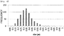
- an average of the maximum diameters of the cells may be greater than or equal to 0.25 ⁇ m and less than or equal to 0.4 ⁇ m.
- a standard deviation of the maximum diameters of the cells may be greater than or equal to 0.05 ⁇ m and less than or equal to 0.2 ⁇ m.
- FIG. 5 shows measurement results of the maximum diameters of the surface cells of the polymer electrolyte membrane according to one embodiment of the present specification. Specifically, FIG. 5 shows a maximum diameter of each cell located on the surface of the polymer electrolyte membrane according to one embodiment of the present specification, and shows a frequency of the maximum diameter of each cell after measuring the maximum diameters. Accordingly, it can be seen that the polymer electrolyte membrane according to one embodiment of the present specification includes cells having uniform sizes.
- the cells may be laminated in two or more layers in any one direction (x-axis direction), a direction vertical thereto (y-axis direction), and a thickness direction of the polymer electrolyte membrane (z-axis direction) on any surface horizontal to the upper surface of the polymer electrolyte membrane.
- the support may have a sponge structure in which two or more of the cells are distributed.
- sections of two or more of the cells may be included in both the vertical section and the horizontal section of the polymer electrolyte membrane.
- the diameter of the cell section of the present specification may mean the length of the longest line crossing the cell section.
- the cell section on the horizontal surface of the polymer electrolyte membrane may have a height to width ratio of 1:1 to 5:1.
- the cell section on the vertical surface of the polymer electrolyte membrane may have a height to width ratio of 1:1 to 10:1.
- the diameter size of the cell section on the horizontal surface of the polymer electrolyte membrane may be greater than or equal to 40 nm and less than or equal to 1,000 nm.
- the diameter size of the cell section on the vertical surface of the polymer electrolyte membrane may be greater than or equal to 40 nm and less than or equal to 1,000 nm.
- the ratio of the cell numbers per 100 ⁇ m 2 of the horizontal surface and the vertical surface of the polymer electrolyte membrane may be from 1:1 to 1:5.
- a variation in the cell numbers on the vertical section and the horizontal section per 100 ⁇ m 2 of the polymer electrolyte membrane may be greater than or equal to 0 and less than or equal to 500.
- an average size of the diameters of the cell sections may be greater than or equal to 40 nm and less than or equal to 500 nm.
- a standard deviation of the diameters of the cell sections may be from 50 nm to 200 nm.
- the cell diameters may be greater than or equal to 40 nm and less than or equal to 1000 nm.
- the support is formed with two or more nodes, and each node may include three or more branches.
- a distance between any one node and another adjacent node of the support may be from 10 nm to 500 nm.
- a length from the center of the cell to any point of the support may be from 20 nm to 500 nm.
- the mixed layer may include greater than or equal to 10 and less than or equal to 400 cells in any region of 1 ⁇ m 3 .
- the mixed layer may include greater than or equal to 10 and less than or equal to 150 cells in any region of 1 ⁇ m 3 ,
- the mixed layer may include greater than or equal to 40 and less than or equal to 150 cells in any region of 1 ⁇ m 3 .
- the ion migration region may be greater than or equal to 40% by volume and less than or equal to 85% by volume with respect to the total volume of the mixed layer.
- the ion migration region may be greater than or equal to 40% by volume and less than or equal to 80% by volume with respect to the total volume of the mixed layer.
- the ion migration region may be greater than or equal to 40% by volume and less than or equal to 70% by volume with respect to the total volume of the mixed layer.
- the ion migration region may be greater than or equal to 40% by volume and less than or equal to 60% by volume with respect to the total volume of the mixed layer.
- the ion migration region may be greater than or equal to 40% by volume and less than or equal to 55% by volume with respect to the total volume of the mixed layer.
- the ion migration region may be greater than or equal to 45% by volume and less than or equal to 65% by volume with respect to the total volume of the mixed layer.
- the ion migration region may be greater than or equal to 45% by volume and less than or equal to 60% by volume with respect to the total volume of the mixed layer.
- the ion migration region in the present specification may mean a region excluding a skeleton formed by the support.
- the ion migration region may be a pore region when only the support is present.
- ions may migrate through the ion-conducting material by the ion-conducting material being included in the ion migration region.
- the ion migration region of the polymer electrolyte membrane according to the present specification is greater than or equal to 40% by volume and less than or equal to 85% by volume, sufficient ion conductance may be secured while securing durability of the polymer electrolyte membrane.
- the ion migration region is less than 40% by volume, durability of the polymer electrolyte membrane is enhanced, however, there is a disadvantage in that sufficient ion conductance is difficult to be secured.
- the ion migration region is greater than 85% by volume, ion conductance of the polymer electrolyte membrane increases, however, there is a disadvantage in that durability is difficult to be secured.
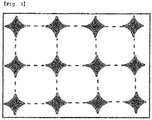
- FIGs. 1 and 2 are diagrams showing one region of the surface of a polymer electrolyte membrane according to one embodiment of the present specification. Specifically, FIG. 1 is a diagram showing one region of the horizontal surface of a polymer electrolyte membrane of the present specification, and FIG. 2 is a diagram showing one region of the vertical surface of a polymer electrolyte membrane of the present specification. Furthermore, the region expressed as a dark region means a support, and a light region means an ion migration region.
- the vertical surface may mean a surface in the thickness direction of the polymer electrolyte membrane.
- the horizontal surface is a surface vertical to the thickness direction of the polymer electrolyte membrane, and may mean a surface occupying a relatively large region.
- the ion migration region may mean a cell section, and cells 3 dimensionally bordering the shown cells are present inside the polymer electrolyte membrane.
- the cell of the present specification may have a spherical shape, a shape of pressed sphere, or a polyhedron shape, and when the cell has a spherical shape, the cell section may have a closed figure having a height to width ratio of 1:1 to 5:1.
- nodes and fibrous branches connecting the nodes of the support may mean a virtual 3-dimensional closed space surrounded by virtual planes formed.
- the node may mean a site in which two or more fibrous branches meet.
- the node may mean a site in which two or more fibrous branches meet to form a branching point including 3 or more branches.
- FIG. 3 is a diagram showing one region of the section of a polymer electrolyte membrane according to one embodiment of the present specification. Specifically, the dotted region in FIG. 3 is a virtual line, and is to divide a virtual 3-dimensional closed space. Those expressed as a dark region are fibrous branches or nodes of a support, and these are connected 3 dimensionally.
- the cell of the present specification is a unit space of an ion migration region including an ion-conducting material surrounded by fibrous branches of the support, and the horizontal and the vertical direction sections of the virtual 3-dimensional closed space in the case of being surrounded by the support fibers may have a figure of a circle, an ellipse or a simple closed curve.
- the cell of the present specification means having a volume of larger than certain sizes, and cells having a diameter of less than 40 nm may not be considered as the cell.
- the diameter of the cell in the present specification may mean a length of the longest line crossing the cell.
- the polymer electrolyte membrane may have an RH cycle limit of at least 20,000 cycles.
- the polymer electrolyte membrane may have an RH cycle limit of at least 40,000 cycles.
- the polymer electrolyte membrane may have an RH cycle limit of at least 50,000 cycles.
- the polymer electrolyte membrane may have an RH cycle limit of at least 60,000 cycles.
- the polymer electrolyte membrane may have an RH cycle limit of at least 70,000 cycles.
- the polymer electrolyte membrane may have an RH cycle limit of at least 75,000 cycles.
- the polymer electrolyte membrane may have an RH cycle limit of at least 80,000 cycles.
- the polymer electrolyte membrane may have an RH cycle limit of at least 100,000 cycles.
- the polymer electrolyte membrane may have an RH cycle limit of at least 120,000 cycles.
- the polymer electrolyte membrane may have an RH cycle limit of at least 150,000 cycles.
- the polymer electrolyte membrane hardly experiences performance decline in the above-mentioned RH cycle range.
- the polymer electrolyte membrane may have an RH cycle limit of 300,000 cycles or less.
- the polymer electrolyte membrane may have an RH cycle limit of 500,000 cycles or less.
- the polymer electrolyte membrane according to one embodiment of the present specification has an advantage of having excellent durability. Specifically, excellent durability of the polymer electrolyte membrane may be identified through an RH cycle. More specifically, the polymer electrolyte membrane according to one embodiment of the present specification has an advantage in that durability decline caused by volume changes that occur while conducting an RH cycle similar to a fuel cell driving condition is significantly small.
- the RH cycle of the present specification means measuring durability in a fuel cell state after preparing the polymer electrolyte membrane as a membrane electrode assembly (MEA).
- the RH cycle in the present specification means measuring durability under a condition of 80°C while injecting nitrogen to an anode at a flow rate of 0.95 slm (standard liter per minute), injecting nitrogen to a cathode at a flow rate of 1.0 slm, and switching between humidification of RH (relative humidity) 150% and non-humidification of RH 0% at an interval of two minutes.
- the RH cycle of the present specification being higher means a polymer electrolyte membrane having higher durability.
- the RH cycle limit means the number of cycles up to the cycle at which a polymer electrolyte membrane is damaged enough to be unusable as an MEA from conducting the RH cycle.
- LSV linear sweep volta-mmetry
- the LSV means measuring hydrogen crossover at 0.1 to 0.4 V (2 mV/s) while injecting hydrogen to an anode at a flow rate of 0.2 slm, and injecting nitrogen to a cathode at a flow rate of 0.2 slm.
- the hydrogen crossover value increases during the RH cycle, a polymer electrolyte membrane may be considered to be damaged, and depending on the degree of the hydrogen crossover value increase, the degree of the polymer electrolyte membrane damage may be determined.
- the polymer electrolyte membrane is damaged enough not to perform its role, and the number of the RH cycles at the time may be the RH cycle limit.
- the RH cycle limit means the number of RH cycles during which the hydrogen crossover value of a polymer electrolyte membrane capable of normal operation increases by 5 or more times.
- the RH cycle having a higher limit means a polymer electrolyte membrane having higher durability, and when the RH cycle limit is at least 20,000 cycles, a polymer electrolyte membrane is generally considered to have excellent durability.
- the polymer electrolyte membrane according to one embodiment of the present specification is capable of maintaining steady performance with almost no performance decline even when the RH cycle limit is 20,000 cycles or greater.
- a maximum stress in the machine direction (MD) of the polymer electrolyte membrane may be 196.133 bar (200 kgf/cm 2 ) or greater.
- a maximum stress in the vertical direction of the machine direction (MD) of the polymer electrolyte membrane may be 196.133 bar (200 kgf/cm 2 ) or greater.
- One embodiment of the present specification provides a polymer electrolyte membrane including a mixed layer that includes an ion migration region and a support having a 3-dimensional network structure, wherein the ion migration region has a structure in which two or more cells including a hydrocarbon-based or partial-hydrocarbon-based ion-conducting material border 3 dimensionally, and a maximum stress in the machine direction (MD) of the polymer electrolyte membrane is 196.133 bar (200 kgf/cm2) or greater.
- MD machine direction
- One embodiment of the present specification provides a polymer electrolyte membrane including a mixed layer that includes an ion migration region and a support having a 3-dimensional network structure, wherein the ion migration region has a structure in which two or more cells including a hydrocarbon-based or partial-hydrocarbon-based ion-conducting material border 3 dimensionally, and a maximum stress in the vertical direction of the machine direction (MD) of the polymer electrolyte membrane is 196.133 bar (200 kgf/cm2) or greater.
- MD machine direction
- the polymer electrolyte membrane may have directivity.
- the support may be prepared through monoaxial orientation or biaxial orientation of a polymer, and the support directivity caused by the orientation may determine the directivity of the polymer electrolyte membrane.
- the polymer electrolyte membrane according to one embodiment of the present specification may have directivity of the machine direction (MD), and directivity of the vertical direction of the machine direction (MD), and the polymer electrolyte membrane may exhibit differences in physical properties such as stress and elongation depending on the directivity.
- the machine direction may have a meaning generally used in the art. Specifically, the machine direction may mean a winding direction when prepared by being wound in a roll form.
- a maximum stress in the machine direction (MD) of the polymer electrolyte membrane may be 294.199 bar (300 kgf/cm2) or greater.
- a maximum stress in the machine direction (MD) of the polymer electrolyte membrane may be 490.332 bar (500 kgf/cm2) or greater.
- a maximum stress in the machine direction (MD) of the polymer electrolyte membrane may be 784.532 bar (800 kgf/cm2) or greater.
- a maximum stress in the machine direction (MD) of the polymer electrolyte membrane may be 882.598 bar (900 kgf/cm2) or greater.
- a maximum stress in the vertical direction of the machine direction (MD) of the polymer electrolyte membrane may be 294.199 bar (300 kgf/cm2) or greater.
- a maximum stress in the vertical direction of the machine direction (MD) of the polymer electrolyte membrane may be 392.266 bar (400 kgf/cm2) or greater.
- a maximum stress in the vertical direction of the machine direction (MD) of the polymer electrolyte membrane may be 588.399 bar(600 kgf/cm2) or greater.
- a maximum stress in the vertical direction of the machine direction (MD) of the polymer electrolyte membrane may be 784.532 bar(800 kgf/cm2) or greater.
- a maximum elongation in the machine direction (MD) of the polymer electrolyte membrane may be 20% or greater.
- a maximum elongation in the machine direction (MD) of the polymer electrolyte membrane may be 50% or greater.
- a maximum elongation in the machine direction (MD) of the polymer electrolyte membrane may be 60% or greater.
- a maximum elongation in the vertical direction of the machine direction (MD) of the polymer electrolyte membrane may be 10% or greater.
- a maximum elongation in the vertical direction of the machine direction (MD) of the polymer electrolyte membrane may be 30% or greater.
- the maximum stress in the present specification means a magnitude of force per unit area in the instant of a polymer electrolyte membrane cut with a distance between grips of 100 mm and a tension speed of 10 mm/min under a condition of a temperature of 20°C and humidity of 22%.
- the maximum elongation in the present specification means a percentage of polymer electrolyte membrane stretching in the instant of the polymer electrolyte membrane cut with a distance between grips of 100 mm and a tension speed of 10 mm/min under a condition of a temperature of 20°C and humidity of 22%.
- the maximum stress and the maximum elongation in the present specification means measuring a polymer electrolyte membrane cut in the form of a dog bone according to the American Society for Testing and Materials (ASTM) standard at a speed of 10 mm/min using a united test machine (UTM) .
- the UTM is an apparatus simultaneously measuring tensile strength and elongation, and is an apparatus generally used in the art.
- the polymer electrolyte according to one embodiment of the present specification has a high maximum stress, therefore, has an advantage of performing its function for a long period of time without performance variations in a fuel cell in which an electrolyte membrane is repeatedly expanded and contracted due to the repetition of high temperature humidification and drying.
- the ion migration region may include the ion-conducting material in greater than or equal to 60% by volume and less than or equal to 100% by volume.
- the ion migration region may include the ion-conducting material in greater than or equal to 70% by volume and less than or equal to 100% by volume.
- the polymer electrolyte membrane may have air permeability of 1 hour/100 ml or greater.
- the polymer electrolyte membrane according to one embodiment of the present specification may exhibit excellent efficiency in a fuel cell by forming a dense structure. Specifically, the dense structure of the polymer electrolyte membrane may be shown through the air permeability value. When the polymer electrolyte membrane according to one embodiment of the present specification has air permeability in the above-mentioned range, excellent electrolyte membrane performance may be exhibited in a fuel cell.
- the present specification provides a membrane electrode assembly including the polymer electrolyte membrane.
- the present specification provides a fuel cell including the membrane electrode assembly.
- the fuel cell of the present specification includes fuel cells generally known in the art.
- One embodiment of the present specification provides a fuel cell including a stack that includes the membrane electrode assembly and a separator provided between the membrane electrode assemblies; a fuel supply unit supplying fuel to the stack; and an oxidizer supply unit supplying an oxidizer to the stack.
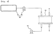
- FIG. 4 is a diagram showing the structure of a fuel cell according to one embodiment of the present specification, and the fuel cell is formed including a stack (60), an oxidizer supply unit (70) and a fuel supply unit (80).
- the stack (200) includes one, two or more of the membrane electrode assemblies, and when two or more of the membrane electrode assemblies are included, a separator provided therebetween is included.
- the separator prevents the membrane electrode assemblies from being electrically connected, and performs a role of transferring a fuel and an oxidizer supplied from the outside.
- the oxidizer supply unit (70) performs a role of supplying an oxidizer to the stack (60).
- oxygen is typically used, and oxygen or air may be used by being injected with a pump (70).
- the fuel supply unit (80) performs a role of supplying a fuel to the stack (60), and may be formed with a fuel tank (81) storing a fuel, and a pump (82) supplying the fuel stored in the fuel tank (81) to the stack (60).
- a fuel tank (81) storing a fuel
- a pump (82) supplying the fuel stored in the fuel tank (81) to the stack (60).
- the fuel a hydrogen or hydrocarbon fuel in a gas or liquid state may be used, and examples of the hydrocarbon fuel may include methanol, ethanol, propanol, butanol or natural gas.
- an immersion solution was made by dissolving a sulfonated polyether-etherketone-based polymer in dimethyl sulfoxide (DMSO) to have a concentration of 7 wt%, and then a support having porosity of approximately 70% and a thickness of approximately 15 ⁇ m fixed on a frame of 10 cm ⁇ 10 cm was immersed into the immersion solution. After that, the result was dried for 24 hours in an oven at 80°C, and a polymer electrolyte membrane was prepared. The prepared membrane was acid treated for 24 hours in 10% sulfuric acid at 80°C, washed 4 or more times with distilled water, dried, and then used.
- DMSO dimethyl sulfoxide
- the final thickness of the polymer electrolyte membrane prepared according to Example 1 was from 11 ⁇ m to 12 ⁇ m, the thickness of a mixed layer was from 7 ⁇ m to 8 ⁇ m, the thickness of a pure layer provided on the upper part of the mixed layer was from 0.7 ⁇ m to 1.2 ⁇ m, and the thickness of a pure layer provided on the lower part of the mixed layer was from 2 ⁇ m to 3 ⁇ m.
- a polymer electrolyte membrane was prepared by casting only the immersion solution used in Example 1 on a glass plate to a thickness of 400 ⁇ m, and then drying the result for 24 hours in an oven at 80°C.
- the prepared polymer electrolyte membrane was treated in the same manner as in Example 1, and then used.
- the polymer electrolyte membrane prepared according to Comparative Example 1 was formed only with a pure layer, and the thickness was 20 ⁇ m.
- an immersion solution was made by dissolving a sulfonated polyether-etherketone-based polymer in dimethyl sulfoxide (DMSO) to have a concentration of 7 wt%, and then a support having porosity of approximately 65% and a thickness of approximately 20 ⁇ m fixed on a frame of 10 cmxl0 cm was immersed into the immersion solution. After that, approximately 5 ml of the immersion solution was additionally coated on one surface of the immersed support, then the result was dried for 24 hours in an oven at 80°C, and a polymer electrolyte membrane was prepared.
- DMSO dimethyl sulfoxide
- the prepared membrane was acid treated for 24 hours in 10% sulfuric acid at 80°C, washed 4 or more times with distilled water, dried, and then used.
- the final thickness of the polymer electrolyte membrane prepared according to Comparative Example 1 was approximately from 56 ⁇ m to 62 ⁇ m, the thickness of a mixed layer was from 13 ⁇ m to 14 ⁇ m, the thickness of a pure layer of the surface on which the immersion solution was additionally coated was from 30 ⁇ m to 33 ⁇ m, and the thickness of a pure layer of the surface opposite thereto was from 13 ⁇ m to 15 ⁇ m.
- an immersion solution was made by dissolving a sulfonated polyether-etherketone-based polymer in DMSO to have a concentration of 7 wt%, and then a support having porosity of approximately 70% and a thickness of approximately 3 ⁇ m fixed on a frame of 10 cmxl0 cm was immersed into the immersion solution. After that, the result was dried for 24 hours in an oven at 80°C, and a polymer electrolyte membrane was prepared. The prepared membrane was acid treated for 24 hours in 10% sulfuric acid at 80°C, washed 4 or more times with distilled water, dried, and then used.
- the final thickness of the polymer electrolyte membrane prepared according to Comparative Example 1 was approximately from 6.3 ⁇ m to 6.6 ⁇ m, the thickness of a mixed layer was from 1.6 ⁇ m to 1.8 ⁇ m, the thickness of a pure layer provided on the upper part of the mixed layer was from 2.3 ⁇ m to 2.5 ⁇ m, and the thickness of a pure layer provided on the lower part of the mixed layer was from 2.1 ⁇ m to 2.3 ⁇ m.
- the x axis means the number of an RH cycle
- the y axis relates to a hydrogen crossover value allowing the estimation of the degree of polymer electrolyte membrane damage while the RH cycle is progressed.
Description
- The present specification claims priority to and the benefits of Korean Patent Application No.
10-2013-0047773 10-2013-0049424 10-2013-0132160 10-2013-0144440 - The present specification provides a polymer electrolyte membrane, a membrane electrode assembly including the polymer electrolyte membrane, and a fuel cell including the membrane electrode assembly.
- A fuel cell is a high efficiency power generating device, and has advantages in that the amount of fuel use is low due to high efficiency compared to existing internal combustion engines, and it is a pollution-free energy source that does not produce environmental pollutants such as SOx, NOx, VOC and the like. In addition, there are additional advantages in that a locational area required for production facilities is small, and a construction period is short.
- Accordingly, a fuel cell has a variety of applications covering a mobile power supply such as portable devices, a transport power supply such as vehicles, and dispersion power generation usable for domestic use and electric power industries. Particularly, when an operation of a fuel cell vehicle, a next generation transportation device, is commercialized, the potential market size is expected to be extensive.
- A fuel cell is largely divided into 5 types depending on the operating temperature and the electrolyte, which specifically includes an alkali fuel cell (AFC), a phosphoric acid fuel cell (PAFC), a molten carbonate fuel cell (MCFC), a solid oxide fuel cell (SOFC), a polymer electrolyte membrane fuel cell (PEMFC) and a direct methanol fuel cell (DMFC) . Among these, a polymer electrolyte membrane fuel cell and a direct methanol fuel cell having excellent mobility have received wide attention as a future power supply.
- A polymer electrolyte membrane fuel cell has a basic principle such that gas diffusing electrode layers are disposed on both surfaces of a polymer electrolyte membrane, and water is produced by a chemical reaction through the polymer electrolyte membrane by facing an anode toward a fuel electrode and a cathode toward an oxidation electrode, and the reaction energy produced therefrom is converted to electric energy.
- A typical example of an ion-conducting polymer electrolyte membrane may include Nafion, a perfluorinated hydrogen ion exchange membrane developed by Dupont USA in early 1960s. Similar commercialized perfluorinated polymer electrolyte membranes other than Nafion include Aciplex-S membrane manufactured by Asahi Kasei Chemicals Corporation, Dow membrane manufactured by Dow Chemical Company, Flemion membrane manufactured by Asahi Glass Co., Ltd., and the like.
- Existing commercialized perfluorinated polymer electrolyte membrane has chemical resistance, oxidation resistance, and excellent ion conductance, but has a problem of being expensive and causing environmental problems due to the toxicity of intermediates produced during manufacture. Accordingly, polymer electrolyte membranes in which a carboxyl group, a sulfonic acid group or the like is introduced to an aromatic ring polymer have been studied in order to compensate for the weaknesses of such perfluorinated polymer electrolyte membranes. Examples thereof include sulfonated polyarylether sulfone [Journal of Membrane Science, 1993, 83, 211], sulfonated polyetherether ketone [Japanese Patent Application Laid-Open Publication No.
H06-93114 US Patent No. 5,438,082 ], sulfonated polyimide [US Patent No. 6,245,881 ] and the like. - A polymer electrolyte membrane accompanies changes in membrane thicknesses and volumes of 15 to 30% depending on the temperature and the degree of hydration, and accordingly, the electrolyte membrane is repeatedly expanded and contracted depending on the operation condition of a fuel cell, and microholes or cracks occur due to such volume changes. In addition, as a side reaction, hydrogen peroxide (H2O2) or peroxide radicals are generated from a reduction reaction of oxygen in a cathode, which may cause the degradation of the electrolyte membrane. A polymer electrolyte membrane for a fuel cell has been developed in the direction of improving mechanical and chemical durability keeping such a phenomenon that may occur during the fuel cell driving in mind.
- Studies that have been carried out for improving mechanical durability include a reinforcing composite electrolyte membrane prepared by introducing a Nafion solution (5% by weight concentration) to an e-PTFE (
US Patent No. 5,547,551 ), and a polymer blend composite membrane introducing a polymer having excellent dimensional stability to a sulfonated hydrocarbon-based polymer material (Korean Patent No.10-0746339 - In a reinforcing composite electrolyte membrane, a porous support is used in order to provide mechanical properties and dimensional stability. A porous support needs to maintain mechanical durability while not declining the performances, therefore, a support made of suitable materials provided with high porosity and excellent mechanical properties needs to be selected. In addition, ion conductivity of a membrane greatly varies depending on the method of immersing an ion conductor into a support and the type of the ion conductor, therefore, development of an effective method of immersing an ion conductor, and an ion conductor suitable for a reinforcing composite electrolyte membrane has been required.
- An object of the present specification is to provide a polymer electrolyte membrane, and moreover, to provide a membrane electrode assembly including the polymer electrolyte membrane, and a fuel cell including the membrane electrode assembly.
- One embodiment of the present specification provides a polymer electrolyte membrane as disclosed in
claim 1. One embodiment of the present specification provides a membrane electrode assembly including the polymer electrolyte membrane. - One embodiment of the present specification provides a fuel cell including the membrane electrode assembly.
- A polymer electrolyte membrane according to one embodiment of the present specification has an advantage of having excellent durability. Specifically, using a membrane electrode assembly including the polymer electrolyte membrane according to one embodiment of the present specification in a fuel cell may contribute to performance enhancement of the fuel cell. In other words, a polymer electrolyte membrane according to one embodiment of the present specification minimizes performance decline of a fuel cell in the working environment of the fuel cell in which high temperature humidification and drying are repeated leading to the repetition of contraction and expansion of a polymer electrolyte membrane, and allows the fuel cell to maintain steady performance.
-
-
FIGs. 1 and2 are diagrams showing one region of a surface of a polymer electrolyte membrane according to one embodiment of the present specification. -
FIG. 3 is a diagram showing one region of a section of a polymer electrolyte membrane according to one embodiment of the present specification. -
FIG. 4 is a diagram showing a structure of a fuel cell according to one embodiment of the present specification. -
FIG. 5 shows measurement results of maximum diameters of the surface cells of a polymer electrolyte membrane according to one embodiment of the present specification. -
FIG. 6 shows RH cycle results according to examples and comparative examples. - Hereinafter, the present specification will be described in more detail.
- In the present specification, a description of one member being placed "on" another member includes not only a case of the one member adjoining the another member but a case of still another member being present between the two members.
- In the present specification, a description of a certain part "including" certain constituents means capable of further including other constituents, and does not exclude other constituents unless particularly stated on the contrary.
- One embodiment of the present specification provides a polymer electrolyte membrane including a mixed layer that includes an ion migration region and a support having a 3-dimensional network structure, wherein the ion migration region has a structure in which two or more cells including an ion-conducting
material border 3 dimensionally, and the thickness ratio of the mixed layer is greater than or equal to 30% and less than or equal to 100% with respect to the total thickness of the polymer electrolyte membrane. - According to one embodiment of the present specification, the thickness ratio of the mixed layer with respect to the total thickness of the polymer electrolyte membrane may be greater than or equal to 50% and less than or equal to 100%.
- According to one embodiment of the present specification, the thickness ratio of the mixed layer with respect to the total thickness of the polymer electrolyte membrane may be greater than or equal to 65% and less than or equal to 95%.
- When the thickness ratio of the mixed layer with respect to the total thickness of the polymer electrolyte membrane is outside the above-mentioned range and less than 50% with respect to the total thickness of the polymer electrolyte membrane, a durability enhancing effect of the mixed layer by the support may be insignificant. Specifically, when the thickness of the mixed layer is less than 50% with respect to the total thickness of the polymer electrolyte membrane, the polymer electrolyte membrane may have reduced durability due to an influence of the behavior of a pure layer formed with an ion-conducting material.
- According to one embodiment of the present specification, the polymer electrolyte membrane may be formed only with the mixed layer. Specifically, according to one embodiment of the present specification, when the polymer electrolyte membrane is formed only with the mixed layer, the thickness ratio of the mixed layer with respect to the total thickness of the polymer electrolyte membrane may be 100%.
- According to one embodiment of the present specification, the thickness ratio of the mixed layer with respect to the total thickness of the polymer electrolyte membrane may be greater than or equal to 50% and less than 100%. Specifically, according to one embodiment of the present specification, the polymer electrolyte membrane may further include a pure layer formed with the ion-conducting material on the upper surface and/or the lower surface of the mixed layer.
- When the polymer electrolyte membrane is formed only with the mixed layer, joint strength between the polymer electrolyte membrane and an electrode may be reduced, and this may lead to a problem of the electrode and the polymer electrolyte membrane being separated while operating a fuel cell.
- One embodiment of the present specification provides a polymer electrolyte membrane in which the mixed layer has a thickness of greater than or equal to 1 µm and less than or equal to 30 µm.
- According to one embodiment of the present specification, the thickness of the mixed layer may be greater than or equal to 1 µm and less than or equal to 25 µm.
- According to one embodiment of the present specification, the thickness of the mixed layer may be greater than or equal to 1 µm and less than or equal to 15 µm.
- According to one embodiment of the present specification, the thickness of the mixed layer may be greater than or equal to 5 µm and less than or equal to 15 µm.
- When the thickness of the mixed layer according to the present specification is greater than or equal to 1 µm and less than or equal to 30 µm, high ion conductance and durability may be obtained. In addition, when the thickness of the mixed layer is within the above-mentioned range, durability decline due to a thickness decrease may hardly occur. In other words, when the thickness of the mixed layer is less than 1 µm, there is a disadvantage in that durability is not maintained, and when the thickness is greater than 30 µm, there is a disadvantage in that ion conductance may decrease.
- According to one embodiment of the present specification, the polymer electrolyte membrane may further include a pure layer including only the ion-conducting material provided on the upper surface, the lower surface, or the upper surface and the lower surface of the mixed layer.
- According to one embodiment of the present specification, the mixed layer may be formed by immersing the support into the ion-conducting material.
- Specifically, according to one embodiment of the present specification, when the ion-conducting material is included up to the thickness range of the support, a polymer electrolyte membrane without a pure layer may be formed. In addition, according to one embodiment of the present specification, when the ion-conducting material is included exceeding the thickness range of the support, a polymer electrolyte membrane provided with a pure layer on the upper surface and/or the lower surface of the mixed layer may be prepared.
- According to one embodiment of the present specification, an ion-conducting material included in the mixed layer and an ion-conducting material included in the pure layer may be different from each other. Specifically, according to one embodiment of the present specification, after forming the mixed layer, a pure layer may be formed by coating an ion-conducting material that is different from an ion-conducting material included in the mixed layer on the upper surface and/or the lower surface of the mixed layer.
- According to one embodiment of the present specification, the pure layers provided on any one surface of the mixed layer may be each independently laminated in two or more layers, and each layer may include a different ion-conducting material.
- According to one embodiment of the present specification, the thicknesses of the pure layers provided on any one surface of the mixed layer may be each independently greater than 0 µm and less than or equal to 6 µm.
- According to one embodiment of the present specification, the pure layers may be each provided on the upper surface and the lower surface of the mixed layer.
- According to one embodiment of the present specification, the thickness difference between the pure layers each provided on the upper surface and the lower surface of the mixed layer may be 50% or less of the thickness of the mixed layer. Specifically, the thickness difference between the pure layers provided on the upper surface and the lower surface of the mixed layer may be 30% or less of the thickness of the mixed layer. According to one embodiment of the present specification, the thickness difference between the pure layers being 0% of the thickness of the mixed layer means that the thicknesses of the pure layers each provided on the upper surface and the lower surface of the mixed layer are the same.
- According to one embodiment of the present specification, when the thickness difference between the pure layer provided on the lower surface of the mixed layer and the pure layer provided on the upper surface of the mixed layer is 50% or less of the thickness of the mixed layer, the degree of contraction and expansion of the upper surface and the lower surface of the polymer electrolyte membrane becomes similar even when humidification and drying of the polymer electrolyte membrane are repeated, and the occurrence of cracks may be prevented.
- According to one embodiment of the present specification, the thickness ratio of the mixed layer and the whole pure layer may be from 1:0 to 1:4. Specifically, the thickness ratio of the mixed layer and the whole pure layer may be from 1:0 to 1:1.5. More specifically, the thickness ratio of the mixed layer and the whole pure layer may be from 1:0 to 1:1.
- The polymer electrolyte membrane according to one embodiment of the present specification is capable of exhibiting high durability under a condition that humidified and dried states are repeated as the thickness ratio of the mixed layer increases with respect to the pure layer.
- According to one embodiment of the present specification, the total thickness of the polymer electrolyte membrane may be greater than or equal to 3 µm and less than or equal to 36 µm.
- According to one embodiment of the present specification, the ion-conducting material includes sulfonated polyether-etherketone-based polymer.
- According to one embodiment of the present specification, the ion-conducting material may have ion conductance of 1 mS/cm or greater at 60°C or higher.
- According to one embodiment of the present specification, the ion-conducting material may have ion exchange capacity (IEC) of 1 meq/g or greater.
- According to one embodiment of the present specification, the support includes polyolefin, polyamide, polyester, polyacetal (or polyoxymethylene), polysulfide, polyvinyl alcohol, copolymers thereof and combinations thereof, but is not limited thereto.
- The polyolefin may include polyethylene (LDPE, LLDPE, HDPE, UHMWPE), polypropylene, polybutene, polymethylpentene, copolymers thereof and blends thereof.
- The polyamide may include polyamide 6, polyamide 6/6,
nylon 10/10, polyphthalamide (PPA), copolymers thereof and blends thereof, but is not limited thereto. - The polyester may include polyester terephthalate (PET), polybutylene terephthalate (PBT), poly-1-4-cyclohexylenedimethylene terephthalate (PCT), polyethylene naphthalate (PEN) and liquid crystal polymers (LCP), but is not limited thereto.
- The polysulfide includes polyphenyl sulfide, polyethylene sulfide, copolymers thereof and blends thereof, but is not limited thereto.
- The polyvinyl alcohol includes ethylene-vinyl alcohol, copolymers thereof and blends thereof, but is not limited thereto.
- The polymer electrolyte membrane according to one embodiment of the present specification may include cells having uniform sizes.
- Specifically, according to one embodiment of the present specification, an average of the maximum diameters of the cells may be greater than or equal to 0.25 µm and less than or equal to 0.4 µm. In addition, according to one embodiment of the present specification, a standard deviation of the maximum diameters of the cells may be greater than or equal to 0.05 µm and less than or equal to 0.2 µm.
-
FIG. 5 shows measurement results of the maximum diameters of the surface cells of the polymer electrolyte membrane according to one embodiment of the present specification. Specifically,FIG. 5 shows a maximum diameter of each cell located on the surface of the polymer electrolyte membrane according to one embodiment of the present specification, and shows a frequency of the maximum diameter of each cell after measuring the maximum diameters. Accordingly, it can be seen that the polymer electrolyte membrane according to one embodiment of the present specification includes cells having uniform sizes. - According to one embodiment of the present specification, the cells may be laminated in two or more layers in any one direction (x-axis direction), a direction vertical thereto (y-axis direction), and a thickness direction of the polymer electrolyte membrane (z-axis direction) on any surface horizontal to the upper surface of the polymer electrolyte membrane.
- According to one embodiment of the present specification, the support may have a sponge structure in which two or more of the cells are distributed.
- According to one embodiment of the present specification, sections of two or more of the cells may be included in both the vertical section and the horizontal section of the polymer electrolyte membrane.
- The diameter of the cell section of the present specification may mean the length of the longest line crossing the cell section.
- According to one embodiment of the present specification, the cell section on the horizontal surface of the polymer electrolyte membrane may have a height to width ratio of 1:1 to 5:1.
- According to one embodiment of the present specification, the cell section on the vertical surface of the polymer electrolyte membrane may have a height to width ratio of 1:1 to 10:1.
- According to one embodiment of the present specification, the diameter size of the cell section on the horizontal surface of the polymer electrolyte membrane may be greater than or equal to 40 nm and less than or equal to 1,000 nm.
- According to one embodiment of the present specification, the diameter size of the cell section on the vertical surface of the polymer electrolyte membrane may be greater than or equal to 40 nm and less than or equal to 1,000 nm.
- According to one embodiment of the present specification, the ratio of the cell numbers per 100 µm2 of the horizontal surface and the vertical surface of the polymer electrolyte membrane may be from 1:1 to 1:5.
- According to one embodiment of the present specification, a variation in the cell numbers on the vertical section and the horizontal section per 100 µm2 of the polymer electrolyte membrane may be greater than or equal to 0 and less than or equal to 500.
- According to one embodiment of the present specification, an average size of the diameters of the cell sections may be greater than or equal to 40 nm and less than or equal to 500 nm.
- According to one embodiment of the present specification, a standard deviation of the diameters of the cell sections may be from 50 nm to 200 nm.
- According to one embodiment of the present specification, the cell diameters may be greater than or equal to 40 nm and less than or equal to 1000 nm.
- According to one embodiment of the present specification, the support is formed with two or more nodes, and each node may include three or more branches.
- According to one embodiment of the present specification, a distance between any one node and another adjacent node of the support may be from 10 nm to 500 nm.
- According to one embodiment of the present specification, a length from the center of the cell to any point of the support may be from 20 nm to 500 nm.
- According to one embodiment of the present specification, the mixed layer may include greater than or equal to 10 and less than or equal to 400 cells in any region of 1 µm3.
- According to one embodiment of the present specification, the mixed layer may include greater than or equal to 10 and less than or equal to 150 cells in any region of 1 µm3,
- According to one embodiment of the present specification, the mixed layer may include greater than or equal to 40 and less than or equal to 150 cells in any region of 1 µm3.
- According to one embodiment of the present specification, the ion migration region may be greater than or equal to 40% by volume and less than or equal to 85% by volume with respect to the total volume of the mixed layer.
- According to one embodiment of the present specification, the ion migration region may be greater than or equal to 40% by volume and less than or equal to 80% by volume with respect to the total volume of the mixed layer.
- According to one embodiment of the present specification, the ion migration region may be greater than or equal to 40% by volume and less than or equal to 70% by volume with respect to the total volume of the mixed layer.
- According to one embodiment of the present specification, the ion migration region may be greater than or equal to 40% by volume and less than or equal to 60% by volume with respect to the total volume of the mixed layer.
- According to one embodiment of the present specification, the ion migration region may be greater than or equal to 40% by volume and less than or equal to 55% by volume with respect to the total volume of the mixed layer.
- According to one embodiment of the present specification, the ion migration region may be greater than or equal to 45% by volume and less than or equal to 65% by volume with respect to the total volume of the mixed layer.
- According to one embodiment of the present specification, the ion migration region may be greater than or equal to 45% by volume and less than or equal to 60% by volume with respect to the total volume of the mixed layer.
- The ion migration region in the present specification may mean a region excluding a skeleton formed by the support. In addition, the ion migration region may be a pore region when only the support is present. Moreover, ions may migrate through the ion-conducting material by the ion-conducting material being included in the ion migration region.
- When the ion migration region of the polymer electrolyte membrane according to the present specification is greater than or equal to 40% by volume and less than or equal to 85% by volume, sufficient ion conductance may be secured while securing durability of the polymer electrolyte membrane. In other words, when the ion migration region is less than 40% by volume, durability of the polymer electrolyte membrane is enhanced, however, there is a disadvantage in that sufficient ion conductance is difficult to be secured. Moreover, when the ion migration region is greater than 85% by volume, ion conductance of the polymer electrolyte membrane increases, however, there is a disadvantage in that durability is difficult to be secured.
-
FIGs. 1 and2 are diagrams showing one region of the surface of a polymer electrolyte membrane according to one embodiment of the present specification. Specifically,FIG. 1 is a diagram showing one region of the horizontal surface of a polymer electrolyte membrane of the present specification, andFIG. 2 is a diagram showing one region of the vertical surface of a polymer electrolyte membrane of the present specification. Furthermore, the region expressed as a dark region means a support, and a light region means an ion migration region. - The vertical surface may mean a surface in the thickness direction of the polymer electrolyte membrane. In addition, the horizontal surface is a surface vertical to the thickness direction of the polymer electrolyte membrane, and may mean a surface occupying a relatively large region.
- In
FIG. 1 andFIG. 2 , the ion migration region may mean a cell section, andcells 3 dimensionally bordering the shown cells are present inside the polymer electrolyte membrane. - The cell of the present specification may have a spherical shape, a shape of pressed sphere, or a polyhedron shape, and when the cell has a spherical shape, the cell section may have a closed figure having a height to width ratio of 1:1 to 5:1.
- When nodes and fibrous branches connecting the nodes of the support are connected in the cell of the present specification, it may mean a virtual 3-dimensional closed space surrounded by virtual planes formed. The node may mean a site in which two or more fibrous branches meet. Specifically, the node may mean a site in which two or more fibrous branches meet to form a branching point including 3 or more branches.
-
FIG. 3 is a diagram showing one region of the section of a polymer electrolyte membrane according to one embodiment of the present specification. Specifically, the dotted region inFIG. 3 is a virtual line, and is to divide a virtual 3-dimensional closed space. Those expressed as a dark region are fibrous branches or nodes of a support, and these are connected 3 dimensionally. - In addition, the cell of the present specification is a unit space of an ion migration region including an ion-conducting material surrounded by fibrous branches of the support, and the horizontal and the vertical direction sections of the virtual 3-dimensional closed space in the case of being surrounded by the support fibers may have a figure of a circle, an ellipse or a simple closed curve.
- In addition, the cell of the present specification means having a volume of larger than certain sizes, and cells having a diameter of less than 40 nm may not be considered as the cell.
- The diameter of the cell in the present specification may mean a length of the longest line crossing the cell.
- According to one embodiment of the present specification, the polymer electrolyte membrane may have an RH cycle limit of at least 20,000 cycles.
- According to one embodiment of the present specification, the polymer electrolyte membrane may have an RH cycle limit of at least 40,000 cycles.
- In addition, according to one embodiment of the present specification, the polymer electrolyte membrane may have an RH cycle limit of at least 50,000 cycles.
- Furthermore, according to one embodiment of the present specification, the polymer electrolyte membrane may have an RH cycle limit of at least 60,000 cycles.
- In addition, according to one embodiment of the present specification, the polymer electrolyte membrane may have an RH cycle limit of at least 70,000 cycles.
- Furthermore, according to one embodiment of the present specification, the polymer electrolyte membrane may have an RH cycle limit of at least 75,000 cycles.
- In addition, according to one embodiment of the present specification, the polymer electrolyte membrane may have an RH cycle limit of at least 80,000 cycles.
- Furthermore, according to one embodiment of the present specification, the polymer electrolyte membrane may have an RH cycle limit of at least 100,000 cycles.
- In addition, according to one embodiment of the present specification, the polymer electrolyte membrane may have an RH cycle limit of at least 120,000 cycles.
- Furthermore, according to one embodiment of the present specification, the polymer electrolyte membrane may have an RH cycle limit of at least 150,000 cycles.
- According to one embodiment of the present specification, the polymer electrolyte membrane hardly experiences performance decline in the above-mentioned RH cycle range.
- According to one embodiment of the present specification, the polymer electrolyte membrane may have an RH cycle limit of 300,000 cycles or less.
- According to one embodiment of the present specification, the polymer electrolyte membrane may have an RH cycle limit of 500,000 cycles or less.
- The polymer electrolyte membrane according to one embodiment of the present specification has an advantage of having excellent durability. Specifically, excellent durability of the polymer electrolyte membrane may be identified through an RH cycle. More specifically, the polymer electrolyte membrane according to one embodiment of the present specification has an advantage in that durability decline caused by volume changes that occur while conducting an RH cycle similar to a fuel cell driving condition is significantly small.
- The RH cycle of the present specification means measuring durability in a fuel cell state after preparing the polymer electrolyte membrane as a membrane electrode assembly (MEA). Specifically, the RH cycle in the present specification means measuring durability under a condition of 80°C while injecting nitrogen to an anode at a flow rate of 0.95 slm (standard liter per minute), injecting nitrogen to a cathode at a flow rate of 1.0 slm, and switching between humidification of RH (relative humidity) 150% and non-humidification of
RH 0% at an interval of two minutes. - Moreover, the RH cycle of the present specification being higher means a polymer electrolyte membrane having higher durability. In addition, the RH cycle limit means the number of cycles up to the cycle at which a polymer electrolyte membrane is damaged enough to be unusable as an MEA from conducting the RH cycle.
- In order to measure the RH cycle limit in the present specification, linear sweep volta-mmetry (LSV) is used. Specifically, the LSV means measuring hydrogen crossover at 0.1 to 0.4 V (2 mV/s) while injecting hydrogen to an anode at a flow rate of 0.2 slm, and injecting nitrogen to a cathode at a flow rate of 0.2 slm. In other words, when the hydrogen crossover value increases during the RH cycle, a polymer electrolyte membrane may be considered to be damaged, and depending on the degree of the hydrogen crossover value increase, the degree of the polymer electrolyte membrane damage may be determined. When a hydrogen crossover value rapidly increases during the RH cycle, the polymer electrolyte membrane is damaged enough not to perform its role, and the number of the RH cycles at the time may be the RH cycle limit.
- For example, the RH cycle limit means the number of RH cycles during which the hydrogen crossover value of a polymer electrolyte membrane capable of normal operation increases by 5 or more times.
- In other words, the RH cycle having a higher limit means a polymer electrolyte membrane having higher durability, and when the RH cycle limit is at least 20,000 cycles, a polymer electrolyte membrane is generally considered to have excellent durability. The polymer electrolyte membrane according to one embodiment of the present specification is capable of maintaining steady performance with almost no performance decline even when the RH cycle limit is 20,000 cycles or greater.
- According to one embodiment of the present specification, a maximum stress in the machine direction (MD) of the polymer electrolyte membrane may be 196.133 bar (200 kgf/cm2) or greater.
- According to one embodiment of the present specification, a maximum stress in the vertical direction of the machine direction (MD) of the polymer electrolyte membrane may be 196.133 bar (200 kgf/cm2) or greater.
- One embodiment of the present specification provides a polymer electrolyte membrane including a mixed layer that includes an ion migration region and a support having a 3-dimensional network structure, wherein the ion migration region has a structure in which two or more cells including a hydrocarbon-based or partial-hydrocarbon-based ion-conducting
material border 3 dimensionally, and a maximum stress in the machine direction (MD) of the polymer electrolyte membrane is 196.133 bar (200 kgf/cm2) or greater. - One embodiment of the present specification provides a polymer electrolyte membrane including a mixed layer that includes an ion migration region and a support having a 3-dimensional network structure, wherein the ion migration region has a structure in which two or more cells including a hydrocarbon-based or partial-hydrocarbon-based ion-conducting
material border 3 dimensionally, and a maximum stress in the vertical direction of the machine direction (MD) of the polymer electrolyte membrane is 196.133 bar (200 kgf/cm2) or greater. - According to one embodiment of the present specification, the polymer electrolyte membrane may have directivity. Specifically, according to one embodiment of the present specification, the support may be prepared through monoaxial orientation or biaxial orientation of a polymer, and the support directivity caused by the orientation may determine the directivity of the polymer electrolyte membrane. Accordingly, the polymer electrolyte membrane according to one embodiment of the present specification may have directivity of the machine direction (MD), and directivity of the vertical direction of the machine direction (MD), and the polymer electrolyte membrane may exhibit differences in physical properties such as stress and elongation depending on the directivity.
- The machine direction (MD) may have a meaning generally used in the art. Specifically, the machine direction may mean a winding direction when prepared by being wound in a roll form.
- According to one embodiment of the present specification, a maximum stress in the machine direction (MD) of the polymer electrolyte membrane may be 294.199 bar (300 kgf/cm2) or greater.
- According to one embodiment of the present specification, a maximum stress in the machine direction (MD) of the polymer electrolyte membrane may be 490.332 bar (500 kgf/cm2) or greater.
- According to one embodiment of the present specification, a maximum stress in the machine direction (MD) of the polymer electrolyte membrane may be 784.532 bar (800 kgf/cm2) or greater.
- According to one embodiment of the present specification, a maximum stress in the machine direction (MD) of the polymer electrolyte membrane may be 882.598 bar (900 kgf/cm2) or greater.
- According to one embodiment of the present specification, a maximum stress in the vertical direction of the machine direction (MD) of the polymer electrolyte membrane may be 294.199 bar (300 kgf/cm2) or greater.
- According to one embodiment of the present specification, a maximum stress in the vertical direction of the machine direction (MD) of the polymer electrolyte membrane may be 392.266 bar (400 kgf/cm2) or greater.
- According to one embodiment of the present specification, a maximum stress in the vertical direction of the machine direction (MD) of the polymer electrolyte membrane may be 588.399 bar(600 kgf/cm2) or greater.
- According to one embodiment of the present specification, a maximum stress in the vertical direction of the machine direction (MD) of the polymer electrolyte membrane may be 784.532 bar(800 kgf/cm2) or greater.
- According to one embodiment of the present specification, a maximum elongation in the machine direction (MD) of the polymer electrolyte membrane may be 20% or greater.
- According to one embodiment of the present specification, a maximum elongation in the machine direction (MD) of the polymer electrolyte membrane may be 50% or greater.
- According to one embodiment of the present specification, a maximum elongation in the machine direction (MD) of the polymer electrolyte membrane may be 60% or greater.
- According to one embodiment of the present specification, a maximum elongation in the vertical direction of the machine direction (MD) of the polymer electrolyte membrane may be 10% or greater.
- According to one embodiment of the present specification, a maximum elongation in the vertical direction of the machine direction (MD) of the polymer electrolyte membrane may be 30% or greater.
- The maximum stress in the present specification means a magnitude of force per unit area in the instant of a polymer electrolyte membrane cut with a distance between grips of 100 mm and a tension speed of 10 mm/min under a condition of a temperature of 20°C and humidity of 22%.
- In addition, the maximum elongation in the present specification means a percentage of polymer electrolyte membrane stretching in the instant of the polymer electrolyte membrane cut with a distance between grips of 100 mm and a tension speed of 10 mm/min under a condition of a temperature of 20°C and humidity of 22%. Specifically, the maximum stress and the maximum elongation in the present specification means measuring a polymer electrolyte membrane cut in the form of a dog bone according to the American Society for Testing and Materials (ASTM) standard at a speed of 10 mm/min using a united test machine (UTM) . The UTM is an apparatus simultaneously measuring tensile strength and elongation, and is an apparatus generally used in the art.
- The polymer electrolyte according to one embodiment of the present specification has a high maximum stress, therefore, has an advantage of performing its function for a long period of time without performance variations in a fuel cell in which an electrolyte membrane is repeatedly expanded and contracted due to the repetition of high temperature humidification and drying.
- According to one embodiment of the present specification, the ion migration region may include the ion-conducting material in greater than or equal to 60% by volume and less than or equal to 100% by volume.
- According to one embodiment of the present specification, the ion migration region may include the ion-conducting material in greater than or equal to 70% by volume and less than or equal to 100% by volume.
- According to one embodiment of the present specification, the polymer electrolyte membrane may have air permeability of 1 hour/100 ml or greater.
- The polymer electrolyte membrane according to one embodiment of the present specification may exhibit excellent efficiency in a fuel cell by forming a dense structure. Specifically, the dense structure of the polymer electrolyte membrane may be shown through the air permeability value. When the polymer electrolyte membrane according to one embodiment of the present specification has air permeability in the above-mentioned range, excellent electrolyte membrane performance may be exhibited in a fuel cell.
- The present specification provides a membrane electrode assembly including the polymer electrolyte membrane. In addition, the present specification provides a fuel cell including the membrane electrode assembly.
- The fuel cell of the present specification includes fuel cells generally known in the art.
- One embodiment of the present specification provides a fuel cell including a stack that includes the membrane electrode assembly and a separator provided between the membrane electrode assemblies; a fuel supply unit supplying fuel to the stack; and an oxidizer supply unit supplying an oxidizer to the stack.
-
FIG. 4 is a diagram showing the structure of a fuel cell according to one embodiment of the present specification, and the fuel cell is formed including a stack (60), an oxidizer supply unit (70) and a fuel supply unit (80). - The stack (200) includes one, two or more of the membrane electrode assemblies, and when two or more of the membrane electrode assemblies are included, a separator provided therebetween is included.
- The separator prevents the membrane electrode assemblies from being electrically connected, and performs a role of transferring a fuel and an oxidizer supplied from the outside.
- The oxidizer supply unit (70) performs a role of supplying an oxidizer to the stack (60). As the oxidizer, oxygen is typically used, and oxygen or air may be used by being injected with a pump (70).
- The fuel supply unit (80) performs a role of supplying a fuel to the stack (60), and may be formed with a fuel tank (81) storing a fuel, and a pump (82) supplying the fuel stored in the fuel tank (81) to the stack (60). As the fuel, a hydrogen or hydrocarbon fuel in a gas or liquid state may be used, and examples of the hydrocarbon fuel may include methanol, ethanol, propanol, butanol or natural gas.
- Hereinafter, the present specification will be described in detail with reference to examples. However, examples according to the present specification may be modified to various other forms, and the scope of the present specification is not interpreted to be limited to the examples described below. Examples in the present specification are provided in order to more completely describe the present specification for those having average knowledge in the art.
- As an ion-conducting material, an immersion solution was made by dissolving a sulfonated polyether-etherketone-based polymer in dimethyl sulfoxide (DMSO) to have a concentration of 7 wt%, and then a support having porosity of approximately 70% and a thickness of approximately 15 µm fixed on a frame of 10 cm×10 cm was immersed into the immersion solution. After that, the result was dried for 24 hours in an oven at 80°C, and a polymer electrolyte membrane was prepared. The prepared membrane was acid treated for 24 hours in 10% sulfuric acid at 80°C, washed 4 or more times with distilled water, dried, and then used. The final thickness of the polymer electrolyte membrane prepared according to Example 1 was from 11 µm to 12 µm, the thickness of a mixed layer was from 7 µm to 8 µm, the thickness of a pure layer provided on the upper part of the mixed layer was from 0.7 µm to 1.2 µm, and the thickness of a pure layer provided on the lower part of the mixed layer was from 2 µm to 3 µm.
- A polymer electrolyte membrane was prepared by casting only the immersion solution used in Example 1 on a glass plate to a thickness of 400 µm, and then drying the result for 24 hours in an oven at 80°C. The prepared polymer electrolyte membrane was treated in the same manner as in Example 1, and then used. The polymer electrolyte membrane prepared according to Comparative Example 1 was formed only with a pure layer, and the thickness was 20 µm.
- As an ion-conducting material, an immersion solution was made by dissolving a sulfonated polyether-etherketone-based polymer in dimethyl sulfoxide (DMSO) to have a concentration of 7 wt%, and then a support having porosity of approximately 65% and a thickness of approximately 20 µm fixed on a frame of 10 cmxl0 cm was immersed into the immersion solution. After that, approximately 5 ml of the immersion solution was additionally coated on one surface of the immersed support, then the result was dried for 24 hours in an oven at 80°C, and a polymer electrolyte membrane was prepared. The prepared membrane was acid treated for 24 hours in 10% sulfuric acid at 80°C, washed 4 or more times with distilled water, dried, and then used. The final thickness of the polymer electrolyte membrane prepared according to Comparative Example 1 was approximately from 56 µm to 62 µm, the thickness of a mixed layer was from 13 µm to 14 µm, the thickness of a pure layer of the surface on which the immersion solution was additionally coated was from 30 µm to 33 µm, and the thickness of a pure layer of the surface opposite thereto was from 13 µm to 15 µm.
- As an ion-conducting material, an immersion solution was made by dissolving a sulfonated polyether-etherketone-based polymer in DMSO to have a concentration of 7 wt%, and then a support having porosity of approximately 70% and a thickness of approximately 3 µm fixed on a frame of 10 cmxl0 cm was immersed into the immersion solution. After that, the result was dried for 24 hours in an oven at 80°C, and a polymer electrolyte membrane was prepared. The prepared membrane was acid treated for 24 hours in 10% sulfuric acid at 80°C, washed 4 or more times with distilled water, dried, and then used. The final thickness of the polymer electrolyte membrane prepared according to Comparative Example 1 was approximately from 6.3 µm to 6.6 µm, the thickness of a mixed layer was from 1.6 µm to 1.8 µm, the thickness of a pure layer provided on the upper part of the mixed layer was from 2.3 µm to 2.5 µm, and the thickness of a pure layer provided on the lower part of the mixed layer was from 2.1 µm to 2.3 µm.
- Durability of the polymer electrolyte membranes prepared according to the example and the comparative examples was measured through an RH cycle, and the results are shown in
FIG. 6 . According toFIG. 6 , the x axis means the number of an RH cycle, and the y axis relates to a hydrogen crossover value allowing the estimation of the degree of polymer electrolyte membrane damage while the RH cycle is progressed. - As shown in
FIG. 6 , it can be seen that polymer electrolyte membrane damage occurred from an early RH cycle and normal operation was not able to be conducted in the polymer electrolyte membranes according to Comparative Examples 1 and 3. In addition, it can be seen that membrane damage gradually progressed after the RH cycle passed 22,000 cycles in the polymer electrolyte membrane according to Comparative Example 2. - Specifically, in the case of Comparative Example 1, it can be inferred that polymer electrolyte membrane damage occurred from an early RH cycle since there was no durability enhancement effect caused by the support.
- In addition, it can be seen that, when the thickness ratio of the mixed layer was less than 30% with respect to the total thickness of the polymer electrolyte membrane as in Comparative Examples 2 and 3, a durability enhancement effect in the mixed layer by the support was not significant.
- Moreover, it can be seen that, when the thickness difference between the pure layers provided on the upper part and the lower part of the mixed layer was large as in Comparative Example 2, it had an adverse effect on the durability of the polymer electrolyte membrane.
- Meanwhile, it can be seen that electrolyte membrane damage did not occur even when the RH cycle exceeded 80,000 cycles in the polymer electrolyte membrane according to Example 1.
Claims (17)
- A polymer electrolyte membrane comprising a mixed layer that includes an ion migration region and a support having a 3-dimensional network structure,
wherein the ion migration region has a structure in which two or more cells including an ion-conducting material border 3 dimensionally,
a thickness ratio of the mixed layer is greater than or equal to 30% and less than or equal to 100% with respect to a total thickness of the polymer electrolyte membrane,
an average of maximum diameters of the cells is greater than or equal to 0.25 µm and less than or equal to 0.4 µm, and a standard deviation of maximum diameters of the cells is greater than or equal to 0.05 µm and less than or equal to 0.2 µm,
the ion-conducting material includes a sulfonated polyether-etherketone-based polymer, and
the support includes polyolefin, polyamide, polyester, polyacetal (or polyoxymethylene), polysulfide, polyvinyl alcohol, copolymers thereof and combinations thereof. - The polymer electrolyte membrane of Claim 1, wherein the thickness of the mixed layer is greater than or equal to 1 µm and less than or equal to 30 µm.
- The polymer electrolyte membrane of Claim 1, further comprising a pure layer including only the ion-conducting material provided on an upper surface, a lower surface, or an upper surface and a lower surface of the mixed layer.
- The polymer electrolyte membrane of Claim 3, wherein thicknesses of the pure layers provided on any one surface of the mixed layer are each independently greater than 0 µm and less than or equal to 6 µm.
- The polymer electrolyte membrane of Claim 3, wherein a thickness difference between the pure layers each provided on the upper surface and the lower surface of the mixed layer is 50% or less of a thickness of the mixed layer.
- The polymer electrolyte membrane of Claim 3, wherein a thickness ratio of the mixed layer and the whole pure layer is from 1:0 to 1:4.
- The polymer electrolyte membrane of Claim 3, wherein the pure layers provided on any one surface of the mixed layer are each independently laminated in two or more layers, and each layer includes a different ion-conducting material.
- The polymer electrolyte membrane of Claim 1, which has the total thickness of greater than or equal to 3 µm and less than or equal to 36 µm.
- The polymer electrolyte membrane of Claim 1, wherein the ion migration region is greater than or equal to 40% by volume and less than or equal to 85% by volume with respect to a total volume of the mixed layer.
- The polymer electrolyte membrane of Claim 1, wherein the ion migration region includes the ion-conducting material in greater than or equal to 60% by volume and less than or equal to 100% by volume.
- The polymer electrolyte membrane of Claim 1, wherein the cells are laminated in two or more layers in any one direction (x-axis direction), a direction vertical thereto (y-axis direction), and a thickness direction of the polymer electrolyte membrane (z-axis direction) from any surface horizontal to an upper surface of the polymer electrolyte membrane.
- The polymer electrolyte membrane of Claim 1, wherein the support has a sponge structure in which two or more of the cells are distributed.
- The polymer electrolyte membrane of Claim 1, comprising sections of two or more of the cells in both a vertical section and a horizontal section of the polymer electrolyte membrane.
- The polymer electrolyte membrane of Claim 1, wherein the support is formed with two or more nodes, and each node includes three or more branches.
- The polymer electrolyte membrane of Claim 1, wherein the mixed layer includes greater than or equal to 10 and less than or equal to 400 cells in any region of 1 µm3.
- A membrane electrode assembly comprising the polymer electrolyte membrane of any one of Claims 1 to 15.
- A fuel cell comprising the membrane electrode assembly of Claim 16.
Applications Claiming Priority (5)
| Application Number | Priority Date | Filing Date | Title |
|---|---|---|---|
| KR20130047773 | 2013-04-29 | ||
| KR20130049424 | 2013-05-02 | ||
| KR20130132160 | 2013-11-01 | ||
| KR20130144440 | 2013-11-26 | ||
| PCT/KR2014/003805 WO2014178621A1 (en) | 2013-04-29 | 2014-04-29 | Polymer electrolyte membrane, membrane electrode assembly including polymer electrolyte membrane, and fuel cell including membrane electrode assembly |
Publications (3)
| Publication Number | Publication Date |
|---|---|
| EP2960975A1 EP2960975A1 (en) | 2015-12-30 |
| EP2960975A4 EP2960975A4 (en) | 2016-08-17 |
| EP2960975B1 true EP2960975B1 (en) | 2018-05-30 |
Family
ID=51843677
Family Applications (3)
| Application Number | Title | Priority Date | Filing Date |
|---|---|---|---|
| EP14791395.8A Active EP2960974B1 (en) | 2013-04-29 | 2014-04-29 | Polymer electrolyte membrane, membrane electrode assembly comprising polymer electrolyte membrane and fuel cell comprising membrane electrode assembly |
| EP14791428.7A Active EP2960975B1 (en) | 2013-04-29 | 2014-04-29 | Polymer electrolyte membrane, membrane electrode assembly including polymer electrolyte membrane, and fuel cell including membrane electrode assembly |
| EP14791853.6A Active EP2960976B1 (en) | 2013-04-29 | 2014-04-29 | Polymer electrolyte membrane, membrane electrode assembly comprising polymer electrolyte membrane and fuel cell comprising membrane electrode assembly |
Family Applications Before (1)
| Application Number | Title | Priority Date | Filing Date |
|---|---|---|---|
| EP14791395.8A Active EP2960974B1 (en) | 2013-04-29 | 2014-04-29 | Polymer electrolyte membrane, membrane electrode assembly comprising polymer electrolyte membrane and fuel cell comprising membrane electrode assembly |
Family Applications After (1)
| Application Number | Title | Priority Date | Filing Date |
|---|---|---|---|
| EP14791853.6A Active EP2960976B1 (en) | 2013-04-29 | 2014-04-29 | Polymer electrolyte membrane, membrane electrode assembly comprising polymer electrolyte membrane and fuel cell comprising membrane electrode assembly |
Country Status (6)
| Country | Link |
|---|---|
| US (3) | US9991539B2 (en) |
| EP (3) | EP2960974B1 (en) |
| JP (3) | JP2016519397A (en) |
| KR (4) | KR101579001B1 (en) |
| CN (3) | CN105144454B (en) |
| WO (3) | WO2014178620A1 (en) |
Families Citing this family (11)
| Publication number | Priority date | Publication date | Assignee | Title |
|---|---|---|---|---|
| EP2960974B1 (en) * | 2013-04-29 | 2018-02-21 | LG Chem, Ltd. | Polymer electrolyte membrane, membrane electrode assembly comprising polymer electrolyte membrane and fuel cell comprising membrane electrode assembly |
| EP3076466B1 (en) * | 2013-11-26 | 2018-02-28 | LG Chem, Ltd. | Polymer electrolyte membrane, membrane electrode assembly comprising polymer electrolyte membrane, and fuel cell comprising membrane electrode assembly |
| CN105762392B (en) * | 2016-04-20 | 2018-12-28 | 深圳大学 | A kind of compoiste proton exchange film and preparation method thereof |
| KR102140121B1 (en) | 2016-07-01 | 2020-07-31 | 주식회사 엘지화학 | Reinforced-Composite Electrolyte Membrane Comprising Porous Polymer Substrate And Manufacturing Method Thereof |
| CN106356546B (en) * | 2016-11-28 | 2019-01-08 | 东北大学 | A kind of preparation method of phosphate-doped LBL self-assembly composite membrane of polymer |
| JP6839418B2 (en) * | 2017-06-02 | 2021-03-10 | 株式会社デンソー | Manufacturing method of electrolyte for fuel cells |
| JP6771071B2 (en) * | 2018-06-15 | 2020-10-21 | 日本碍子株式会社 | Electrolytes for electrochemical cells and electrochemical cells |
| JP6721762B2 (en) * | 2018-06-15 | 2020-07-15 | 日本碍子株式会社 | Electrochemical cell |
| CN114730901A (en) * | 2019-12-26 | 2022-07-08 | 可隆工业株式会社 | Polymer electrolyte membrane, membrane-electrode assembly including the same, and method of measuring durability thereof |
| CN111864244B (en) * | 2020-07-29 | 2021-08-03 | 江苏大学 | Fuel cell proton exchange membrane with microtexture and processing method thereof |
| CN111799491B (en) * | 2020-07-29 | 2021-06-22 | 江苏大学 | Fuel cell proton exchange membrane based on concave-convex composite microstructure |
Family Cites Families (44)
| Publication number | Priority date | Publication date | Assignee | Title |
|---|---|---|---|---|
| SG73410A1 (en) | 1992-06-13 | 2000-06-20 | Hoechst Ag | Polymer electrolyte membrane and process for the production thereof |
| US5547551A (en) | 1995-03-15 | 1996-08-20 | W. L. Gore & Associates, Inc. | Ultra-thin integral composite membrane |
| US5599614A (en) | 1995-03-15 | 1997-02-04 | W. L. Gore & Associates, Inc. | Integral composite membrane |
| USRE37701E1 (en) | 1994-11-14 | 2002-05-14 | W. L. Gore & Associates, Inc. | Integral composite membrane |
| FR2748485B1 (en) | 1996-05-07 | 1998-08-07 | Commissariat Energie Atomique | SULPHONATED POLYIMIDES, MEMBRANES PREPARED THEREWITH, AND FUEL CELL DEVICE COMPRISING SUCH MEMBRANES |
| AU1156500A (en) * | 1998-10-28 | 2000-05-15 | W.L. Gore & Associates Gmbh | Footwear having a lasting fold sealing and a method for the production thereof |
| JP2003203648A (en) | 2002-01-07 | 2003-07-18 | Hitachi Ltd | Solid polymer electrolyte compound membrane, membrane /electrode joint body, solid polymer fuel cell using the sam |
| DK1477515T3 (en) * | 2002-02-15 | 2013-01-28 | Toyo Boseki | cluster ion exchange membrane and electrolyte membrane electrode junction body |
| JP2005068396A (en) * | 2003-04-18 | 2005-03-17 | Toyobo Co Ltd | Composite ion-exchange membrane |
| US20050042489A1 (en) * | 2003-07-11 | 2005-02-24 | Kenji Fukuta | Laminate useful as a membrane-electrode assembly for fuel cells, production process therefor and a fuel cell provided with the laminate |
| JP2005050561A (en) * | 2003-07-29 | 2005-02-24 | Toyobo Co Ltd | Compound ion exchange membrane |
| KR20060126838A (en) * | 2004-03-09 | 2006-12-08 | 헨켈 코포레이션 | Thermally conductive two-part adhesive composition |
| KR100746339B1 (en) | 2006-03-07 | 2007-08-03 | 한국과학기술원 | Method of composite membrane for polymer electrolyte fuel cell |
| KR100833056B1 (en) * | 2006-03-31 | 2008-05-27 | 주식회사 엘지화학 | Reinforced composite electrolyte membrane for fuel cell |
| WO2007135689A2 (en) * | 2006-05-24 | 2007-11-29 | Ben Gurion University Of The Negev R&D Authority | Membranes, coatings and films and methods for their preparation |
| US7851557B2 (en) * | 2006-06-20 | 2010-12-14 | Lg Chem, Ltd. | Organic/inorganic composite electrolyte membranes using zeolite and fuel cell comprising the same |
| WO2008093795A1 (en) | 2007-01-31 | 2008-08-07 | Asahi Glass Company, Limited | Solid polymer type fuel cell membrane electrode junction assembly, solid polymer type fuel cell and their manufacturing method |
| JP5228378B2 (en) * | 2007-06-04 | 2013-07-03 | 旭硝子株式会社 | Membrane electrode assembly for polymer electrolyte fuel cell and method for producing the same |
| WO2009107273A1 (en) * | 2008-02-26 | 2009-09-03 | トヨタ自動車株式会社 | Reinforced electrolyte membrane for fuel cell, fuel cell membrane-electrode assembly, and solid polymer electrolyte fuel cell comprising the fuel cell membrane-electrode assembly |
| JP2008288193A (en) * | 2007-04-19 | 2008-11-27 | Toyota Motor Corp | Reinforced electrolyte membrane for fuel cell, membrane-electrode conjugant for fuel cell, and solid polymer fuel cell equipped with the conjugant |
| KR100798323B1 (en) * | 2007-11-08 | 2008-01-28 | 박찬원 | Upper board of laboratory bench and manufacturing method of therof |
| CN102187507B (en) * | 2008-10-17 | 2014-06-04 | 丰田自动车株式会社 | Reinforced electrolyte membrane for fuel cell, membrane-electrode assembly for fuel cell, and solid polymer fuel cell comprising same |
| WO2010101195A1 (en) * | 2009-03-04 | 2010-09-10 | 旭化成イーマテリアルズ株式会社 | Fluorine-containing polymer electrolyte membrane |
| WO2010142772A1 (en) * | 2009-06-12 | 2010-12-16 | Solvay Solexis S.P.A. | Fluoroionomers dispersions having low surface tension, low liquid viscosity and high solid content |
| KR101338094B1 (en) * | 2009-09-17 | 2013-12-06 | 가부시키가이샤 무라타 세이사쿠쇼 | Intercellular separation structure and stacked solid secondary battery comprising same |
| KR20110054607A (en) | 2009-11-18 | 2011-05-25 | 한국화학연구원 | Reinfored composite electrolyte membrane and manufacturing method thereof |
| US20110159404A1 (en) * | 2009-12-29 | 2011-06-30 | Gm Global Technology Operations, Inc. | Polyolefin Support to Prevent Dielectric Breakdown in PEMS |
| WO2011125735A1 (en) | 2010-03-31 | 2011-10-13 | Jsr株式会社 | Solid polymer electrolyte composite membrane and method for producing the same |
| US20110305970A1 (en) * | 2010-06-11 | 2011-12-15 | Yogeshwar Sahai | CHEMICALLY LINKED HYDROGEL MATERIALS AND USES THEREOF IN ELECTRODES and/or ELECTROLYTES IN ELECTROCHEMICAL ENERGY DEVICES |
| US9350036B2 (en) * | 2011-08-05 | 2016-05-24 | Vanderbilt University | Composite membranes, methods of making same, and applications of same |
| US9172099B2 (en) * | 2010-11-15 | 2015-10-27 | GM Global Technology Operations LLC | Nano-fibers for electrical power generation |
| ES2931901T3 (en) * | 2011-01-27 | 2023-01-04 | Lg Energy Solution Ltd | electrode assembly |
| US8962213B2 (en) * | 2011-03-25 | 2015-02-24 | GM Global Technology Operations LLC | Direct catalyst coating on free standing microporous layer |
| KR101433133B1 (en) * | 2011-03-31 | 2014-08-25 | 코오롱인더스트리 주식회사 | Polymer Electrolyte Membrane for Fuel Cell and Method for Manufacturing the Same |
| KR101315744B1 (en) | 2011-05-18 | 2013-10-10 | 한국화학연구원 | Multi layer reinfored electrolyte membrane for solid polymer fuel cell, manufacturing method thereof, membrane-electrode assembly having the same and fuel cell having them |
| KR20120134236A (en) * | 2011-06-01 | 2012-12-12 | 코오롱인더스트리 주식회사 | Electrolyte membrane for fuel cell and method of manufacturing the same |
| KR101808283B1 (en) * | 2011-06-30 | 2017-12-13 | 코오롱인더스트리 주식회사 | Composite Electrolyte Membrane for Fuel Cell and Method for Manufacturing The Same |
| US20130022895A1 (en) * | 2011-07-20 | 2013-01-24 | GM Global Technology Operations LLC | Membrane with Laminated Structure and Orientation Controlled Nanofiber Reinforcement Additives for Fuel Cells |
| KR101767370B1 (en) * | 2011-07-29 | 2017-08-24 | 코오롱인더스트리 주식회사 | Polymer Electrolyte Membrane for Fuel Cell and Method for Manufacturing The Same |
| KR20130020000A (en) | 2011-08-18 | 2013-02-27 | 삼성전자주식회사 | Porous membrane, electrolyte membrane comprising the same, manufacturing method thereof, fuel cell employing the same |
| KR101818547B1 (en) * | 2012-03-29 | 2018-01-15 | 코오롱인더스트리 주식회사 | Polymer electrolyte membrane, method for manufacturing the same and membraneelectrode assembly comprising the same |
| KR20150045484A (en) * | 2012-08-17 | 2015-04-28 | 더 보드 오브 리전츠 오브 더 유니버시티 오브 텍사스 시스템 | Porous carbon interlayer for lithium-sulfur battery |
| EP2960974B1 (en) * | 2013-04-29 | 2018-02-21 | LG Chem, Ltd. | Polymer electrolyte membrane, membrane electrode assembly comprising polymer electrolyte membrane and fuel cell comprising membrane electrode assembly |
| EP3076466B1 (en) * | 2013-11-26 | 2018-02-28 | LG Chem, Ltd. | Polymer electrolyte membrane, membrane electrode assembly comprising polymer electrolyte membrane, and fuel cell comprising membrane electrode assembly |
-
2014
- 2014-04-29 EP EP14791395.8A patent/EP2960974B1/en active Active
- 2014-04-29 CN CN201480023430.3A patent/CN105144454B/en active Active
- 2014-04-29 US US14/782,184 patent/US9991539B2/en active Active
- 2014-04-29 CN CN201480023435.6A patent/CN105164842B/en active Active
- 2014-04-29 WO PCT/KR2014/003804 patent/WO2014178620A1/en active Application Filing
- 2014-04-29 CN CN201480023433.7A patent/CN105283993B/en active Active
- 2014-04-29 EP EP14791428.7A patent/EP2960975B1/en active Active
- 2014-04-29 KR KR1020140051954A patent/KR101579001B1/en active IP Right Grant
- 2014-04-29 KR KR1020140051957A patent/KR20140128895A/en active Search and Examination
- 2014-04-29 US US14/780,946 patent/US10050294B2/en active Active
- 2014-04-29 KR KR20140051956A patent/KR20140128894A/en active Search and Examination
- 2014-04-29 WO PCT/KR2014/003803 patent/WO2014178619A1/en active Application Filing
- 2014-04-29 JP JP2016506262A patent/JP2016519397A/en active Pending
- 2014-04-29 JP JP2016506263A patent/JP2016519398A/en active Pending
- 2014-04-29 JP JP2016506264A patent/JP6395272B2/en active Active
- 2014-04-29 US US14/781,476 patent/US20160072144A1/en not_active Abandoned
- 2014-04-29 EP EP14791853.6A patent/EP2960976B1/en active Active
- 2014-04-29 WO PCT/KR2014/003805 patent/WO2014178621A1/en active Application Filing
-
2016
- 2016-12-15 KR KR1020160171959A patent/KR20160150081A/en active Search and Examination
Non-Patent Citations (1)
| Title |
|---|
| None * |
Also Published As
| Publication number | Publication date |
|---|---|
| EP2960976B1 (en) | 2018-04-25 |
| CN105144454B (en) | 2017-08-11 |
| EP2960974A4 (en) | 2016-11-02 |
| JP2016519397A (en) | 2016-06-30 |
| KR20140128894A (en) | 2014-11-06 |
| KR101579001B1 (en) | 2015-12-18 |
| US20160064764A1 (en) | 2016-03-03 |
| JP6395272B2 (en) | 2018-09-26 |
| CN105144454A (en) | 2015-12-09 |
| KR20140128895A (en) | 2014-11-06 |
| EP2960976A1 (en) | 2015-12-30 |
| EP2960975A1 (en) | 2015-12-30 |
| CN105283993A (en) | 2016-01-27 |
| CN105283993B (en) | 2018-06-15 |
| EP2960974B1 (en) | 2018-02-21 |
| WO2014178620A1 (en) | 2014-11-06 |
| KR20140128893A (en) | 2014-11-06 |
| US20160056488A1 (en) | 2016-02-25 |
| US20160072144A1 (en) | 2016-03-10 |
| US9991539B2 (en) | 2018-06-05 |
| KR20160150081A (en) | 2016-12-28 |
| EP2960976A4 (en) | 2016-08-24 |
| JP2016519398A (en) | 2016-06-30 |
| WO2014178621A1 (en) | 2014-11-06 |
| JP2016518005A (en) | 2016-06-20 |
| WO2014178619A1 (en) | 2014-11-06 |
| EP2960975A4 (en) | 2016-08-17 |
| EP2960974A1 (en) | 2015-12-30 |
| CN105164842A (en) | 2015-12-16 |
| US10050294B2 (en) | 2018-08-14 |
| CN105164842B (en) | 2019-04-19 |
Similar Documents
| Publication | Publication Date | Title |
|---|---|---|
| EP2960975B1 (en) | Polymer electrolyte membrane, membrane electrode assembly including polymer electrolyte membrane, and fuel cell including membrane electrode assembly | |
| EP3076466B1 (en) | Polymer electrolyte membrane, membrane electrode assembly comprising polymer electrolyte membrane, and fuel cell comprising membrane electrode assembly | |
| Shabani et al. | Nanofiber-based polyelectrolytes as novel membranes for fuel cell applications | |
| US20220352534A1 (en) | Bipolar ionomer membrane | |
| EP3817114A1 (en) | Polymer electrolyte membrane, manufacturing method therefor, and membrane electrode assembly comprising same | |
| KR101315744B1 (en) | Multi layer reinfored electrolyte membrane for solid polymer fuel cell, manufacturing method thereof, membrane-electrode assembly having the same and fuel cell having them | |
| Mehdipour-Ataei et al. | Polymer electrolyte membranes for direct methanol fuel cells | |
| KR102125412B1 (en) | Method for manufacturing hydrocarbon based reinforced polymer electrolyte membrane for fuel cell and reinforced polymer electrolyte membrane manufactured thereby | |
| KR20210083195A (en) | Polymer Electrolyte Membrane, Membrane-Electrode Assembly Comprising The Same, and Method for Measuring Durability Thereof | |
| CN102019147B (en) | Proton exchange membrane as well as preparation method and application thereof | |
| US20240113318A1 (en) | Polymer electrolyte membrane, membrane-electrode assembly comprising same, and fuel cell | |
| KR20230075790A (en) | Multilayer reinforced composite electrolyte membrane and method of making the same | |
| KR20220043873A (en) | Polymer electrolyte membrane, membrane-electrode assembly comprising the same and fuel cell | |
| KR20230068616A (en) | Polymer electrolyte membrane and membrane-electrode assembly comprising the same |
Legal Events
| Date | Code | Title | Description |
|---|---|---|---|
| PUAI | Public reference made under article 153(3) epc to a published international application that has entered the european phase |
Free format text: ORIGINAL CODE: 0009012 |
|
| 17P | Request for examination filed |
Effective date: 20150923 |
|
| AK | Designated contracting states |
Kind code of ref document: A1 Designated state(s): AL AT BE BG CH CY CZ DE DK EE ES FI FR GB GR HR HU IE IS IT LI LT LU LV MC MK MT NL NO PL PT RO RS SE SI SK SM TR |
|
| AX | Request for extension of the european patent |
Extension state: BA ME |
|
| DAX | Request for extension of the european patent (deleted) | ||
| A4 | Supplementary search report drawn up and despatched |
Effective date: 20160719 |
|
| RIC1 | Information provided on ipc code assigned before grant |
Ipc: H01M 8/1018 20160101ALI20160713BHEP Ipc: H01M 8/1039 20160101ALN20160713BHEP Ipc: H01M 8/1067 20160101ALI20160713BHEP Ipc: H01M 8/1032 20160101ALN20160713BHEP Ipc: H01M 4/86 20060101ALI20160713BHEP Ipc: H01M 8/1025 20160101ALI20160713BHEP Ipc: H01M 8/106 20160101ALN20160713BHEP Ipc: H01M 8/1053 20160101ALI20160713BHEP Ipc: H01M 8/1058 20160101ALI20160713BHEP Ipc: H01M 8/1044 20160101ALI20160713BHEP Ipc: H01M 8/103 20160101ALN20160713BHEP Ipc: H01M 8/10 20060101AFI20160713BHEP Ipc: H01M 8/1027 20160101ALN20160713BHEP |
|
| STAA | Information on the status of an ep patent application or granted ep patent |
Free format text: STATUS: EXAMINATION IS IN PROGRESS |
|
| 17Q | First examination report despatched |
Effective date: 20170628 |
|
| GRAP | Despatch of communication of intention to grant a patent |
Free format text: ORIGINAL CODE: EPIDOSNIGR1 |
|
| STAA | Information on the status of an ep patent application or granted ep patent |
Free format text: STATUS: GRANT OF PATENT IS INTENDED |
|
| RIC1 | Information provided on ipc code assigned before grant |
Ipc: H01M 8/1039 20160101ALN20180129BHEP Ipc: H01M 8/103 20160101ALN20180129BHEP Ipc: H01M 8/10 20160101AFI20180129BHEP Ipc: H01M 4/86 20060101ALI20180129BHEP Ipc: H01M 8/1032 20160101ALN20180129BHEP Ipc: H01M 8/1067 20160101ALI20180129BHEP Ipc: H01M 8/1025 20160101ALI20180129BHEP Ipc: H01M 8/1018 20160101ALI20180129BHEP Ipc: H01M 8/1053 20160101ALI20180129BHEP Ipc: H01M 8/1044 20160101ALI20180129BHEP Ipc: H01M 8/1027 20160101ALN20180129BHEP Ipc: H01M 8/106 20160101ALN20180129BHEP Ipc: H01M 8/1058 20160101ALI20180129BHEP |
|
| INTG | Intention to grant announced |
Effective date: 20180227 |
|
| GRAS | Grant fee paid |
Free format text: ORIGINAL CODE: EPIDOSNIGR3 |
|
| GRAA | (expected) grant |
Free format text: ORIGINAL CODE: 0009210 |
|
| STAA | Information on the status of an ep patent application or granted ep patent |
Free format text: STATUS: THE PATENT HAS BEEN GRANTED |
|
| AK | Designated contracting states |
Kind code of ref document: B1 Designated state(s): AL AT BE BG CH CY CZ DE DK EE ES FI FR GB GR HR HU IE IS IT LI LT LU LV MC MK MT NL NO PL PT RO RS SE SI SK SM TR |
|
| REG | Reference to a national code |
Ref country code: GB Ref legal event code: FG4D |
|
| REG | Reference to a national code |
Ref country code: CH Ref legal event code: EP |
|
| REG | Reference to a national code |
Ref country code: AT Ref legal event code: REF Ref document number: 1004534 Country of ref document: AT Kind code of ref document: T Effective date: 20180615 |
|
| REG | Reference to a national code |
Ref country code: IE Ref legal event code: FG4D |
|
| REG | Reference to a national code |
Ref country code: DE Ref legal event code: R096 Ref document number: 602014026373 Country of ref document: DE |
|
| REG | Reference to a national code |
Ref country code: NL Ref legal event code: MP Effective date: 20180530 |
|
| REG | Reference to a national code |
Ref country code: LT Ref legal event code: MG4D |
|
| PG25 | Lapsed in a contracting state [announced via postgrant information from national office to epo] |
Ref country code: LT Free format text: LAPSE BECAUSE OF FAILURE TO SUBMIT A TRANSLATION OF THE DESCRIPTION OR TO PAY THE FEE WITHIN THE PRESCRIBED TIME-LIMIT Effective date: 20180530 Ref country code: CY Free format text: LAPSE BECAUSE OF FAILURE TO SUBMIT A TRANSLATION OF THE DESCRIPTION OR TO PAY THE FEE WITHIN THE PRESCRIBED TIME-LIMIT Effective date: 20180530 Ref country code: SE Free format text: LAPSE BECAUSE OF FAILURE TO SUBMIT A TRANSLATION OF THE DESCRIPTION OR TO PAY THE FEE WITHIN THE PRESCRIBED TIME-LIMIT Effective date: 20180530 Ref country code: NO Free format text: LAPSE BECAUSE OF FAILURE TO SUBMIT A TRANSLATION OF THE DESCRIPTION OR TO PAY THE FEE WITHIN THE PRESCRIBED TIME-LIMIT Effective date: 20180830 Ref country code: ES Free format text: LAPSE BECAUSE OF FAILURE TO SUBMIT A TRANSLATION OF THE DESCRIPTION OR TO PAY THE FEE WITHIN THE PRESCRIBED TIME-LIMIT Effective date: 20180530 Ref country code: FI Free format text: LAPSE BECAUSE OF FAILURE TO SUBMIT A TRANSLATION OF THE DESCRIPTION OR TO PAY THE FEE WITHIN THE PRESCRIBED TIME-LIMIT Effective date: 20180530 Ref country code: BG Free format text: LAPSE BECAUSE OF FAILURE TO SUBMIT A TRANSLATION OF THE DESCRIPTION OR TO PAY THE FEE WITHIN THE PRESCRIBED TIME-LIMIT Effective date: 20180830 |
|
| PG25 | Lapsed in a contracting state [announced via postgrant information from national office to epo] |
Ref country code: RS Free format text: LAPSE BECAUSE OF FAILURE TO SUBMIT A TRANSLATION OF THE DESCRIPTION OR TO PAY THE FEE WITHIN THE PRESCRIBED TIME-LIMIT Effective date: 20180530 Ref country code: LV Free format text: LAPSE BECAUSE OF FAILURE TO SUBMIT A TRANSLATION OF THE DESCRIPTION OR TO PAY THE FEE WITHIN THE PRESCRIBED TIME-LIMIT Effective date: 20180530 Ref country code: GR Free format text: LAPSE BECAUSE OF FAILURE TO SUBMIT A TRANSLATION OF THE DESCRIPTION OR TO PAY THE FEE WITHIN THE PRESCRIBED TIME-LIMIT Effective date: 20180831 Ref country code: HR Free format text: LAPSE BECAUSE OF FAILURE TO SUBMIT A TRANSLATION OF THE DESCRIPTION OR TO PAY THE FEE WITHIN THE PRESCRIBED TIME-LIMIT Effective date: 20180530 |
|
| REG | Reference to a national code |
Ref country code: AT Ref legal event code: MK05 Ref document number: 1004534 Country of ref document: AT Kind code of ref document: T Effective date: 20180530 |
|
| PG25 | Lapsed in a contracting state [announced via postgrant information from national office to epo] |
Ref country code: NL Free format text: LAPSE BECAUSE OF FAILURE TO SUBMIT A TRANSLATION OF THE DESCRIPTION OR TO PAY THE FEE WITHIN THE PRESCRIBED TIME-LIMIT Effective date: 20180530 |
|
| PG25 | Lapsed in a contracting state [announced via postgrant information from national office to epo] |
Ref country code: AT Free format text: LAPSE BECAUSE OF FAILURE TO SUBMIT A TRANSLATION OF THE DESCRIPTION OR TO PAY THE FEE WITHIN THE PRESCRIBED TIME-LIMIT Effective date: 20180530 Ref country code: DK Free format text: LAPSE BECAUSE OF FAILURE TO SUBMIT A TRANSLATION OF THE DESCRIPTION OR TO PAY THE FEE WITHIN THE PRESCRIBED TIME-LIMIT Effective date: 20180530 Ref country code: SK Free format text: LAPSE BECAUSE OF FAILURE TO SUBMIT A TRANSLATION OF THE DESCRIPTION OR TO PAY THE FEE WITHIN THE PRESCRIBED TIME-LIMIT Effective date: 20180530 Ref country code: EE Free format text: LAPSE BECAUSE OF FAILURE TO SUBMIT A TRANSLATION OF THE DESCRIPTION OR TO PAY THE FEE WITHIN THE PRESCRIBED TIME-LIMIT Effective date: 20180530 Ref country code: CZ Free format text: LAPSE BECAUSE OF FAILURE TO SUBMIT A TRANSLATION OF THE DESCRIPTION OR TO PAY THE FEE WITHIN THE PRESCRIBED TIME-LIMIT Effective date: 20180530 Ref country code: PL Free format text: LAPSE BECAUSE OF FAILURE TO SUBMIT A TRANSLATION OF THE DESCRIPTION OR TO PAY THE FEE WITHIN THE PRESCRIBED TIME-LIMIT Effective date: 20180530 Ref country code: RO Free format text: LAPSE BECAUSE OF FAILURE TO SUBMIT A TRANSLATION OF THE DESCRIPTION OR TO PAY THE FEE WITHIN THE PRESCRIBED TIME-LIMIT Effective date: 20180530 |
|
| REG | Reference to a national code |
Ref country code: CH Ref legal event code: PK Free format text: BERICHTIGUNGEN |
|
| RIC2 | Information provided on ipc code assigned after grant |
Ipc: H01M 8/1039 20160101ALN20180129BHEP Ipc: H01M 8/1025 20160101ALI20180129BHEP Ipc: H01M 8/1044 20160101ALI20180129BHEP Ipc: H01M 4/86 20060101ALI20180129BHEP Ipc: H01M 8/10 20160101AFI20180129BHEP Ipc: H01M 8/106 20160101ALN20180129BHEP Ipc: H01M 8/1058 20160101ALI20180129BHEP Ipc: H01M 8/1027 20160101ALN20180129BHEP Ipc: H01M 8/1067 20160101ALI20180129BHEP Ipc: H01M 8/103 20160101ALN20180129BHEP Ipc: H01M 8/1018 20160101ALI20180129BHEP Ipc: H01M 8/1053 20160101ALI20180129BHEP Ipc: H01M 8/1032 20160101ALN20180129BHEP |
|
| PG25 | Lapsed in a contracting state [announced via postgrant information from national office to epo] |
Ref country code: SM Free format text: LAPSE BECAUSE OF FAILURE TO SUBMIT A TRANSLATION OF THE DESCRIPTION OR TO PAY THE FEE WITHIN THE PRESCRIBED TIME-LIMIT Effective date: 20180530 Ref country code: IT Free format text: LAPSE BECAUSE OF FAILURE TO SUBMIT A TRANSLATION OF THE DESCRIPTION OR TO PAY THE FEE WITHIN THE PRESCRIBED TIME-LIMIT Effective date: 20180530 |
|
| REG | Reference to a national code |
Ref country code: DE Ref legal event code: R097 Ref document number: 602014026373 Country of ref document: DE |
|
| PLBE | No opposition filed within time limit |
Free format text: ORIGINAL CODE: 0009261 |
|
| STAA | Information on the status of an ep patent application or granted ep patent |
Free format text: STATUS: NO OPPOSITION FILED WITHIN TIME LIMIT |
|
| 26N | No opposition filed |
Effective date: 20190301 |
|
| PG25 | Lapsed in a contracting state [announced via postgrant information from national office to epo] |
Ref country code: SI Free format text: LAPSE BECAUSE OF FAILURE TO SUBMIT A TRANSLATION OF THE DESCRIPTION OR TO PAY THE FEE WITHIN THE PRESCRIBED TIME-LIMIT Effective date: 20180530 |
|
| PG25 | Lapsed in a contracting state [announced via postgrant information from national office to epo] |
Ref country code: AL Free format text: LAPSE BECAUSE OF FAILURE TO SUBMIT A TRANSLATION OF THE DESCRIPTION OR TO PAY THE FEE WITHIN THE PRESCRIBED TIME-LIMIT Effective date: 20180530 |
|
| REG | Reference to a national code |
Ref country code: CH Ref legal event code: PL |
|
| REG | Reference to a national code |
Ref country code: BE Ref legal event code: MM Effective date: 20190430 |
|
| PG25 | Lapsed in a contracting state [announced via postgrant information from national office to epo] |
Ref country code: LU Free format text: LAPSE BECAUSE OF NON-PAYMENT OF DUE FEES Effective date: 20190429 Ref country code: MC Free format text: LAPSE BECAUSE OF FAILURE TO SUBMIT A TRANSLATION OF THE DESCRIPTION OR TO PAY THE FEE WITHIN THE PRESCRIBED TIME-LIMIT Effective date: 20180530 |
|
| PG25 | Lapsed in a contracting state [announced via postgrant information from national office to epo] |
Ref country code: CH Free format text: LAPSE BECAUSE OF NON-PAYMENT OF DUE FEES Effective date: 20190430 Ref country code: LI Free format text: LAPSE BECAUSE OF NON-PAYMENT OF DUE FEES Effective date: 20190430 |
|
| PG25 | Lapsed in a contracting state [announced via postgrant information from national office to epo] |
Ref country code: BE Free format text: LAPSE BECAUSE OF NON-PAYMENT OF DUE FEES Effective date: 20190430 Ref country code: FR Free format text: LAPSE BECAUSE OF NON-PAYMENT OF DUE FEES Effective date: 20190430 |
|
| PG25 | Lapsed in a contracting state [announced via postgrant information from national office to epo] |
Ref country code: TR Free format text: LAPSE BECAUSE OF FAILURE TO SUBMIT A TRANSLATION OF THE DESCRIPTION OR TO PAY THE FEE WITHIN THE PRESCRIBED TIME-LIMIT Effective date: 20180530 |
|
| PG25 | Lapsed in a contracting state [announced via postgrant information from national office to epo] |
Ref country code: IE Free format text: LAPSE BECAUSE OF NON-PAYMENT OF DUE FEES Effective date: 20190429 |
|
| PG25 | Lapsed in a contracting state [announced via postgrant information from national office to epo] |
Ref country code: PT Free format text: LAPSE BECAUSE OF FAILURE TO SUBMIT A TRANSLATION OF THE DESCRIPTION OR TO PAY THE FEE WITHIN THE PRESCRIBED TIME-LIMIT Effective date: 20181001 |
|
| PG25 | Lapsed in a contracting state [announced via postgrant information from national office to epo] |
Ref country code: IS Free format text: LAPSE BECAUSE OF FAILURE TO SUBMIT A TRANSLATION OF THE DESCRIPTION OR TO PAY THE FEE WITHIN THE PRESCRIBED TIME-LIMIT Effective date: 20180930 |
|
| PG25 | Lapsed in a contracting state [announced via postgrant information from national office to epo] |
Ref country code: HU Free format text: LAPSE BECAUSE OF FAILURE TO SUBMIT A TRANSLATION OF THE DESCRIPTION OR TO PAY THE FEE WITHIN THE PRESCRIBED TIME-LIMIT; INVALID AB INITIO Effective date: 20140429 Ref country code: MT Free format text: LAPSE BECAUSE OF FAILURE TO SUBMIT A TRANSLATION OF THE DESCRIPTION OR TO PAY THE FEE WITHIN THE PRESCRIBED TIME-LIMIT Effective date: 20180530 |
|
| PG25 | Lapsed in a contracting state [announced via postgrant information from national office to epo] |
Ref country code: MK Free format text: LAPSE BECAUSE OF FAILURE TO SUBMIT A TRANSLATION OF THE DESCRIPTION OR TO PAY THE FEE WITHIN THE PRESCRIBED TIME-LIMIT Effective date: 20180530 |
|
| PGFP | Annual fee paid to national office [announced via postgrant information from national office to epo] |
Ref country code: GB Payment date: 20230320 Year of fee payment: 10 |
|
| PGFP | Annual fee paid to national office [announced via postgrant information from national office to epo] |
Ref country code: DE Payment date: 20230320 Year of fee payment: 10 |