EP2960588A2 - Indoor unit of air-conditioning apparatus and & air-conditioning apparatus - Google Patents
Indoor unit of air-conditioning apparatus and & air-conditioning apparatus Download PDFInfo
- Publication number
- EP2960588A2 EP2960588A2 EP15169665.5A EP15169665A EP2960588A2 EP 2960588 A2 EP2960588 A2 EP 2960588A2 EP 15169665 A EP15169665 A EP 15169665A EP 2960588 A2 EP2960588 A2 EP 2960588A2
- Authority
- EP
- European Patent Office
- Prior art keywords
- temperature
- air
- indoor unit
- wall
- conditioning apparatus
- Prior art date
- Legal status (The legal status is an assumption and is not a legal conclusion. Google has not performed a legal analysis and makes no representation as to the accuracy of the status listed.)
- Granted
Links
Images








Classifications
-
- F—MECHANICAL ENGINEERING; LIGHTING; HEATING; WEAPONS; BLASTING
- F24—HEATING; RANGES; VENTILATING
- F24F—AIR-CONDITIONING; AIR-HUMIDIFICATION; VENTILATION; USE OF AIR CURRENTS FOR SCREENING
- F24F11/00—Control or safety arrangements
- F24F11/89—Arrangement or mounting of control or safety devices
-
- F—MECHANICAL ENGINEERING; LIGHTING; HEATING; WEAPONS; BLASTING
- F24—HEATING; RANGES; VENTILATING
- F24F—AIR-CONDITIONING; AIR-HUMIDIFICATION; VENTILATION; USE OF AIR CURRENTS FOR SCREENING
- F24F1/00—Room units for air-conditioning, e.g. separate or self-contained units or units receiving primary air from a central station
- F24F1/0007—Indoor units, e.g. fan coil units
- F24F1/00075—Indoor units, e.g. fan coil units receiving air from a central station
-
- F—MECHANICAL ENGINEERING; LIGHTING; HEATING; WEAPONS; BLASTING
- F24—HEATING; RANGES; VENTILATING
- F24F—AIR-CONDITIONING; AIR-HUMIDIFICATION; VENTILATION; USE OF AIR CURRENTS FOR SCREENING
- F24F1/00—Room units for air-conditioning, e.g. separate or self-contained units or units receiving primary air from a central station
- F24F1/0007—Indoor units, e.g. fan coil units
- F24F1/0043—Indoor units, e.g. fan coil units characterised by mounting arrangements
- F24F1/0057—Indoor units, e.g. fan coil units characterised by mounting arrangements mounted in or on a wall
-
- F—MECHANICAL ENGINEERING; LIGHTING; HEATING; WEAPONS; BLASTING
- F24—HEATING; RANGES; VENTILATING
- F24F—AIR-CONDITIONING; AIR-HUMIDIFICATION; VENTILATION; USE OF AIR CURRENTS FOR SCREENING
- F24F1/00—Room units for air-conditioning, e.g. separate or self-contained units or units receiving primary air from a central station
- F24F1/0007—Indoor units, e.g. fan coil units
- F24F1/0059—Indoor units, e.g. fan coil units characterised by heat exchangers
- F24F1/0067—Indoor units, e.g. fan coil units characterised by heat exchangers by the shape of the heat exchangers or of parts thereof, e.g. of their fins
-
- F—MECHANICAL ENGINEERING; LIGHTING; HEATING; WEAPONS; BLASTING
- F24—HEATING; RANGES; VENTILATING
- F24F—AIR-CONDITIONING; AIR-HUMIDIFICATION; VENTILATION; USE OF AIR CURRENTS FOR SCREENING
- F24F1/00—Room units for air-conditioning, e.g. separate or self-contained units or units receiving primary air from a central station
- F24F1/02—Self-contained room units for air-conditioning, i.e. with all apparatus for treatment installed in a common casing
- F24F1/032—Self-contained room units for air-conditioning, i.e. with all apparatus for treatment installed in a common casing characterised by heat exchangers
- F24F1/0325—Self-contained room units for air-conditioning, i.e. with all apparatus for treatment installed in a common casing characterised by heat exchangers by the shape of the heat exchangers or of parts thereof, e.g. of their fins
-
- F—MECHANICAL ENGINEERING; LIGHTING; HEATING; WEAPONS; BLASTING
- F24—HEATING; RANGES; VENTILATING
- F24F—AIR-CONDITIONING; AIR-HUMIDIFICATION; VENTILATION; USE OF AIR CURRENTS FOR SCREENING
- F24F11/00—Control or safety arrangements
- F24F11/30—Control or safety arrangements for purposes related to the operation of the system, e.g. for safety or monitoring
-
- F—MECHANICAL ENGINEERING; LIGHTING; HEATING; WEAPONS; BLASTING
- F24—HEATING; RANGES; VENTILATING
- F24F—AIR-CONDITIONING; AIR-HUMIDIFICATION; VENTILATION; USE OF AIR CURRENTS FOR SCREENING
- F24F11/00—Control or safety arrangements
- F24F11/70—Control systems characterised by their outputs; Constructional details thereof
- F24F11/72—Control systems characterised by their outputs; Constructional details thereof for controlling the supply of treated air, e.g. its pressure
-
- F—MECHANICAL ENGINEERING; LIGHTING; HEATING; WEAPONS; BLASTING
- F24—HEATING; RANGES; VENTILATING
- F24F—AIR-CONDITIONING; AIR-HUMIDIFICATION; VENTILATION; USE OF AIR CURRENTS FOR SCREENING
- F24F11/00—Control or safety arrangements
- F24F11/70—Control systems characterised by their outputs; Constructional details thereof
- F24F11/72—Control systems characterised by their outputs; Constructional details thereof for controlling the supply of treated air, e.g. its pressure
- F24F11/79—Control systems characterised by their outputs; Constructional details thereof for controlling the supply of treated air, e.g. its pressure for controlling the direction of the supplied air
-
- F—MECHANICAL ENGINEERING; LIGHTING; HEATING; WEAPONS; BLASTING
- F24—HEATING; RANGES; VENTILATING
- F24F—AIR-CONDITIONING; AIR-HUMIDIFICATION; VENTILATION; USE OF AIR CURRENTS FOR SCREENING
- F24F13/00—Details common to, or for air-conditioning, air-humidification, ventilation or use of air currents for screening
- F24F13/08—Air-flow control members, e.g. louvres, grilles, flaps or guide plates
- F24F13/10—Air-flow control members, e.g. louvres, grilles, flaps or guide plates movable, e.g. dampers
-
- F—MECHANICAL ENGINEERING; LIGHTING; HEATING; WEAPONS; BLASTING
- F24—HEATING; RANGES; VENTILATING
- F24F—AIR-CONDITIONING; AIR-HUMIDIFICATION; VENTILATION; USE OF AIR CURRENTS FOR SCREENING
- F24F2110/00—Control inputs relating to air properties
-
- F—MECHANICAL ENGINEERING; LIGHTING; HEATING; WEAPONS; BLASTING
- F24—HEATING; RANGES; VENTILATING
- F24F—AIR-CONDITIONING; AIR-HUMIDIFICATION; VENTILATION; USE OF AIR CURRENTS FOR SCREENING
- F24F2110/00—Control inputs relating to air properties
- F24F2110/10—Temperature
-
- F—MECHANICAL ENGINEERING; LIGHTING; HEATING; WEAPONS; BLASTING
- F24—HEATING; RANGES; VENTILATING
- F24F—AIR-CONDITIONING; AIR-HUMIDIFICATION; VENTILATION; USE OF AIR CURRENTS FOR SCREENING
- F24F11/00—Control or safety arrangements
- F24F11/30—Control or safety arrangements for purposes related to the operation of the system, e.g. for safety or monitoring
- F24F11/32—Responding to malfunctions or emergencies
- F24F11/33—Responding to malfunctions or emergencies to fire, excessive heat or smoke
- F24F11/34—Responding to malfunctions or emergencies to fire, excessive heat or smoke by opening air passages
-
- F—MECHANICAL ENGINEERING; LIGHTING; HEATING; WEAPONS; BLASTING
- F24—HEATING; RANGES; VENTILATING
- F24F—AIR-CONDITIONING; AIR-HUMIDIFICATION; VENTILATION; USE OF AIR CURRENTS FOR SCREENING
- F24F2110/00—Control inputs relating to air properties
- F24F2110/20—Humidity
-
- F—MECHANICAL ENGINEERING; LIGHTING; HEATING; WEAPONS; BLASTING
- F24—HEATING; RANGES; VENTILATING
- F24F—AIR-CONDITIONING; AIR-HUMIDIFICATION; VENTILATION; USE OF AIR CURRENTS FOR SCREENING
- F24F2120/00—Control inputs relating to users or occupants
- F24F2120/10—Occupancy
- F24F2120/14—Activity of occupants
-
- F—MECHANICAL ENGINEERING; LIGHTING; HEATING; WEAPONS; BLASTING
- F24—HEATING; RANGES; VENTILATING
- F24F—AIR-CONDITIONING; AIR-HUMIDIFICATION; VENTILATION; USE OF AIR CURRENTS FOR SCREENING
- F24F2221/00—Details or features not otherwise provided for
- F24F2221/17—Details or features not otherwise provided for mounted in a wall
-
- F—MECHANICAL ENGINEERING; LIGHTING; HEATING; WEAPONS; BLASTING
- F25—REFRIGERATION OR COOLING; COMBINED HEATING AND REFRIGERATION SYSTEMS; HEAT PUMP SYSTEMS; MANUFACTURE OR STORAGE OF ICE; LIQUEFACTION SOLIDIFICATION OF GASES
- F25B—REFRIGERATION MACHINES, PLANTS OR SYSTEMS; COMBINED HEATING AND REFRIGERATION SYSTEMS; HEAT PUMP SYSTEMS
- F25B2313/00—Compression machines, plants or systems with reversible cycle not otherwise provided for
- F25B2313/031—Sensor arrangements
-
- F—MECHANICAL ENGINEERING; LIGHTING; HEATING; WEAPONS; BLASTING
- F25—REFRIGERATION OR COOLING; COMBINED HEATING AND REFRIGERATION SYSTEMS; HEAT PUMP SYSTEMS; MANUFACTURE OR STORAGE OF ICE; LIQUEFACTION SOLIDIFICATION OF GASES
- F25B—REFRIGERATION MACHINES, PLANTS OR SYSTEMS; COMBINED HEATING AND REFRIGERATION SYSTEMS; HEAT PUMP SYSTEMS
- F25B2313/00—Compression machines, plants or systems with reversible cycle not otherwise provided for
- F25B2313/031—Sensor arrangements
- F25B2313/0314—Temperature sensors near the indoor heat exchanger
-
- F—MECHANICAL ENGINEERING; LIGHTING; HEATING; WEAPONS; BLASTING
- F25—REFRIGERATION OR COOLING; COMBINED HEATING AND REFRIGERATION SYSTEMS; HEAT PUMP SYSTEMS; MANUFACTURE OR STORAGE OF ICE; LIQUEFACTION SOLIDIFICATION OF GASES
- F25D—REFRIGERATORS; COLD ROOMS; ICE-BOXES; COOLING OR FREEZING APPARATUS NOT OTHERWISE PROVIDED FOR
- F25D17/00—Arrangements for circulating cooling fluids; Arrangements for circulating gas, e.g. air, within refrigerated spaces
- F25D17/04—Arrangements for circulating cooling fluids; Arrangements for circulating gas, e.g. air, within refrigerated spaces for circulating air, e.g. by convection
- F25D17/042—Air treating means within refrigerated spaces
- F25D17/045—Air flow control arrangements
-
- F—MECHANICAL ENGINEERING; LIGHTING; HEATING; WEAPONS; BLASTING
- F25—REFRIGERATION OR COOLING; COMBINED HEATING AND REFRIGERATION SYSTEMS; HEAT PUMP SYSTEMS; MANUFACTURE OR STORAGE OF ICE; LIQUEFACTION SOLIDIFICATION OF GASES
- F25D—REFRIGERATORS; COLD ROOMS; ICE-BOXES; COOLING OR FREEZING APPARATUS NOT OTHERWISE PROVIDED FOR
- F25D17/00—Arrangements for circulating cooling fluids; Arrangements for circulating gas, e.g. air, within refrigerated spaces
- F25D17/04—Arrangements for circulating cooling fluids; Arrangements for circulating gas, e.g. air, within refrigerated spaces for circulating air, e.g. by convection
- F25D17/06—Arrangements for circulating cooling fluids; Arrangements for circulating gas, e.g. air, within refrigerated spaces for circulating air, e.g. by convection by forced circulation
- F25D17/062—Arrangements for circulating cooling fluids; Arrangements for circulating gas, e.g. air, within refrigerated spaces for circulating air, e.g. by convection by forced circulation in household refrigerators
- F25D17/065—Arrangements for circulating cooling fluids; Arrangements for circulating gas, e.g. air, within refrigerated spaces for circulating air, e.g. by convection by forced circulation in household refrigerators with compartments at different temperatures
-
- F—MECHANICAL ENGINEERING; LIGHTING; HEATING; WEAPONS; BLASTING
- F25—REFRIGERATION OR COOLING; COMBINED HEATING AND REFRIGERATION SYSTEMS; HEAT PUMP SYSTEMS; MANUFACTURE OR STORAGE OF ICE; LIQUEFACTION SOLIDIFICATION OF GASES
- F25D—REFRIGERATORS; COLD ROOMS; ICE-BOXES; COOLING OR FREEZING APPARATUS NOT OTHERWISE PROVIDED FOR
- F25D2317/00—Details or arrangements for circulating cooling fluids; Details or arrangements for circulating gas, e.g. air, within refrigerated spaces, not provided for in other groups of this subclass
- F25D2317/06—Details or arrangements for circulating cooling fluids; Details or arrangements for circulating gas, e.g. air, within refrigerated spaces, not provided for in other groups of this subclass with forced air circulation
- F25D2317/068—Details or arrangements for circulating cooling fluids; Details or arrangements for circulating gas, e.g. air, within refrigerated spaces, not provided for in other groups of this subclass with forced air circulation characterised by the fans
- F25D2317/0682—Two or more fans
-
- F—MECHANICAL ENGINEERING; LIGHTING; HEATING; WEAPONS; BLASTING
- F25—REFRIGERATION OR COOLING; COMBINED HEATING AND REFRIGERATION SYSTEMS; HEAT PUMP SYSTEMS; MANUFACTURE OR STORAGE OF ICE; LIQUEFACTION SOLIDIFICATION OF GASES
- F25D—REFRIGERATORS; COLD ROOMS; ICE-BOXES; COOLING OR FREEZING APPARATUS NOT OTHERWISE PROVIDED FOR
- F25D2400/00—General features of, or devices for refrigerators, cold rooms, ice-boxes, or for cooling or freezing apparatus not covered by any other subclass
- F25D2400/04—Refrigerators with a horizontal mullion
-
- F—MECHANICAL ENGINEERING; LIGHTING; HEATING; WEAPONS; BLASTING
- F25—REFRIGERATION OR COOLING; COMBINED HEATING AND REFRIGERATION SYSTEMS; HEAT PUMP SYSTEMS; MANUFACTURE OR STORAGE OF ICE; LIQUEFACTION SOLIDIFICATION OF GASES
- F25D—REFRIGERATORS; COLD ROOMS; ICE-BOXES; COOLING OR FREEZING APPARATUS NOT OTHERWISE PROVIDED FOR
- F25D29/00—Arrangement or mounting of control or safety devices
Definitions
- the lateral air deflectors 10a, 10b, ..., and 10g rotate while being in parallel to each other.
- the left connecting rod 20L is caused to move in parallel by the left drive means 30L
- the lateral air deflectors 10h, 10i, ..., and 10n rotate while being in parallel to each other.
- air can be sent in the same direction with respect to the entire width of the air outlet 7, in directions away from each other with respect to each half width of the air outlet 7, and in the directions approaching each other with respect to each half width of the air outlet 7.
- the lateral air deflectors 10 are not to those illustrated in Fig. 3 , for example.
- the number of the lateral air deflectors 10 is not specifically limited.
- the lateral air deflectors 10 may be divided into three or more groups such that each group is rotatably joined to the connecting rod and the connecting rod can move independently in parallel.
- the controller 70 obtains, as data, the temperature and humidity of a room from the intake air temperature condition detector 60. From the data on the temperature and the data on the humidity, the temperature of air to be sent from the air outlet 7 is determined based on the temperature, and a refrigeration cycle is operated in accordance with the determined air temperature. Here, the blowing temperature is 20 degrees C. At this time, dew is generated mainly in the indoor heat exchanger 4, but dew generated in the body 1 is collected. Air at a temperature of 20 degrees C with a humidity of 100% is sent from the air outlet 7.
Landscapes
- Engineering & Computer Science (AREA)
- Chemical & Material Sciences (AREA)
- Combustion & Propulsion (AREA)
- Mechanical Engineering (AREA)
- General Engineering & Computer Science (AREA)
- Physics & Mathematics (AREA)
- Thermal Sciences (AREA)
- Life Sciences & Earth Sciences (AREA)
- Atmospheric Sciences (AREA)
- Air Conditioning Control Device (AREA)
- Radiation Pyrometers (AREA)
Abstract
Description
- The present invention relates to, for example, an indoor unit of an air-conditioning apparatus.
- Some indoor units of air-conditioning apparatuses include motion detectors that detect, for example, the presence of a person in a room. The motion detector is, for example, a temperature sensor (a temperature detector) that detects a temperature due to heat generated from a person. For example, an indoor unit of an air-conditioning apparatus rotates a temperature sensor in order to increase the detection range (see, for example, Patent Literature 1).
- [Patent Literature 1] Japanese Unexamined Patent Application Publication No.
2012-42183 Fig. 2 ) - A wall-mounted indoor unit of an air-conditioning apparatus, for example, is often placed on a wall (outer wall) separating the building into inside and outside, because of the relationship between components such as an outdoor unit and pipes. In such cases, a temperature sensor such as a motion detector is placed so as to detect the temperature of a target moving in a direction from a wall to the inside of the room. In
Patent Literature 1, for example, the temperature sensor is disposed below the front surface of the body. - However, in a season such as winter, for example, the temperature at the outer wall that is in contact with cold outdoor air is the lowest in the room. Thus, in thermal calculation, it is important to detect the temperature of the outer wall. However, since the outer wall is the wall on which the indoor unit is placed, the temperature sensor is not conventionally directed to the outer wall in order to detect the temperature at the outer wall. In addition, in a case where the temperature sensor can detect the temperature only in a narrow range, comfort and energy saving performance, for example, are limited.
- It is therefore an object of the present invention to provide, for example, an indoor unit of an air-conditioning apparatus that can detect the temperature in a wider range.
- To achieve the object, in an indoor unit of an air-conditioning apparatus according to the present invention including the indoor unit having a body placed on a wall surface of a room that is an air-conditioned space, the
indoor unit 100 including a temperature sensor disposed at a position projecting from the body, and including a temperature detector that detects a temperature based on heat radiation from a target and a driver that causes the temperature detector to rotate, the position being a place where the temperature sensor is capable of detecting a temperature in all the horizontal directions by rotating the temperature detector. - The indoor unit of the air-conditioning apparatus of the present invention includes the temperature sensor that can detect a temperature of a target in all the horizontal directions. Thus, the temperature detection range in a room that is an air-conditioned space, for example, can be expanded.
-
- [
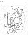
Fig. 1] Fig. 1 is a perspective view illustrating a configuration of anindoor unit 100 of an air-conditioning apparatus according toEmbodiment 1 of the present invention. - [
Fig. 2] Fig. 2 is a sectional view schematically illustrating an internal configuration of theindoor unit 100 ofEmbodiment 1 of the present invention. - [
Fig. 3] Fig. 3 illustrates a configuration of an airflow direction adjustment device disposed near anair outlet 7 inEmbodiment 1 of the present invention. - [
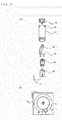
Fig. 4] Fig. 4 illustrates a configuration of atemperature sensor 800 according toEmbodiment 1 of the present invention. - [
Fig. 5] Fig. 5 is a view illustrating the state of a room according toEmbodiment 1 of the present invention when viewed from above. - [
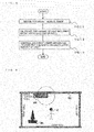
Fig. 6] Fig. 6 is a schematic view (a first view) of an example of a panorama thermal image according toEmbodiment 1 of the present invention. - [
Fig. 7] Fig. 7 is a schematic view (a second view) of an example of a panorama thermal image according toEmbodiment 1 of the present invention. - [
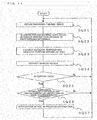
Fig. 8] Fig. 8 is a flowchart showing processes of controlling theindoor unit 100 performed by acontroller 70 according toEmbodiment 1 of the present invention. - [
Fig. 9] Fig. 9 is a view illustrating the state of a room according toEmbodiment 2 of the present invention when viewed from above. - [
Fig. 10] Fig. 10 schematically illustrates an example of a panorama thermal image inEmbodiment 2 of the present invention. - [
Fig. 11] Fig. 11 is a flowchart showing processes of controlling anindoor unit 100 performed by acontroller 70 according toEmbodiment 2 of the present invention. - [
Fig. 12] Fig. 12 is a sectional view schematically illustrating an internal configuration of anindoor unit 100 according toEmbodiment 3 of the present invention. - [
Fig. 13] Fig. 13 is a flowchart showing processes of controlling theindoor unit 100 performed by acontroller 70 according toEmbodiment 3 of the present invention. - [
Fig. 14] Fig. 14 is a view illustrating the state of a room according toEmbodiment 4 of the present invention when viewed from above. - [
Fig. 15] Fig. 15 schematically illustrates an example of a panorama thermal image inEmbodiment 4 of the present invention. - [
Fig. 16] Fig. 16 is a flowchart showing processes of controlling anindoor unit 100 performed by acontroller 70 according toEmbodiment 4 of the present invention. - [
Fig. 17] Fig. 17 is a view illustrating the state of a room according toEmbodiment 5 of the present invention when viewed from above. - [
Fig. 18] Fig. 18 is a view illustrating another example of the state of the room according toEmbodiment 5 of the present invention when viewed from above. - [
Fig. 19] Fig. 19 shows a panorama thermal image in a case where theindoor unit 100 is placed at the location illustrated inFig. 17 . - [
Fig. 20] Fig. 20 shows a panorama thermal image in a case where theindoor unit 100 is placed at the location illustrated inFig. 18 . - [
Fig. 21] Fig. 21 is a flowchart showing processes of controlling theindoor unit 100 performed by acontroller 70 according toEmbodiment 5 of the present invention. - [
Fig. 22] Fig. 22 illustrates an example configuration of an air-conditioning apparatus according to Embodiment 6 of the present invention. - Indoor units of air-conditioning apparatuses (hereinafter referred to as indoor units) according to embodiments of the present invention will be described hereinafter with reference to the drawings. In the drawings including
Fig. 1 , the same reference characters designate the same or like components, and the same holds for the entire description of the embodiments. The configurations of components in the entire description are merely examples, and the present invention is not limited to these examples. In particular, combinations of components are not limited to those in the embodiments, and components in one embodiment are applicable to another embodiment. Similar devices designated by suffixes, for example, may be collectively referred to without the suffixes when these devices do not need to be individually distinguished or specified. The upper side in the drawings will be referred to as an "upper (side)" and the lower side in the drawings will be referred to as a "lower (side)." The right side when viewed from the indoor unit is defined as "right" and the left side when viewed from the indoor unit is defined as "left." In the drawings, the size relationship among components may differ from those in an actual unit. The levels of, for example, temperature and pressure do not depend on a specific relationship with absolute values, and are relatively defined in consideration of, for example, conditions and operations of a system, a device, and other elements. -
Fig. 1 is a perspective view illustrating a configuration of anindoor unit 100 of an air-conditioning apparatus according toEmbodiment 1 of the present invention. First, a schematic configuration of theindoor unit 100 ofEmbodiment 1 will be described. Theindoor unit 100 of Embodiment is a wall-mounted indoor unit placed on a wall surface. - Referring to
Fig. 1 , theindoor unit 100 includes anair inlet 3 at the top of abody 1 and anair outlet 7 at the bottom of thebody 1. Afront panel 2 covers the front surface of thebody 1 such that thebody 1 can be freely covered and uncovered. Thefront panel 2 includes, for example, anotification device 40 that notifies a user of, for example, an operating state with display or the like. Theair outlet 7 includes frontvertical air deflectors 9a and rearvertical air deflectors 9b for adjusting the vertical (upward and downward) airflow (air-sending) directions of conditioned air. InEmbodiment 1, theindoor unit 100 includes atemperature sensor 800 that is located at the bottom of thebody 1 on a side of theair outlet 7 and projects from thebody 1. Thetemperature sensor 800 is an infrared ray sensor (a detector) that detects heat radiated from the surface of a target such as a person or an object while scanning the temperature of the inside of a room that is an air-conditioned space. InFig. 1 , thetemperature sensor 800 is located on the left side on the bottom of thebody 1 of theindoor unit 100. This location, however, does not limit the type and location, for example, of the temperature sensor of the present invention. -
Fig. 2 is a sectional view schematically illustrating an internal configuration of theindoor unit 100 ofEmbodiment 1 of the present invention. Afan 5 forms an air passage 6 in which air in the room flows from theair inlet 3 into thebody 1, passes through anindoor heat exchanger 4, and is blown (sent) from theair outlet 7. Theindoor heat exchanger 4 includes a heatexchanger front portion 4a that is substantially parallel to thefront panel 2, a heat exchanger upper front portion 4b located obliquely above, the front surface of thefan 5, and a heat exchanger upperrear portion 4c located close to, and obliquely above the rear surface of thefan 5. Theindoor heat exchanger 4 exchanges heat between air caused to flow through theindoor heat exchanger 4 by driving thefan 5 and refrigerant passing through the inside of theindoor heat exchanger 4 so as to cool or heat, for example, the air. - A
drain pan 8 is disposed below the heatexchanger front portion 4a so as to receive water (drain water) generated from, for example, frost or dew attached to theindoor heat exchanger 4. Anupper surface 8a of thedrain pan 8 forms a drain pan surface that receives drain water in actual application, and alower surface 8b of thedrain pan 8 serves as a front surface of the air passage 6. - The
controller 70 performs control of the indoor unit 100 (that may include the entire air-conditioning apparatus), such as the airflow rate of thefan 5 and the temperature of refrigerant passing through the indoor heat exchanger 4 (for maintaining the temperature), on the basis of, for example, an instruction from a user (an end user) transmitted through, for example, a remote controller. Thecontroller 70 sends a signal to thenotification device 40 such that an operating state, for example, is displayed, for example. InEmbodiment 1, thecontroller 70 has a function as a wall process controller that determines a portion serving as a wall (especially an outer wall on which the indoor unit is placed) on the basis of the temperature detected by thetemperature sensor 800. Based on the temperature at a location serving as a wall, the amount of heat (a thermal load of a room as an air-conditioned space) supplied from theindoor unit 100 is calculated. In this example, thecontroller 70 of theindoor unit 100 performs control, but another device that can communicate with thecontroller 70 may perform the control. - The
controller 70 ofEmbodiment 1 is, for example, a microcomputer including an arithmetic processing unit for controlling such as a central processing unit (CPU). Thecontroller 70 also includes a recording device (not shown) in which data on processing such as control is stored as a program. The arithmetic processing unit performs processing based on program data for control. Thecontroller 70 may also include clocking means such as a timer so as to perform measurement on time (time of day). -
Fig. 3 illustrates a configuration of an airflow direction adjustment device disposed near theair outlet 7 inEmbodiment 1 of the present invention. As illustrated inFigs. 2 and3 , theindoor unit 100 includes the airflow direction adjustment device that adjusts the air sending direction in which air that has passed through theindoor heat exchanger 4 is sent, near theair outlet 7. Lateral air deflectors 10 (a left lateral air deflector group 10L and a right lateralair deflector group 10R) adjust the air sending direction in the horizontal direction (the lateral direction). The vertical air deflectors 9 (a frontvertical air deflector 9a and a rearvertical air deflector 9b) adjust the air sending direction in the vertical direction (the up-and-down direction). - As illustrated in
Fig. 2 , thevertical air deflectors 9 have a rotation center in parallel to the horizontal direction and are disposed to thebody 1 such that thevertical air deflectors 9 can rotate. The frontvertical air deflectors 9a and the rearvertical air deflectors 9b adjust the angles ofvertical air deflectors 9 by means of a drive means (not shown) with a motor. Thevertical air deflectors 9 are not limited to the illustrated configuration, and the frontvertical air deflector 9a and the rearvertical air deflector 9b may individually rotate by means of different motors. Each of the front and rearvertical air deflectors vertical air deflectors vertical air deflectors 9 is constituted by two deflectors, that is, the frontvertical air deflector 9a and the rearvertical air deflector 9b, but the number of deflectors is not specifically limited. - As illustrated in
Fig. 3 , the right lateralair deflector group 10R includeslateral air deflectors 10a, 10b, ..., and 10g, disposed on thelower surface 8b of thedrain pan 8 such that the right lateralair deflector group 10R can rotate, and aright connecting rod 20R is connected to thelateral air deflectors 10a, 10b, ..., and 10g. The left lateral air deflector group 10L includeslateral air deflectors 10h, 10i, ... and 10n, and a left connectingrod 20L is connected to thelateral air deflectors 10h, 10i, ..., and 10n. The right lateralair deflector group 10R and theright connecting rod 20R form a link mechanism, the left lateral air deflector group 10L and theleft connecting rod 20L form a link mechanism, a right drive means (not shown) and a left drive means 30L are respectively connected to theright connecting rod 20R and theleft connecting rod 20L. - When the
right connecting rod 20R is caused to move in parallel by the right drive means, thelateral air deflectors 10a, 10b, ..., and 10g rotate while being in parallel to each other. Then, when theleft connecting rod 20L is caused to move in parallel by the left drive means 30L, thelateral air deflectors 10h, 10i, ..., and 10n rotate while being in parallel to each other. Thus, air can be sent in the same direction with respect to the entire width of theair outlet 7, in directions away from each other with respect to each half width of theair outlet 7, and in the directions approaching each other with respect to each half width of theair outlet 7. Thelateral air deflectors 10 are not to those illustrated inFig. 3 , for example. For example, the number of thelateral air deflectors 10 is not specifically limited. Thelateral air deflectors 10 may be divided into three or more groups such that each group is rotatably joined to the connecting rod and the connecting rod can move independently in parallel. -
Fig. 4 illustrates a configuration of thetemperature sensor 800 according toEmbodiment 1 of the present invention. Thetemperature sensor 800 detects temperatures at a plurality of locations in a room (inside the room) that is an air-conditioning target. Thetemperature sensor 800 also detects the temperature of a target (a person), for example, in the room. As illustrated inFig. 4(a) , the motor 801 serving as a driver is constituted by, for example, a stepping motor. The motor 801 performs driving based on an instruction from thecontroller 70. Driving power of the motor 801 is transmitted to a power transmission part 803 so that a temperature detector 804 rotates (scans) horizontally. The driving of the motor 801 causes thetemperature sensor 800 to rotate for approximately one turn. The temperature detector 804 is a sensor array in which a line constituted by 32 infrared ray sensors that are vertically aligned is disposed in a horizontal direction. The infrared ray sensors convert heat radiated from the object into an electric signal. The infrared ray sensors has a detection angle of approximately 60 degrees in the vertical direction, but has a narrow detection angle (approximately 8 degrees) in the horizontal direction in detecting the temperature. The temperature detector 804 scans in the horizontal direction so that the temperatures in all the horizontal directions can be detected, thereby creating two-dimensional temperature distribution (a thermal image). - The protective cover 805 protects the temperature detector 804 and forms the lower end of the rotation shaft. A transmission part cover 802 protects the power transmission part 803 and is installed on the
body 1 through an attachment part 806. As illustrated inFig. 4(b) , the transmission part cover 802 includes a stopper 808. On the other hand, the power transmission part 803 has a rib 807. InEmbodiment 1, the rib 807 comes into contact with the stopper 808 while the temperature detector 804 faces toward an installation wall surface. The temperature detector 804 faces in the direction in which the rib 807 projects. The rib 807 and the stopper 808 are used for determining an initial location. InEmbodiment 1, it is assumed that the system requires initial positioning, which will be described later, in order to reduce the cost. However, for example, the system may not require initial positioning (e.g., a pattern, such as a Gray code, which is however expensive, that describes positional information on a motor, a transmission device, or other devices, or a rotary encoder). To detect the temperature corresponding to approximately one turn, 52 temperature detection operations need to be performed during scanning. The detected temperatures are joined in the scanning direction so that panorama thermal image indicating two-dimensional temperature distribution is generated. In the following description, thetemperature sensor 800 performs scanning and temperature detection for generating a panorama thermal image. In this example, 52 temperature detection operations are performed. In thetemperature sensor 800 ofEmbodiment -
Fig. 5 is a view illustrating the state of a room according toEmbodiment 1 of the present invention when viewed from above.Fig. 5 shows an end user U and an object O1 in order to illustrate the positional relationship in the room that is an air-conditioned space. InEmbodiment 1, theindoor unit 100 is placed on the outer wall. The season is winter with low outdoor temperatures. The left wall and the right wall are defined when the inside of the room is seen from the indoor unit 100 (temperature sensor 800). - After the operation of the air-conditioning apparatus has started, the
controller 70 applies a stepped pulse to the motor 801 so that the motor 801 rotates counterclockwise. The location at which the rib 807 comes into contact with the stopper 808 and stops rotating is defined as an initial location. At the initial location, the temperature detector 804 faces a direction substantially opposite to the indoor direction. Thus, the temperature of the outer wall serving as the installation wall is detected. Since thetemperature sensor 800 ofEmbodiment 1 projects from thebody 1, it is possible to detect the temperature of the outer wall serving as the installation wall. The temperature detector 804 cannot be directed to a portion covered with the stopper 808, but this portion can be covered from the angle of detection of thetemperature sensor 800 in the horizontal direction. - After initial positioning, the
temperature sensor 800 is caused to detect the temperature. Temperature data having detection angles of 7 degrees in the horizontal direction and 60 degrees in the vertical direction where t = 0 is obtained. In addition, a stepped pulse for causing the temperature detector 804 to rotate to 7 degrees is applied to the motor 801, and thetemperature sensor 800 is caused to rotate clockwise, thereby changing the angle of temperature detection. After the angle change, a second (t = 1) temperature detection is performed. This detection is repeated as t = 2, 3, ... with the angle of thetemperature sensor 800 being repeatedly changed. The temperature detection is performed until the rib 807 comes into contact with the stopper 808, and then, the temperature detection operation for one turn is completed. To perform the temperature detection for one turn, thetemperature sensor 800 performs temperature detection at least 52 times (up to t = 51). In the foregoing manner, a panorama thermal image with 32x52 pixels can be obtained. Then, thetemperature sensor 800 is caused to rotate counterclockwise and performs the similar operation. As described above, oscillating rotation relative to the stopper 808 is repeated so as to detect the indoor temperature, thereby obtaining panorama thermal image data. Since the principle is the same, only a panorama thermal image in the clockwise rotation will be described below. -
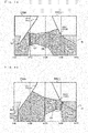
Figs. 6 and 7 schematically illustrate examples of a panorama thermal image inEmbodiment 1 of the present invention.Figs. 6 and 7 show panorama thermal images in the case of rotation for one turn with a horizontal detection angle of 7 degrees.Fig. 6 shows a panorama thermal image in a state in which thevertical air deflectors 9 are housed in thebody 1. On the other hand,Fig. 7 shows a panorama thermal image in a state in which thevertical air deflectors 9 operate and move downward. In the drawings, 100v denotes an image (hereinafter referred to as an indoor unitthermal image 100v) in a parallel thermal image of theindoor unit 100.Reference character 9v denotes an image (hereinafter referred to as a vertical air deflectorthermal image 9v) in the parallel thermal image of thevertical air deflectors 9.Reference character 7v denotes an image (hereinafter referred to as an air outletthermal image 7v) in the parallel thermal image of theair outlet 7. SinceFigs. 6 and 7 are schematic views, images are simplified. However, actual panorama thermal images are displayed with especially horizontal lines being curved. InFigs. 6 and 7 , ranges detected by a conventional temperature sensor (motion detector) are indicated by dotted lines. Although the indoor unitthermal image 100v of theindoor unit 100 is located in upper portions inFigs. 6 and 7 , the left front, left rear, right front, and right rear of the surface of thebody 1 are described for easing description of the positional relationship. - Referring to
Figs. 6 and 7 , an operation of thetemperature sensor 800 will be specifically described. Here, it is assumed that the initial location is at the left rear side. Thetemperature sensor 800 of theindoor unit 100 scans a closed room including the end user U and the object O1. At t = 0, the temperature of the outer wall serving as the installation wall and theindoor unit 100 can be detected. With scanning at t = 1, 2, and 3, ..., the boundary (edge) can be determined based on the temperature difference in, for example, temperature between the outer wall and the left wall around t = 13. A conventional motion detector, for example, has a narrow detection range, and thus cannot determine the presence of an edge or the like. - Around t = 25, which is an approximately middle, the temperature of the end user U is detected and the presence thereof is detected. Around t = 30, the temperature of the object O1 is detected, and the presence thereof is detected. Around t = 40, the boundary between the outer wall and the right wall is detected. The conventional motion detector, for example, cannot detect the temperature at the boundary. In this situation, the
temperature sensor 800 ofEmbodiment 1 can determine the rearvertical air deflector 9b. As a result, the temperatures of theair outlet 7 and thevertical air deflectors 9 can be detected as the air outletthermal image 7v and the vertical air deflectorthermal image 9v. In subsequent processes, theair outlet 7, thevertical air deflectors 9, and the installation wall surface are seen. In the foregoing manner, the temperature of the installation wall (outer wall), which is most important inEmbodiment 1, can be detected. -
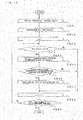
Fig. 8 is a flowchart showing processes of controlling theindoor unit 100 performed by thecontroller 70 ofEmbodiment 1 of the present invention. In subsequent Embodiments, a plurality of processes performed by thecontroller 70 will be described, where the processes may be performed in a time-division manner with processes based on the flowchart ofFig. 8 or in parallel by another controlling device, for example. First, at SQ11, thecontroller 70 obtains panorama thermal image data based on an operation of thetemperature sensor 800. The panorama thermal image data can be obtained in the manner described above. At SQ12, a necessary amount of heat including the outer wall is calculated based on the panorama thermal image data. The thermal calculation may employ various known techniques. The sensible temperature may be calculated by using, but not limited to, the temperature of the outer wall serving as the installation wall. Then, at SQ13, based on the calculated amount of heat, the air-conditioning apparatus (e.g., the evaporating temperature and the condensing temperature of the indoor heat exchanger 4) and the airflow rate of thefan 5, for example, are controlled. The foregoing process is repeatedly performed during operation of the air-conditioning apparatus. - As described above, in the
indoor unit 100 ofEmbodiment 1, thetemperature sensor 800 projects from thebody 1 and is caused rotate by approximately 360 degrees for temperature detection. Thus, the temperature can be detected in a wide range including the installation wall (the outer wall). In addition, even in cases where the outer wall is cold or warm because of the outdoor air, appropriate thermal calculation can be performed, thereby enabling air at more comfortable temperature, for example, to be sent into the room. - For example, in
Fig. 5 , the amount of heat in a room having a height of 2.5 m and an area corresponding to 10 tatami mats (approximately 39 m3 (cubic meters)) is examined. Here, the case of increasing the temperature of the room by 1 degree C will be discussed. For example, suppose the specific heat of the air is 1.006 [J/g·K] and the weight of air per 1 m3 is 1293 g. Then, the necessary amount of heat is 1.006 [J/(g·K)] × 1293 [g/m3] × 1 [K] × 39 [m3] = approximately 51000 J (approximately 212 kcal). - At step SQ12 described above, the easiest method for calculating the amount of heat, for example, is a method of calculating the temperature based on a comparison between the temperature obtained by simply averaging the temperatures of the left wall, the right wall, the back wall, and the outer wall serving as the installation wall and a set temperature. The amount of heat is calculated after correction of, for example, the temperature of the walls in some cases. However, this calculation is complicated, and description thereof is omitted. In a conventional technique, the temperature of the outer wall serving as the installation wall cannot be included in calculation, but in
Embodiment 1, the temperature of the outer wall can be included in calculation. For example, suppose the set temperature is 20 degrees C, and the temperatures of the left wall, the right wall, and the back wall are 17 degrees C. The outer wall serving as the installation wall is 9 degrees C because the outer wall is separated from the outdoor air. - In this case, the amount of heat obtained by the conventional calculation and the amount of heat obtained in
Embodiment 1 are: - Conventional calculation: (20 - (17 + 17 + 17)/3) × 51000 [J/K] = 153000 J
- Embodiment 1: (20 - (17 + 17 + 17 + 9)/4)*51000 [J/K] = 255000 J.
- The, the amount of heat obtained by the conventional calculation is in short, that is, smaller by 100000 J than the amount of heat obtained in
Embodiment 1 in consideration of the temperature of the outer wall. In the conventional calculation, various corrections are needed because the temperature of the outer wall is unknown. As a result, the calculation of the amount of heat is complicated and calculation bycontroller 70 requires a large number of processes. In addition, the processing speed slightly decreases. InEmbodiment 1, the temperature of the outer wall serving as the installation wall is directly detected and reflected in thermal calculation. Thus, a smaller number of corrections are needed, and the number of processes can be reduced. Furthermore, since the temperature of the outer wall is obtained not by correction but by detection, the required accuracy in the amount of heat can be enhanced. - In a case where the installation wall is the outer wall as in
Embodiment 1, the detection is easily affected by the temperature of outdoor air. For example, if the outside of the room is cold, it is hypothesized that the temperature sensible by a person is low. Thus, the heat higher than the set temperature may be taken into the room. For example, in the above-described thermal calculation of the average temperature of the walls, the weight of the temperature of the outer wall may be doubled ((i.e., left wall + right wall + back wall + installation wall surface × 2)/5). The assignment of weight to the temperature of the outer wall enables thermal calculation to be closer to the sensible temperature, thereby making the room comfortable. - As described above, the temperature of the installation wall surface (the outer wall) can be directly detected so that thermal calculation can be accurately performed even in seasons such as cold winter with the cold outer wall and hot summer with the warmed outer wall. In addition, since the detected temperature of the outer wall can be used for adjustment of the sensible temperature of the end user, air can be sent into the room at a more comfortable airflow rate, for example.
-
Fig. 9 is a view illustrating the state of a room according toEmbodiment 2 of the present invention when viewed from above. It is assumed that the wall separating the room ofEmbodiment 2 serving as a space of an air-conditioning target has awindow 02 in the installation wall surface. Heat easily escapes from the room through the window. In view of this, inEmbodiment 2, anindoor unit 100 that can notify an end user of opening or closing of a curtain will be described. Here, a configuration of theindoor unit 100 ofEmbodiment 2 is substantially the same as the configuration of theindoor unit 100 described inEmbodiment 1. InEmbodiment 2, acontroller 70 has a function as a window process controller, for example, determines a portion serving as a window based on panorama thermal image data, and performs processes regarding the window and the curtain. -
Fig. 10 schematically illustrates an example of a panorama thermal image inEmbodiment 2 of the present invention. As illustrated inFig. 10 , atemperature sensor 800 of theindoor unit 100 ofEmbodiment 2 can detect the temperature of thewindow 02 in the installation wall surface. Here, a case wherewindow 02 curtain is provided will be described. -
Fig. 11 is a flowchart showing processes of controlling theindoor unit 100 performed by thecontroller 70 ofEmbodiment 2 of the present invention. - First, at SQ21, the
controller 70 obtains panorama thermal image data based on the operation of thetemperature sensor 800. Since the process in SQ21 is the same as that in SQ11 described inEmbodiment 1, processes subsequent to SQ22 may be performed by using panorama thermal image data obtained by the process at SQ11. - At SQ22, it is determined whether there is a region showing a temperature difference greater than or equal to a predetermined difference. In general, the window is warmer than the wall in summer, and colder than the wall in winter. This is because the window is more susceptible to the influence of outdoor air than the wall. Then, at SQ23, for a portion serving as a wall, an outdoor-air temperature region is extracted. Thereafter, at SQ24, a window region is extracted (i.e., a portion serving as the window is detected).
- Once the window region is extracted, the
controller 70 monitors a change with time in the temperature at the window region, thereby determining opening/closing of the curtain. For example, if the curtain is open, it is necessary to supply the amount of heat more than that obtained by thermal calculation. In view of this, in order not dissipate heat from the room through the window, the curtain needs to be closed. - At SQ25, it is determined whether the curtain in the window region is open based on the temperature detected by the
temperature sensor 800. If it is determined that the curtain is open, then it is determined at SQ26 whether the difference between the set temperature and the temperature of the window (or the wall) is greater than or equal to a predetermined temperature difference. If the difference is determined to be greater than or equal to the predetermined temperature difference, at SQ27, a signal of instructing that the curtain is closed is transmitted to thenotification device 40, and the end user is notified of the signal. Here, the notification is provided by displaying in thenotification device 40, but may be provided by means of sound (voice). Alternatively, the notification may be provided by, for example, displaying on a connected remote controller or other components. - As described above, the
indoor unit 100 ofEmbodiment 2 can obtain the same advantages as those of theindoor unit 100 ofEmbodiment 1. In addition, since a window region of the installation wall surface (the outer wall) can be extracted, the window can be monitored. The monitoring of the window can provide a notification of closing the curtain in a case where the temperature difference between the room and the outdoor air is large, and dissipation of heat from the window can be reduced. Thus, energy can be saved. -
Fig. 12 is a sectional view schematically illustrating an internal configuration of anindoor unit 100 according toEmbodiment 3 of the present invention. InFig. 12 , components designated by the same reference signs as those inFig. 2 are assumed to perform operations and processes, for example, similar to those described inEmbodiment 1. - An intake air temperature condition detector 60 includes a temperature sensor 61 that detects a dry-bulb temperature (hereinafter referred to as a temperature) near an
air inlet 3 and a humidity sensor 62 that detects a relative humidity (hereinafter referred to as a humidity) near theair inlet 3. The temperature sensor 61 and the humidity sensor 62 are disposed near theair inlet 3. Acontroller 70 ofEmbodiment 3 calculates a dewpoint temperature (a temperature at which steam changes to water), on the basis of the temperature detected by the temperature sensor 61 and the humidity detected by the humidity sensor 62. Here, a method for calculating the dewpoint temperature, such as a method based on "humidity chart" and a method based on the table in JIS8806, are not specifically limited. - In
Embodiment 3, to prevent dew condensation on airflow direction adjustment devices (especially the vertical air deflectors 9), a portion serving asvertical air deflectors 9 is determined based on the parallel thermal image data, and the state of dew condensation is determined based on the temperature at thevertical air deflectors 9 and the dewpoint temperature. Based on the determination, an air deflector driver (not shown) is driven, thereby providing the function as a deflector process controller that controls thevertical air deflectors 9. - First, dew condensation will be described. For example, the case of cooling a room at a temperature of 30 degrees C with a humidity of 80% will be described. The
indoor unit 100 sucks air at a temperature of 30 degrees C with a humidity of 80% into thebody 1 through theair inlet 3. The dewpoint temperature in this case is 26 degrees C. Thus, this air is cooled to 26 degrees C or lower, part of steam becomes dew (water). - The
controller 70 obtains, as data, the temperature and humidity of a room from the intake air temperature condition detector 60. From the data on the temperature and the data on the humidity, the temperature of air to be sent from theair outlet 7 is determined based on the temperature, and a refrigeration cycle is operated in accordance with the determined air temperature. Here, the blowing temperature is 20 degrees C. At this time, dew is generated mainly in theindoor heat exchanger 4, but dew generated in thebody 1 is collected. Air at a temperature of 20 degrees C with a humidity of 100% is sent from theair outlet 7. - Here, during operation, possible dew condensation on airflow direction adjustment devices (especially
vertical air deflectors 9 outside the body 1) cannot be collected. Thevertical air deflectors 9 themselves are kept at around the blowing temperature (20 degrees C). For example, depending on the way of sending air, thevertical air deflectors 9 might come into contact with the room air (at a temperature of 30 degrees C and a humidity of 80%) during operation. Thevertical air deflectors 9 might also come into contact with the room air in a case where an air current passing in a path different from an air passage 6. The room air is cooled by air from thebody 1 and changes into air at a temperature of 26 degrees C or less with a humidity of about 100%. When this air strikes thevertical air deflectors 9, condensation can occur. Water drops generated by dew condensation on thelateral air deflectors 10 of thebody 1 might also come into contact with thevertical air deflectors 9. In both of these cases, it is common that the temperature and humidity of room air are high when dew is generated. - On the other hand, dew condensation can be prevented immediately before dew condensation is generated on the
vertical air deflectors 9. Specifically, the operation of the air-conditioning apparatus is stopped, and thevertical air deflectors 9 are temporarily housed in thebody 1 and dried for a short period so that condensation can be prevented. While thevertical air deflectors 9 are housed in thebody 1, the operation of the air-conditioning apparatus is stopped and air is not sent into the room. Thus, comfort cannot be provided to the end user. - For example, since the temperature of the
vertical air deflectors 9 cannot be detected in the conventional technique, the operation stop of the air-conditioning apparatus for preventing dew condensation is performed at regular intervals. Thus, the efficiency might be degraded by regularly stopping the operation without dew condensation, and water drops are generated by not stopping the operation until a predetermined time has elapsed after generation of dew condensation. In theindoor unit 100 ofEmbodiment 3, the temperature of thevertical air deflectors 9 is detected so that the operation for preventing dew condensation on thevertical air deflectors 9 can be performed not by time management but is performed when necessary. -
Fig. 13 is a flowchart showing processes of controlling theindoor unit 100 performed by thecontroller 70 according toEmbodiment 3 of the present invention. After an operation has started, at SQ31, based on the temperature and humidity of the room detected by the intake air temperature condition detector 60, the temperature of air that is to pass through theindoor heat exchanger 4 and to be sent from theair outlet 7 is determined. Then, at SQ32, a parallel thermal image is obtained and a region corresponding to thevertical air deflectors 9 is extracted so that the temperature of thevertical air deflectors 9 is detected. Thereafter, at SQ33, it is determined whether the temperature of thevertical air deflectors 9 is greater than or equal to the temperature of air at theair outlet 7 that relates to determination. If it is determined that the temperature of thevertical air deflectors 9 is not greater than or equal to the temperature of air at theair outlet 7, the process returns to SQ31. - If it is determined that the temperature of the
vertical air deflectors 9 is greater than or equal to the temperature of air at theair outlet 7, at SQ34, it is determined whether the temperature difference (difference in deflector temperature) between the temperature of thevertical air deflectors 9 and the temperature of air at theair outlet 7 for determination is greater than or equal to a predetermined deflector standard temperature. Here, the deflector standard temperature is set at a temperature that is considered abnormal as the temperature of thevertical air deflectors 9. If it is determined that the difference of deflector temperature is not greater than or equal to the deflector standard temperature, the process returns to SQ31. If it is determined that the difference of deflector temperature is greater than or equal to the deflector standard temperature, at SQ35, the operation of the air-conditioning apparatus (the indoor unit 100) is stopped, and theair outlet 7 is closed by thevertical air deflectors 9. - After the
air outlet 7 has been closed, at SQ36, it is determined whether a predetermined time has elapsed. If the predetermined time has not elapsed, the process waits for the lapse. If it is determined that the predetermined period has lapsed, at SQ37, the operation of the air-conditioning apparatus is started, and thevertical air deflectors 9 are opened. Then, the process returns to SQ31. - Here, in SQ31 through SQ33, the temperature decreasing state of the
vertical air deflectors 9 may be monitored. Alternatively, the temperature decreasing state may wait based on time. In addition, SQ36, after a predetermined time is elapsed, the temperature of thevertical air deflectors 9 is detected, and an operation of determining whether thevertical air deflectors 9 are dried or not based on the detected temperature. If it is determined that thevertical air deflectors 9 are not dried, drying is performed by further extending a wait time. - As described above, the
indoor unit 100 of theEmbodiment 3 can obtain the same advantages as those of theindoor unit 100 ofEmbodiment 1. In addition, since the air-outlet set temperature and the temperature of thevertical air deflectors 9 can be detected and directly monitored, the state of dew condensation on thevertical air deflectors 9 can be accurately determined. Thus, the vertical air deflectors 9 (the airflow direction adjustment devices) can be dried in an optimum time. Since thevertical air deflectors 9 can determine the state before dew condensation, it is possible to prevent at least dew (water) from dropping onto the room (e.g., the floor) from thebody 1. In addition, it is possible to determine whether the temperature of outlet air is abnormal. Furthermore, the position of thevertical air deflectors 9 can be determined so that it is possible to determine whether thevertical air deflectors 9 are at the position as specified. It is also possible to detect abnormality such as a case where the end user forces to touch thevertical air deflectors 9 by hand. -
Fig. 14 is a view illustrating the state of a room according toEmbodiment 4 of the present invention when viewed from above. It is assumed that a door (an entrance) is provided on each wall partitioning a room that is an air-conditioning target space inEmbodiment 4. Here, adoor 03, adoor 04, adoor 05, and adoor 06 are respectively provided at the left wall, the right wall, the back wall, and the installation wall of anindoor unit 100, respectively. InEmbodiment 4, the installation wall is not an outer wall facing, for example, outdoor air but a wall partitioning the room from a neighboring room. The type of each door (e.g., an outward-opening door, an inward-opening door, or a sliding door) is not specifically limited. A configuration of theindoor unit 100 ofEmbodiment 4 is substantially the same as the configuration of theindoor unit 100 described inEmbodiment 1. InEmbodiment 4, acontroller 70 has a function as an entrance process controller, for example, determines a position serving as a door that is an entrance, on the basis of panorama thermal image data, and performs processes that relate to the doors. -
Fig. 15 schematically illustrates an example of a panorama thermal image inEmbodiment 4 of the present invention. In theindoor unit 100 ofEmbodiment 4, thetemperature sensor 800 detects all the regions corresponding to thedoor 03 through thedoor 06 in the room and detects the temperatures in the regions. In particular, in theindoor unit 100 ofEmbodiment 4, since the scanning range of thetemperature sensor 800 is large, thedoor 06 of the installation wall can be detected. -
Fig. 16 is a flowchart showing processes of controlling theindoor unit 100 performed by acontroller 70 ofEmbodiment 4 of the present invention. When an operation starts, thecontroller 70 obtains panorama thermal image data on the basis of the operation of atemperature sensor 800 at SQ41. Then, at SQ42, regions corresponding to all the doors are extracted, and the doors are determined. Thereafter, at SQ43, processes for the doors are performed from the door where n = 1 with reference to the number n (where n = 1, 2, 3, and 4 in Embodiment 4) assigned to the doors. - Then, at SQ44, it is determined whether a door is open. If it is determined that the door is not open (i.e., is closed), a process for this door is finished. On the other hand, if it is determined that the door is open, this detection means that the temperature on the farside of the door is detected. Thus, at SQ45, the temperature in the extracted region corresponding to the door is detected. Subsequently, at SQ46, it is determined whether the temperature difference (door temperature difference) between the temperature at the region corresponding to the door n and the room is greater than or equal to a predetermined temperature difference (standard door temperature difference). If it is determined that the door temperature difference is not greater than or equal to the standard door temperature difference, the process on the door n is finished. On the other hand, if it is determined that the door temperature difference is greater than or equal to the standard door temperature difference, output of the
indoor unit 100, for example, is increased at SQ47 so that the room including the farside on the door is air-conditioned. Then, at SQ48, n = n + 1 is established. At SQ49, it is then determined whether processes on all the doors are finished. If it is determined that the processes are not finished, the process returns to SQ44, and a process is performed on the next door. If it is determined that the processes are finished, processes on the doors are terminated. - As described above, in the
indoor unit 100 ofEmbodiment 4, thetemperature sensor 800 can detect all the doors (especially the door at the installation wall) of the room. If one of the doors is open, for example, the temperature in a region on the farside of the door can be detected. For example, in a case where the temperature in a region on the farside of the door is lower than the room temperature in a heating operation or a case where the temperature in a region on the farside of the door is higher than the room temperature in a cooling operation, the room including the region on the farside of the room can be air-conditioned. Thus, comfort of the end user can be enhanced. Here, at SQ46, in a case where the temperature in a region on the farside of the door is higher than the room temperature in a heating operation or a case where the temperature in a region on the farside of the door is lower than the room temperature in a cooling operation, energy saving may be tried by reducing output (the amount of supplied heat) from theindoor unit 100. In a case where the temperature difference between the region on the farside of the door and the room temperature is large, notification of opening the door can be issued. -
Fig. 17 is a view illustrating the state of a room according toEmbodiment 5 of the present invention when viewed from above.Fig. 18 is a view illustrating another example of the state of the room according toEmbodiment 5 of the present invention when viewed from above. InFig. 17 , anindoor unit 100 is placed on the left wall side. On the other hand, inFig. 18 , theindoor unit 100 is placed on the right wall side. InEmbodiment 5, acontroller 70 determines walls on both sides of the installation wall and the floor based on panorama thermal image data, and has a function as an installation location process controller that derives the installation location of theindoor unit 100 in a room based on the determination. -
Fig. 19 shows a panorama thermal image in a case where theindoor unit 100 is placed at the location illustrated inFig. 17 .Fig. 20 shows a panorama thermal image in a case where theindoor unit 100 is placed at the location illustrated inFig. 18 . The boundary between the installation wall and the left wall is defined as anedge 07. The boundary between the installation wall and the right wall is defined as anedge 08. Here, the temperature of theedge 07 is detected around t = 10 inFig. 19 and around t = 5 inFig. 20 . The temperature of theedge 08 is detected around t = 43 inFig. 19 and around t = 41 inFig. 20 . InFigs. 19 and 20 , thevertical air deflectors 9 are housed in thebody 1. -
Fig. 21 is a flowchart showing processes of controlling theindoor unit 100 performed by thecontroller 70 ofEmbodiment 5 of the present invention. When an operation starts, thecontroller 70 obtains panorama thermal image data on the basis of the operation of atemperature sensor 800 at SQ51. Then, at SQ52, theedge 07 as the boundary between the installation wall and the left wall and theedge 08 as the boundary between the installation wall and the right wall are detected. In addition, times when these boundaries are detected are recorded. - Thereafter, at SQ53, the angle to each wall surface is calculated. First, suppose the detection time of the
edge 07 or theedge 08 is t, conversion into an angle from the initial location of theedge 07 or theedge 08 based on the detection time t is performed. InEmbodiment 5, the relationship:
where E is an edge detection angle is established. - Then the distance between the body 1 (the temperature sensor 800) and each edge is obtained as:


where K (known) is the distance from the installation wall to thetemperature sensor 800. - The height of the
indoor unit 100 installed on the installation wall can also be derived. For example, on the basis of thermal images shown inFigs. 19 and 20 , contact point between theedge 07 or theedge 08 and the floor can be detected. For example, suppose the angle in the vertical direction in a case where a contact point between theedge 07 and the floor is F,
is established. In the foregoing manner, since the height of the installation location of theindoor unit 100 on the installation wall from the floor is determined, air can be caused to strike the wall when necessary. Detailed description thereof is omitted. - As described above, in the
indoor unit 100 ofEmbodiment 5, thetemperature sensor 800 can detect theedge temperature sensor 800 and theedge indoor unit 100. For example, to adjust the direction of air flow at the highest temperature, the installation location of theindoor unit 100 can be utilized. - For example, in the room illustrated in
Fig. 17 , since theindoor unit 100 is placed on the left wall side, it can be recognized that no person is present on the left of theindoor unit 100. On the other hand, in the room illustrated inFig. 18 , since theindoor unit 100 is placed on the right wall side, it can be recognized that no person is present on the right. After the operation has started and until the room temperature reaches a set temperature, the temperature adjustment is performed including the wall. Once air-conditioning is stabilized, air is not sent to the wall and but to a person. At this time, air is not sent to the left inFig. 17 and to the right inFig. 18 so that more comfortable air can be sent to the person. -
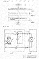
Fig. 22 illustrates an example configuration of an air-conditioning apparatus according to Embodiment 6 of the present invention.Fig. 22 shows the air-conditioning apparatus as an example of a refrigeration cycle apparatus. InFig. 22 , components already described with reference toFig. 2 , for example, perform the similar operations. In the air-conditioning apparatus illustrated inFig. 22 , anoutdoor unit 200 and theindoor unit 100 described in the Embodiments above are connected to each other by pipes including agas refrigerant pipe 300 and a liquidrefrigerant pipe 400. Theoutdoor unit 200 includes acompressor 210, a four-way valve 220, anoutdoor heat exchanger 230, and anexpansion valve 240. - The
compressor 210 compresses sucked refrigerant and discharges the compressed refrigerant. Thecompressor 210 may change the capacity (the amount of refrigerant that is send in a unit time) by, but not limited to, optionally changing the operating frequency with, for example, an inverter circuit. The four-way valve 220 is a valve that switches a refrigerant flow between a cooling operation and a heating operation, for example. - The
outdoor heat exchanger 230 of Embodiment 6 exchanges heat between the refrigerant and air (outdoor air). For example, in the heating operation, theoutdoor heat exchanger 230 serves as an evaporator and causes refrigerant to evaporate and vaporize. In the cooling operation, theoutdoor heat exchanger 230 serves as a condenser and condenses and liquefies the refrigerant. - The
expansion valve 240 such as an expansion device (a flow rate controlling means) reduces the pressure of refrigerant and causes the refrigerant to expand. For example, in a case where theexpansion valve 240 is an electronic expansion valve, for example, theexpansion valve 240 adjusts the opening degree on the basis of an instruction from, for example, a controller (not shown). Anindoor heat exchanger 4 exchanges heat between air to be conditioned and refrigerant, for example. The indoor heat exchanger 110 serves as a condenser and condenses and liquefies refrigerant in the heating operation. The indoor heat exchanger 110 serves as an evaporator and causes refrigerant to evaporate and vaporize in the cooling operation. - As described above, since the air-conditioning apparatus can be configured by using
indoor unit 100 described in Embodiments above (i.e., the temperature of the installation wall can be directly detected), the temperature detection range in a room to be an air-conditioned space can be expanded, thereby providing a heating operation and a cooling operation with comfort while achieving energy saving. - 1: body, 2: front panel, 3: air inlet, 4: indoor heat exchanger, 4a: heat exchanger front portion, 4b: heat exchanger upper front portion, 4c: heat exchanger upper rear portion, 5: fan, 6: air passage, 7: air outlet, 8: drain pan, 8a: upper surface, 8b: lower surface, 9: vertical air deflector, 9a: front vertical air deflector, 9b: rear vertical air deflector, 10: lateral air deflector, 10L: left lateral air deflector group, 10R: right lateral air deflector group, 10a to 10n: lateral air deflector, 20L: left connecting rod, 20R: right connecting rod, 30L: left drive means, 40: notification device, 60: intake air temperature condition detector, 61: temperature sensor, 62: humidity sensor, 70: controller, 100: indoor unit, 200: outdoor unit, 210: compressor, 220: four-way valve, 230: outdoor heat exchanger, 240: expansion valve, 300: gas refrigerant pipe, 400: liquid refrigerant pipe, 800: temperature sensor, 801: motor, 802: transmission part cover, 803: power transmission part, 804: temperature detector, 805: protective cover, 806: attachment part, 807: rib, 808: stopper, 7v: air outlet thermal image, 9v: vertical air deflector thermal image, 100v: indoor unit thermal image.
Claims (13)
- An indoor unit (100) of an air-conditioning apparatus, the indoor unit (100) having a body (1) placed on a wall surface of a room that is an air-conditioned space, the indoor unit (100) comprising
a temperature sensor (800) disposed at a position projecting from the body (1), and including a temperature detector (804) configured to detect a temperature based on heat radiation from a target and a driver (801) configured to cause the temperature detector (804) to rotate, the position being a place where the temperature sensor (800) is capable of detecting a temperature in all the horizontal directions by rotating the temperature detector (804). - The indoor unit (100) of the air-conditioning apparatus of claim 1, wherein the temperature sensor (800) further includes a stopper (808) that defines a detection start location and a detection end location of the temperature detector (804).
- The indoor unit (100) of the air-conditioning apparatus of claim 1 or 2, further comprising a controller (70) configured to determine, as being the object, a wall on which the body (1) is placed based on the temperature detected by the temperature sensor (800).
- The indoor unit (100) of the air-conditioning apparatus of claim 3, wherein the controller (70) calculates an amount of heat to be supplied to the room including a temperature at a location determined as the wall on which the body (1) is placed, and based on the calculated amount of heat, performs air-conditioning control.
- The indoor unit (100) of the air-conditioning apparatus of claim 3 or 4, wherein the controller (70) derives a sensible temperature in the room based on the temperature at the location determined as the wall on which the body (1) is placed.
- The indoor unit (100) of the air-conditioning apparatus of any one of claims 1 to 5, further comprising a controller (70) configured to determine a window as being the target based on the temperature detected by the temperature sensor (800).
- The indoor unit (100) of the air-conditioning apparatus of any one of claims 1 to 6, further comprising:an airflow direction adjustment device configured to adjust a direction in which air that has passed through the body (1) is blown;an air temperature condition detector (60) configured to detect a temperature and a humidity of air in the room; anda controller (70) configured to determine the airflow direction adjustment device as being the target based on the temperature detected by the temperature sensor (800), and determine a state of dew condensation on the airflow direction adjustment device based on a temperature at a location determined as the airflow direction adjustment device and the temperature and humidity of air in the room.
- The indoor unit (100) of the air-conditioning apparatus of any one of claims 1 to 7, further comprising a controller (70) configured to determine, as being the target, an entrance of the room based on the temperature detected by the temperature sensor (800).
- The indoor unit (100) of the air-conditioning apparatus of claim 8, wherein the controller (70) determines an opening condition of the entrance based on a temperature at a location determined as the entrance.
- The indoor unit (100) of the air-conditioning apparatus of claim 8 or 9, wherein
if a temperature difference between a temperature at a location determined as the entrance and a temperature in the room is greater than or equal to a predetermined temperature difference, the controller (70) increases or decreases an output of the indoor unit (100). - The indoor unit (100) of the air-conditioning apparatus of any one of claims 1 to 10, further comprising
a controller (70) configured to determine, as being the target, the wall on which the target is placed, walls adjacent to the wall on which the body (1) is placed and a floor based on the temperature detected by the temperature sensor (800) so as to derive a distance from a location at which the body (1) is placed to the walls adjacent to the wall on which the body (1) is placed and a height of the location at which the body (1) is placed from the floor. - The indoor unit (100) of the air-conditioning apparatus of claim 11, further comprising
an airflow direction adjustment device configured to adjust a direction in which air that has passed through the body (1) is blown, wherein
the airflow direction adjustment device is controlled such that air is not blown to a location where no person is present. - An air-conditioning apparatus for performing air-conditioning, comprising:the indoor unit (100) as dependent on any one of claims 1 to 12; andan outdoor unit (200).
Applications Claiming Priority (1)
| Application Number | Priority Date | Filing Date | Title |
|---|---|---|---|
| JP2014130666A JP6242300B2 (en) | 2014-06-25 | 2014-06-25 | Air conditioner indoor unit and air conditioner |
Publications (3)
| Publication Number | Publication Date |
|---|---|
| EP2960588A2 true EP2960588A2 (en) | 2015-12-30 |
| EP2960588A3 EP2960588A3 (en) | 2016-01-13 |
| EP2960588B1 EP2960588B1 (en) | 2022-06-08 |
Family
ID=53269334
Family Applications (1)
| Application Number | Title | Priority Date | Filing Date |
|---|---|---|---|
| EP15169665.5A Active EP2960588B1 (en) | 2014-06-25 | 2015-05-28 | Indoor unit of air-conditioning apparatus and & air-conditioning apparatus |
Country Status (4)
| Country | Link |
|---|---|
| US (1) | US10024563B2 (en) |
| EP (1) | EP2960588B1 (en) |
| JP (1) | JP6242300B2 (en) |
| CN (2) | CN105202690B (en) |
Cited By (4)
| Publication number | Priority date | Publication date | Assignee | Title |
|---|---|---|---|---|
| CN110794701A (en) * | 2019-11-27 | 2020-02-14 | 广东美的制冷设备有限公司 | Environment control method and device based on air-conditioning robot |
| EP3587945A4 (en) * | 2017-02-22 | 2020-03-04 | Mitsubishi Electric Corporation | AIR CONDITIONING DEVICE |
| EP4001789A4 (en) * | 2019-08-14 | 2022-10-26 | Samsung Electronics Co., Ltd. | AIR CONDITIONER AND ITS CONTROL METHOD |
| US20250198642A1 (en) * | 2022-08-04 | 2025-06-19 | Mitsubishi Electric Corporation | Indoor unit and air conditioner |
Families Citing this family (34)
| Publication number | Priority date | Publication date | Assignee | Title |
|---|---|---|---|---|
| JP6242300B2 (en) * | 2014-06-25 | 2017-12-06 | 三菱電機株式会社 | Air conditioner indoor unit and air conditioner |
| US9982906B2 (en) * | 2014-10-23 | 2018-05-29 | Vivint, Inc. | Real-time temperature management |
| CN107278255B (en) * | 2016-02-03 | 2019-12-31 | 三菱电机株式会社 | Indoor unit of air conditioner |
| JP6730074B2 (en) * | 2016-04-25 | 2020-07-29 | 株式会社東芝 | Air conditioning control device, air conditioning control system, air conditioning control method, and air conditioning control program |
| CN106197695B (en) * | 2016-06-30 | 2018-07-03 | 国网山东省电力公司济南市历城区供电公司 | High-tension switch cabinet integral intelligent temperature measuring equipment |
| CN107036169A (en) * | 2017-05-02 | 2017-08-11 | 深圳沃海森科技有限公司 | With the air-conditioning system of indoor solid matter constant temperature |
| CN208831238U (en) * | 2017-12-22 | 2019-05-07 | 珠海格力节能环保制冷技术研究中心有限公司 | A kind of compressor and refrigerating circulatory device |
| CN108444071B (en) * | 2018-02-06 | 2019-12-03 | 珠海格力电器股份有限公司 | Sensor position control method and device and air conditioner |
| CN108737727A (en) * | 2018-04-27 | 2018-11-02 | 珠海格力电器股份有限公司 | Method and device for acquiring image |
| WO2020049645A1 (en) * | 2018-09-05 | 2020-03-12 | 三菱電機株式会社 | Window-sensing device, air conditioning control device, air conditioning system, and window-sensing method |
| JP7231395B2 (en) * | 2018-12-17 | 2023-03-01 | シャープ株式会社 | Sensor holder and air conditioner equipped with the same |
| WO2021019768A1 (en) * | 2019-08-01 | 2021-02-04 | 三菱電機株式会社 | Indoor layout estimation device, indoor layout estimation method, and air conditioner |
| CN114174730B (en) * | 2019-08-08 | 2023-01-06 | 三菱电机株式会社 | air conditioner |
| EP4012285A4 (en) * | 2019-09-17 | 2023-09-06 | Daikin Industries, Ltd. | INDOOR AIR CONDITIONER UNIT |
| EP4001790B1 (en) * | 2019-09-17 | 2024-03-20 | Daikin Industries, Ltd. | Indoor unit for air conditioner |
| JP7344764B2 (en) * | 2019-11-07 | 2023-09-14 | 東芝ライフスタイル株式会社 | refrigerator |
| WO2021152671A1 (en) * | 2020-01-27 | 2021-08-05 | 三菱電機株式会社 | Temperature identification system |
| JP7337256B2 (en) * | 2020-03-24 | 2023-09-01 | 三菱電機株式会社 | Temperature detection device and air conditioner indoor unit equipped with the temperature detection device |
| CN111380171A (en) * | 2020-03-26 | 2020-07-07 | 广东美的制冷设备有限公司 | Control method of air conditioner, air conditioner and storage medium |
| WO2022044325A1 (en) * | 2020-08-31 | 2022-03-03 | 三菱電機株式会社 | Ventilation notification device and ventilation notification program |
| JP7583982B2 (en) * | 2020-09-24 | 2024-11-15 | パナソニックIpマネジメント株式会社 | Air conditioning unit |
| CN112344540B (en) * | 2020-10-21 | 2023-05-23 | 深圳Tcl新技术有限公司 | Air conditioning control method, device, equipment and computer readable storage medium |
| CN112665130B (en) * | 2020-12-21 | 2022-05-27 | 珠海格力电器股份有限公司 | Control method of air conditioner and air conditioner |
| CN112797577B (en) * | 2020-12-28 | 2022-01-28 | 珠海格力电器股份有限公司 | Air conditioner condensation prevention control method |
| US12320572B2 (en) * | 2021-02-09 | 2025-06-03 | Mitsubishi Electric Corporation | Refrigerator |
| US12322077B2 (en) * | 2021-05-14 | 2025-06-03 | Carrier Corporation | Systems and methods for container condition determination in transport refrigiration |
| CN113251562B (en) * | 2021-06-03 | 2022-04-08 | 珠海格力电器股份有限公司 | Environmental condition control method, device and system, storage medium and processor |
| US20230003414A1 (en) * | 2021-07-02 | 2023-01-05 | Air Distribution Technologies Ip, Llc | Displacement ventilation systems and methods |
| CN113883685A (en) * | 2021-09-29 | 2022-01-04 | 国网山东省电力公司寿光市供电公司 | Air conditioner intelligent temperature control system and method based on computing power of mobile client |
| CN115727516B (en) * | 2022-12-02 | 2024-05-28 | 珠海格力电器股份有限公司 | Detection assembly, industrial dehumidifier, control method and device thereof, and storage medium |
| CN120712441A (en) * | 2023-02-15 | 2025-09-26 | Lg电子株式会社 | Air conditioner and operating method thereof |
| KR102931811B1 (en) * | 2023-11-29 | 2026-02-25 | 엘지전자 주식회사 | Air conditioner and method thereof |
| CN116592485A (en) * | 2023-06-13 | 2023-08-15 | 珠海格力电器股份有限公司 | Control method and device of air-conditioning wind deflector and air-conditioning system |
| CN116931629B (en) * | 2023-09-18 | 2024-01-12 | 湖南朗赫科技有限公司 | Control method, system and storage medium for preventing indoor moisture regain and dew condensation |
Citations (1)
| Publication number | Priority date | Publication date | Assignee | Title |
|---|---|---|---|---|
| JP2012042183A (en) | 2010-08-23 | 2012-03-01 | Toshiba Corp | Indoor unit for air conditioner |
Family Cites Families (45)
| Publication number | Priority date | Publication date | Assignee | Title |
|---|---|---|---|---|
| GB2177500B (en) * | 1985-02-25 | 1989-06-21 | Toshiba Kk | Air conditioning apparatus |
| GB2260831B (en) * | 1991-10-18 | 1995-02-15 | Toshiba Kk | Air conditioning apparatus having louver for changing the direction of air into room |
| JPH05157320A (en) * | 1991-12-09 | 1993-06-22 | Toshiba Corp | Air conditioner |
| JPH06159757A (en) * | 1992-11-27 | 1994-06-07 | Sharp Corp | Automatic air conditioner |
| JP3309532B2 (en) * | 1993-12-28 | 2002-07-29 | 松下電器産業株式会社 | Thermal image / visible image detector |
| KR0160410B1 (en) * | 1994-03-31 | 1999-01-15 | 김광호 | Control method of an airconditioner |
| KR0175625B1 (en) * | 1996-08-02 | 1999-03-20 | 김광호 | Louver drive control device and method of air conditioner |
| AU719205B2 (en) * | 1996-08-23 | 2000-05-04 | Mitsubishi Denki Kabushiki Kaisha | Air conditioner indoor unit |
| JP4106857B2 (en) | 2000-06-15 | 2008-06-25 | 三菱電機株式会社 | Air conditioner |
| KR100452350B1 (en) * | 2001-12-13 | 2004-10-12 | 주식회사 엘지이아이 | Air Conditioner and Controlling Method for the Same |
| US6715689B1 (en) * | 2003-04-10 | 2004-04-06 | Industrial Technology Research Institute | Intelligent air-condition system |
| JP4337427B2 (en) * | 2003-06-27 | 2009-09-30 | ダイキン工業株式会社 | Air conditioner |
| JP2008164179A (en) | 2006-12-27 | 2008-07-17 | Daikin Ind Ltd | Air conditioner |
| US7900849B2 (en) * | 2007-11-30 | 2011-03-08 | Honeywell International Inc. | HVAC remote control unit and methods of operation |
| KR101253239B1 (en) * | 2008-03-11 | 2013-04-23 | 삼성전자주식회사 | Air conditioner |
| JP5111445B2 (en) * | 2008-09-10 | 2013-01-09 | 三菱電機株式会社 | Air conditioner |
| JP5216521B2 (en) * | 2008-10-07 | 2013-06-19 | 日立アプライアンス株式会社 | Air conditioner |
| TWI354754B (en) * | 2008-10-21 | 2011-12-21 | Pixart Imaging Inc | Control apparatus and control method for air condi |
| KR101507163B1 (en) * | 2008-11-10 | 2015-03-30 | 엘지전자 주식회사 | The indoor unit of the air conditioner |
| KR101591890B1 (en) * | 2008-12-03 | 2016-02-04 | 엘지전자 주식회사 | Air conditioner |
| KR101632884B1 (en) | 2008-12-23 | 2016-06-23 | 엘지전자 주식회사 | Ceiling Type Air Conditioner |
| KR101569414B1 (en) * | 2008-12-26 | 2015-11-16 | 엘지전자 주식회사 | Air conditioner and its operation method |
| KR101558504B1 (en) * | 2008-12-26 | 2015-10-07 | 엘지전자 주식회사 | Air conditioner and its operation method |
| JP5478075B2 (en) | 2009-01-06 | 2014-04-23 | 三菱電機株式会社 | Air conditioner |
| KR101598626B1 (en) * | 2009-01-09 | 2016-02-29 | 엘지전자 주식회사 | Indoor unit for air conditioner |
| JP5389727B2 (en) * | 2009-04-15 | 2014-01-15 | パナソニック株式会社 | Air conditioning system |
| JP5317839B2 (en) * | 2009-06-15 | 2013-10-16 | 三菱電機株式会社 | Air conditioner |
| JP4985722B2 (en) | 2009-07-23 | 2012-07-25 | 三菱電機株式会社 | Air conditioner |
| AU2010299201B2 (en) * | 2009-09-28 | 2013-07-25 | Daikin Industries, Ltd. | Control device |
| JP5258816B2 (en) | 2010-02-27 | 2013-08-07 | 三菱電機株式会社 | Air conditioner |
| JP5300793B2 (en) | 2010-06-11 | 2013-09-25 | 三菱電機株式会社 | Air conditioner |
| JP5289392B2 (en) * | 2010-07-16 | 2013-09-11 | 三菱電機株式会社 | Air conditioner |
| JP5585556B2 (en) * | 2011-08-30 | 2014-09-10 | 三菱電機株式会社 | Air conditioner |
| JP5746950B2 (en) | 2011-10-05 | 2015-07-08 | 日立アプライアンス株式会社 | Air conditioner |
| JP5236093B2 (en) * | 2012-03-07 | 2013-07-17 | 三菱電機株式会社 | Air conditioner |
| JP5881485B2 (en) * | 2012-03-15 | 2016-03-09 | 三菱重工業株式会社 | Air conditioner and method for adjusting sensor direction of air conditioner |
| JP2013200098A (en) * | 2012-03-26 | 2013-10-03 | Mitsubishi Electric Corp | Air conditioning device |
| JP5858850B2 (en) | 2012-04-02 | 2016-02-10 | 三菱電機株式会社 | Air conditioner indoor unit |
| JP5865784B2 (en) * | 2012-06-05 | 2016-02-17 | 日立アプライアンス株式会社 | Air conditioner |
| JP5847034B2 (en) * | 2012-07-24 | 2016-01-20 | 三菱電機株式会社 | Air conditioner |
| JP6071626B2 (en) * | 2013-02-22 | 2017-02-01 | 三菱電機株式会社 | Indoor unit and air conditioner |
| JP2014164216A (en) * | 2013-02-27 | 2014-09-08 | Omron Corp | Wide-angle imaging device |
| JP5785969B2 (en) * | 2013-02-27 | 2015-09-30 | 株式会社沖データ | Developer container, developing device, and image forming apparatus |
| JP5785349B2 (en) * | 2013-05-17 | 2015-09-30 | パナソニック インテレクチュアル プロパティ コーポレーション オブアメリカPanasonic Intellectual Property Corporation of America | Sensor-equipped device |
| JP6242300B2 (en) * | 2014-06-25 | 2017-12-06 | 三菱電機株式会社 | Air conditioner indoor unit and air conditioner |
-
2014
- 2014-06-25 JP JP2014130666A patent/JP6242300B2/en not_active Expired - Fee Related
-
2015
- 2015-05-15 US US14/712,978 patent/US10024563B2/en active Active
- 2015-05-28 CN CN201510282168.0A patent/CN105202690B/en not_active Expired - Fee Related
- 2015-05-28 CN CN201520355636.8U patent/CN204704987U/en not_active Expired - Fee Related
- 2015-05-28 EP EP15169665.5A patent/EP2960588B1/en active Active
Patent Citations (1)
| Publication number | Priority date | Publication date | Assignee | Title |
|---|---|---|---|---|
| JP2012042183A (en) | 2010-08-23 | 2012-03-01 | Toshiba Corp | Indoor unit for air conditioner |
Cited By (6)
| Publication number | Priority date | Publication date | Assignee | Title |
|---|---|---|---|---|
| EP3587945A4 (en) * | 2017-02-22 | 2020-03-04 | Mitsubishi Electric Corporation | AIR CONDITIONING DEVICE |
| EP4001789A4 (en) * | 2019-08-14 | 2022-10-26 | Samsung Electronics Co., Ltd. | AIR CONDITIONER AND ITS CONTROL METHOD |
| US12281810B2 (en) | 2019-08-14 | 2025-04-22 | Samsung Electronics Co., Ltd. | Air conditioner and controlling method therefor |
| CN110794701A (en) * | 2019-11-27 | 2020-02-14 | 广东美的制冷设备有限公司 | Environment control method and device based on air-conditioning robot |
| CN110794701B (en) * | 2019-11-27 | 2022-11-11 | 广东美的制冷设备有限公司 | Environment control method and device based on air-conditioning robot |
| US20250198642A1 (en) * | 2022-08-04 | 2025-06-19 | Mitsubishi Electric Corporation | Indoor unit and air conditioner |
Also Published As
| Publication number | Publication date |
|---|---|
| CN105202690B (en) | 2018-04-03 |
| CN105202690A (en) | 2015-12-30 |
| EP2960588B1 (en) | 2022-06-08 |
| EP2960588A3 (en) | 2016-01-13 |
| JP2016008796A (en) | 2016-01-18 |
| US20150377503A1 (en) | 2015-12-31 |
| US10024563B2 (en) | 2018-07-17 |
| CN204704987U (en) | 2015-10-14 |
| JP6242300B2 (en) | 2017-12-06 |
Similar Documents
| Publication | Publication Date | Title |
|---|---|---|
| EP2960588B1 (en) | Indoor unit of air-conditioning apparatus and & air-conditioning apparatus | |
| JP6767688B2 (en) | Indoor air conditioning system | |
| US9200832B2 (en) | Air-conditioning apparatus | |
| JP4949330B2 (en) | Air conditioner | |
| CN107305035B (en) | Air conditioner | |
| EP3187791B1 (en) | Indoor unit for air conditioning device | |
| CN203771556U (en) | Indoor machine and air conditioning device | |
| US20170067655A1 (en) | Air conditioner units having improved apparatus for providing make-up air | |
| JP5236093B2 (en) | Air conditioner | |
| JP2003185227A (en) | Ceiling type air conditioner and control method thereof | |
| JP7321283B2 (en) | Control devices, air conditioners and air conditioning systems | |
| JP7206684B2 (en) | Environmental control system and air conditioner | |
| JP7163662B2 (en) | Environmental control system and air conditioner | |
| JP7112035B2 (en) | air conditioner | |
| JP4478082B2 (en) | Control method of air conditioner | |
| CN104422084B (en) | Air conditioner | |
| JP3526367B2 (en) | Air conditioner | |
| JP2021046983A (en) | Environmental control system | |
| JP6823493B2 (en) | Indoor unit of air conditioner | |
| JP6701447B2 (en) | Air conditioner indoor unit | |
| JP2021188852A (en) | Environment control system | |
| KR20210016867A (en) | A control device for abnormal temperature on an airconditioner of window type | |
| JP2019109025A (en) | Air conditioner | |
| KR0151516B1 (en) | Flow converting type airconditioner | |
| CN121739469A (en) | Fan components and duct units |
Legal Events
| Date | Code | Title | Description |
|---|---|---|---|
| PUAL | Search report despatched |
Free format text: ORIGINAL CODE: 0009013 |
|
| PUAI | Public reference made under article 153(3) epc to a published international application that has entered the european phase |
Free format text: ORIGINAL CODE: 0009012 |
|
| AK | Designated contracting states |
Kind code of ref document: A2 Designated state(s): AL AT BE BG CH CY CZ DE DK EE ES FI FR GB GR HR HU IE IS IT LI LT LU LV MC MK MT NL NO PL PT RO RS SE SI SK SM TR |
|
| AX | Request for extension of the european patent |
Extension state: BA ME |
|
| AK | Designated contracting states |
Kind code of ref document: A3 Designated state(s): AL AT BE BG CH CY CZ DE DK EE ES FI FR GB GR HR HU IE IS IT LI LT LU LV MC MK MT NL NO PL PT RO RS SE SI SK SM TR |
|
| AX | Request for extension of the european patent |
Extension state: BA ME |
|
| RIC1 | Information provided on ipc code assigned before grant |
Ipc: F24F 1/00 20110101AFI20151207BHEP Ipc: F24F 11/00 20060101ALI20151207BHEP |
|
| 17P | Request for examination filed |
Effective date: 20160628 |
|
| RBV | Designated contracting states (corrected) |
Designated state(s): AL AT BE BG CH CY CZ DE DK EE ES FI FR GB GR HR HU IE IS IT LI LT LU LV MC MK MT NL NO PL PT RO RS SE SI SK SM TR |
|
| STAA | Information on the status of an ep patent application or granted ep patent |
Free format text: STATUS: EXAMINATION IS IN PROGRESS |
|
| 17Q | First examination report despatched |
Effective date: 20180209 |
|
| GRAP | Despatch of communication of intention to grant a patent |
Free format text: ORIGINAL CODE: EPIDOSNIGR1 |
|
| STAA | Information on the status of an ep patent application or granted ep patent |
Free format text: STATUS: GRANT OF PATENT IS INTENDED |
|
| INTG | Intention to grant announced |
Effective date: 20220112 |
|
| GRAS | Grant fee paid |
Free format text: ORIGINAL CODE: EPIDOSNIGR3 |
|
| GRAA | (expected) grant |
Free format text: ORIGINAL CODE: 0009210 |
|
| STAA | Information on the status of an ep patent application or granted ep patent |
Free format text: STATUS: THE PATENT HAS BEEN GRANTED |
|
| AK | Designated contracting states |
Kind code of ref document: B1 Designated state(s): AL AT BE BG CH CY CZ DE DK EE ES FI FR GB GR HR HU IE IS IT LI LT LU LV MC MK MT NL NO PL PT RO RS SE SI SK SM TR |
|
| REG | Reference to a national code |
Ref country code: GB Ref legal event code: FG4D |
|
| REG | Reference to a national code |
Ref country code: AT Ref legal event code: REF Ref document number: 1497184 Country of ref document: AT Kind code of ref document: T Effective date: 20220615 Ref country code: CH Ref legal event code: EP |
|
| REG | Reference to a national code |
Ref country code: DE Ref legal event code: R096 Ref document number: 602015079319 Country of ref document: DE |
|
| REG | Reference to a national code |
Ref country code: IE Ref legal event code: FG4D |
|
| REG | Reference to a national code |
Ref country code: LT Ref legal event code: MG9D |
|
| REG | Reference to a national code |
Ref country code: NL Ref legal event code: MP Effective date: 20220608 |
|
| PG25 | Lapsed in a contracting state [announced via postgrant information from national office to epo] |
Ref country code: SE Free format text: LAPSE BECAUSE OF FAILURE TO SUBMIT A TRANSLATION OF THE DESCRIPTION OR TO PAY THE FEE WITHIN THE PRESCRIBED TIME-LIMIT Effective date: 20220608 Ref country code: NO Free format text: LAPSE BECAUSE OF FAILURE TO SUBMIT A TRANSLATION OF THE DESCRIPTION OR TO PAY THE FEE WITHIN THE PRESCRIBED TIME-LIMIT Effective date: 20220908 Ref country code: LT Free format text: LAPSE BECAUSE OF FAILURE TO SUBMIT A TRANSLATION OF THE DESCRIPTION OR TO PAY THE FEE WITHIN THE PRESCRIBED TIME-LIMIT Effective date: 20220608 Ref country code: HR Free format text: LAPSE BECAUSE OF FAILURE TO SUBMIT A TRANSLATION OF THE DESCRIPTION OR TO PAY THE FEE WITHIN THE PRESCRIBED TIME-LIMIT Effective date: 20220608 Ref country code: GR Free format text: LAPSE BECAUSE OF FAILURE TO SUBMIT A TRANSLATION OF THE DESCRIPTION OR TO PAY THE FEE WITHIN THE PRESCRIBED TIME-LIMIT Effective date: 20220909 Ref country code: FI Free format text: LAPSE BECAUSE OF FAILURE TO SUBMIT A TRANSLATION OF THE DESCRIPTION OR TO PAY THE FEE WITHIN THE PRESCRIBED TIME-LIMIT Effective date: 20220608 Ref country code: ES Free format text: LAPSE BECAUSE OF FAILURE TO SUBMIT A TRANSLATION OF THE DESCRIPTION OR TO PAY THE FEE WITHIN THE PRESCRIBED TIME-LIMIT Effective date: 20220608 Ref country code: BG Free format text: LAPSE BECAUSE OF FAILURE TO SUBMIT A TRANSLATION OF THE DESCRIPTION OR TO PAY THE FEE WITHIN THE PRESCRIBED TIME-LIMIT Effective date: 20220908 |
|
| REG | Reference to a national code |
Ref country code: AT Ref legal event code: MK05 Ref document number: 1497184 Country of ref document: AT Kind code of ref document: T Effective date: 20220608 |
|
| PG25 | Lapsed in a contracting state [announced via postgrant information from national office to epo] |
Ref country code: RS Free format text: LAPSE BECAUSE OF FAILURE TO SUBMIT A TRANSLATION OF THE DESCRIPTION OR TO PAY THE FEE WITHIN THE PRESCRIBED TIME-LIMIT Effective date: 20220608 Ref country code: LV Free format text: LAPSE BECAUSE OF FAILURE TO SUBMIT A TRANSLATION OF THE DESCRIPTION OR TO PAY THE FEE WITHIN THE PRESCRIBED TIME-LIMIT Effective date: 20220608 |
|
| PG25 | Lapsed in a contracting state [announced via postgrant information from national office to epo] |
Ref country code: NL Free format text: LAPSE BECAUSE OF FAILURE TO SUBMIT A TRANSLATION OF THE DESCRIPTION OR TO PAY THE FEE WITHIN THE PRESCRIBED TIME-LIMIT Effective date: 20220608 |
|
| PG25 | Lapsed in a contracting state [announced via postgrant information from national office to epo] |
Ref country code: SM Free format text: LAPSE BECAUSE OF FAILURE TO SUBMIT A TRANSLATION OF THE DESCRIPTION OR TO PAY THE FEE WITHIN THE PRESCRIBED TIME-LIMIT Effective date: 20220608 Ref country code: SK Free format text: LAPSE BECAUSE OF FAILURE TO SUBMIT A TRANSLATION OF THE DESCRIPTION OR TO PAY THE FEE WITHIN THE PRESCRIBED TIME-LIMIT Effective date: 20220608 Ref country code: RO Free format text: LAPSE BECAUSE OF FAILURE TO SUBMIT A TRANSLATION OF THE DESCRIPTION OR TO PAY THE FEE WITHIN THE PRESCRIBED TIME-LIMIT Effective date: 20220608 Ref country code: PT Free format text: LAPSE BECAUSE OF FAILURE TO SUBMIT A TRANSLATION OF THE DESCRIPTION OR TO PAY THE FEE WITHIN THE PRESCRIBED TIME-LIMIT Effective date: 20221010 Ref country code: EE Free format text: LAPSE BECAUSE OF FAILURE TO SUBMIT A TRANSLATION OF THE DESCRIPTION OR TO PAY THE FEE WITHIN THE PRESCRIBED TIME-LIMIT Effective date: 20220608 Ref country code: CZ Free format text: LAPSE BECAUSE OF FAILURE TO SUBMIT A TRANSLATION OF THE DESCRIPTION OR TO PAY THE FEE WITHIN THE PRESCRIBED TIME-LIMIT Effective date: 20220608 Ref country code: AT Free format text: LAPSE BECAUSE OF FAILURE TO SUBMIT A TRANSLATION OF THE DESCRIPTION OR TO PAY THE FEE WITHIN THE PRESCRIBED TIME-LIMIT Effective date: 20220608 |
|
| PG25 | Lapsed in a contracting state [announced via postgrant information from national office to epo] |
Ref country code: PL Free format text: LAPSE BECAUSE OF FAILURE TO SUBMIT A TRANSLATION OF THE DESCRIPTION OR TO PAY THE FEE WITHIN THE PRESCRIBED TIME-LIMIT Effective date: 20220608 Ref country code: IS Free format text: LAPSE BECAUSE OF FAILURE TO SUBMIT A TRANSLATION OF THE DESCRIPTION OR TO PAY THE FEE WITHIN THE PRESCRIBED TIME-LIMIT Effective date: 20221008 |
|
| REG | Reference to a national code |
Ref country code: DE Ref legal event code: R097 Ref document number: 602015079319 Country of ref document: DE |
|
| PG25 | Lapsed in a contracting state [announced via postgrant information from national office to epo] |
Ref country code: AL Free format text: LAPSE BECAUSE OF FAILURE TO SUBMIT A TRANSLATION OF THE DESCRIPTION OR TO PAY THE FEE WITHIN THE PRESCRIBED TIME-LIMIT Effective date: 20220608 |
|
| PLBE | No opposition filed within time limit |
Free format text: ORIGINAL CODE: 0009261 |
|
| STAA | Information on the status of an ep patent application or granted ep patent |
Free format text: STATUS: NO OPPOSITION FILED WITHIN TIME LIMIT |
|
| PG25 | Lapsed in a contracting state [announced via postgrant information from national office to epo] |
Ref country code: DK Free format text: LAPSE BECAUSE OF FAILURE TO SUBMIT A TRANSLATION OF THE DESCRIPTION OR TO PAY THE FEE WITHIN THE PRESCRIBED TIME-LIMIT Effective date: 20220608 |
|
| 26N | No opposition filed |
Effective date: 20230310 |
|
| PG25 | Lapsed in a contracting state [announced via postgrant information from national office to epo] |
Ref country code: SI Free format text: LAPSE BECAUSE OF FAILURE TO SUBMIT A TRANSLATION OF THE DESCRIPTION OR TO PAY THE FEE WITHIN THE PRESCRIBED TIME-LIMIT Effective date: 20220608 |
|
| P01 | Opt-out of the competence of the unified patent court (upc) registered |
Effective date: 20230512 |
|
| PGFP | Annual fee paid to national office [announced via postgrant information from national office to epo] |
Ref country code: IT Payment date: 20230412 Year of fee payment: 9 Ref country code: DE Payment date: 20230404 Year of fee payment: 9 |
|
| REG | Reference to a national code |
Ref country code: CH Ref legal event code: PL |
|
| PG25 | Lapsed in a contracting state [announced via postgrant information from national office to epo] |
Ref country code: MC Free format text: LAPSE BECAUSE OF FAILURE TO SUBMIT A TRANSLATION OF THE DESCRIPTION OR TO PAY THE FEE WITHIN THE PRESCRIBED TIME-LIMIT Effective date: 20220608 |
|
| GBPC | Gb: european patent ceased through non-payment of renewal fee |
Effective date: 20230528 |
|
| REG | Reference to a national code |
Ref country code: BE Ref legal event code: MM Effective date: 20230531 |
|
| PG25 | Lapsed in a contracting state [announced via postgrant information from national office to epo] |
Ref country code: MC Free format text: LAPSE BECAUSE OF FAILURE TO SUBMIT A TRANSLATION OF THE DESCRIPTION OR TO PAY THE FEE WITHIN THE PRESCRIBED TIME-LIMIT Effective date: 20220608 Ref country code: LU Free format text: LAPSE BECAUSE OF NON-PAYMENT OF DUE FEES Effective date: 20230528 Ref country code: LI Free format text: LAPSE BECAUSE OF NON-PAYMENT OF DUE FEES Effective date: 20230531 Ref country code: CH Free format text: LAPSE BECAUSE OF NON-PAYMENT OF DUE FEES Effective date: 20230531 |
|
| REG | Reference to a national code |
Ref country code: IE Ref legal event code: MM4A |
|
| PG25 | Lapsed in a contracting state [announced via postgrant information from national office to epo] |
Ref country code: IE Free format text: LAPSE BECAUSE OF NON-PAYMENT OF DUE FEES Effective date: 20230528 |
|
| PG25 | Lapsed in a contracting state [announced via postgrant information from national office to epo] |
Ref country code: IE Free format text: LAPSE BECAUSE OF NON-PAYMENT OF DUE FEES Effective date: 20230528 Ref country code: GB Free format text: LAPSE BECAUSE OF NON-PAYMENT OF DUE FEES Effective date: 20230528 |
|
| PG25 | Lapsed in a contracting state [announced via postgrant information from national office to epo] |
Ref country code: FR Free format text: LAPSE BECAUSE OF NON-PAYMENT OF DUE FEES Effective date: 20230531 Ref country code: BE Free format text: LAPSE BECAUSE OF NON-PAYMENT OF DUE FEES Effective date: 20230531 |
|
| PG25 | Lapsed in a contracting state [announced via postgrant information from national office to epo] |
Ref country code: BG Free format text: LAPSE BECAUSE OF FAILURE TO SUBMIT A TRANSLATION OF THE DESCRIPTION OR TO PAY THE FEE WITHIN THE PRESCRIBED TIME-LIMIT Effective date: 20220608 |
|
| PG25 | Lapsed in a contracting state [announced via postgrant information from national office to epo] |
Ref country code: BG Free format text: LAPSE BECAUSE OF FAILURE TO SUBMIT A TRANSLATION OF THE DESCRIPTION OR TO PAY THE FEE WITHIN THE PRESCRIBED TIME-LIMIT Effective date: 20220608 |
|
| REG | Reference to a national code |
Ref country code: DE Ref legal event code: R119 Ref document number: 602015079319 Country of ref document: DE |
|
| PG25 | Lapsed in a contracting state [announced via postgrant information from national office to epo] |
Ref country code: DE Free format text: LAPSE BECAUSE OF NON-PAYMENT OF DUE FEES Effective date: 20241203 |
|
| PG25 | Lapsed in a contracting state [announced via postgrant information from national office to epo] |
Ref country code: IT Free format text: LAPSE BECAUSE OF NON-PAYMENT OF DUE FEES Effective date: 20240528 |
|
| PG25 | Lapsed in a contracting state [announced via postgrant information from national office to epo] |
Ref country code: CY Free format text: LAPSE BECAUSE OF FAILURE TO SUBMIT A TRANSLATION OF THE DESCRIPTION OR TO PAY THE FEE WITHIN THE PRESCRIBED TIME-LIMIT; INVALID AB INITIO Effective date: 20150528 |
|
| PG25 | Lapsed in a contracting state [announced via postgrant information from national office to epo] |
Ref country code: HU Free format text: LAPSE BECAUSE OF FAILURE TO SUBMIT A TRANSLATION OF THE DESCRIPTION OR TO PAY THE FEE WITHIN THE PRESCRIBED TIME-LIMIT; INVALID AB INITIO Effective date: 20150528 |
|
| PG25 | Lapsed in a contracting state [announced via postgrant information from national office to epo] |
Ref country code: TR Free format text: LAPSE BECAUSE OF FAILURE TO SUBMIT A TRANSLATION OF THE DESCRIPTION OR TO PAY THE FEE WITHIN THE PRESCRIBED TIME-LIMIT Effective date: 20220608 |