EP2960562A1 - Valve assembly - Google Patents
Valve assembly Download PDFInfo
- Publication number
- EP2960562A1 EP2960562A1 EP15173237.7A EP15173237A EP2960562A1 EP 2960562 A1 EP2960562 A1 EP 2960562A1 EP 15173237 A EP15173237 A EP 15173237A EP 2960562 A1 EP2960562 A1 EP 2960562A1
- Authority
- EP
- European Patent Office
- Prior art keywords
- valve body
- body part
- valve
- receiving bore
- arrangement according
- Prior art date
- Legal status (The legal status is an assumption and is not a legal conclusion. Google has not performed a legal analysis and makes no representation as to the accuracy of the status listed.)
- Withdrawn
Links
Images


Classifications
-
- F—MECHANICAL ENGINEERING; LIGHTING; HEATING; WEAPONS; BLASTING
- F16—ENGINEERING ELEMENTS AND UNITS; GENERAL MEASURES FOR PRODUCING AND MAINTAINING EFFECTIVE FUNCTIONING OF MACHINES OR INSTALLATIONS; THERMAL INSULATION IN GENERAL
- F16K—VALVES; TAPS; COCKS; ACTUATING-FLOATS; DEVICES FOR VENTING OR AERATING
- F16K1/00—Lift valves or globe valves, i.e. cut-off apparatus with closure members having at least a component of their opening and closing motion perpendicular to the closing faces
- F16K1/02—Lift valves or globe valves, i.e. cut-off apparatus with closure members having at least a component of their opening and closing motion perpendicular to the closing faces with screw-spindle
- F16K1/04—Lift valves or globe valves, i.e. cut-off apparatus with closure members having at least a component of their opening and closing motion perpendicular to the closing faces with screw-spindle with a cut-off member rigid with the spindle, e.g. main valves
-
- E—FIXED CONSTRUCTIONS
- E05—LOCKS; KEYS; WINDOW OR DOOR FITTINGS; SAFES
- E05F—DEVICES FOR MOVING WINGS INTO OPEN OR CLOSED POSITION; CHECKS FOR WINGS; WING FITTINGS NOT OTHERWISE PROVIDED FOR, CONCERNED WITH THE FUNCTIONING OF THE WING
- E05F3/00—Closers or openers with braking devices, e.g. checks; Construction of pneumatic or liquid braking devices
- E05F3/04—Closers or openers with braking devices, e.g. checks; Construction of pneumatic or liquid braking devices with liquid piston brakes
- E05F3/12—Special devices controlling the circulation of the liquid, e.g. valve arrangement
-
- F—MECHANICAL ENGINEERING; LIGHTING; HEATING; WEAPONS; BLASTING
- F16—ENGINEERING ELEMENTS AND UNITS; GENERAL MEASURES FOR PRODUCING AND MAINTAINING EFFECTIVE FUNCTIONING OF MACHINES OR INSTALLATIONS; THERMAL INSULATION IN GENERAL
- F16K—VALVES; TAPS; COCKS; ACTUATING-FLOATS; DEVICES FOR VENTING OR AERATING
- F16K31/00—Actuating devices; Operating means; Releasing devices
- F16K31/44—Mechanical actuating means
- F16K31/50—Mechanical actuating means with screw-spindle or internally threaded actuating means
- F16K31/506—Mechanical actuating means with screw-spindle or internally threaded actuating means with plural sets of thread, e.g. with different pitch
Definitions
- the present invention relates to a valve assembly, in particular for driving a door or a window, comprising a regulating valve comprising a valve body, which is arranged in a receiving bore provided with an internal thread and axially adjustable by rotating about its longitudinal axis for variable adjustment of a hydraulic gap associated throttle gap.
- Drives for doors or windows are known per se and can be designed as manual or automatic drives.
- a drive comprises a housing with a bore in which a working piston is arranged, which cooperates with an output shaft geared.
- a linkage or a sliding arm can be arranged rotatably.
- the drive can be arranged either on a wing of the door or the window or on the framing. Accordingly, the linkage or the sliding arm is supported on the frame or the wing, whereby a connection between the pivotal movement of the wing and the drive is effected.
- a spring is also arranged, which is compressed during a rotational movement of the output shaft when manually or for example caused by a hydraulic pump automatic opening of the wing by moving the working piston and serves as an energy storage for automatic closing of the wing.
- the interior of the housing is divided by the piston into several rooms. Between these spaces hydraulic channels are arranged with associated valves for influencing the overflow of the hydraulic fluid, which serve to control the drive behavior.
- valves are each disposed in a threaded bore in the housing of the drive and are adjusted by rotation, whereby a portion of the valve is displaced relative to a arranged in the hydraulic passage valve seat and thus more or less opens or closes the hydraulic channel.
- the hydraulic fluid flow is usually regulated by very small throttle gaps.
- To set the respective throttle gap of the valve body of the previously known regulating valves is provided with an adjusting thread whose thread pitch is typically in a range of about 0.5 mm to about 0.75 mm per revolution of the valve body.
- the required adjustment range in the axial direction is now but usually only a few hundredths of a millimeter, so that it is very difficult to adjust the valves by hand.
- the invention is therefore an object of the invention to provide an improved valve assembly of the type mentioned, with the simplest possible way in particular also manually fine adjustment is possible.
- valve arrangement having the features of claim 1.
- Preferred embodiments of the valve arrangement according to the invention are specified in the subclaims.
- valve body of the regulating valve comprises a first valve body part serving as a rotatable actuator with an external thread cooperating with the internal thread of the receiving bore and a second valve body part serving as a control part arranged in the region of the throttle gap and axially displaceable in the receiving bore and rotationally secured and having an internally threaded bore in which engages an externally threaded extension of the first valve body part, wherein the pitch of the cooperating threads of the second valve body part and the extension of the first valve body part is smaller than the thread pitch of the cooperating threads of the first Valve body part and the receiving bore.
- the second valve body may be secured against rotation in particular by a transition fit or a positive connection in the receiving bore.
- the first valve body part comprises a valve head, which is provided with a tool holder for a tool such as a screwdriver or the like.
- a tool such as a screwdriver or the like.
- the valve arrangement can be designed, for example, such that the hydraulic fluid guided in the hydraulic channel enters the receiving bore via an inlet opening and exits the receiving bore again via an outlet opening lying opposite this inlet opening.
- the serving as a control part for controlling the throttle gap second valve body part may in particular have a cylindrical shape or be designed, for example, conical.
- the first valve body part is provided with an annular groove in which a sealing ring is arranged.
- the sealing ring may be formed, for example, by an injection molding tool so that it is arranged at least at an edge of the annular groove at a distance, so that sufficient space for an elastic deflection of the sealing ring is given in its deformation in the receiving bore.
- On the other flank of the groove can be provided on the sealing ring, for example, an annular material approach which is positioned in the mounted state against the wall of the receiving bore sealing region of the sealing ring at a distance from this edge.
- the material approach may in particular have a smaller diameter than the sealing ring and be set back radially relative to the relevant edge, so that there is sufficient space for elastic deformation of the sealing ring in the direction of this edge.
- first valve body part is provided with a arranged in an annular groove retaining ring for securing the first valve body part against rotation. This prevents accidental adjustment of the valve.
- this retaining ring is preferably arranged axially between the sealing ring and the externally accessible end face of the valve body part.
- the sealing ring seals the hydraulic fluid to the outside, while the retaining ring is located further out in the sealed dry area of the receiving bore, whereby a consistently high braking effect is achieved by friction between the retaining ring and the wall of the receiving bore.
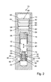
- Fig. 1 shows a schematic representation of an exemplary embodiment of a valve assembly 10 according to the invention, which may be provided for example for driving a door or a window.
- the valve assembly 10 comprises a valve body 12 having Regulierventil 14 which is arranged in a provided with an internal thread 16 receiving bore 18, for example, a drive housing and axially adjustable by rotating about its longitudinal axis L for variable adjustment of a hydraulic channel 20 associated throttle gap 22.
- the valve body 12 of the regulating valve 14 comprises a first valve body 24 serving as a rotatable actuator with an external thread 26 cooperating with the internal thread 16 of the receiving bore 18 and a second valve body 28 arranged in the region of the throttle gap 22 and serving as the control part.
- the second valve body 28 is received in the receiving bore 18 so as to be axially displaceable and non-rotationally secured and has a bore 32 provided with an internal thread 30 into which an extension 36 of the first valve body 24 provided with an external thread 34 engages.
- the thread pitch of the cooperating threads 30, 34 of the second valve body part 28 and the extension 36 of the first valve body part 24 is smaller than the thread pitch of the cooperating threads 26, 16 of the first valve body part 24 and the receiving bore 18th
- Fig. 2 How best by the Fig. 2 can be seen in which the valve assembly 10 according to Fig. 1 is reproduced after a successful rotation of the first valve body part 24, due to the difference in the thread pitches with a respective rotation of the actuator serving as the first valve body part 24 serving as the control part second valve body part 28 adjusted by a much smaller amount 38 in the axial direction, than that in the first Valve body part 24 is the case, which is adjusted by a larger amount 40.
- the regulating valve 14 can also be set much finer, for example, by hand.
- the receiving bore 18 can, as already mentioned, be provided, for example, in the housing of a drive for a door or a window, in which, for example, a piston and a spring comprising energy storage are arranged in a space filled with hydraulic fluid in a conventional manner.
- the energy storage is charged by manually or automatically opening the wing of the door or the window and causes the wing is automatically transferred after opening again in its closed position.
- the drive causes the application of force to the wing via a hinged linkage or via a sliding arm guided in a slide by means of a sliding block, which is arranged rotationally fixed on an output shaft which is operatively connected to the piston.
- the drive housing also hydraulic channels and regulating valves are arranged, by means of which an overflow of the hydraulic fluid from one piston side to the other to control the behavior of the drive is possible.
- the regulating valves for example, a closing speed, a closing delay, an opening damping and / or the like can be set.
- the regulating valves can each be arranged in a threaded bore in the drive housing, in which the valve seat of the associated hydraulic channel is formed.
- the present valve arrangement 10 according to the invention can also be used, for example, in such a door or window drive.
- the second valve body part 28 of the regulating valve 14 of the valve arrangement according to the invention can be secured against rotation in particular by a transition fit or a form fit in the receiving bore 18.
- the first valve body part 24 may include a valve head 42 which is provided with a tool holder 44 for a tool such as in particular a screwdriver or the like. About such a screwdriver, the valve can in particular be operated manually.
- the guided in the hydraulic channel 20 hydraulic fluid 46 can enter via an inlet opening 48 into the receiving bore 18 and exit, for example, via one of these inlet opening 48 opposite outlet opening 50 again from the receiving bore 18.
- the first valve body part 24 may be provided with an annular groove 52 in which a sealing ring 54 is arranged.
- the sealing ring 54 for example, be formed by an injection molding tool, not shown, that it is spaced, for example, the lower edge 56 of the groove, whereby sufficient space for elastic deflection of the sealing ring 54 is given in its deformation in the receiving bore 18.
- an annular material projection 60 may be provided on the sealing ring 54, the outer diameter of which is smaller than the inner diameter of the adjacent portion of the receiving bore 18, so that sufficient space for elastic deformation of the sealing ring in the direction of the edge 58 54 is given.
- first valve body 24 may be provided with a arranged in an annular groove 62 securing ring 64 for securing the first valve body part 24 against rotation.
- the sealing ring 54 seals the hydraulic fluid to the outside.
- the locking ring 64 is expediently arranged outside the sealed by the sealing ring 54 dry region of the receiving bore 18, so that a constant high braking effect by friction between the locking ring 64 and the wall of the receiving bore 18 is ensured.
- the sealing ring 54 contributes only slightly to an anti-rotation, since a partial wetting by hydraulic fluid is possible.
- the circlip 64 is thus arranged axially between the sealing ring 54 and the end face 66 of the first valve body part 24 which is accessible from the outside and has the tool receptacle 44.
- valve assembly 10 which serves as a control part second valve body 28 has a cylindrical shape.
- Fig. 3 shows a schematic representation of another exemplary embodiment of the valve assembly 10 according to the invention, which differs from the embodiment according to the Fig. 1 and 2 essentially only differs in that the serving as a control part second valve body part 28 is designed conical.
- this valve arrangement has 10 at least substantially the same structure as in the Fig. 1 and 2 illustrated embodiment. Corresponding parts are assigned the same reference numerals.
- Fig. 4 shows the valve assembly 10 according to Fig. 3 again after a successful rotation of the first valve body part 24. It can be seen again that the second valve body part 28 is adjusted due to the difference in the thread pitches with a respective rotation of the first valve body part 24 by a substantially smaller amount 38 in the axial direction than the first valve body part 24th , which is adjusted by the larger amount 40 in the axial direction.
Abstract
Eine Ventilanordnung (10) insbesondere für einen Antrieb einer Tür oder eines Fensters umfasst ein einen Ventilkörper (12) aufweisendes Regulierventil (14), das in einer mit einem Innengewinde (16) versehenen Aufnahmebohrung (18) angeordnet und durch Drehen um seine Längsachse (L) zur variablen Einstellung eines einem Hydraulikkanal (20) zugeordneten Drosselspaltes (22) axial verstellbar ist. Der Ventilkörper (12) des Regulierventils (14) umfasst einen als drehbares Stellglied dienenden ersten Ventilkörperteil (24) mit einem mit dem Innengewinde (16) der Aufnahmebohrung (18) zusammenwirkenden Außengewinde (26) sowie einen im Bereich des Drosselspaltes (22) angeordneten, als Steuerteil dienenden zweiten Ventilkörperteil (28), der in der Aufnahmebohrung (18) axial verschiebbar und drehgesichert ist sowie eine mit einem Innengewinde (30) versehene Bohrung (32) aufweist, in die ein mit einem Außengewinde (34) versehener Fortsatz (36) des ersten Ventilkörperteils (24) eingreift. Dabei ist die Gewindesteigung der zusammenwirkenden Gewinde (30,34) des zweiten Ventilkörperteils (28) und des Fortsatzes (36) des ersten Ventilkörperteils (24) kleiner als die Gewindesteigung der zusammenwirkenden Gewinde (26,16) des ersten Ventilkörperteils (24) und der Aufnahmebohrung (18).A valve arrangement (10), in particular for driving a door or a window, comprises a regulating valve (14) having a valve body (12) arranged in a receiving bore (18) provided with an internal thread (16) and rotated about its longitudinal axis (L ) for the variable adjustment of a hydraulic channel (20) associated throttle gap (22) is axially adjustable. The valve body (12) of the regulating valve (14) comprises a first valve body part (24) serving as a rotatable actuator with an external thread (26) cooperating with the internal thread (16) of the receiving bore (18) and one in the region of the throttle gap (22). serving as a control part second valve body part (28) which is axially displaceable and rotationally secured in the receiving bore (18) and provided with an internal thread (30) bore (32) into which an externally threaded (34) versehener extension (36) of the first valve body part (24) engages. The thread pitch of the cooperating threads (30, 34) of the second valve body part (28) and the extension (36) of the first valve body part (24) is smaller than the thread pitch of the cooperating threads (26, 16) of the first valve body part (24) and Receiving bore (18).
Description
Die vorliegende Erfindung betrifft eine Ventilanordnung insbesondere für einen Antrieb einer Tür oder eines Fensters, mit einem einen Ventilkörper umfassenden Regulierventil, das in einer mit einem Innengewinde versehenen Aufnahmebohrung angeordnet und durch Drehen um seine Längsachse zur variablen Einstellung eines einem Hydraulikkanal zugeordneten Drosselspaltes axial verstellbar ist.The present invention relates to a valve assembly, in particular for driving a door or a window, comprising a regulating valve comprising a valve body, which is arranged in a receiving bore provided with an internal thread and axially adjustable by rotating about its longitudinal axis for variable adjustment of a hydraulic gap associated throttle gap.
Antriebe für Türen oder Fenster sind an sich bekannt und können als manuelle oder automatische Antriebe ausgeführt sein. In bekannter Weise umfasst ein derartiger Antrieb ein Gehäuse mit einer Bohrung, in der ein Arbeitskolben angeordnet ist, der mit einer Abtriebswelle getriebemäßig zusammenwirkt. Auf der Abtriebswelle kann ein Gestänge oder ein Gleitarm drehfest angeordnet sein. Der Antrieb kann wahlweise an einem Flügel der Tür oder des Fensters oder an deren Umrahmung angeordnet sein. Entsprechend stützt sich das Gestänge oder der Gleitarm am Rahmen oder dem Flügel ab, wodurch eine Verbindung zwischen der Schwenkbewegung des Flügels und dem Antrieb bewirkt wird.Drives for doors or windows are known per se and can be designed as manual or automatic drives. In known manner, such a drive comprises a housing with a bore in which a working piston is arranged, which cooperates with an output shaft geared. On the output shaft, a linkage or a sliding arm can be arranged rotatably. The drive can be arranged either on a wing of the door or the window or on the framing. Accordingly, the linkage or the sliding arm is supported on the frame or the wing, whereby a connection between the pivotal movement of the wing and the drive is effected.
Im mit einer Hydraulikflüssigkeit gefüllten Gehäuse ist zudem eine Feder angeordnet, die bei einer Drehbewegung der Abtriebswelle beim manuellen oder beispielsweise durch eine Hydraulikpumpe bewirkten automatischen Öffnen des Flügels durch Verschieben des Arbeitskolbens komprimiert wird und als Energiespeicher zum selbsttätigen Schließen des Flügels dient. Der Innenraum des Gehäuses ist durch den Kolben in mehrere Räume aufgeteilt. Zwischen diesen Räumen sind Hydraulikkanäle mit zugeordneten Ventilen zur Beeinflussung des Überströmens der Hydraulikflüssigkeit angeordnet, die der Steuerung des Antriebsverhaltens dienen.In the filled with a hydraulic fluid housing, a spring is also arranged, which is compressed during a rotational movement of the output shaft when manually or for example caused by a hydraulic pump automatic opening of the wing by moving the working piston and serves as an energy storage for automatic closing of the wing. The interior of the housing is divided by the piston into several rooms. Between these spaces hydraulic channels are arranged with associated valves for influencing the overflow of the hydraulic fluid, which serve to control the drive behavior.
Die Ventile sind jeweils in einer mit einem Gewinde versehenden Bohrung im Gehäuse des Antriebs angeordnet und werden durch Drehen eingestellt, wodurch ein Abschnitt des Ventils relativ zu einem in dem Hydraulikkanal angeordneten Ventilsitz verlagert wird und so den Hydraulikkanal mehr oder weniger weit öffnet bzw. schließt.The valves are each disposed in a threaded bore in the housing of the drive and are adjusted by rotation, whereby a portion of the valve is displaced relative to a arranged in the hydraulic passage valve seat and thus more or less opens or closes the hydraulic channel.
Bei den bisher üblichen Ventilanordnungen der eingangs genannten Art, wie sie beispielsweise bei Türschließern oder dergleichen eingesetzt werden, wird der Hydraulikflüssigkeitsstrom meistens über sehr kleine Drosselspalte reguliert. Zur Einstellung des betreffenden Drosselspaltes ist der Ventilkörper der bisher bekannten Regulierventile mit einem Verstellgewinde versehen, dessen Gewindesteigung typischerweise in einem Bereich von etwa 0,5 mm bis etwa 0,75 mm je Umdrehung des Ventilkörpers liegt. Der erforderliche Stellbereich in axialer Richtung beträgt nun aber in der Regel nur einige wenige hundertstel Millimeter, so dass es sehr schwierig ist, die Ventile von Hand einzustellen.In the usual valve arrangements of the type mentioned, as used for example in door closers or the like, the hydraulic fluid flow is usually regulated by very small throttle gaps. To set the respective throttle gap of the valve body of the previously known regulating valves is provided with an adjusting thread whose thread pitch is typically in a range of about 0.5 mm to about 0.75 mm per revolution of the valve body. The required adjustment range in the axial direction is now but usually only a few hundredths of a millimeter, so that it is very difficult to adjust the valves by hand.
Der Erfindung liegt somit die Aufgabe zugrunde, eine verbesserte Ventilanordnung der eingangs genannten Art anzugeben, mit der auf möglichst einfache Weise insbesondere auch manuell eine Feineinstellung möglich ist.The invention is therefore an object of the invention to provide an improved valve assembly of the type mentioned, with the simplest possible way in particular also manually fine adjustment is possible.
Erfindungsgemäß wird diese Aufgabe durch eine Ventilanordnung mit den Merkmalen des Anspruchs 1 gelöst. Bevorzugte Ausführungsformen der erfindungsgemäßen Ventilanordnung sind in den Unteransprüchen angegeben.According to the invention, this object is achieved by a valve arrangement having the features of claim 1. Preferred embodiments of the valve arrangement according to the invention are specified in the subclaims.
Die erfindungsgemäße Ventilanordnung zeichnet sich dadurch aus, dass der Ventilkörper des Regulierventils einen als drehbares Stellglied dienenden ersten Ventilkörperteil mit einem mit dem Innengewinde der Aufnahmebohrung zusammenwirkenden Außengewinde sowie einen im Bereich des Drosselspaltes angeordneten, als Steuerteil dienenden zweiten Ventilkörperteil umfasst, der in der Aufnahmebohrung axial verschiebbar und drehgesichert ist sowie eine mit einem Innengewinde versehene Bohrung aufweist, in die ein mit einem Außengewinde versehener Fortsatz des ersten Ventilkörperteils eingreift, wobei die Gewindesteigung der zusammenwirkenden Gewinde des zweiten Ventilkörperteils und des Fortsatzes des ersten Ventilkörperteils kleiner ist als die Gewindesteigung der zusammenwirkenden Gewinde des ersten Ventilkörperteils und der Aufnahmebohrung.The valve arrangement according to the invention is characterized in that the valve body of the regulating valve comprises a first valve body part serving as a rotatable actuator with an external thread cooperating with the internal thread of the receiving bore and a second valve body part serving as a control part arranged in the region of the throttle gap and axially displaceable in the receiving bore and rotationally secured and having an internally threaded bore in which engages an externally threaded extension of the first valve body part, wherein the pitch of the cooperating threads of the second valve body part and the extension of the first valve body part is smaller than the thread pitch of the cooperating threads of the first Valve body part and the receiving bore.
Infolge der Differenz der Gewindesteigungen wird der als Steuerteil zur Ansteuerung des Drosselspaltes dienende zweite Ventilkörperteil mit einer jeweiligen Drehung des als Stellglied dienenden ersten Ventilkörperteils um einen entsprechend kleineren Betrag je Umdrehung des ersten Ventilkörperteils in axialer Richtung verstellt, womit entsprechend eine Feineinstellung ermöglicht wird. Mit der erfindungsgemäßen Ventilanordnung ist somit eine wesentlich feinere Regulierung möglich, was insbesondere dann von Vorteil ist, wenn eine manuelle Einstellung vorgenommen werden muss.As a result of the difference in the thread pitch of serving as a control part for controlling the throttle gap second valve body part is adjusted with a respective rotation of the actuator serving as a first valve body part by a correspondingly smaller amount per revolution of the first valve body part in the axial direction, thus corresponding to a Fine adjustment is possible. With the valve assembly according to the invention thus a much finer regulation is possible, which is particularly advantageous if a manual adjustment must be made.
Der zweite Ventilkörper kann insbesondere durch eine Übergangspassung oder einen Formschluss in der Aufnahmebohrung drehgesichert sein.The second valve body may be secured against rotation in particular by a transition fit or a positive connection in the receiving bore.
Gemäß einer zweckmäßigen praktischen Ausführungsform der erfindungsgemäßen Ventilanordnung umfasst der erste Ventilkörperteil einen Ventilkopf, der mit einer Werkzeugaufnahme für ein Werkzeug wie beispielsweise einen Schraubendreher oder dergleichen versehen ist. Mittels eines solchen Werkzeugs kann das Ventil dann manuell eingestellt werden, wobei aufgrund der Differenz der Gewindesteigungen insbesondere auch bei einer manuellen Betätigung eine besonders feine Einstellung ermöglicht wird.According to an expedient practical embodiment of the valve assembly according to the invention, the first valve body part comprises a valve head, which is provided with a tool holder for a tool such as a screwdriver or the like. By means of such a tool, the valve can then be adjusted manually, with a particularly fine adjustment is possible due to the difference in the thread pitches, especially in a manual operation.
Die Ventilanordnung kann beispielsweise so ausgeführt sein, dass die im Hydraulikkanal geführte Hydraulikflüssigkeit über eine Eintrittsöffnung in die Aufnahmebohrung eintritt und über eine dieser Eintrittsöffnung gegenüberliegende Austrittsöffnung wieder aus der Aufnahmebohrung austritt.The valve arrangement can be designed, for example, such that the hydraulic fluid guided in the hydraulic channel enters the receiving bore via an inlet opening and exits the receiving bore again via an outlet opening lying opposite this inlet opening.
Der als Steuerteil zur Ansteuerung des Drosselspaltes dienende zweite Ventilkörperteil kann insbesondere eine zylindrische Form besitzen oder beispielsweise auch kegelförmig ausgeführt sein.The serving as a control part for controlling the throttle gap second valve body part may in particular have a cylindrical shape or be designed, for example, conical.
Bevorzugt ist der erste Ventilkörperteil mit einer ringförmigen Nut versehen, in der ein Dichtring angeordnet ist.Preferably, the first valve body part is provided with an annular groove in which a sealing ring is arranged.
Dabei kann der Dichtring beispielsweise durch ein Spritzgusswerkzeug so ausgeformt sein, dass er zumindest zu einer Flanke der ringförmigen Nut in einem Abstand angeordnet ist, so dass ausreichend Raum für ein elastisches Ausweichen des Dichtrings bei dessen Verformung in der Aufnahmebohrung gegeben ist. Zur anderen Flanke der Nut hin kann am Dichtring beispielsweise ein ringförmiger Materialansatz vorgesehen sein, durch den der im montierten Zustand an der Wandung der Aufnahmebohrung anliegende dichtende Bereich des Dichtrings in einem Abstand zu dieser Flanke positioniert ist. Dabei kann der Materialansatz insbesondere einen geringeren Durchmesser als der Dichtring aufweisen und gegenüber der betreffenden Flanke radial zurückgesetzt sein, so dass auch in Richtung dieser Flanke ausreichend Raum für eine elastische Verformung des Dichtrings vorhanden ist.In this case, the sealing ring may be formed, for example, by an injection molding tool so that it is arranged at least at an edge of the annular groove at a distance, so that sufficient space for an elastic deflection of the sealing ring is given in its deformation in the receiving bore. On the other flank of the groove can be provided on the sealing ring, for example, an annular material approach which is positioned in the mounted state against the wall of the receiving bore sealing region of the sealing ring at a distance from this edge. In this case, the material approach may in particular have a smaller diameter than the sealing ring and be set back radially relative to the relevant edge, so that there is sufficient space for elastic deformation of the sealing ring in the direction of this edge.
Von Vorteil ist insbesondere auch, wenn der erste Ventilkörperteil mit einem in einer ringförmigen Nut angeordneten Sicherungsring zur Sicherung des ersten Ventilkörperteils gegen Verdrehen versehen ist. Dadurch ein ungewolltes Verstellen des Ventils verhindert.It is particularly advantageous if the first valve body part is provided with a arranged in an annular groove retaining ring for securing the first valve body part against rotation. This prevents accidental adjustment of the valve.
Dabei ist dieser Sicherungsring bevorzugt axial zwischen dem Dichtring und der von außen zugänglichen Stirnseite des Ventilkörperteils angeordnet. Damit dichtet der Dichtring die Hydraulikflüssigkeit nach außen hin ab, während der Sicherungsring weiter außen im abgedichteten trockenen Bereich der Aufnahmebohrung liegt, wodurch eine gleichbleibend hohe Bremswirkung durch Reibung zwischen dem Sicherungsring und der Wandung der Aufnahmebohrung erzielt wird.In this case, this retaining ring is preferably arranged axially between the sealing ring and the externally accessible end face of the valve body part. Thus, the sealing ring seals the hydraulic fluid to the outside, while the retaining ring is located further out in the sealed dry area of the receiving bore, whereby a consistently high braking effect is achieved by friction between the retaining ring and the wall of the receiving bore.
Die Erfindung wird im Folgenden anhand von Ausführungsbeispielen unter Bezugnahme auf die Zeichnung näher erläutert; in dieser zeigen:
- Fig. 1
- eine schematische Darstellung einer beispielhaften Ausführungsform einer erfindungsgemäßen Ventilanordnung,
- Fig. 2
- eine schematische Darstellung der Ventilanordnung gemäß
Fig. 1 nach einem erfolgten Verdrehen des ersten Ventilkörperteils, - Fig. 3
- eine schematische Darstellung einer weiteren beispielhaften Ausführungsform der erfindungsgemäßen Ventilanordnung, und
- Fig. 4
- eine schematische Darstellung der Ventilanordnung gemäß
Fig. 3 nach einem erfolgten Verdrehen des ersten Ventilkörperteils.
- Fig. 1
- a schematic representation of an exemplary embodiment of a valve assembly according to the invention,
- Fig. 2
- a schematic representation of the valve assembly according to
Fig. 1 after a successful rotation of the first valve body part, - Fig. 3
- a schematic representation of another exemplary embodiment of the valve assembly according to the invention, and
- Fig. 4
- a schematic representation of the valve assembly according to
Fig. 3 after a successful rotation of the first valve body part.
Die Ventilanordnung 10 umfasst ein einen Ventilkörper 12 aufweisendes Regulierventil 14, das in einer mit einem Innengewinde 16 versehenen Aufnahmebohrung 18 beispielsweise eines Antriebsgehäuses angeordnet und durch Drehen um seine Längsachse L zur variablen Einstellung eines einem Hydraulikkanal 20 zugeordneten Drosselspaltes 22 axial verstellbar ist.The
Der Ventilkörper 12 des Regulierventils 14 umfasst einen als drehbares Stellglied dienenden ersten Ventilkörper 24 mit einem mit dem Innengewinde 16 der Aufnahmebohrung 18 zusammenwirkenden Außengewinde 26 sowie einen im Bereich des Drosselspaltes 22 angeordneten, als Steuerteil dienenden zweiten Ventilkörper 28.The
Der zweite Ventilkörper 28 ist in der Aufnahmebohrung 18 axial verschiebbar und drehgesichert aufgenommen und weist eine mit einem Innengewinde 30 versehene Bohrung 32 auf, in die ein mit einem Außengewinde 34 versehener Fortsatz 36 des ersten Ventilkörpers 24 eingreift. Dabei ist die Gewindesteigung der zusammenwirkenden Gewinde 30, 34 des zweiten Ventilkörperteils 28 und des Fortsatzes 36 des ersten Ventilkörperteils 24 kleiner als die Gewindesteigung der zusammenwirkenden Gewinde 26, 16 des ersten Ventilkörperteils 24 und der Aufnahmebohrung 18.The
Wie am besten anhand der
Die Aufnahmebohrung 18 kann, wie bereits erwähnt, beispielsweise im Gehäuse eines Antriebs für eine Tür oder ein Fenster vorgesehen sein, in dem in an sich bekannter Weise beispielsweise ein Kolben und ein eine Feder umfassender Energiespeicher in einem mit Hydraulikflüssigkeit gefüllten Raum angeordnet sind. In einem solchen Fall wird der Energiespeicher durch manuelles oder automatisches Öffnen des Flügels der Tür bzw. des Fensters aufgeladen und bewirkt, dass der Flügel nach dem Öffnen wieder selbsttätig in seine geschlossene Lage überführt wird. Der Antrieb bewirkt die Krafteinleitung auf den Flügel über ein gelenkig verbundenes Gestänge oder über einen in einer Gleitschiene mittels eines Gleitsteins geführten Gleitarm, das bzw. der an einer Abtriebswelle, die mit dem Kolben wirkmäßig verbunden ist, drehfest angeordnet ist. Im Antriebsgehäuse sind zudem Hydraulikkanäle und Regulierventile angeordnet, mittels derer ein Überströmen der Hydraulikflüssigkeit von einer Kolbenseite zur anderen zur Steuerung des Verhaltens des Antriebs möglich ist. Mittels der Regulierventile ist beispielsweise eine Schließgeschwindigkeit, eine Schließverzögerung, eine Öffnungsdämpfung und/oder dergleichen einstellbar. Dabei können die Regulierventile jeweils in einer mit einem Gewinde versehenen Bohrung im Antriebsgehäuse angeordnet sein, in der auch der Ventilsitz des zugeordneten Hydraulikkanals ausgebildet ist.The
Auch die vorliegende erfindungsgemäße Ventilanordnung 10 ist beispielsweise bei einem derartigen Tür- oder Fensterantrieb einsetzbar.The
Der zweite Ventilkörperteil 28 des Regulierventils 14 der erfindungsgemäßen Ventilanordnung kann insbesondere durch eine Übergangspassung oder einen Formschluss in der Aufnahmebohrung 18 drehgesichert sein.The second
Wie anhand der
Die im Hydraulikkanal 20 geführte Hydraulikflüssigkeit 46 kann über eine Eintrittsöffnung 48 in die Aufnahmebohrung 18 eintreten und beispielsweise über eine dieser Eintrittsöffnung 48 gegenüberliegende Austrittsöffnung 50 wieder aus der Aufnahmebohrung 18 austreten.The guided in the
Wie der
Zudem kann der erste Ventilkörper 24 mit einem in einer ringförmigen Nut 62 angeordneten Sicherungsring 64 zur Sicherung des ersten Ventilkörperteils 24 gegen Verdrehen versehen sein.In addition, the
Der Dichtring 54 dichtet die Hydraulikflüssigkeit nach außen hin ab. Der Sicherungsring 64 ist wie dargestellt zweckmäßigerweise außerhalb des durch den Dichtring 54 abgedichteten trockenen Bereichs der Aufnahmebohrung 18 angeordnet, so dass eine gleichbleibende hohe Bremswirkung durch Reibung zwischen dem Sicherungsring 64 und der Wandung der Aufnahmebohrung 18 gewährleistet ist. Demgegenüber trägt der Dichtungsring 54 nur gering zu einer Verdrehsicherung bei, da eine teilweise Benetzung durch Hydraulikflüssigkeit möglich ist. Der Sicherungsring 64 ist im vorliegenden Fall also axial zwischen dem Dichtring 54 und der von außen zugänglichen, die Werkzeugaufnahme 44 aufweisenden Stirnseite 66 des ersten Ventilkörperteils 24 angeordnet.The sealing
Bei der vorliegenden, in den
- 1010
- Ventilanordnungvalve assembly
- 1212
- Ventilkörpervalve body
- 1414
- Regulierventilregulating
- 1616
- Innengewindeinner thread
- 1818
- Aufnahmebohrunglocation hole
- 2020
- Hydraulikkanalhydraulic channel
- 2222
- Drosselspaltthrottle gap
- 2424
- erster Ventilkörperteilfirst valve body part
- 2626
- Außengewindeexternal thread
- 2828
- zweiter Ventilkörperteilsecond valve body part
- 3030
- Innengewindeinner thread
- 3232
- Bohrungdrilling
- 3434
- Außengewindeexternal thread
- 3636
- Fortsatzextension
- 3838
- Betragamount
- 4040
- Betragamount
- 4242
- Ventilkopfvalve head
- 4444
- Werkzeugaufnahmetool holder
- 4646
- Hydraulikflüssigkeithydraulic fluid
- 4848
- Eintrittsöffnunginlet opening
- 5050
- Austrittsöffnungoutlet opening
- 5252
- ringförmige Nutannular groove
- 5454
- Dichtringseal
- 5656
- untere Flankelower flank
- 5858
- obere Flankeupper flank
- 6060
- ringförmiger Materialansatzannular material approach
- 6262
- ringförmige Nutannular groove
- 6464
- Sicherungsringcirclip
- 6666
- Stirnseitefront
- LL
- Längsachselongitudinal axis
Claims (10)
dadurch gekennzeichnet , dass der Ventilkörper (12) des Regulierventils (14) einen als drehbares Stellglied dienenden ersten Ventilkörperteil (24) mit einem mit dem Innengewinde (16) der Aufnahmebohrung (18) zusammenwirkenden Außengewinde (26) sowie einen im Bereich des Drosselspaltes (22) angeordneten, als Steuerteil dienenden zweiten Ventilkörperteil (28) umfasst, der in der Aufnahmebohrung (18) axial verschiebbar und drehgesichert ist sowie eine mit einem Innengewinde (30) versehene Bohrung (32) aufweist, in die ein mit einem Außengewinde (34) versehener Fortsatz (36) des ersten Ventilkörperteils (24) eingreift, wobei die Gewindesteigung der zusammenwirkenden Gewinde (30, 34) des zweiten Ventilkörperteils (28) und des Fortsatzes (36) des ersten Ventilkörperteils (24) kleiner ist als die Gewindesteigung der zusammenwirkenden Gewinde (26, 16) des ersten Ventilkörperteils (24) und der Aufnahmebohrung (18).Valve arrangement (10) in particular for driving a door or a window, comprising a regulating valve (14) comprising a valve body (12) arranged in a receiving bore (18) provided with an internal thread (16) and rotating about its longitudinal axis (L ) is axially adjustable for the variable adjustment of a hydraulic gap (20) associated throttle gap (22),
characterized in that the valve body (12) of the regulating valve (14) serves as a rotatable actuator first valve body part (24) with a with the internal thread (16) of the receiving bore (18) cooperating external thread (26) and in the region of the throttle gap (22 ), which serves as a control part second valve body part (28) which is axially displaceable and rotationally secured in the receiving bore (18) and provided with an internal thread (30) bore (32) into which a with an external thread (34) versehener Extension (36) of the first valve body part (24) engages, wherein the thread pitch of the cooperating threads (30, 34) of the second valve body part (28) and the extension (36) of the first valve body part (24) is smaller than the thread pitch of the cooperating threads (24). 26, 16) of the first valve body part (24) and the receiving bore (18).
dadurch gekennzeichnet, dass der zweite Ventilkörperteil (28) durch eine Übergangspassung oder einen Formschluss in der Aufnahmebohrung (18) drehgesichert ist.Valve arrangement according to claim 1,
characterized in that the second valve body part (28) is secured against rotation by a transition fit or a form fit in the receiving bore (18).
dadurch gekennzeichnet, dass der erste Ventilkörperteil (24) einen Ventilkopf (42) umfasst, der mit einer Werkzeugaufnahme (44) für ein Werkzeug versehen ist.Valve arrangement according to claim 1 or 2,
characterized in that the first valve body part (24) comprises a valve head (42) provided with a tool holder (44) for a tool.
dadurch gekennzeichnet, dass die im Hydraulikkanal (20) geführte Hydraulikflüssigkeit (46) über eine Eintrittsöffnung (48) in die Aufnahmebohrung (18) eintritt und über eine dieser Eintrittsöffnung (48) gegenüberliegende Austrittsöffnung (50) wieder aus der Aufnahmebohrung (18) austritt.Valve arrangement according to at least one of the preceding claims,
characterized in that in the hydraulic channel (20) guided hydraulic fluid (46) via an inlet opening (48) enters the receiving bore (18) and via one of these inlet opening (48) opposite the outlet opening (50) again from the receiving bore (18) emerges.
dadurch gekennzeichnet, dass der zweite Ventilkörperteil (28) eine zylindrische Form besitzt.Valve arrangement according to at least one of the preceding claims,
characterized in that the second valve body part (28) has a cylindrical shape.
dadurch gekennzeichnet, dass der zweite Ventilkörperteil (28) kegelförmig ausgeführt ist.Valve arrangement according to one of claims 1 to 4,
characterized in that the second valve body part (28) is designed conical.
dadurch gekennzeichnet, dass der erste Ventilkörperteil (24) mit einer ringförmigen Nut (52) versehen ist, in der ein Dichtring (54) angeordnet ist.Valve arrangement according to at least one of the preceding claims,
characterized in that the first valve body part (24) is provided with an annular groove (52) in which a sealing ring (54) is arranged.
dadurch gekennzeichnet, dass der Dichtring (54) in einem Abstand zu einer Flanke (56) der ringförmigen Nut (52) angeordnet ist.Valve arrangement according to claim 7,
characterized in that the sealing ring (54) is arranged at a distance from a flank (56) of the annular groove (52).
dadurch gekennzeichnet, dass der erste Ventilkörperteil (24) mit einem in einer ringförmigen Nut (62) angeordneten Sicherungsring (64) zur Sicherung des ersten Ventilkörperteils (24) gegen Verdrehen versehen ist.Valve arrangement according to at least one of the preceding claims,
characterized in that the first valve body part (24) is provided with a in an annular groove (62) arranged securing ring (64) for securing the first valve body part (24) against rotation.
dadurch gekennzeichnet , dass der Sicherungsring (64) axial zwischen dem Dichtring (54) und der von außen zugänglichen Stirnseite (66) des ersten Ventilkörperteils (24) angeordnet ist.Valve arrangement according to claim 9,
characterized in that the securing ring (64) is arranged axially between the sealing ring (54) and the externally accessible end face (66) of the first valve body part (24).
Applications Claiming Priority (1)
| Application Number | Priority Date | Filing Date | Title |
|---|---|---|---|
| DE102014212065.9A DE102014212065A1 (en) | 2014-06-24 | 2014-06-24 | valve assembly |
Publications (1)
| Publication Number | Publication Date |
|---|---|
| EP2960562A1 true EP2960562A1 (en) | 2015-12-30 |
Family
ID=53488204
Family Applications (1)
| Application Number | Title | Priority Date | Filing Date |
|---|---|---|---|
| EP15173237.7A Withdrawn EP2960562A1 (en) | 2014-06-24 | 2015-06-23 | Valve assembly |
Country Status (3)
| Country | Link |
|---|---|
| EP (1) | EP2960562A1 (en) |
| CN (1) | CN105317305A (en) |
| DE (1) | DE102014212065A1 (en) |
Cited By (1)
| Publication number | Priority date | Publication date | Assignee | Title |
|---|---|---|---|---|
| IT201800006596A1 (en) * | 2018-06-22 | 2019-12-22 | BALANCING VALVE FOR A HYDRAULIC CIRCUIT AND A HYDRAULIC AND / OR HYDROTHERMAL CIRCUIT INCLUDING THIS BALANCING VALVE |
Families Citing this family (2)
| Publication number | Priority date | Publication date | Assignee | Title |
|---|---|---|---|---|
| DE102018210296B4 (en) * | 2018-06-25 | 2020-04-09 | Geze Gmbh | Drive for a door or window sash |
| CN112177462B (en) * | 2019-07-04 | 2022-05-31 | 陈旺松 | Combined hinge and hydraulic device |
Citations (4)
| Publication number | Priority date | Publication date | Assignee | Title |
|---|---|---|---|---|
| FR805910A (en) * | 1935-05-13 | 1936-12-03 | Const D App A Gaz S A | Needle valve |
| FR2593260A1 (en) * | 1986-01-17 | 1987-07-24 | Filleau Paul | Tap controlled by a micrometric screw |
| WO2004003412A1 (en) * | 2002-06-27 | 2004-01-08 | Dorma Gmbh + Co. Kg | Slide valve |
| DE202007004104U1 (en) * | 2007-03-16 | 2007-05-24 | Dorma Gmbh + Co. Kg | Regulating valve for hydraulic door closer has anti-rotation lock on body formed by groove on thread and holding elastic element to eliminate play |
Family Cites Families (4)
| Publication number | Priority date | Publication date | Assignee | Title |
|---|---|---|---|---|
| FI102556B (en) * | 1997-07-04 | 1998-12-31 | Abloy Oy | Adjusting device for door closer |
| GB9724968D0 (en) * | 1997-11-27 | 1998-01-28 | Newman Tonks Group Plc | Improvements in or relating to valves |
| DE202007009174U1 (en) * | 2007-06-29 | 2007-08-30 | Dorma Gmbh + Co. Kg | regulating |
| DE202007009175U1 (en) * | 2007-06-29 | 2007-08-30 | Dorma Gmbh + Co. Kg | Flow control valve for use in borehole of hydraulic door closer, has inserted part lockably cooperated with borehole or internal thread of door closer, where outer diameter of part has larger diameter than borehole or internal thread |
-
2014
- 2014-06-24 DE DE102014212065.9A patent/DE102014212065A1/en not_active Withdrawn
-
2015
- 2015-06-23 EP EP15173237.7A patent/EP2960562A1/en not_active Withdrawn
- 2015-06-24 CN CN201510579962.1A patent/CN105317305A/en active Pending
Patent Citations (4)
| Publication number | Priority date | Publication date | Assignee | Title |
|---|---|---|---|---|
| FR805910A (en) * | 1935-05-13 | 1936-12-03 | Const D App A Gaz S A | Needle valve |
| FR2593260A1 (en) * | 1986-01-17 | 1987-07-24 | Filleau Paul | Tap controlled by a micrometric screw |
| WO2004003412A1 (en) * | 2002-06-27 | 2004-01-08 | Dorma Gmbh + Co. Kg | Slide valve |
| DE202007004104U1 (en) * | 2007-03-16 | 2007-05-24 | Dorma Gmbh + Co. Kg | Regulating valve for hydraulic door closer has anti-rotation lock on body formed by groove on thread and holding elastic element to eliminate play |
Cited By (1)
| Publication number | Priority date | Publication date | Assignee | Title |
|---|---|---|---|---|
| IT201800006596A1 (en) * | 2018-06-22 | 2019-12-22 | BALANCING VALVE FOR A HYDRAULIC CIRCUIT AND A HYDRAULIC AND / OR HYDROTHERMAL CIRCUIT INCLUDING THIS BALANCING VALVE |
Also Published As
| Publication number | Publication date |
|---|---|
| DE102014212065A1 (en) | 2015-12-24 |
| CN105317305A (en) | 2016-02-10 |
Similar Documents
| Publication | Publication Date | Title |
|---|---|---|
| DE60207816T2 (en) | DOOR CLOSER | |
| WO2019025568A1 (en) | Fluid damper for bodies that are movable relative to one another, comprising a piston that is movably guided in a cylinder. | |
| EP2960562A1 (en) | Valve assembly | |
| EP2518252A2 (en) | Door closer | |
| EP2730822B1 (en) | Control valve for the regulation of a hydraulic volume flow | |
| DE102014222210B3 (en) | Drive for a door or a window | |
| EP3243990A1 (en) | Drive for a door | |
| WO2015132254A1 (en) | Piston cylinder unit and door hinge with a piston cylinder unit | |
| EP2546442A1 (en) | Door hinge with damper | |
| DE10261224B3 (en) | Electrohydraulic door operating drive with open holding function provided by hydraulically-controlled valve with 2/2-way valve and non-return valve | |
| EP2458124B1 (en) | Valve for a drive to operate a door or window | |
| DE102014203879B4 (en) | Piston-cylinder unit and door hinge | |
| DE102007059707B4 (en) | Door closer housing with inclined valve | |
| EP2960417B1 (en) | Door closer | |
| DE102018210296B4 (en) | Drive for a door or window sash | |
| DE102014212110B4 (en) | regulating | |
| DE19524777B4 (en) | Door closer with adjustable preload of a closer spring | |
| EP2924216B1 (en) | Door closer | |
| EP3260641A1 (en) | Device for holding a door or a window leaf open | |
| DE102013010239B4 (en) | Valve device for abrasive fluids and/or fluidizable powder materials | |
| DE102016218090B4 (en) | VALVE ARRANGEMENT | |
| DE102018210290B4 (en) | Drive for a door or window sash | |
| DE102014222207B4 (en) | Drive for a door or a window | |
| DE202014002529U1 (en) | door closers | |
| EP2540944A2 (en) | Drive to operate the leaf of a door or the like |
Legal Events
| Date | Code | Title | Description |
|---|---|---|---|
| PUAI | Public reference made under article 153(3) epc to a published international application that has entered the european phase |
Free format text: ORIGINAL CODE: 0009012 |
|
| AK | Designated contracting states |
Kind code of ref document: A1 Designated state(s): AL AT BE BG CH CY CZ DE DK EE ES FI FR GB GR HR HU IE IS IT LI LT LU LV MC MK MT NL NO PL PT RO RS SE SI SK SM TR |
|
| AX | Request for extension of the european patent |
Extension state: BA ME |
|
| STAA | Information on the status of an ep patent application or granted ep patent |
Free format text: STATUS: THE APPLICATION HAS BEEN WITHDRAWN |
|
| 18W | Application withdrawn |
Effective date: 20160628 |