EP2960104A1 - Verfahren und System zur Einstellung des relativen vertikalen Abstandes zwischen einem Fahrzeugsitz und mindestens einer weiteren Fahrzeugkomponente - Google Patents
Verfahren und System zur Einstellung des relativen vertikalen Abstandes zwischen einem Fahrzeugsitz und mindestens einer weiteren Fahrzeugkomponente Download PDFInfo
- Publication number
- EP2960104A1 EP2960104A1 EP14173885.6A EP14173885A EP2960104A1 EP 2960104 A1 EP2960104 A1 EP 2960104A1 EP 14173885 A EP14173885 A EP 14173885A EP 2960104 A1 EP2960104 A1 EP 2960104A1
- Authority
- EP
- European Patent Office
- Prior art keywords
- vehicle
- driver
- vertical distance
- input data
- setting
- Prior art date
- Legal status (The legal status is an assumption and is not a legal conclusion. Google has not performed a legal analysis and makes no representation as to the accuracy of the status listed.)
- Granted
Links
- 238000000034 method Methods 0.000 title claims abstract description 27
- 230000007423 decrease Effects 0.000 claims abstract description 12
- 238000004590 computer program Methods 0.000 claims 2
- 210000003128 head Anatomy 0.000 description 10
- 238000005516 engineering process Methods 0.000 description 4
- 230000000694 effects Effects 0.000 description 2
- 230000037396 body weight Effects 0.000 description 1
- 230000006835 compression Effects 0.000 description 1
- 238000007906 compression Methods 0.000 description 1
- 238000010276 construction Methods 0.000 description 1
- 230000001419 dependent effect Effects 0.000 description 1
- 230000003203 everyday effect Effects 0.000 description 1
- 238000010191 image analysis Methods 0.000 description 1
- 238000012986 modification Methods 0.000 description 1
- 230000004048 modification Effects 0.000 description 1
- 238000012544 monitoring process Methods 0.000 description 1
- 230000000007 visual effect Effects 0.000 description 1
Images

Classifications
-
- B—PERFORMING OPERATIONS; TRANSPORTING
- B60—VEHICLES IN GENERAL
- B60N—SEATS SPECIALLY ADAPTED FOR VEHICLES; VEHICLE PASSENGER ACCOMMODATION NOT OTHERWISE PROVIDED FOR
- B60N2/00—Seats specially adapted for vehicles; Arrangement or mounting of seats in vehicles
- B60N2/02—Seats specially adapted for vehicles; Arrangement or mounting of seats in vehicles the seat or part thereof being movable, e.g. adjustable
- B60N2/0224—Non-manual adjustments, e.g. with electrical operation
- B60N2/0244—Non-manual adjustments, e.g. with electrical operation with logic circuits
- B60N2/0268—Non-manual adjustments, e.g. with electrical operation with logic circuits using sensors or detectors for adapting the seat or seat part, e.g. to the position of an occupant
-
- B—PERFORMING OPERATIONS; TRANSPORTING
- B60—VEHICLES IN GENERAL
- B60N—SEATS SPECIALLY ADAPTED FOR VEHICLES; VEHICLE PASSENGER ACCOMMODATION NOT OTHERWISE PROVIDED FOR
- B60N2/00—Seats specially adapted for vehicles; Arrangement or mounting of seats in vehicles
- B60N2/02—Seats specially adapted for vehicles; Arrangement or mounting of seats in vehicles the seat or part thereof being movable, e.g. adjustable
- B60N2/04—Seats specially adapted for vehicles; Arrangement or mounting of seats in vehicles the seat or part thereof being movable, e.g. adjustable the whole seat being movable
- B60N2/16—Seats specially adapted for vehicles; Arrangement or mounting of seats in vehicles the seat or part thereof being movable, e.g. adjustable the whole seat being movable height-adjustable
Definitions
- the invention relates to a method for setting the relative vertical distance between a vehicle seat and at least a further vehicle component in a vehicle, said method comprising: providing input data related to the vertical position of a driver of said vehicle; and setting said vertical distance based on said input data.
- the invention also relates to a system for setting the relative vertical distance between a vehicle seat and at least a further vehicle component in a vehicle, said system comprising a control unit configured for providing input data related to the vertical position of a driver of said vehicle and for setting said vertical distance based on said input data,
- the driver needs a clear and unobstructed view of the surrounding traffic situation and also of the vehicle's instrument panel. Also, the driver needs a clear view of the vehicle's rear view mirrors, i.e. both the internal rear view mirror and the external rear view mirrors.
- the patent document DE 19519619 discloses a system which is arranged for automatically adjusting the rear view mirrors of a vehicle. More precisely, the rear view mirrors are fitted with adjusting servo motors which are controlled by a processor. Furthermore, sensors in front of the position of the driver of the vehicle are configured to monitor the position of a driver's head and automatically set the programmed optimum setting for the interior rear view mirror and the two external mirrors.
- the document US 4689537 discloses a driving position control system for a vehicle which may store user settings for different drivers in a memory.
- the system comprises a power seat having adjusting means responsive to a control signal from a control unit for adjusting the position of the seat, and detecting means for detecting the seating position of the seat and supplying a position signal to the control unit. The system may then adjust the seating position together with the angle of the mirror to an optimal position.
- an object of the invention is to provide a method which solves the above-mentioned problems related to prior art and provides a solution which is more accurate than previously known technology in order to set the relative vertical distance between different vehicle components, so as to provide an optimal seating position for the driver.
- the object is achieved by a method for setting the relative vertical distance between a vehicle seat and at least a further vehicle component in a vehicle, said method comprising: providing input data related to the vertical position of a driver of said vehicle; and setting said vertical distance based on said input data. Furthermore, the method comprises: providing said input data based on information related to natural length changes of said driver of the vehicle due to human spine length decrease during daytime; and adjusting said vertical distance at least partly based on said input data.
- the invention provides certain advantages over previously known technology, primarily due to the fact that it caters for naturally occurring length changes in the human spine during the course of a day. This means that the actual length of the driver will decrease slightly during a day, i.e after a night's sleep and rest. In this way, more accurate adjustments of the vertical position between the seat and a further vehicle component, for example a rear view mirror, can be obtained by means of the invention.
- the invention provides an advantage since the driver of a vehicle will not have to make any small adjustments of a rear view mirror, which otherwise would have to be made.
- the method further comprises setting said vertical distance by adjusting the vertical position of the vehicle seat. This means that the position of the vehicle seat is vertically adjusted, suitably by means of a control unit, in order to compensate for the natural length changes of the driver.
- the method comprises setting the vertical distance by adjusting the vertical position of a rear view mirror in said vehicle. This means that the vertical distance between the seat and the rear view mirror can be adjusted by vertical adjustment of the position of the rear view mirror. This can also be implemented in combination with vertical adjustments of the vehicle seat.
- the method comprises a step of providing said input data based on information related to natural length changes of said driver of the vehicle based on a manual setting which can be entered by said driver.
- the method comprises a step of providing said manual setting in the form of information which relates to a correct relative vertical distance as entered by the driver in the morning and in the evening, respectively.
- the method comprises providing said input data based on information related to natural length changes of said driver of the vehicle based on an input signal provided by a image capturing device in said vehicle. This means that the position of the driver in the seat can be detected by means of a camera in an automatic manner.
- a system for setting the relative vertical distance between a vehicle seat and at least a further vehicle component in a vehicle comprising a control unit configured for providing input data related to the vertical position of a driver of said vehicle and for setting said vertical distance based on said input data. Furthermore, the control unit is configured for providing said input data based on information related to natural length changes of said driver of the vehicle due to human spine decrease during daytime; and for adjusting said vertical distance at least partly based on said input.
- the invention can be applied in different types of vehicles, such as cars, trucks, buses and construction equipment. Although the invention will be described with respect to an application in the form of a car, the invention is not restricted to this particular type of vehicle, but may be used in other vehicles.
- a vehicle in the form of a car 1 in which a driver 2 is seated in a vehicle seat 3 in a conventional manner.
- the vehicle seat 3 comprises a seat cushion 3a and a backrest 3b.
- the vertical position of the vehicle seat 3 can be adjusted, as schematically indicated by means of an arrow 4 in Fig. 1 .
- the vehicle seat 3 is supported and adjustable by means of a motorized seat adjustment unit 5.
- the seat adjustment unit 5 is also arranged for setting the inclination of the backrest 3b. In this manner, it is possible to adjust the height of the seat cushion 3a and also to pivot the seat backrest 3b.
- the settings are suitably determined by means of an actuator (not shown in Fig. 1 ) of conventional type by means of which the driver 2 may provide input to a computer-based control unit 6 in order to set the desired position of the vehicle seat 3.
- the control unit 6 is then configured for controlling various motorized units (now shown) in order to adjust the vehicle seat 3 as desired by the driver 2.
- a seat adjustment unit 5 can be adapted for adjusting the position of the seat cushion 3a and backrest 3b based on manual input from a passenger or driver of a vehicle is known as such, and for this reason it is not described in further detail.
- the settings of the vehicle seat 3, as implemented by means of the seat adjustment unit 5, can be controlled in an automatic manner by means of the control unit 6.
- Such settings are based on input related to the vertical position of a driver 2. This will be described in greater detail below.
- the car 1 is furthermore provided with an additional component in the form of a rear view mirror 7 which is necessary for the driver 2 in order to assist with a clear view of the surrounding traffic.
- a rear view mirror 7 which is necessary for the driver 2 in order to assist with a clear view of the surrounding traffic.
- the car 1 may also be equipped with conventional external rear view mirrors positioned on the exterior of the car 1.
- An essential purpose with the settings of the vehicle seat 3 is to ensure that the driver 2 has a vertical position which is appropriate considering the fact that the driver's 2 head should be on a suitable level with reference to the height and position of a rear view mirror 7.
- the rear view mirror 7 can be fixedly arranged in the vehicle 7, i.e. having a fixed vertical position.
- the invention is based on the insight that the length of the human spine decreases during daytime, i.e. after a night's sleep. This is due to the load which is imposed on the spine during daytime, as opposed to a corresponding situation during sleep at night when the person in question is lying down and rests.
- the main reason for the decrease in length of the spine during daytime is at that the spinal discs of the spine are compressed when a person stands and walks. In other words, it is the body weight of the person which compresses the spinal discs and decreases the length of the spine during daytime.
- the spine of the driver 2 is indicated by means of reference numeral 8 in Fig. 1 .
- the spine 8 extends from a lower end point 8a, which generally corresponds to the position of the so-called sacrum and up to a point close to the head of the driver 2.
- a distance d 1 which extends from said lower end point 8a of the spine and up to the vertical position of the driver's 2 eyes 9.
- the distance d 1 as shown in Fig. 1 corresponds to a situation in the morning, i.e. when the spine 8 has been relieved from compressive forces during sleep. Consequently, the length of the spine 8 has its maximum value, which means that the distance d 1 is relatively long.
- the distance d 2 as shown in Fig. 1 corresponds to a situation in the evening, i.e. after a day of walking and standing up, meaning that compressive forces cause the spine 8 to be compressed slightly. This means that the distance d 2 is slightly shorter than the distance d 1 .
- the difference between d 1 and d 2 is normally in the magnitude of 10 mm for an adult person of average length.
- the invention is based on the principle that there is provided an adjustment of the relative vertical distance between the vehicle seat 3 and the rear view mirror 7 in order in order to compensate for the difference in length of the spine 8 between the morning and the evening.
- Fig. 1 indicates in a schematic manner the effect of this change of the length of the spine 8, i.e. the length as measured from the lower end point 8a to the end of the spine 8 close to the head of the driver 2 decreases during the course of a day.
- the embodiment in Fig. 1 can be configured so that the driver may operate an actuator (not shown) in the vehicle 1, for example in the form of a push button or similar, which upon actuation saves the settings of the seat 3.
- an actuator not shown
- Such a saving process can be carried out once in the morning and once in the evening and should correspond to optimal seat positions for the driver 2 on both occassions, i.e. it should correspond to morning and evening positions wherein the driver 2 has an optimal position with a clear and correct view of the surrounding traffic situation and of the vehicle's instrument panel.
- the control unit 6 is configured for automatically adjusting the relative vertical distance between the seat 3 and the rear view mirror 7 during a day, based on the driver's 2 morning and evening settings, in order to avoid further manual adjustments. These automatic adjustments are carried out by means of the control unit 6 issuing adjustment instructions to the seat adjustment unit 5 which is associated with the seat 3.
- the invention as described with reference to Fig. 1 is arranged for setting the relative vertical distance between the seat 3 and the rear view mirror 7 and is arranged for providing input data related to the vertical position of a driver 2 and for setting the vertical distance based on said input data. Furthermore, the input data is based on information related to natural length changes of the driver due to human spine decrease during daytime. Adjustments of the vertical distance can then be based on said input data so that the position of the seat 3 is slightly adjusted during the day, either step by step or continuously.
- FIG. 2 An alternative embodiment of the invention is shown in Fig. 2 .
- This embodiment generally corresponds to the embodiment shown in Fig. 1 but, in contrast to Fig. 1 , it shows an embodiment in which the rear view mirror 7 does not have a fixed vertical position but can be adjusted vertically.
- the embodiment includes a mirror adjustment unit 10 which is arranged for setting the vertical height of the rear view mirror 7, i.e. for adjusting the rear view mirror 7 in the vertical direction.
- the mirror adjustment unit 10 is connected to the control unit 6 and is also configured for receiving commands from the control unit 6 as to settings of the rear view mirror 7 in the vertical direction.
- the principles of the invention - i.e. setting the vertical distance between the seat 3 and a further component such as the rear view mirror 7 - can be obtained either by adjusting the vertical position of either the rear view mirror 7 or by adjusting the vertical position of the seat 3, or by a combination of adjusting both the rear view mirror 7 and the seat 3.
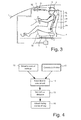
- FIG. 3 shows an alternative way of providing input data which relates to natural length changes of said driver 2.
- the embodiment shown in Fig. 3 comprises an image capturing device such as a camera 11 which is arranged close to the head of the driver 2.
- the camera 11 is configured for detecting the vertical position of the head of the driver 2, suitably by image analysis of captured images which gives information of the vertical position of the head.
- This input data can be provided at occasions corresponding to the morning and evening settings mentioned above, or can be provided at a number of times (or continuously) during the course of a day to provide input data corresponding to the length changes of the spine 8.
- This input data is then fed to the control unit 6 and used in order to set the relative vertical distance between the seat 3 and the rear view mirror 7 so that the driver 2 always has an optimal position as explained above.
- the embodiment as shown in Fig. 3 is particularly suitable to be used in vehicles which are already equipped with a camera which is used for safety reasons, for example for detecting if a driver is drowsy and may fall asleep. Such a camera may then additionally be used for detecting the position of, for example, the head or the eyes of the driver, in order to provide input data to be used for setting the relative vertical distanced between the seat 3 and the rear view mirror 7.
- Fig. 4 is a simplified flow chart describing the general principles of the invention. Initially, as mentioned above, it should be mentioned that input data related to the vertical position of the driver 2 is provided. This input data is provided either by manual settings of the driver 2, i.e. information as to the morning and evening settings as described above (step 12) or by information provided by a camera as described with reference to Fig. 3 (step 13).
- control unit 6 Said input data is then fed to the control unit 6 (step 14).
- the control unit 6 is configured for setting a vertical distance between the vehicle seat 3 and the rear view mirror 7 (step 15). This means that input data based on the natural length changes due to human spine decrease will be taken into account for the setting.
- the control unit 6 is suitably configured for adjusting (step 16) the setting of the vertical distance between the vehicle seat 3 and the rear view mirror 7 since the spine 8 will gradually be compressed during the day. The input data previously obtained will be used during such adjustments.
- control unit 6 can be used for storing settings for different persons, for example different members of a family using the same car, in order to provide optimal adjustments of the relative vertical distance between the seat and a further component based on each person's natural length changes due to spine compression.
- each person using the car would have to enter information regarding his or her identity before using the car, in order for the control unit to provide the correct settings for that particular person.
- identity information can be provided for example by means of a smart card, an NFC tag or other suitable technology.
- the relative vertical distance discussed above can relate to a distance between a vehicle seat and an additional vehicle component, wherein said additional vehicle component can be a mirror (i.e. both internal and external rear view mirror), an instrument panel, a steering wheel or another component.
- said additional vehicle component can be a mirror (i.e. both internal and external rear view mirror), an instrument panel, a steering wheel or another component.
Priority Applications (1)
| Application Number | Priority Date | Filing Date | Title |
|---|---|---|---|
| EP14173885.6A EP2960104B1 (de) | 2014-06-25 | 2014-06-25 | Verfahren und System zur Einstellung des relativen vertikalen Abstandes zwischen einem Fahrzeugsitz und mindestens einer weiteren Fahrzeugkomponente |
Applications Claiming Priority (1)
| Application Number | Priority Date | Filing Date | Title |
|---|---|---|---|
| EP14173885.6A EP2960104B1 (de) | 2014-06-25 | 2014-06-25 | Verfahren und System zur Einstellung des relativen vertikalen Abstandes zwischen einem Fahrzeugsitz und mindestens einer weiteren Fahrzeugkomponente |
Publications (2)
| Publication Number | Publication Date |
|---|---|
| EP2960104A1 true EP2960104A1 (de) | 2015-12-30 |
| EP2960104B1 EP2960104B1 (de) | 2017-04-19 |
Family
ID=50980977
Family Applications (1)
| Application Number | Title | Priority Date | Filing Date |
|---|---|---|---|
| EP14173885.6A Active EP2960104B1 (de) | 2014-06-25 | 2014-06-25 | Verfahren und System zur Einstellung des relativen vertikalen Abstandes zwischen einem Fahrzeugsitz und mindestens einer weiteren Fahrzeugkomponente |
Country Status (1)
| Country | Link |
|---|---|
| EP (1) | EP2960104B1 (de) |
Families Citing this family (1)
| Publication number | Priority date | Publication date | Assignee | Title |
|---|---|---|---|---|
| CN111196186B (zh) * | 2018-11-20 | 2021-07-20 | 宝沃汽车(中国)有限公司 | 车辆、车辆座椅及其控制系统、控制方法 |
Citations (3)
| Publication number | Priority date | Publication date | Assignee | Title |
|---|---|---|---|---|
| US4625329A (en) * | 1984-01-20 | 1986-11-25 | Nippondenso Co., Ltd. | Position analyzer for vehicle drivers |
| US4689537A (en) | 1985-03-23 | 1987-08-25 | Alps Electric Co., Ltd. | Driving position control system for automobiles |
| DE19519619A1 (de) | 1995-05-29 | 1996-12-05 | Henry Tunger | Statische sowie kontinuierliche Reflexionswinkel-Justierautomatik für Außen-/Innenspiegel mehrspuriger Kraftfahrzeuge |
-
2014
- 2014-06-25 EP EP14173885.6A patent/EP2960104B1/de active Active
Patent Citations (3)
| Publication number | Priority date | Publication date | Assignee | Title |
|---|---|---|---|---|
| US4625329A (en) * | 1984-01-20 | 1986-11-25 | Nippondenso Co., Ltd. | Position analyzer for vehicle drivers |
| US4689537A (en) | 1985-03-23 | 1987-08-25 | Alps Electric Co., Ltd. | Driving position control system for automobiles |
| DE19519619A1 (de) | 1995-05-29 | 1996-12-05 | Henry Tunger | Statische sowie kontinuierliche Reflexionswinkel-Justierautomatik für Außen-/Innenspiegel mehrspuriger Kraftfahrzeuge |
Also Published As
| Publication number | Publication date |
|---|---|
| EP2960104B1 (de) | 2017-04-19 |
Similar Documents
| Publication | Publication Date | Title |
|---|---|---|
| DE112014006621B4 (de) | Automatische Einstellvorrichtung, automatisches Einstellsystem und automatisches Einstellverfahren | |
| CN110588452B (zh) | 一种车辆座椅调节方法、系统及车载终端 | |
| US20180222414A1 (en) | Vehicle cabin monitoring system and temperature control | |
| US9942522B2 (en) | In-vehicle camera system | |
| EP1192061B1 (de) | Verfahren zur fahrdynamischen Adaption der Körperabstützung einer Sitzenden in einem Fahrzeugsitz und Fahrzeugsitz hierzu | |
| US20160236591A1 (en) | Method for presetting a vehicle seat | |
| DE102007023141B4 (de) | Verfahren zur Einstellung und/oder Nachstellung wenigstens eines Komfort-und/oder Sicherheitssystems in einem Kraftfahrzeug sowie Kraftfahrzeug | |
| US20130006478A1 (en) | Autonomous seat system of automotive vehicle and performing method thereof | |
| CN207523617U (zh) | 驾驶位置调节装置、服务器及系统 | |
| JP2014533633A (ja) | 座席位置を調整するための装置及び方法 | |
| US20180105071A1 (en) | Method for pre-adjusting vehicle seats | |
| DE102006032769A1 (de) | Einrichtung zur Optimierung von geometrischen Parametern von Fahrzeugeinbauten | |
| DE102016103017B4 (de) | Fahrzeugsitz | |
| EP2511149A3 (de) | Dynamisches Fahrzeugsteuerungssystem mit Schwerpunktausgleich basierend auf Frachtinformation | |
| US20160107574A1 (en) | Control unit for a motor vehicle having a camera for the driver's face, and method for imaging the face of a vehicle occupant | |
| US10882478B2 (en) | Movement-based comfort adjustment | |
| CN106080599A (zh) | 一种自动限速系统 | |
| EP2960104B1 (de) | Verfahren und System zur Einstellung des relativen vertikalen Abstandes zwischen einem Fahrzeugsitz und mindestens einer weiteren Fahrzeugkomponente | |
| DE102013221171A1 (de) | Anpassung von Fahrzeugfunktionen an Fahrfähigkeiten eines Fahrers | |
| CN110325384A (zh) | 车辆悬挂调节方法、系统及可调悬挂的车辆 | |
| CN107585063A (zh) | 一种基于云服务的汽车视角调整方法 | |
| CN105774707A (zh) | 一种汽车副驾驶位座椅智能调节系统 | |
| DE102017218444B4 (de) | Verfahren zum Betreiben eines Sicherheitssystems für eine Sitzanlage eines Kraftfahrzeugs und Sicherheitssystem für eine Sitzanlage eines Kraftfahrzeugs | |
| DE102021202295A1 (de) | Computerimplementiertes Verfahren, Vorrichtung und Computerprogramm zum Unterstützen einer Person bei einem Positionieren von Komponenten einer Innenausstattung eines automatisiert betreibbaren Fahrsystems | |
| CN212219997U (zh) | 一种汽车座椅头枕高度及温度自动调整装置 |
Legal Events
| Date | Code | Title | Description |
|---|---|---|---|
| PUAI | Public reference made under article 153(3) epc to a published international application that has entered the european phase |
Free format text: ORIGINAL CODE: 0009012 |
|
| AK | Designated contracting states |
Kind code of ref document: A1 Designated state(s): AL AT BE BG CH CY CZ DE DK EE ES FI FR GB GR HR HU IE IS IT LI LT LU LV MC MK MT NL NO PL PT RO RS SE SI SK SM TR |
|
| AX | Request for extension of the european patent |
Extension state: BA ME |
|
| 17P | Request for examination filed |
Effective date: 20160630 |
|
| RBV | Designated contracting states (corrected) |
Designated state(s): AL AT BE BG CH CY CZ DE DK EE ES FI FR GB GR HR HU IE IS IT LI LT LU LV MC MK MT NL NO PL PT RO RS SE SI SK SM TR |
|
| GRAP | Despatch of communication of intention to grant a patent |
Free format text: ORIGINAL CODE: EPIDOSNIGR1 |
|
| INTG | Intention to grant announced |
Effective date: 20161202 |
|
| GRAS | Grant fee paid |
Free format text: ORIGINAL CODE: EPIDOSNIGR3 |
|
| GRAA | (expected) grant |
Free format text: ORIGINAL CODE: 0009210 |
|
| AK | Designated contracting states |
Kind code of ref document: B1 Designated state(s): AL AT BE BG CH CY CZ DE DK EE ES FI FR GB GR HR HU IE IS IT LI LT LU LV MC MK MT NL NO PL PT RO RS SE SI SK SM TR |
|
| REG | Reference to a national code |
Ref country code: GB Ref legal event code: FG4D |
|
| REG | Reference to a national code |
Ref country code: CH Ref legal event code: EP |
|
| REG | Reference to a national code |
Ref country code: AT Ref legal event code: REF Ref document number: 885605 Country of ref document: AT Kind code of ref document: T Effective date: 20170515 |
|
| REG | Reference to a national code |
Ref country code: IE Ref legal event code: FG4D |
|
| REG | Reference to a national code |
Ref country code: DE Ref legal event code: R096 Ref document number: 602014008684 Country of ref document: DE |
|
| REG | Reference to a national code |
Ref country code: SE Ref legal event code: TRGR |
|
| REG | Reference to a national code |
Ref country code: NL Ref legal event code: MP Effective date: 20170419 |
|
| REG | Reference to a national code |
Ref country code: LT Ref legal event code: MG4D |
|
| REG | Reference to a national code |
Ref country code: AT Ref legal event code: MK05 Ref document number: 885605 Country of ref document: AT Kind code of ref document: T Effective date: 20170419 |
|
| PG25 | Lapsed in a contracting state [announced via postgrant information from national office to epo] |
Ref country code: NL Free format text: LAPSE BECAUSE OF FAILURE TO SUBMIT A TRANSLATION OF THE DESCRIPTION OR TO PAY THE FEE WITHIN THE PRESCRIBED TIME-LIMIT Effective date: 20170419 |
|
| PG25 | Lapsed in a contracting state [announced via postgrant information from national office to epo] |
Ref country code: ES Free format text: LAPSE BECAUSE OF FAILURE TO SUBMIT A TRANSLATION OF THE DESCRIPTION OR TO PAY THE FEE WITHIN THE PRESCRIBED TIME-LIMIT Effective date: 20170419 Ref country code: FI Free format text: LAPSE BECAUSE OF FAILURE TO SUBMIT A TRANSLATION OF THE DESCRIPTION OR TO PAY THE FEE WITHIN THE PRESCRIBED TIME-LIMIT Effective date: 20170419 Ref country code: NO Free format text: LAPSE BECAUSE OF FAILURE TO SUBMIT A TRANSLATION OF THE DESCRIPTION OR TO PAY THE FEE WITHIN THE PRESCRIBED TIME-LIMIT Effective date: 20170719 Ref country code: HR Free format text: LAPSE BECAUSE OF FAILURE TO SUBMIT A TRANSLATION OF THE DESCRIPTION OR TO PAY THE FEE WITHIN THE PRESCRIBED TIME-LIMIT Effective date: 20170419 Ref country code: LT Free format text: LAPSE BECAUSE OF FAILURE TO SUBMIT A TRANSLATION OF THE DESCRIPTION OR TO PAY THE FEE WITHIN THE PRESCRIBED TIME-LIMIT Effective date: 20170419 Ref country code: GR Free format text: LAPSE BECAUSE OF FAILURE TO SUBMIT A TRANSLATION OF THE DESCRIPTION OR TO PAY THE FEE WITHIN THE PRESCRIBED TIME-LIMIT Effective date: 20170720 Ref country code: AT Free format text: LAPSE BECAUSE OF FAILURE TO SUBMIT A TRANSLATION OF THE DESCRIPTION OR TO PAY THE FEE WITHIN THE PRESCRIBED TIME-LIMIT Effective date: 20170419 |
|
| PG25 | Lapsed in a contracting state [announced via postgrant information from national office to epo] |
Ref country code: IS Free format text: LAPSE BECAUSE OF FAILURE TO SUBMIT A TRANSLATION OF THE DESCRIPTION OR TO PAY THE FEE WITHIN THE PRESCRIBED TIME-LIMIT Effective date: 20170819 Ref country code: BG Free format text: LAPSE BECAUSE OF FAILURE TO SUBMIT A TRANSLATION OF THE DESCRIPTION OR TO PAY THE FEE WITHIN THE PRESCRIBED TIME-LIMIT Effective date: 20170719 Ref country code: RS Free format text: LAPSE BECAUSE OF FAILURE TO SUBMIT A TRANSLATION OF THE DESCRIPTION OR TO PAY THE FEE WITHIN THE PRESCRIBED TIME-LIMIT Effective date: 20170419 Ref country code: PL Free format text: LAPSE BECAUSE OF FAILURE TO SUBMIT A TRANSLATION OF THE DESCRIPTION OR TO PAY THE FEE WITHIN THE PRESCRIBED TIME-LIMIT Effective date: 20170419 Ref country code: LV Free format text: LAPSE BECAUSE OF FAILURE TO SUBMIT A TRANSLATION OF THE DESCRIPTION OR TO PAY THE FEE WITHIN THE PRESCRIBED TIME-LIMIT Effective date: 20170419 |
|
| REG | Reference to a national code |
Ref country code: DE Ref legal event code: R097 Ref document number: 602014008684 Country of ref document: DE |
|
| PG25 | Lapsed in a contracting state [announced via postgrant information from national office to epo] |
Ref country code: EE Free format text: LAPSE BECAUSE OF FAILURE TO SUBMIT A TRANSLATION OF THE DESCRIPTION OR TO PAY THE FEE WITHIN THE PRESCRIBED TIME-LIMIT Effective date: 20170419 Ref country code: RO Free format text: LAPSE BECAUSE OF FAILURE TO SUBMIT A TRANSLATION OF THE DESCRIPTION OR TO PAY THE FEE WITHIN THE PRESCRIBED TIME-LIMIT Effective date: 20170419 Ref country code: SK Free format text: LAPSE BECAUSE OF FAILURE TO SUBMIT A TRANSLATION OF THE DESCRIPTION OR TO PAY THE FEE WITHIN THE PRESCRIBED TIME-LIMIT Effective date: 20170419 Ref country code: CZ Free format text: LAPSE BECAUSE OF FAILURE TO SUBMIT A TRANSLATION OF THE DESCRIPTION OR TO PAY THE FEE WITHIN THE PRESCRIBED TIME-LIMIT Effective date: 20170419 Ref country code: MC Free format text: LAPSE BECAUSE OF FAILURE TO SUBMIT A TRANSLATION OF THE DESCRIPTION OR TO PAY THE FEE WITHIN THE PRESCRIBED TIME-LIMIT Effective date: 20170419 Ref country code: DK Free format text: LAPSE BECAUSE OF FAILURE TO SUBMIT A TRANSLATION OF THE DESCRIPTION OR TO PAY THE FEE WITHIN THE PRESCRIBED TIME-LIMIT Effective date: 20170419 |
|
| REG | Reference to a national code |
Ref country code: CH Ref legal event code: PL |
|
| PLBE | No opposition filed within time limit |
Free format text: ORIGINAL CODE: 0009261 |
|
| STAA | Information on the status of an ep patent application or granted ep patent |
Free format text: STATUS: NO OPPOSITION FILED WITHIN TIME LIMIT |
|
| PG25 | Lapsed in a contracting state [announced via postgrant information from national office to epo] |
Ref country code: SM Free format text: LAPSE BECAUSE OF FAILURE TO SUBMIT A TRANSLATION OF THE DESCRIPTION OR TO PAY THE FEE WITHIN THE PRESCRIBED TIME-LIMIT Effective date: 20170419 Ref country code: IT Free format text: LAPSE BECAUSE OF FAILURE TO SUBMIT A TRANSLATION OF THE DESCRIPTION OR TO PAY THE FEE WITHIN THE PRESCRIBED TIME-LIMIT Effective date: 20170419 |
|
| REG | Reference to a national code |
Ref country code: IE Ref legal event code: MM4A |
|
| 26N | No opposition filed |
Effective date: 20180122 |
|
| REG | Reference to a national code |
Ref country code: FR Ref legal event code: ST Effective date: 20180228 |
|
| PG25 | Lapsed in a contracting state [announced via postgrant information from national office to epo] |
Ref country code: LU Free format text: LAPSE BECAUSE OF NON-PAYMENT OF DUE FEES Effective date: 20170625 Ref country code: IE Free format text: LAPSE BECAUSE OF NON-PAYMENT OF DUE FEES Effective date: 20170625 Ref country code: LI Free format text: LAPSE BECAUSE OF NON-PAYMENT OF DUE FEES Effective date: 20170630 Ref country code: CH Free format text: LAPSE BECAUSE OF NON-PAYMENT OF DUE FEES Effective date: 20170630 |
|
| PG25 | Lapsed in a contracting state [announced via postgrant information from national office to epo] |
Ref country code: SI Free format text: LAPSE BECAUSE OF FAILURE TO SUBMIT A TRANSLATION OF THE DESCRIPTION OR TO PAY THE FEE WITHIN THE PRESCRIBED TIME-LIMIT Effective date: 20170419 Ref country code: FR Free format text: LAPSE BECAUSE OF NON-PAYMENT OF DUE FEES Effective date: 20170630 |
|
| REG | Reference to a national code |
Ref country code: BE Ref legal event code: MM Effective date: 20170630 |
|
| PG25 | Lapsed in a contracting state [announced via postgrant information from national office to epo] |
Ref country code: BE Free format text: LAPSE BECAUSE OF NON-PAYMENT OF DUE FEES Effective date: 20170630 |
|
| PG25 | Lapsed in a contracting state [announced via postgrant information from national office to epo] |
Ref country code: MT Free format text: LAPSE BECAUSE OF NON-PAYMENT OF DUE FEES Effective date: 20170625 |
|
| PG25 | Lapsed in a contracting state [announced via postgrant information from national office to epo] |
Ref country code: HU Free format text: LAPSE BECAUSE OF FAILURE TO SUBMIT A TRANSLATION OF THE DESCRIPTION OR TO PAY THE FEE WITHIN THE PRESCRIBED TIME-LIMIT; INVALID AB INITIO Effective date: 20140625 |
|
| PGFP | Annual fee paid to national office [announced via postgrant information from national office to epo] |
Ref country code: SE Payment date: 20190620 Year of fee payment: 6 |
|
| PG25 | Lapsed in a contracting state [announced via postgrant information from national office to epo] |
Ref country code: CY Free format text: LAPSE BECAUSE OF FAILURE TO SUBMIT A TRANSLATION OF THE DESCRIPTION OR TO PAY THE FEE WITHIN THE PRESCRIBED TIME-LIMIT Effective date: 20170419 |
|
| PGFP | Annual fee paid to national office [announced via postgrant information from national office to epo] |
Ref country code: GB Payment date: 20190613 Year of fee payment: 6 |
|
| PG25 | Lapsed in a contracting state [announced via postgrant information from national office to epo] |
Ref country code: MK Free format text: LAPSE BECAUSE OF FAILURE TO SUBMIT A TRANSLATION OF THE DESCRIPTION OR TO PAY THE FEE WITHIN THE PRESCRIBED TIME-LIMIT Effective date: 20170419 |
|
| PG25 | Lapsed in a contracting state [announced via postgrant information from national office to epo] |
Ref country code: TR Free format text: LAPSE BECAUSE OF FAILURE TO SUBMIT A TRANSLATION OF THE DESCRIPTION OR TO PAY THE FEE WITHIN THE PRESCRIBED TIME-LIMIT Effective date: 20170419 |
|
| PG25 | Lapsed in a contracting state [announced via postgrant information from national office to epo] |
Ref country code: PT Free format text: LAPSE BECAUSE OF FAILURE TO SUBMIT A TRANSLATION OF THE DESCRIPTION OR TO PAY THE FEE WITHIN THE PRESCRIBED TIME-LIMIT Effective date: 20170419 |
|
| PG25 | Lapsed in a contracting state [announced via postgrant information from national office to epo] |
Ref country code: AL Free format text: LAPSE BECAUSE OF FAILURE TO SUBMIT A TRANSLATION OF THE DESCRIPTION OR TO PAY THE FEE WITHIN THE PRESCRIBED TIME-LIMIT Effective date: 20170419 |
|
| GBPC | Gb: european patent ceased through non-payment of renewal fee |
Effective date: 20200625 |
|
| PG25 | Lapsed in a contracting state [announced via postgrant information from national office to epo] |
Ref country code: GB Free format text: LAPSE BECAUSE OF NON-PAYMENT OF DUE FEES Effective date: 20200625 |
|
| PG25 | Lapsed in a contracting state [announced via postgrant information from national office to epo] |
Ref country code: SE Free format text: LAPSE BECAUSE OF NON-PAYMENT OF DUE FEES Effective date: 20200626 |
|
| REG | Reference to a national code |
Ref country code: SE Ref legal event code: EUG |
|
| PGFP | Annual fee paid to national office [announced via postgrant information from national office to epo] |
Ref country code: DE Payment date: 20230523 Year of fee payment: 10 |
|
| P01 | Opt-out of the competence of the unified patent court (upc) registered |
Effective date: 20231212 |