EP2960100B1 - Système de robot de service - Google Patents
Système de robot de service Download PDFInfo
- Publication number
- EP2960100B1 EP2960100B1 EP15170834.4A EP15170834A EP2960100B1 EP 2960100 B1 EP2960100 B1 EP 2960100B1 EP 15170834 A EP15170834 A EP 15170834A EP 2960100 B1 EP2960100 B1 EP 2960100B1
- Authority
- EP
- European Patent Office
- Prior art keywords
- base station
- service robot
- unit
- contact charging
- flat contact
- Prior art date
- Legal status (The legal status is an assumption and is not a legal conclusion. Google has not performed a legal analysis and makes no representation as to the accuracy of the status listed.)
- Active
Links
Images


Classifications
-
- G—PHYSICS
- G05—CONTROLLING; REGULATING
- G05D—SYSTEMS FOR CONTROLLING OR REGULATING NON-ELECTRIC VARIABLES
- G05D1/00—Control of position, course, altitude or attitude of land, water, air or space vehicles, e.g. using automatic pilots
- G05D1/02—Control of position or course in two dimensions
- G05D1/021—Control of position or course in two dimensions specially adapted to land vehicles
- G05D1/0212—Control of position or course in two dimensions specially adapted to land vehicles with means for defining a desired trajectory
- G05D1/0225—Control of position or course in two dimensions specially adapted to land vehicles with means for defining a desired trajectory involving docking at a fixed facility, e.g. base station or loading bay
-
- B—PERFORMING OPERATIONS; TRANSPORTING
- B60—VEHICLES IN GENERAL
- B60L—PROPULSION OF ELECTRICALLY-PROPELLED VEHICLES; SUPPLYING ELECTRIC POWER FOR AUXILIARY EQUIPMENT OF ELECTRICALLY-PROPELLED VEHICLES; ELECTRODYNAMIC BRAKE SYSTEMS FOR VEHICLES IN GENERAL; MAGNETIC SUSPENSION OR LEVITATION FOR VEHICLES; MONITORING OPERATING VARIABLES OF ELECTRICALLY-PROPELLED VEHICLES; ELECTRIC SAFETY DEVICES FOR ELECTRICALLY-PROPELLED VEHICLES
- B60L53/00—Methods of charging batteries, specially adapted for electric vehicles; Charging stations or on-board charging equipment therefor; Exchange of energy storage elements in electric vehicles
- B60L53/10—Methods of charging batteries, specially adapted for electric vehicles; Charging stations or on-board charging equipment therefor; Exchange of energy storage elements in electric vehicles characterised by the energy transfer between the charging station and the vehicle
- B60L53/14—Conductive energy transfer
- B60L53/16—Connectors, e.g. plugs or sockets, specially adapted for charging electric vehicles
-
- B—PERFORMING OPERATIONS; TRANSPORTING
- B60—VEHICLES IN GENERAL
- B60L—PROPULSION OF ELECTRICALLY-PROPELLED VEHICLES; SUPPLYING ELECTRIC POWER FOR AUXILIARY EQUIPMENT OF ELECTRICALLY-PROPELLED VEHICLES; ELECTRODYNAMIC BRAKE SYSTEMS FOR VEHICLES IN GENERAL; MAGNETIC SUSPENSION OR LEVITATION FOR VEHICLES; MONITORING OPERATING VARIABLES OF ELECTRICALLY-PROPELLED VEHICLES; ELECTRIC SAFETY DEVICES FOR ELECTRICALLY-PROPELLED VEHICLES
- B60L53/00—Methods of charging batteries, specially adapted for electric vehicles; Charging stations or on-board charging equipment therefor; Exchange of energy storage elements in electric vehicles
- B60L53/30—Constructional details of charging stations
- B60L53/35—Means for automatic or assisted adjustment of the relative position of charging devices and vehicles
- B60L53/36—Means for automatic or assisted adjustment of the relative position of charging devices and vehicles by positioning the vehicle
-
- H—ELECTRICITY
- H01—ELECTRIC ELEMENTS
- H01R—ELECTRICALLY-CONDUCTIVE CONNECTIONS; STRUCTURAL ASSOCIATIONS OF A PLURALITY OF MUTUALLY-INSULATED ELECTRICAL CONNECTING ELEMENTS; COUPLING DEVICES; CURRENT COLLECTORS
- H01R13/00—Details of coupling devices of the kinds covered by groups H01R12/70 or H01R24/00 - H01R33/00
- H01R13/62—Means for facilitating engagement or disengagement of coupling parts or for holding them in engagement
- H01R13/629—Additional means for facilitating engagement or disengagement of coupling parts, e.g. aligning or guiding means, levers, gas pressure electrical locking indicators, manufacturing tolerances
- H01R13/631—Additional means for facilitating engagement or disengagement of coupling parts, e.g. aligning or guiding means, levers, gas pressure electrical locking indicators, manufacturing tolerances for engagement only
- H01R13/6315—Additional means for facilitating engagement or disengagement of coupling parts, e.g. aligning or guiding means, levers, gas pressure electrical locking indicators, manufacturing tolerances for engagement only allowing relative movement between coupling parts, e.g. floating connection
-
- H—ELECTRICITY
- H01—ELECTRIC ELEMENTS
- H01R—ELECTRICALLY-CONDUCTIVE CONNECTIONS; STRUCTURAL ASSOCIATIONS OF A PLURALITY OF MUTUALLY-INSULATED ELECTRICAL CONNECTING ELEMENTS; COUPLING DEVICES; CURRENT COLLECTORS
- H01R2201/00—Connectors or connections adapted for particular applications
- H01R2201/26—Connectors or connections adapted for particular applications for vehicles
-
- Y—GENERAL TAGGING OF NEW TECHNOLOGICAL DEVELOPMENTS; GENERAL TAGGING OF CROSS-SECTIONAL TECHNOLOGIES SPANNING OVER SEVERAL SECTIONS OF THE IPC; TECHNICAL SUBJECTS COVERED BY FORMER USPC CROSS-REFERENCE ART COLLECTIONS [XRACs] AND DIGESTS
- Y02—TECHNOLOGIES OR APPLICATIONS FOR MITIGATION OR ADAPTATION AGAINST CLIMATE CHANGE
- Y02T—CLIMATE CHANGE MITIGATION TECHNOLOGIES RELATED TO TRANSPORTATION
- Y02T10/00—Road transport of goods or passengers
- Y02T10/60—Other road transportation technologies with climate change mitigation effect
- Y02T10/70—Energy storage systems for electromobility, e.g. batteries
-
- Y—GENERAL TAGGING OF NEW TECHNOLOGICAL DEVELOPMENTS; GENERAL TAGGING OF CROSS-SECTIONAL TECHNOLOGIES SPANNING OVER SEVERAL SECTIONS OF THE IPC; TECHNICAL SUBJECTS COVERED BY FORMER USPC CROSS-REFERENCE ART COLLECTIONS [XRACs] AND DIGESTS
- Y02—TECHNOLOGIES OR APPLICATIONS FOR MITIGATION OR ADAPTATION AGAINST CLIMATE CHANGE
- Y02T—CLIMATE CHANGE MITIGATION TECHNOLOGIES RELATED TO TRANSPORTATION
- Y02T10/00—Road transport of goods or passengers
- Y02T10/60—Other road transportation technologies with climate change mitigation effect
- Y02T10/7072—Electromobility specific charging systems or methods for batteries, ultracapacitors, supercapacitors or double-layer capacitors
-
- Y—GENERAL TAGGING OF NEW TECHNOLOGICAL DEVELOPMENTS; GENERAL TAGGING OF CROSS-SECTIONAL TECHNOLOGIES SPANNING OVER SEVERAL SECTIONS OF THE IPC; TECHNICAL SUBJECTS COVERED BY FORMER USPC CROSS-REFERENCE ART COLLECTIONS [XRACs] AND DIGESTS
- Y02—TECHNOLOGIES OR APPLICATIONS FOR MITIGATION OR ADAPTATION AGAINST CLIMATE CHANGE
- Y02T—CLIMATE CHANGE MITIGATION TECHNOLOGIES RELATED TO TRANSPORTATION
- Y02T90/00—Enabling technologies or technologies with a potential or indirect contribution to GHG emissions mitigation
- Y02T90/10—Technologies relating to charging of electric vehicles
- Y02T90/12—Electric charging stations
-
- Y—GENERAL TAGGING OF NEW TECHNOLOGICAL DEVELOPMENTS; GENERAL TAGGING OF CROSS-SECTIONAL TECHNOLOGIES SPANNING OVER SEVERAL SECTIONS OF THE IPC; TECHNICAL SUBJECTS COVERED BY FORMER USPC CROSS-REFERENCE ART COLLECTIONS [XRACs] AND DIGESTS
- Y02—TECHNOLOGIES OR APPLICATIONS FOR MITIGATION OR ADAPTATION AGAINST CLIMATE CHANGE
- Y02T—CLIMATE CHANGE MITIGATION TECHNOLOGIES RELATED TO TRANSPORTATION
- Y02T90/00—Enabling technologies or technologies with a potential or indirect contribution to GHG emissions mitigation
- Y02T90/10—Technologies relating to charging of electric vehicles
- Y02T90/14—Plug-in electric vehicles
Definitions
- Service robot systems in particular lawn mower systems, are already known, which have a service robot having an energy storage unit, in particular an autonomous lawnmower, and a base station which is provided in at least one state for energy supply of the energy storage unit of the service robot.
- the service robot or the base station has at least two flat contact charging elements.
- the invention relates to a service robot system, in particular of a lawn mower system, with at least one service robot, in particular an autonomous lawn mower comprising at least one energy storage unit, and with at least one base station at least to a power supply of the energy storage unit in at least one state, wherein the service robot or the Base station has at least two flat contact charging elements.
- the at least two flat contact charging elements are provided for enabling a charge docking process of the service robot at the base station at least in an angular range of at least more than 15 °.
- the angle range extends in particular, starting from a longitudinal axis, in particular a symmetry longitudinal axis, at least one of the at least two flat contact charging elements, wherein in particular in each case 50% of the angular range extending from the longitudinal axis in two opposite directions.
- the at least two flat contact charging elements are preferably provided to allow a charge docking process of the service robot at the base station at least in an angular range of at least more than 30 ° and particularly preferably at least more than 40 °.
- the at least two flat contact charging elements are particularly preferably provided to allow a Ladeandock polish the service robot at the base station from different directions.
- the at least two flat contact charging elements are preferably provided to compensate for at least one offset, in particular an angular offset or a parallel offset, between the longitudinal axis of at least one of the at least two flat contact charging elements relative to at least one longitudinal axis of a mating contact unit or the base station during a charge docking process.
- offset in particular an angular offset or a parallel offset
- By “intended” is intended to be understood in particular specifically designed and / or specially equipped.
- the element and / or the unit fulfill / fulfill and / or execute this specific function in at least one application and / or operating state.
- a “dock docking process” is to be understood here in particular as meaning a process in which the service robot approaches the base station and the at least two flat contact charging elements supply energy to the energy storage unit with the mating contact unit, in particular with at least two mating contact elements of the mating contact unit, to transfer energy, in particular electrical energy transfer , are in contact.
- the service robot initiates the charge docking process automatically in a manner already known to a person skilled in the art, in particular as a result of a detection of a falling below of an energy storage limit value of the energy storage unit.
- a “flat contact charging element” is to be understood here in particular as a contact charging element which has a component thickness which is many times, in particular at least twice, preferably at least three times and more preferably at least four times smaller than an extension running transversely thereto , in particular a main extension, of the contact charging element. Particularly preferred is the component thickness along measured at least substantially parallel to a vertical axis of the base station or the service robot direction.
- “Substantially parallel” is to be understood here as meaning, in particular, an alignment of a direction relative to a reference direction, in particular in a plane, wherein the direction relative to the reference direction is a deviation, in particular less than 8 °, advantageously less than 5 ° and particularly advantageously less than 2 °.
- a main extension, in particular a largest surface extension, of the respective flat contact charging element particularly preferably extends in a plane which extends at least substantially perpendicular to the vertical axis of the base station or the service robot.
- the flat contact charging element (s) may have any cross-sectional shape that appears expedient to a person skilled in the art, such as, for example, a polygonal cross-sectional shape or a non-polygonal cross-sectional shape.
- the flat contact charging member (s) may have a round cross-sectional shape, a square cross-sectional shape, a triangular cross-sectional shape, a rectangular cross-sectional shape, an elliptical cross-sectional shape, an oval cross-sectional shape, or the like.
- the vertical axis of the service robot preferably runs at least substantially perpendicular to a base contact surface of the service robot, in particular a ground contact surface of a chassis unit of the service robot.
- the vertical axis of the base station preferably runs at least substantially perpendicular to a base support surface of the base station, in particular a base support surface of a base plate of the base station.
- substantially perpendicular is intended here to define, in particular, an orientation of a direction relative to a reference direction, the direction and the reference direction, in particular in one plane, including an angle of 90 ° and the angle a maximum deviation of, in particular, less than 8 °, advantageously less than 5 ° and particularly advantageously less than 2 °.
- the service robot is particularly preferably designed as an autonomous locomotion device.
- An "autonomous locomotion device” is to be understood here in particular as a device that automatically operates in an area and / or in an area an environment moves, oriented or automatically navigated, in particular moves itself automatically after a learning process in an area and / or in an environment and / or oriented.
- the term "autonomously move and / or orient” should here in particular define a locomotion, an orientation and / or a navigation of the autonomous locomotion device, in particular after a learning process, without human intervention.
- the service robot automatically moves in an area and / or in an environment after a learning process performed by an operator with the service robot, or orients itself automatically in an area and / or in an environment.
- the service robot can have any devices that appear meaningful to a person skilled in the art and already known to him, such as a GPS device, a compass device, a surround wire device, an optical device or the like.
- the service robot can do this be designed as an autonomous lawnmower, as an autonomous vacuum cleaner, as an autonomous sweeper, as an autonomous transport vehicle, as an autonomous aircraft, as an autonomous agricultural device o.
- the service robot is preferably in the form of an autonomous lawnmower, which is intended to remove and / or work on a working surface designed as a turf surface and / or a working environment designed as a garden environment.
- the service robot particularly preferably has a work surface processing unit designed as a mowing unit.
- the work surface processing unit can in this case by means of a drive unit of the service robot, which is provided at least for driving the chassis unit of the service robot, or by means of a separate mower drive unit, which is formed separately from the drive unit for driving the chassis unit driven.
- a load docking process of the service robot at the base station from different directions can be made possible.
- a high flexibility with regard to a charge docking process can advantageously be achieved.
- the active use of alternative access routes to protect the lawn or to achieve a short approach path when different sectors of the work area are processed in different time windows can be advantageously achieved by means of the inventive design.
- the load docking process of the service robot relative to a center axis of the base station relative to a central axis of the service robot in an angular range of at least ⁇ 7.5 ° is possible.
- the load docking process of the service robot relative to a center axis of the base station relative to a center axis of the service robot is made possible in an angle range of more than ⁇ 10 ° and particularly preferably more than ⁇ 15 °.
- the center axis of the base station particularly preferably extends at least substantially perpendicular to the vertical axis of the base station.
- the center axis of the service robot preferably runs at least substantially perpendicular to the vertical axis of the service robot.
- a loading docking process of the service robot at the base station in different angular sectors can be made possible.
- the at least two flat contact charging elements are arranged vertically offset from one another.
- the at least two flat contact charging elements viewed along a direction extending at least substantially parallel to the vertical axis of the service robot or the base station, are arranged vertically offset from one another.
- the at least two flat contact charging elements are arranged in two horizontal planes extending at least substantially parallel to one another. The horizontal planes in this case run at least substantially perpendicular to the vertical axis of the service robot or the base station.
- the at least two flat contact charging elements viewed along a direction extending at least substantially perpendicular to the vertical axis of the service robot or the base station, project at least over a partial area of the service robot or the base station.
- the at least two flat contact charging elements viewed in the respective horizontal plane, have a maximum transverse extent, which is smaller by a multiple than a maximum longitudinal extent.
- the at least two flat contact charging elements, viewed in the respective horizontal plane to have a polygonal configuration, a circular sector-like configuration, an elliptical-sector-like configuration or the like.
- the at least two flat contact charging elements viewed in the respective horizontal plane, have a circular configuration in which, in particular, a maximum transverse extension corresponds to a maximum longitudinal extension.
- the at least two flat contact charging elements viewed in a horizontal plane, are arranged one behind the other and are intended to receive a contact charging element with a circular cross section, such as a jack-type contact charging element.
- the at least two flat contact charging elements are at least substantially aligned with each other.
- the term "at least substantially aligned” is to be understood here to mean in particular an orientation of the at least two flat contact charging elements relative to one another, wherein at least two outer edges of the at least two flat contact charging elements, viewed along a direction extending at least substantially parallel to the vertical axis of the service robot or the base station, are arranged overlapping or, viewed along a direction extending at least substantially perpendicular to the vertical axis of the service robot or the base station, have a maximum offset of in particular less than 20 mm, preferably less than 15 mm and particularly preferably less than 10 mm.
- the at least two flat contact charging elements are plate-like, disk-like or tongue-like.
- the at least two flat contact charging elements are preferably formed as flat components, which are at least substantially flat, at least in an unloaded state.
- the at least two flat contact charging elements may have another configuration that appears appropriate to a person skilled in the art.
- the at least two flat contact charging elements viewed in a plane extending at least substantially perpendicular to the vertical axis of the service robot or the base station, may have a polygonal configuration, a circular sector-like configuration, an elliptical sector-like configuration or the like.
- the service robot system comprises at least one mating contact unit, which is provided for receiving at least one of the at least two flat contact charging elements and which is configured such that the load docking process of the service robot relative to the center axis of the base station to the central axis of the service robot in an angular range of at least ⁇ 7.5 ° is possible.
- the mating contact unit is designed such that the load docking process of the service robot relative to a center axis of the base station relative to a center axis of the service robot in an angular range of more than ⁇ 10 ° and more preferably greater than ⁇ 15 ° is possible.
- the service robot system comprises at least one mating contact unit which is provided for receiving at least one of the at least two flat contact charging elements and which has an insertion opening which has a minimum width extension which corresponds to at least three times a maximum width extension of one of the at least two flat contact charging elements ,
- the minimum width of the insertion opening preferably runs in a plane which extends at least substantially perpendicular to the vertical axis of the service robot or the base station.
- the base station preferably has the mating contact unit.
- the service robot preferably has the mating contact unit.
- the service robot system comprises at least one mating contact unit which has at least one mating contact element, which, viewed in a plane extending at least substantially perpendicular to the vertical axis of the service robot or the base station horizontal plane.
- the service robot system comprises at least one mating contact unit, which is provided for receiving at least one of the at least two flat contact charging elements, and which extends at least over an angular range of more than 30 °.
- an insertion opening of the mating contact unit extends over an angular range of more than 30 °, preferably over an angular range of more than 60 ° and particularly preferably over an angular range of more than 90 °.
- the service robot preferably has the mating contact unit, which extends over an angular range of more than 60 °, in particular on a front side of the service robot.
- the service robot viewed in a plane extending at least substantially perpendicular to the vertical axis of the service robot, preferably has a rounded front side, in particular a circular segment-like front side.
- the service robot system comprises at least one insulator element which is arranged between the at least two flat contact charging elements and at least partially bears against the at least two flat contact charging elements.
- the isolator element is preferably arranged, viewed along a direction extending at least substantially parallel to the vertical axis of the service robot or the base station, between the at least two flat contact charging elements.
- the at least two flat contact charging elements lie flat against the insulator element.
- the at least two flat contact charging elements rest only partially on the insulator element.
- advantageously a risk of short circuit due to contact of the at least two flat contact charging elements can be advantageously kept low.
- advantageously a high operator safety and a high product safety can be achieved.
- the insulator element extend beyond at least one of the at least two flat contact charging elements, at least along one direction.
- the insulator element preferably extends along at least one of the at least two flat contact charging elements along an at least substantially transversely, in particular perpendicular, direction to the vertical axis of the service robot or the base station.
- the insulator element preferably extends beyond both of the at least two flat contact charging elements at least along one direction.
- the at least two flat contact charging elements are mounted so as to be movable relative to one another.
- at least one of the at least two flat contact charging elements is movably mounted on the service robot or on the base station.
- the term "movably mounted” is intended here to define in particular a mounting of a unit and / or an element, wherein the unit and / or the element, in particular decoupled from an elastic deformation of the unit and / or the element, a movement possibility along at least a distance greater than 5 mm, preferably greater than 10 mm and particularly preferably greater than 20 mm and / or a possibility of movement about at least one axis by an angle greater than 15 °, preferably greater than 30 ° and more preferably greater than 45 °.
- At least one of the at least two flat contact charging elements is movably mounted relative to a housing of the service robot in an embodiment of the service robot with the at least two flat contact charging elements.
- at least one of the at least two flat contact charging elements is preferably mounted movably relative to a housing of the base station.
- at least one of the at least two flat contact charging elements is mounted in a translationally movable manner, for example along a direction extending at least substantially parallel to the vertical axis, or at least one of the at least two flat contact charging elements is pivotably mounted.
- a centering of the at least one of the at least two flat contact charging element can advantageously be achieved via at least one solid-state articulation, at least one spring tongue, by means of a guide unit and a tension or compression spring interacting therewith, or via another element which appears expedient to a person skilled in the art.
- an additional security function of the service robot can advantageously be made possible in a state of the service robot docked to the base station.
- an anti-theft function can be realized.
- the service robot system has at least one position holding unit which is provided to hold the service robot at least in a loading position relative to the base station.
- the position-holding unit can in this case be formed, for example, by at least one of the movably mounted flat contact charging elements or by both flat contact charging elements.
- the position holding unit is formed separately from the at least two flat contact charging elements, such as in an embodiment of the position holding unit as a magnetic holding unit, as a recess into which the service robot when starting the base station moves o. The like.
- the service robot system comprises at least one contact contact protection unit which has at least one movably mounted contact contact protection element which is provided to cover at least one of the at least two flat contact charging elements or at least one counter contact charging element of a counter contact charging unit in at least one state.
- the movably mounted contact-contact protection element it is conceivable for the movably mounted contact-contact protection element to be arranged directly on at least one of the at least two flat contact charging elements or for the contact-contact protection element to cover both flat contact charging elements in at least one state.
- the service robot system preferably additionally comprises at least one release unit, which is provided to release at least one maximum charging voltage in at least one charging position of the autonomous service robot relative to the base station as a function of at least one characteristic.
- the service robot and the base station may each comprise at least one communication unit which is provided for transmitting data, in particular electronic data or digital signals.
- the communication unit is preferably designed as a wireless communication unit.
- the communication unit may be configured as a WLAN communication unit, a Bluetooth communication unit, a radio communication unit, an RFID communication unit, an NFC unit, an infrared communication unit, a mobile radio network communication unit or the like.
- the communication unit is provided for bidirectional data transmission.
- a secure contact When contacting the at least two flat contact charging elements and the mating contact unit, a secure contact can be verified as a result of communication between the service robot and the base station. Thus, after a verification of a secure contact, a high charging voltage can be switched to the at least two flat contact charging elements and the mating contact unit.
- the communication between the service robot and the base station can here by means of a special additional electrical contacting, by means of the communication unit, by means of a magnetic coding, by means of a mechanical coding o.
- the service robot system comprises at least one data logger unit which is provided to log and evaluate at least one load parameter of at least two different service robots.
- a "data logger unit” is to be understood here in particular as a unit which at least receives data, in particular digital data, via an interface and stores it on a storage medium.
- the data logger unit may comprise a sensor unit.
- the data logger unit comprises, as an alternative or in addition to the sensor unit, at least one operating program which processes data and stores it in the storage medium.
- a service robot in particular an autonomous lawnmower, a service robot system according to the invention is proposed. It can be advantageously realized a service robot, by means of which advantageously a Ladeandockfrac from different directions is possible.
- the base station may in this case comprise a garden lamp unit, a motion detector unit and / or a weather station unit.
- a base station By means of the embodiment according to the invention can advantageously be realized a base station, by means of which advantageously a Ladeandockfrac from different directions is possible.
- the base station comprises at least one auxiliary fuel refueling unit which is provided to refuel at least one service robot in at least one state with at least one auxiliary substance.
- auxiliary fuel refueling unit is to be understood here as meaning, in particular, a unit which is provided to refuel the service robot with an auxiliary material designed as fertilizer, water or the like.
- the adjuvant refueling unit comprises at least one adjuvant supply tank, or the auxiliary fuel refueling unit is directly connected to an auxiliary material supply device such as a water pipe or the like.
- the service robot system according to the invention, the service robot according to the invention and / or the base station according to the invention should / should not be limited to the application and embodiment described above.
- the service robot system according to the invention, the service robot according to the invention and / or the base station according to the invention can have a number deviating from a number of individual elements, components and units specified herein for performing a function described herein.
- values lying within the stated limits are also to be disclosed as disclosed and used as desired.
- FIG. 1 shows a service robot system 10a with at least one service robot 12a comprising at least one energy storage unit 14a, and at least one base station 16a at least to a power supply of the energy storage unit 14a in at least one state, wherein the service robot 12a or the base station 16a at least two flat contact charging elements 18a, 20a , In the in FIG. 1 illustrated embodiment, the base station 16a, the at least two flat contact charging elements 18a, 20a.
- the service robot system 10a is designed as a lawnmower system.
- the service robot 12a designed as an autonomous lawnmower.
- the service robot 12a comprises at least one drive unit 48a, at least the energy storage unit 14a at least to a power supply of the drive unit 48a and at least one control and / or regulating unit 50a at least to a control and / or regulation of the drive unit 48a.
- the drive unit 48a is in this case designed as an electric motor unit.
- the drive unit 48a it is also conceivable for the drive unit 48a to have another configuration which appears expedient to a person skilled in the art, for example a configuration as an internal combustion engine unit, as a hybrid motor unit or the like.
- the energy storage unit 14a is provided in addition to a power supply of the drive unit 48a to a power supply of other components of the service robot 12a.
- the energy storage unit 14a is in this case designed as an accumulator unit.
- the energy storage unit 14a it is also conceivable for the energy storage unit 14a to have another configuration that appears appropriate to a person skilled in the art, such as an embodiment as a wired power supply unit, as a fuel cell, as a fuel storage unit or the like.
- the service robot 12a further comprises at least one housing unit 52a, which at least the drive unit 48a, the energy storage unit 14a and the control and / or regulating unit 50a at least partially encloses.
- the service robot 12a comprises at least one chassis unit 54a.
- the chassis unit 54a has a configuration already known to a person skilled in the art.
- the chassis unit 54a may include steerable and / or non-steerable wheels that are driveable or unpowered.
- the chassis unit 54a in particular at least one drive wheel of the chassis unit 54a, can be driven by the drive unit 48a in a manner already known to a person skilled in the art.
- the service robot 12a may comprise at least one location location unit (not shown here in detail), which is provided for determining the position of the service robot 12a within a work area, in particular on a work surface.
- the location locating unit may be disposed on or in the housing unit 52a. In this case, the location location unit can be designed, for example, as a GPS unit.
- the location locating unit has another configuration that appears appropriate to a person skilled in the art, or that the service robot 12a is designed without a location locating unit and that it uses an inductive system Communication with a perimeter wire laid in the work area is autonomously moved and / or oriented in the work area.
- the service robot 12a is intended to move autonomously within the workspace or a work environment, in particular after a learning process, and to process a work surface, in particular a grass area, arranged in the work area or work environment automatically.
- the service robot 12a has a work surface processing unit 56a designed as a mowing unit.
- the work surface processing unit 56a has a configuration already known to a person skilled in the art.
- the work surface processing unit 56a designed as a mowing unit can have at least one cutting element, at least one mower drive unit and / or at least one crop collecting unit.
- the work surface processing unit 56a designed as a mowing unit can be driven by means of the drive unit 48a.
- a drive of the working surface processing unit 56a designed as a mowing unit by means of the drive unit 48a can be switched on or off as required.
- the drive unit 48a is provided in an operating mode of the service robot 12a to drive only the chassis unit 54a to move the service robot 12a.
- the drive unit 48a is provided to at least drive the chassis unit 54a and the work surface processing unit 56a designed as a mowing unit. Further operating modes that appear appropriate to a person skilled in the art for driving the chassis unit 54a and / or the work surface machining unit 56a designed as a mower unit by means of the drive unit 48a are also conceivable.
- the control and / or regulating unit 50a is also provided to initiate a start-up of the base station 16a of the service robot 12a upon detection of a low energy content of the energy storage unit 14a.
- the control and / or regulating unit 50a is provided to initiate a load docking process of the service robot 12a at the base station 16a, depending on an energy content of the energy storage unit 14a.
- the at least two flat contact charging elements 18a, 20a can be introduced into an insertion opening 30a of the mating contact unit 28a.
- the mating contact unit 28a is arranged on the service robot 12a.
- the mating contact unit 28a is arranged in an alternative embodiment of the service robot system 10a to the base station 16a and the at least two flat contact charging elements 18a, 20a are arranged on the base station 16a.
- the at least two flat contact charging elements 18a, 20a are provided to allow a charge docking process of the service robot 12a on the base station 16a at least in an angular range of at least more than 15 °.
- the at least two flat contact charging elements 18a, 20a are provided, in particular by means of cooperation with the at least two mating contact elements 32a, 34a, to allow a charge docking process of the service robot 12a to the base station 16a at least in an angular range of at least more than 15 °.
- the loading docking process of the service robot 12a is enabled relative to a center axis 22a of the base station 16a relative to a central axis 24a of the service robot 12a in an angular range of at least ⁇ 7.5 °.
- the at least two flat contact charging elements 18a, 20a project over at least one direction over an outer wall of a housing of the base station 16a.
- the at least two flat contact charging elements 18a, 20a project over an outer wall of the housing of the base station 16a along at least one substantially perpendicular to a vertical axis 26a of the base station 16a, in particular by at least more than 20 mm.
- the at least two flat contact charging elements 18a, 20a are picked up by the mating contact unit 28a during the docking process of the service robot 12a.
- the at least one mating contact unit 28a which is provided for receiving at least one of the at least two flat contact charging elements 18a, 20a, has the insertion opening 30a, which has a minimum width extension which corresponds to at least three times the maximum width extent of one of the at least two flat contact charging elements 18a, 20a ( FIGS. 1 and 3 ).
- FIG. 2 shows a detailed view of the at least two flat contact charging elements 18a, 20a of the base station 16a.
- the at least two flat contact charging elements 18a, 20a are arranged vertically offset from one another.
- the least two flat contact charging elements 18a, 20a viewed along a direction at least substantially parallel to the vertical axis 26a of the base station 16a extending direction, spaced relative to each other.
- the at least two flat contact charging elements 18a, 20a are tongue-like.
- the at least two flat contact charging elements 18a, 20a viewed in a plane extending at least substantially perpendicularly to the vertical axis 26a of the base station 16a, have a longitudinal extent, in particular a longitudinal extent extending at least substantially perpendicular to an outer wall surface of the base station 16a, which is many times greater , in particular at least a threefold, is greater than a width extension, in particular a width extending at least substantially parallel to the outer wall surface of the base station 16a.
- the at least two flat contact charging elements 18a, 20a viewed in a cross-sectional plane extending at least substantially parallel to the vertical axis 26a of the base station 16a, have a polygonal cross section, in particular a rectangular cross section.
- the at least two flat contact charging elements 18a, 20a have another cross-sectional shape which appears expedient to a person skilled in the art.
- the at least two flat contact charging elements 18a, 20a are arranged at least substantially in line with one another.
- a line extending at least substantially parallel to the vertical axis 26a of the base station 16a and extending from an outer edge of one of the at least two flat contact charging elements 18a, 20a in the direction of the further at least two flat contact charging elements 18a, 20a contacts one outer edge of the at least two flat contact charging elements 18a, 20a in at least one point.
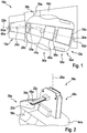
- FIG. 3 shows a detailed view of the mating contact unit 28a, which is arranged according to the first embodiment of the service robot system 10a on the service robot 12a.
- the at least two mating contact elements 32a, 34a of the mating contact unit 28a are, viewed in a plane extending at least substantially perpendicular to the vertical axis 26a of the base station 16a, a horizontal plane.
- the at least two mating contact elements 32a, 34a are provided during a charging process to the at least two flat contact charging elements 18a, 20a to lie.
- the at least two mating contact elements 32a, 34a have, in order to enable a loading docking process of the service robot 12a on the base station 16a in an angular range of at least more than 15 ° along a direction extending at least substantially transversely to an insertion direction, a greatest areal extent.
- the insertion direction corresponds to a direction along which the at least two flat contact charging elements 18a, 20a can be introduced into the mating contact unit 28a.
- the at least two mating contact elements 32a, 34a are in this case designed as sheet metal contact elements, in particular as copper sheet contact elements. However, it is also conceivable for the at least two mating contact elements 32a, 34a to have another configuration which appears expedient to a person skilled in the art.
- the at least two mating contact elements 32a, 34a viewed along a direction extending at least substantially parallel to the vertical axis 26a of the base station 16a, are arranged on each inner side of the mating contact unit 28a.
- the at least two mating contact elements 32a, 34a viewed along the at least substantially parallel to the vertical axis 26a of the base station 16a extending direction, disposed on two opposite sides of the mating contact unit 28a.
- one of the at least two mating contact elements 32a, 34a is formed as a positive electrical pole and one of the at least two mating contact elements 32a, 34a is formed as a negative electrical pole.
- the at least two flat contact charging elements 18a, 20a can be inserted to produce an electrical contact between the at least two mating contact elements 32a, 34a ( Figures 2 and 4 ).
- the at least two flat contact charging elements 18a, 20a each contact only one of the at least two mating contact elements 32a, 34a on one side.
- the service robot system 10a has at least one insulator element 36a, which is arranged between the at least two flat contact charging elements 18a, 20a and at least partly bears against the at least two flat contact charging elements 18a, 20a ( Figures 2 and 4 ).
- the insulator element 36a extends at least along one direction beyond at least one of the at least two flat contact charging elements 18a, 20a. This extends the Insulator element 36a at least along a direction at least substantially perpendicular to the vertical axis 26a of the base station 16a direction over the at least two flat contact charging elements 18a, 20a addition.
- a contact of the at least two flat contact charging elements 18a, 20a with a rigid electrically conductive component can advantageously be avoided at least as far as possible.
- a risk of short circuit can be advantageously kept low.
- the service robot system 10a has at least one position holding unit 38a (FIG. FIG. 1 ), which is intended to hold the service robot 12a at least in a loading position relative to the base station 16a.
- the position holding unit 38a comprises at least one position holding element 58a (FIG. FIG. 1 ).
- the position-retaining element 58a is in this case formed as a recess, in particular as a depression, in a base plate 64a of the base station 16a, in which at least one wheel of the chassis unit 54a can be arranged in a loading position of the service robot 12a.
- the service robot 12a is durable at least in a loading position relative to the base station 16a, at least by means of a positive connection between at least one wheel of the chassis unit 54a and the bottom plate 64a of the base station 16a.
- the position holding member 58a another, a person skilled in the appear appropriate design, such as a configuration as a magnetic element (permanent or electromagnet), as a mechanical locking element o. The like.
- a correct height alignment of the at least two flat contact charging elements 18a, 20a relative to the at least two mating contact elements 32a, 34a can be achieved.
- the service robot 12a drives at least partially onto the bottom plate 64a of the base station 16a during a docking process.
- a correct height alignment of the at least two flat contact charging elements 18a, 20a relative to the at least two mating contact elements 32a, 34a is advantageously achievable even on an uneven ground on which the base station 16a can be arranged.
- the bottom plate 64a of the base station 16a may further comprise at least one sub-base fastener (not shown in detail herein), such as a spike or peg.
- a safer State of the base station 16a can be achieved. It can thus be advantageously at least largely avoided movement of the base station 16a, such as due to a driving of the bottom plate 64a of the base station 16a by the service robot 12a, relative to a substrate.
- a risk of tipping and / or a risk of rotation of the base station 16a can be kept low.
- the service robot system 10a can be operated with a safe voltage, for example by means of a protective extra-low voltage.
- a safe voltage is applied to the at least two flat contact charging elements 18a, 20a and / or to the at least two mating contact elements 32a, 34a only in a non-charging state and upon detection of a correct contacting of the at least two flat contact charging elements 18a, 20a and at least two mating contact elements 32a, 34a bears a higher charging voltage to the at least two flat contact charging elements 18a, 20a and to the at least two mating contact elements 32a, 34a.
- the detection of a correct contacting and / or a release of a charging voltage can here by means of an electrical communication, by means of a radio communication, such as RFID, NFC o. The like., By means of a magnetic coding, by means of an optical coding (camera, Sensor o. The like.), By means of a mechanical coding o. The like.
- the service robot system 10a has at least one data logger unit 44a (FIG. FIG. 1 ), which is intended to log and evaluate at least one load parameter of at least two different service robots 12a.
- the data logger unit 44a is designed to log at least one charge parameter, in particular a flowing current, during a charging process.
- the data logger unit 44a is arranged on the service robot 12a.
- the logged by means of the data logger 44a Charge parameters are transferable by means of a powerline communication via the at least two flat contact charging elements 18a, 20a and via the at least two mating contact elements 32a, 34a or by means of a communication unit, in particular a wireless communication unit, to the base station 16a or to an external readout device (not shown in detail here) ,
- a communication unit in particular a wireless communication unit
- the powerline communication it is conceivable that different service robots 12a different frequencies or codes can be assigned to differentiate. Thus, for example, it can advantageously be detected which service robot 12a consumes how much power.
- the base station 16a comprises at least one auxiliary fueling unit 46a, which is provided to refuel at least the service robot 12a in at least one state with at least one auxiliary substance.
- the auxiliary fuel filling unit 46a comprises at least one refueling element 60a which can be connected to a refueling nozzle 62a of the service robot 12a.
- the refueling nozzle 62a in this case has a funnel-shaped configuration.
- a maximum insertion opening width of the refueling nozzle 62a is at least three times greater than a maximum widthwise extent of the refueling member 60a.
- the auxiliary fueling unit 46a is arranged on one side of the base station 16a, which faces away from another side of the base station 16a on which the at least two flat contact charging elements 18a, 20a are arranged. However, it is also conceivable that the auxiliary fueling unit 46a is arranged on the further side of the base station 16a, on which the at least two flat contact charging elements 18a, 20a are arranged. Thus, in a state of the service robot 12a arranged at the base station 16a, a refueling of the service robot 12a with an auxiliary substance can take place and a simultaneous charging of the energy storage unit 14a can take place.
- FIGS. 5 to 13 Further embodiments of the invention are shown. The following descriptions and the drawings are essentially limited to the differences between the exemplary embodiments, with reference in principle to the same reference components, in particular with respect to components with the same reference numerals, to the drawings and / or the description of the other embodiments, in particular FIGS. 1 to 4 , can be referenced.
- To distinguish the embodiments of the letter a is the reference numerals of the embodiment in the FIGS. 1 to 4 readjusted.
- the letter a is replaced by the letters b to h.
- FIG. 5 shows a detailed view of an alternative embodiment of at least two flat contact charging elements 18b, 20b and a mating contact unit 28b of a service robot system 10b.
- the service robot system 10b on no physical insulator element, which is arranged between the at least two flat contact charging elements 18b, 20b.
- the at least two flat contact charging elements 18b, 20b when viewed along a direction extending at least substantially parallel to a vertical axis 26b of a base station 16b of the service robot system 10b, are arranged vertically offset from one another.
- an air gap is arranged between the at least two flat contact charging elements 18b, 20b.
- the at least two flat contact charging elements 18b, 20b viewed along the at least substantially parallel to the vertical axis 26b of the base station 16b extending direction, arranged relative to each other at a distance.
- the mating contact unit 28b has two contact receiving spaces for contacting the at least two flat contact charging elements 18b, 20b with mating contact elements 32b, 32b ', 34b, 34b' of the mating contact unit 28b, wherein at least one of the mating contact elements 32b, 32b ', 34b, 34b' in one of the Contact receiving rooms is arranged.
- the service robot system 10b are each arranged at least two mating contact elements 32b, 32b ', 34b, 34b' in one of the contact receiving spaces.
- at least two mating contact elements 32b, 32b ', 34b, 34b' has a positive electrical pole and a negative electrical pole of the mating contact unit 28b.
- one of the at least two flat contact charging elements 18b, 20b is arranged in a state in contact with the mating contact elements 32b, 32b ', 34b, 34b' between at least two of the mating contact elements 32b, 32b ', 34b, 34b'.
- at least partially shown service robot system 10b may be on the in FIGS. 1 to 4 shown service robot system 10a are referenced.
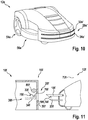
- FIG. 6 shows an alternative service robot system 10c with at least one service robot 12c, which includes at least one energy storage unit 14c, and at least one base station 16c at least to a power supply of the energy storage unit 14c in at least one state, the service robot 12c or the base station 16c at least two flat contact charging elements 18c, 20c having.
- the at least two flat contact charging elements 18c, 20c are arranged vertically offset from one another.
- the at least two FlachCountladeimplantation 18c, 20c disc-like are the at least two Flachtiveladeetti 18c, 20c disc-like.
- the at least two flat contact charging elements 18c, 20c viewed in a plane extending at least substantially perpendicular to a vertical axis 26c of the base station 16c, have a non-inventive annular configuration.
- the at least two flat contact charging elements 18c, 20c extend along a circumferential direction extending around the vertical axis 26c of the base station 16c at least more than 50% of a total circumferential extent of a partial area of the base station 16c around the partial area of the base station 16c.
- the at least two flat contact charging elements 18c, 20c extend at least completely around the partial area of the base station 16c along the circumferential direction running around the vertical axis 26c of the base station 16c.
- the base station 16c in this case has a circular-cylindrical configuration.
- the service robot system 10c comprises at least one contact touch protection unit 40c, which has at least one movably mounted contact contact protection element 42c, which is provided to at least one of the at least cover two flat contact charging elements 18c, 20c in at least one state.
- the contact contact protection element 42c is movably mounted on the base station 16c.
- the contact contact protection element 42c is mounted in a translationally movable manner on the base station 16c, in particular along a direction extending at least substantially perpendicular to the vertical axis 26c of the base station 16c.
- Theêtberckenstoffschutzelement 42c has a hollow circular cylindrical configuration.
- the contact contact protection element 42c has at least one passage opening 66c, which is provided to enable and / or engage the at least two flat contact charging elements 18c, 20c through the contact contact protection element 42c as a result of a movement of the contact contact protection element 42c relative to the at least two flat contact charging elements 18c, 20c Extending the at least two flat contact charging elements 18c, 20c over the contact contact protection element 42c.
- the contact touch protection element 42c is movable at the base station 16c due to a charge docking process of the service robot 12c. In this case, the contact contact protection element 42c is translationally movable as a result of a direct contact of the service robot 12c and of the contact contact protection element 42c.
- the contact contact protection unit 40c may have at least one actuator element for a movement of the contact contact protection element 42c, wherein the actuator element moves the contact contact protection element 42c as a result of communication between the service robot 12c and the base station 16c.
- the contact contact protection unit 40c comprises at least one reset element 68c (FIG. FIG. 7 ), which is intended to automatically move the contact contact protection element 42c to a cover position, in particular after the service robot 12c has left its loading position.
- the at least two flat contact charging elements 18c, 20c are arranged completely within the contact-contact protection element 42c.
- the restoring element 68c is in this case designed as a spring-loaded centering cone which is movably mounted along a direction extending at least substantially parallel to the vertical axis 26c of the base station 16c, in particular mounted in a translationally movable manner.
- the restoring element 68c has another configuration and / or arrangement which appears expedient to a person skilled in the art.
- the return element 68c can also by means of another Actuator element of Kunststoffbermmstofftechniktician 40c be acted upon, wherein the further actuator element is provided to limit a movement possibility of the restoring element 68c and thus the Kunststoffberlickschutzelements 42c or avoid.
- the further actuator element only releases a movement possibility of the contact contact protection element 42c after the release of a release code from the service robot 12c to the base station 16c.
- an unauthorized charging process can be prevented.
- FIGS. 6 and 7 displayed service robot system 10c may on the in the FIGS. 1 to 4 shown service robot system 10a are referenced.
- FIG. 8 shows a detailed view of an alternative embodiment of at least two flat contact charging elements 18d, 20d and a mating contact unit 28d of a service robot system 10d.
- the service robot system 10d the at least two flat contact charging elements 18d, 20d, which are mounted relative to each other movable.
- the at least two flat contact charging elements 18d, 20d are connected to one another by means of at least one joint element 70d of the service robot system 10d.
- the at least two flat contact charging elements 18d, 20d have a non-inventive semicircular design.
- the at least two flat contact charging elements 18d, 20d are provided to at least partially surround the mating contact unit 28d.
- the mating contact unit 28d has a circular-cylindrical configuration.
- the mating contact unit 28d which is provided for receiving at least one of the at least two flat contact charging elements 18d, 20d, extends over at least an angular range of more than 30 °.
- the mating contact unit 28d extends at least over an angular range of more than 180 °, preferably over an angular range of more than 270 ° and particularly preferably over an angular range of more than 300 °.
- the mating contact unit 28d is disposed on an outside of a base station 16d of the service robot system 10d.
- the base station 16d also has a circular cylindrical configuration.
- the service robot system 10d has at least one actuator element (not shown here in detail) for a movement of the at least two flat contact charging elements 18d, 20d relative to each other.
- a position holding unit 38d of the service robot system 10d can be realized thereby.
- an anti-theft function can be realized, wherein the at least two flat contact charging elements 18d, 20d are again movable relative to each other after embracing the mating contact unit 28d, for example only after an input of a security code.
- FIG. 8 at least partially shown service robot system 10d may on the in the FIGS. 1 to 4 shown service robot system 10a are referenced.
- FIG. 9 shows another alternative service robot system 10e with at least one service robot 12e, which comprises at least one energy storage unit 14e, and at least one base station 16e at least for energy supply of the energy storage unit 14e in at least one state, wherein the service robot 12e or the base station 16e at least two flat contact charging elements 18e, 20e.
- the at least two flat contact charging elements 18e, 20e are plate-like.
- the at least two flat contact charging elements 18e, 20e viewed in a plane extending at least substantially perpendicularly to a vertical axis 26e of the base station 16e, have a non-inventive elliptical-sector-like configuration.
- an arcuate part of the at least two flat contact charging elements 18e, 20e, which are configured ellipsoid-like is assigned to a longest side of the base station 16e.
- the base station 16e has, viewed in the at least substantially perpendicular to the vertical axis 26e of the base station 16e extending plane, a polygonal, in particular rectangular, configuration.
- the service robot system 10e may in this case comprise a contact contact protection unit (not shown here in greater detail), which has an at least substantially analogous configuration to that in FIGS. 6 and 7 has shown Maisberlickschutzaku 40c.
- the service robot 12e has a mating contact unit 28e for receiving and / or contacting the at least two flat contact charging elements 18e, 20e.
- the mating contact unit 28e has a plurality of mating contact elements 32e, 34e, which are arranged on a front side of the service robot 12e.
- the mating contact elements 32e, 34e are distributed uniformly at least over an angular range of more than 30 ° at the front of the service robot 12e. However, it is also conceivable that the mating contact elements 32e, 34e are arranged unevenly distributed at least over an angular range of more than 30 ° at the front of the service robot 12e. The mating contact unit 28e thus extends at least over an angular range of more than 30 ° on the service robot 12e.
- FIG. 10 shows a detailed view of the service robot 12e of in FIG. 9 shown service robot system 10e with an alternative embodiment of a mating contact unit 28e '.
- the mating contact unit 28e ' in this case comprises at least two mating contact elements 32e', 34e ', which are arranged in a circular arc on the service robot 12e, in particular on a front side of the service robot 12e.
- the at least two mating contact elements 32e ', 34e' extend at least over an angular range of more than 45 ° on the service robot 12e, in particular on a front side of the service robot 12e.
- the mating contact unit 28e ' forms slot-shaped receptacles for the at least two flat contact charging elements 18e, 20e.
- FIGS. 1 to 4 shown service robot system 10a are referenced.
- FIG. 11 shows another alternative service robot system 10f with at least one service robot 12f, which comprises at least one energy storage unit 14f, and at least one base station 16f at least for energy supply of the energy storage unit 14f in at least one state, the service robot 12f or the base station 16f at least two flat contact charging elements 18f, 20f.
- the service robot 12f has the at least two flat contact charging elements 18f, 20f.
- the at least two flat contact charging elements 18f, 20f are formed like a tongue.
- the at least two flat contact charging elements 18f, 20f are mounted so as to be movable relative to one another.
- a movement axis of at least one of the at least two flat contact charging elements 18f, 20f in this case runs at least substantially perpendicular to a vertical axis 72f of the service robot 12f.
- the service robot system 10f comprises at least one position-holding unit 38f, which is provided to hold the service robot 12f at least in a loading position relative to the base station 16f.
- the position holding unit 38f comprises at least one latching element 74f for this purpose.
- the locking element 74f is designed as a latching hook.
- the latching element 74f is integrally formed with one of the at least two flat contact charging elements 18f, 20f, in particular with the movably mounted flat contact charging element 18f.
- the detent member 74f forms a position holding member 58f of the position holding unit 38f.
- the latching element 74f is arranged on a side remote from the service robot 12f on one of the at least two flat contact charging elements 18f, 20f.
- the latching element 74f is provided to cooperate with a corresponding to the latching element 74f counter-detent element 76f of the position holding unit 38f to hold the Serviceroboters 12f at least in a loading position relative to the base station 16f, in particular by means of a positive and / or non-positive connection.
- the counter-latching element 76f is arranged at the base station 16f for this purpose.
- the counter-latching element 76f is arranged on a mating contact element 32f of a mating contact unit 28f of the service robot system 10f.
- the latching element 74f can be brought into engagement with the counter-latching element 76f when contacting the at least two flat contact charging elements 18f, 20f with the mating contact unit 28f.
- the movably mounted flat contact charging element 18f is deflected upon insertion into an insertion opening 30f of the mating contact unit 28f as a result of an interaction of an inclined surface of the locking element 74f with the mating locking element 76f.
- the at least two flat contact charging elements 18f, 20f are moved into the mating contact unit 28f until the latching element 74f engages in the counter-latching element 76f.
- a movement of the service robot 12f in a direction away from the base station 16f direction is thus prevented as a result of engagement of the locking element 74f in the counter-locking element 76f.
- the movably mounted flat contact charging element 18f can be brought into contact with an unlocking element 78f of the position holding unit 38f.
- the movably mounted flat contact charging element 18f is again deflectable.
- the position holding unit 38f has at least one deflection retaining element 80f.
- the Auslenkhalteelement 80f may be formed here as an electromagnet or as a permanent magnet.
- the position holding unit 38f comprises at least one actuator element which is provided for automatically deflecting the movably mounted flat contact charging element 18f, in particular after a termination of a charging process.
- the actuator element can in this case be arranged on the service robot 12f or on the base station 16f.
- FIG. 11 shown service robot system 10f may on the in the FIGS. 1 to 4 shown service robot system 10a are referenced.
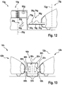
- FIG. 12 shows another alternative service robot system 10g with at least one service robot 12g, which includes at least one energy storage unit 14g, and at least one base station 16g at least to a power supply of the energy storage unit 14g in at least one state, wherein the service robot 12g or the base station 16g at least two flat contact charging elements 18g, 20g.
- the at least two flat contact charging elements 18g, 20g are formed like a tongue.
- the service robot system 10g comprises at least one position holding unit 38g, which is provided to hold the service robot 12g at least in a loading position relative to the base station 16g.
- the position holding unit 38g comprises at least one latching element 74g for this purpose.
- the locking element 74g is designed as a latching hook.
- the latching element 74g is integrally formed with one of the at least two flat contact charging elements 18g, 20g.
- forms the latching member 74g is a position holding member 58g of the position holding unit 38g.
- the latching element 74g is arranged on a side facing away from the service robot 12g on one of the at least two flat contact charging elements 18g, 20g.
- the latching element 74g is intended to cooperate with a corresponding to the latching element 74g formed counter-latching element 76g of the position holding unit 38g to hold the service robot 12g at least in a loading position relative to the base station 16g, in particular by means of a positive and / or non-positive connection.
- the counter-latching element 76g is arranged on the base station 16g for this purpose.
- the counter-latching element 76g is movably mounted on the base station 16g.
- the counter-latching element 76g is mounted in a translationally movable manner, in particular along a direction extending at least substantially parallel to a vertical axis 26g of the base station 16g.
- the counter-latching element 76g is in this case provided to cover an insertion opening 30g of a mating contact unit 28g at least to a large extent and / or to close it.
- the latching element 74g can be brought into engagement with the counter-latching element 76g when contacting the at least two flat contact charging elements 18g, 20g with the mating contact unit 28g.
- the at least two flat contact charging elements 18g, 20g are introduced into the mating contact unit 28g.
- the latching element 74g comprises at least one inclined surface for a movement of the counter-latching element 76g and for a release of the insertion opening 30g. The inclined surface moves the counter-latching element 76g due to an interaction of the inclined surface and the counter-latching element 76g in a direction extending at least substantially transversely to an insertion direction.
- the counter-latching element 76g is also acted upon by means of a spring element of the position-holding unit 38g in the direction of the latching element 74g with a force.
- the at least two flat contact charging elements 18g, 20g are moved into the mating contact unit 28g until a engagement of the counter-latching element 76g takes place in a latching recess of the latching element 74g, in particular due to a force of the spring element.
- a movement of the service robot 12g in a direction away from the base station 16g direction is thus prevented as a result of engagement of the counter-latching element 76g in the latching recess of the latching element 74g.
- the position-holding unit 38g has at least one deflection-holding element 80g.
- the Auslenkhalteelement 80g is formed here as an electromagnet. After a detection of a state of the at least two flat contact charging elements 18g, 20g which has moved completely out of the mating contact unit 28g, the deflection retaining element 80g releases the counter-locking element 76g again. The counter-latching element 76g is thus again movable by means of the spring element into an initial position.
- the position holding unit 38g comprises at least one actuator element which is provided to automatically deflect the counter-latching element 76g, in particular after a termination of a charging process.
- the actuator element may in this case be arranged on the service robot 12g or on the base station 16g.
- FIG. 12 shown service robot system 10g may on the in the FIGS. 1 to 4 shown service robot system 10a are referenced.
- FIG. 13 shows another alternative service robot system 10h with at least one service robot 12h, which comprises at least one energy storage unit 14h, and at least one base station 16h at least for energy supply of the energy storage unit 14h in at least one state, the service robot 12h or the base station 16h at least two flat contact charging elements 18h, 20h.
- the at least two flat contact charging elements 18h, 20h are tongue-like.
- the at least two flat contact charging elements 18h, 20h are provided for contacting at least two mating contact elements 32h, 34h of a mating contact unit 28h.
- the at least two mating contact elements 32h, 34h are arranged here at the base station 16h.
- the service robot system 10h comprises at least one further service robot 82h, which comprises at least two flat contact charging elements 84h, 86h.
- the at least two flat contact charging elements 84h, 86h of the further service robot 82h are provided to cooperate with at least one of the at least two mating contact elements 32h, 34h and at least one further mating contact element 88h of the mating contact unit 28h.
- the further mating contact element 88h is likewise arranged on the base station 16h.
- the further counter contact element 88h is designed as a positive electrical pole for the further service robot 82h.
- the mating contact element 32h which is provided for contacting with at least one flat contact charging element 84h of the further service robot 82h and with at least one flat contact charging element 18h of the service robot 12h, is designed as a negative electrical pole.
- the negative contact pole formed as a negative contact element 32h for the service robot 12h and the other service robot 82h is arranged in a plane.
- the mating contact element 34h which is designed as a positive electrical pole for at least one of the at least two flat contact charging elements 18h, 20h of the service robot 12h, is spaced, viewed along a direction at least substantially parallel to a vertical axis 26h of the base station 16h, relative to the further mating contact element 88h arranged.
- FIG. 13 shown service robot system 10h may on the in the FIGS. 1 to 4 shown service robot system 10a are referenced.
Landscapes
- Engineering & Computer Science (AREA)
- Power Engineering (AREA)
- Transportation (AREA)
- Mechanical Engineering (AREA)
- Aviation & Aerospace Engineering (AREA)
- Radar, Positioning & Navigation (AREA)
- Remote Sensing (AREA)
- Physics & Mathematics (AREA)
- General Physics & Mathematics (AREA)
- Automation & Control Theory (AREA)
- Manipulator (AREA)
- Electric Vacuum Cleaner (AREA)
- Charge And Discharge Circuits For Batteries Or The Like (AREA)
Claims (12)
- Système de tondeuse à gazon comprenant au moins une tondeuse à gazon autonome qui comprend au moins une unité de stockage d'énergie (14a ; 14c ; 14e), et au moins une station de base au moins pour une alimentation en énergie de l'unité de stockage d'énergie (14a ; 14c ; 14e) dans au moins un état, la tondeuse à gazon autonome ou la station de base présentant au moins deux éléments de charge à contacts plats (18a, 20a ; 18b, 20b ; 18c, 20c ; 18d, 20d ; 18e, 20e ; 18f, 20f ; 18g, 20g ; 18h, 20h), les au moins deux éléments de charge à contacts plats étant prévus pour permettre un processus d'ancrage de charge de la tondeuse à gazon autonome à la station de base dans une plage angulaire supérieure à 15°, la plage angulaire s'étendant à partir d'un axe longitudinal d'au moins l'un des au moins deux éléments de charge à contacts plats, à chaque fois 50 % de la plage angulaire s'étendant à partir de l'axe longitudinal dans deux directions opposées, caractérisé par au moins une unité de libération qui est prévue pour libérer au moins une tension de charge maximale dans au moins une position de charge de la tondeuse à gazon autonome par rapport à la station de base en fonction d'au moins une grandeur caractéristique, et à cet effet, la tondeuse à gazon autonome et la station de base comprenant à chaque fois au moins une unité de communication sans fil qui est prévue pour un transfert bidirectionnel de données électroniques ou de signaux numériques.
- Système de tondeuse à gazon selon la revendication 1, caractérisé en ce que le processus d'ancrage de charge de la tondeuse à gazon autonome par rapport à un axe central (22a ; 22c ; 22e) de la station de base peut être réalisé dans une plage angulaire d'au moins ± 7,5° par rapport à un axe médian (24a ; 24c ; 24e) de la tondeuse à gazon autonome robot de service.
- Système de tondeuse à gazon selon la revendication 1 ou 2, caractérisé en ce que les au moins deux éléments de charge à contacts plats (18a, 20a ; 18b, 20b ; 18c, 20c ; 18d, 20d ; 18e, 20e ; 18f, 20f ; 18g, 20g ; 18h, 20h) sont disposés de manière décalée verticalement l'un par rapport à l'autre.
- Système de tondeuse à gazon selon l'une quelconque des revendications précédentes, caractérisé en ce que les au moins deux éléments de charge à contacts plats (18a, 20a ; 18b, 20b ; 18c, 20c ; 18d, 20d ; 18e, 20e ; 18f, 20f ; 18g, 20g ; 18h, 20h), vu le long d'un axe vertical (26a ; 26b ; 26c ; 26d ; 26e ; 72f ; 72g ; 72h) de la tondeuse à gazon autonome ou de la station de base sont disposés au moins essentiellement en affleurement l'un avec l'autre.
- Système de tondeuse à gazon selon l'une quelconque des revendications précédentes, caractérisé en ce que les au moins deux éléments de charge à contacts plats (18a, 20a ; 18b, 20b ; 18c, 20c ; 18d, 20d ; 18e, 20e ; 18f, 20f ; 18g, 20g ; 18h, 20h) sont réalisés en forme de plaque ou de langue.
- Système de tondeuse à gazon selon l'une quelconque des revendications précédentes, caractérisé par au moins une unité de contact conjuguée (28a ; 28b ; 28c ; 28d ; 28e ; 28f ; 28g ; 28h) qui est prévue pour recevoir au moins l'un des au moins deux éléments de charge à contacts plats (18a, 20a ; 18b, 20b ; 18c, 20c ; 18d, 20d ; 18e, 20e ; 18f, 20f ; 18g, 20g ; 18h, 20h) et qui est configurée de telle sorte que le processus d'ancrage de charge de la tondeuse à gazon autonome par rapport à l'axe central (22a ; 22c ; 22e) de la station de base soit possible dans une plage angulaire d'au moins ± 7,5° par rapport à l'axe médian (24a ; 24c ; 24e) de la tondeuse à gazon autonome.
- Système de tondeuse à gazon selon l'une quelconque des revendications précédentes, caractérisé par au moins une unité de contact conjuguée (28a ; 28b ; 28c ; 28d ; 28e ; 28f ; 28g ; 28h) qui est prévue pour recevoir au moins l'un des au moins deux éléments de charge à contacts plats (18a, 20a ; 18b, 20b ; 18c, 20c ; 18d, 20d ; 18e, 20e ; 18f, 20f ; 18g, 20g ; 18h, 20h) et qui présente une ouverture d'introduction (30a ; 30b ; 30c ; 30d ; 30e ; 30f ; 30g ; 30h) qui présentent une étendue minimale en largeur qui correspond au moins au triple d'une étendue maximale en largeur de l'un des au moins deux éléments de charge à contacts plats (18a, 20a ; 18b, 20b ; 18c, 20c ; 18d, 20d ; 18e, 20e ; 18f, 20f ; 18g, 20g ; 18h, 20h) .
- Système de tondeuse à gazon selon l'une quelconque des revendications précédentes, caractérisé par au moins une unité de contact conjuguée (28a ; 28b ; 28c ; 28d ; 28e ; 28f ; 28g ; 28h) qui présente au moins un élément de contact conjugué (32a, 34a ; 32b, 34b ; 32c, 34c ; 32d, 34d ; 32e, 34e ; 32f, 34f ; 32g, 34g ; 32h, 34h) qui, considéré dans un plan horizontal s'étendant au moins essentiellement perpendiculairement à un axe vertical (26a ; 26b ; 26c ; 26d ; 26e ; 72f ; 72g ; 72h) de la tondeuse à gazon autonome ou de la station de base, est réalisé sous forme plate.
- Système de tondeuse à gazon selon l'une quelconque des revendications précédentes, caractérisé par au moins une unité de contact conjuguée (28d ; 28e ; 28e') qui est prévue pour recevoir au moins l'un des au moins deux éléments de charge à contacts plats (18d, 20d ; 18e, 20e) et qui s'étend au moins sur une plage angulaire supérieure à 30°.
- Système de tondeuse à gazon selon l'une quelconque des revendications précédentes, caractérisé en ce que les au moins deux éléments de charge à contacts plats (18d, 20d ; 18f, 20f ; 18g, 20g) sont supportés de manière déplaçable les uns par rapport aux autres.
- Tondeuse à gazon autonome d'un système de tondeuse à gazon selon l'une quelconque des revendications précédentes.
- Station de base d'un système de tondeuse à gazon selon l'une quelconque des revendications 1 à 10.
Applications Claiming Priority (1)
| Application Number | Priority Date | Filing Date | Title |
|---|---|---|---|
| DE102014212427.1A DE102014212427A1 (de) | 2014-06-27 | 2014-06-27 | Servicerobotersystem |
Publications (3)
| Publication Number | Publication Date |
|---|---|
| EP2960100A2 EP2960100A2 (fr) | 2015-12-30 |
| EP2960100A3 EP2960100A3 (fr) | 2016-04-06 |
| EP2960100B1 true EP2960100B1 (fr) | 2019-08-07 |
Family
ID=53496386
Family Applications (1)
| Application Number | Title | Priority Date | Filing Date |
|---|---|---|---|
| EP15170834.4A Active EP2960100B1 (fr) | 2014-06-27 | 2015-06-05 | Système de robot de service |
Country Status (2)
| Country | Link |
|---|---|
| EP (1) | EP2960100B1 (fr) |
| DE (1) | DE102014212427A1 (fr) |
Cited By (11)
| Publication number | Priority date | Publication date | Assignee | Title |
|---|---|---|---|---|
| EP4083741A1 (fr) | 2021-04-30 | 2022-11-02 | Husqvarna Ab | Procédé et système de chargement d'un outil de travail robotique |
| EP4328077A1 (fr) * | 2022-04-25 | 2024-02-28 | Techtronic Cordless GP | Outil robotique et station de charge |
| US12296694B2 (en) | 2021-03-10 | 2025-05-13 | Techtronic Cordless Gp | Lawnmowers |
| US12369509B2 (en) | 2022-07-19 | 2025-07-29 | Techtronic Cordless Gp | Display for controlling robotic tool |
| US12425197B2 (en) | 2022-07-29 | 2025-09-23 | Techtronic Cordless Gp | Generation of a cryptography key for a robotic garden tool |
| US12443180B2 (en) | 2021-11-10 | 2025-10-14 | Techtronic Cordless Gp | Robotic lawn mowers |
| US12472611B2 (en) | 2022-05-31 | 2025-11-18 | Techtronic Cordless Gp | Peg driver |
| US12510892B2 (en) | 2022-04-28 | 2025-12-30 | Techtronic Cordless Gp | Creation of a virtual boundary for a robotic garden tool |
| US12564130B2 (en) | 2022-01-31 | 2026-03-03 | Techtronic Cordless Gp | Robotic garden tool |
| USD1118706S1 (en) | 2025-01-07 | 2026-03-17 | Techtronic Cordless Gp | Lawnmower housing |
| USD1118709S1 (en) | 2025-01-07 | 2026-03-17 | Techtronic Cordless Gp | Electric lawnmower charging port |
Families Citing this family (7)
| Publication number | Priority date | Publication date | Assignee | Title |
|---|---|---|---|---|
| US11172605B2 (en) | 2016-06-30 | 2021-11-16 | Tti (Macao Commercial Offshore) Limited | Autonomous lawn mower and a system for navigating thereof |
| EP3533310B1 (fr) * | 2018-02-28 | 2020-07-01 | Honda Motor Co., Ltd. | Système de gestion de terrain de pelouse |
| US10644519B2 (en) * | 2018-05-30 | 2020-05-05 | Amazon Technologies, Inc. | Positionally compliant charge connector for robotic drive unit charging |
| JP7444460B2 (ja) * | 2018-12-03 | 2024-03-06 | Groove X株式会社 | ロボット用充電ステーション |
| CN112134329A (zh) * | 2020-09-24 | 2020-12-25 | 广东杜尼智能机器人工程技术研究中心有限公司 | 一种被动式自动对准充电方法 |
| IT202000029933A1 (it) * | 2020-12-04 | 2022-06-04 | Stiga S P A In Breve Anche St S P A | Apparecchio autopropulso, in particolare dispositivo rasaerba a guida autonoma, e relativo dispositivo di ricarica, in particolare stazione di ricarica per dispositivo rasaerba a guida autonoma |
| AU2023202377A1 (en) * | 2022-04-22 | 2023-11-09 | Techtronic Cordless Gp | Robotic tool and charging station |
Citations (1)
| Publication number | Priority date | Publication date | Assignee | Title |
|---|---|---|---|---|
| WO2000074465A1 (fr) * | 1999-06-03 | 2000-12-14 | Robert William Chandler | Machine de tonte automatisee |
Family Cites Families (7)
| Publication number | Priority date | Publication date | Assignee | Title |
|---|---|---|---|---|
| FR2828589B1 (fr) * | 2001-08-07 | 2003-12-05 | France Telecom | Systeme de connexion electrique entre un vehicule et une station de recharge ou similaire |
| KR100480036B1 (ko) * | 2002-12-17 | 2005-03-31 | 엘지전자 주식회사 | 자동 주행 청소기의 자동 충전 장치 및 방법 |
| KR100820743B1 (ko) * | 2003-10-21 | 2008-04-10 | 삼성전자주식회사 | 이동 로봇의 충전 장치 |
| CH701209A1 (de) * | 2009-06-03 | 2010-12-15 | Plantcare Ag | Mobile vorrichtung und verfahren zur bedarfsgerechten bewässerung eines bodens. |
| FR2961026B1 (fr) * | 2010-06-07 | 2015-04-17 | Multi Holding Ag | Element male de raccordement electrique, vehicule et station de recharge comportant un tel element male, et ensemble de raccordement electrique |
| DE102011084594A1 (de) * | 2011-10-17 | 2013-04-18 | Robert Bosch Gmbh | Autonomes Arbeitsgerät |
| PL2717109T3 (pl) * | 2012-10-04 | 2016-01-29 | Viking Gmbh | Urządzenie do ładowania samobieżnego narzędzia pracy |
-
2014
- 2014-06-27 DE DE102014212427.1A patent/DE102014212427A1/de not_active Withdrawn
-
2015
- 2015-06-05 EP EP15170834.4A patent/EP2960100B1/fr active Active
Patent Citations (1)
| Publication number | Priority date | Publication date | Assignee | Title |
|---|---|---|---|---|
| WO2000074465A1 (fr) * | 1999-06-03 | 2000-12-14 | Robert William Chandler | Machine de tonte automatisee |
Cited By (11)
| Publication number | Priority date | Publication date | Assignee | Title |
|---|---|---|---|---|
| US12296694B2 (en) | 2021-03-10 | 2025-05-13 | Techtronic Cordless Gp | Lawnmowers |
| EP4083741A1 (fr) | 2021-04-30 | 2022-11-02 | Husqvarna Ab | Procédé et système de chargement d'un outil de travail robotique |
| US12443180B2 (en) | 2021-11-10 | 2025-10-14 | Techtronic Cordless Gp | Robotic lawn mowers |
| US12564130B2 (en) | 2022-01-31 | 2026-03-03 | Techtronic Cordless Gp | Robotic garden tool |
| EP4328077A1 (fr) * | 2022-04-25 | 2024-02-28 | Techtronic Cordless GP | Outil robotique et station de charge |
| US12510892B2 (en) | 2022-04-28 | 2025-12-30 | Techtronic Cordless Gp | Creation of a virtual boundary for a robotic garden tool |
| US12472611B2 (en) | 2022-05-31 | 2025-11-18 | Techtronic Cordless Gp | Peg driver |
| US12369509B2 (en) | 2022-07-19 | 2025-07-29 | Techtronic Cordless Gp | Display for controlling robotic tool |
| US12425197B2 (en) | 2022-07-29 | 2025-09-23 | Techtronic Cordless Gp | Generation of a cryptography key for a robotic garden tool |
| USD1118706S1 (en) | 2025-01-07 | 2026-03-17 | Techtronic Cordless Gp | Lawnmower housing |
| USD1118709S1 (en) | 2025-01-07 | 2026-03-17 | Techtronic Cordless Gp | Electric lawnmower charging port |
Also Published As
| Publication number | Publication date |
|---|---|
| EP2960100A2 (fr) | 2015-12-30 |
| EP2960100A3 (fr) | 2016-04-06 |
| DE102014212427A1 (de) | 2016-01-14 |
Similar Documents
| Publication | Publication Date | Title |
|---|---|---|
| EP2960100B1 (fr) | Système de robot de service | |
| EP2223782B1 (fr) | Batterie pour un outil électrique | |
| EP3774437B1 (fr) | Véhicule automobile pourvu d'une unité de mise en contact électrique | |
| DE102016221829B4 (de) | Energieversorgungsfahrzeug zum Versorgen eines elektrisch antreibbaren Kraftfahrzeugs mit elektrischer Energie | |
| EP2936519B1 (fr) | Accumulateur d'outil portatif | |
| EP2423152B1 (fr) | Chariot de manutention doté d'un espace de réception de batterie | |
| EP3092147B1 (fr) | Dispositif de charge électrique, dispositif de connexion électrique, système et procédé à charger une batterie de véhicule | |
| EP3451888B1 (fr) | Système de traitement des sols | |
| EP2819207B1 (fr) | Combinaison d'un système de support, d'une batterie et d'un appareil à entraîner | |
| EP2717109B1 (fr) | Dispositif de chargement pour un appareil de travail autopropulsé | |
| EP3642892B1 (fr) | Dispositif interface de bloc-batterie | |
| EP4010218A1 (fr) | Système de charge, appareil de charge, dispositif mobile et partie d'insertion pour un dispositif mobile | |
| DE102009027557A1 (de) | Modulare Arbeitsvorrichtung | |
| DE102017211006A1 (de) | Tragbare Ladevorrichtung | |
| WO2021089713A1 (fr) | Robot modulaire | |
| DE102013219444A1 (de) | Ladeeinrichtung zum induktiven Laden | |
| WO2018077683A1 (fr) | Dispositif de connexion d'un appareil électrique ou d'un accumulateur d'énergie | |
| WO2019063212A1 (fr) | Bloc-batterie | |
| DE102012112887A1 (de) | System | |
| EP2323197A2 (fr) | Batterie dotée d'un dispositif de retenue | |
| WO2011029663A2 (fr) | Moyen de charge d'accumulateur pour outil à main | |
| WO2015036154A1 (fr) | Dispositif de charge, dispositif de réception, système et procédé de charge d'une batterie par induction | |
| DE19614199C1 (de) | Arbeitsgerät mit einem batteriebetriebenen Elektromotor | |
| WO2020089381A1 (fr) | Dispositif et procédé de charge par conduction | |
| DE102016100609A1 (de) | Ladesystem und Ladesteckverbinder dafür |
Legal Events
| Date | Code | Title | Description |
|---|---|---|---|
| PUAI | Public reference made under article 153(3) epc to a published international application that has entered the european phase |
Free format text: ORIGINAL CODE: 0009012 |
|
| AK | Designated contracting states |
Kind code of ref document: A2 Designated state(s): AL AT BE BG CH CY CZ DE DK EE ES FI FR GB GR HR HU IE IS IT LI LT LU LV MC MK MT NL NO PL PT RO RS SE SI SK SM TR |
|
| AX | Request for extension of the european patent |
Extension state: BA ME |
|
| PUAL | Search report despatched |
Free format text: ORIGINAL CODE: 0009013 |
|
| AK | Designated contracting states |
Kind code of ref document: A3 Designated state(s): AL AT BE BG CH CY CZ DE DK EE ES FI FR GB GR HR HU IE IS IT LI LT LU LV MC MK MT NL NO PL PT RO RS SE SI SK SM TR |
|
| AX | Request for extension of the european patent |
Extension state: BA ME |
|
| RIC1 | Information provided on ipc code assigned before grant |
Ipc: B60L 11/18 20060101AFI20160229BHEP Ipc: H01R 13/631 20060101ALI20160229BHEP Ipc: G05D 1/02 20060101ALI20160229BHEP |
|
| 17P | Request for examination filed |
Effective date: 20161006 |
|
| RBV | Designated contracting states (corrected) |
Designated state(s): AL AT BE BG CH CY CZ DE DK EE ES FI FR GB GR HR HU IE IS IT LI LT LU LV MC MK MT NL NO PL PT RO RS SE SI SK SM TR |
|
| STAA | Information on the status of an ep patent application or granted ep patent |
Free format text: STATUS: EXAMINATION IS IN PROGRESS |
|
| 17Q | First examination report despatched |
Effective date: 20170321 |
|
| REG | Reference to a national code |
Ref country code: DE Ref legal event code: R079 Ref document number: 502015009865 Country of ref document: DE Free format text: PREVIOUS MAIN CLASS: B60L0011180000 Ipc: B60L0009000000 |
|
| GRAP | Despatch of communication of intention to grant a patent |
Free format text: ORIGINAL CODE: EPIDOSNIGR1 |
|
| STAA | Information on the status of an ep patent application or granted ep patent |
Free format text: STATUS: GRANT OF PATENT IS INTENDED |
|
| RIC1 | Information provided on ipc code assigned before grant |
Ipc: B60L 9/00 20190101AFI20190116BHEP |
|
| INTG | Intention to grant announced |
Effective date: 20190211 |
|
| GRAS | Grant fee paid |
Free format text: ORIGINAL CODE: EPIDOSNIGR3 |
|
| GRAA | (expected) grant |
Free format text: ORIGINAL CODE: 0009210 |
|
| STAA | Information on the status of an ep patent application or granted ep patent |
Free format text: STATUS: THE PATENT HAS BEEN GRANTED |
|
| AK | Designated contracting states |
Kind code of ref document: B1 Designated state(s): AL AT BE BG CH CY CZ DE DK EE ES FI FR GB GR HR HU IE IS IT LI LT LU LV MC MK MT NL NO PL PT RO RS SE SI SK SM TR |
|
| REG | Reference to a national code |
Ref country code: GB Ref legal event code: FG4D Free format text: NOT ENGLISH |
|
| REG | Reference to a national code |
Ref country code: CH Ref legal event code: EP Ref country code: AT Ref legal event code: REF Ref document number: 1163307 Country of ref document: AT Kind code of ref document: T Effective date: 20190815 |
|
| REG | Reference to a national code |
Ref country code: DE Ref legal event code: R096 Ref document number: 502015009865 Country of ref document: DE |
|
| REG | Reference to a national code |
Ref country code: IE Ref legal event code: FG4D Free format text: LANGUAGE OF EP DOCUMENT: GERMAN |
|
| REG | Reference to a national code |
Ref country code: NL Ref legal event code: MP Effective date: 20190807 |
|
| REG | Reference to a national code |
Ref country code: LT Ref legal event code: MG4D |
|
| PG25 | Lapsed in a contracting state [announced via postgrant information from national office to epo] |
Ref country code: SE Free format text: LAPSE BECAUSE OF FAILURE TO SUBMIT A TRANSLATION OF THE DESCRIPTION OR TO PAY THE FEE WITHIN THE PRESCRIBED TIME-LIMIT Effective date: 20190807 Ref country code: BG Free format text: LAPSE BECAUSE OF FAILURE TO SUBMIT A TRANSLATION OF THE DESCRIPTION OR TO PAY THE FEE WITHIN THE PRESCRIBED TIME-LIMIT Effective date: 20191107 Ref country code: NL Free format text: LAPSE BECAUSE OF FAILURE TO SUBMIT A TRANSLATION OF THE DESCRIPTION OR TO PAY THE FEE WITHIN THE PRESCRIBED TIME-LIMIT Effective date: 20190807 Ref country code: PT Free format text: LAPSE BECAUSE OF FAILURE TO SUBMIT A TRANSLATION OF THE DESCRIPTION OR TO PAY THE FEE WITHIN THE PRESCRIBED TIME-LIMIT Effective date: 20191209 Ref country code: HR Free format text: LAPSE BECAUSE OF FAILURE TO SUBMIT A TRANSLATION OF THE DESCRIPTION OR TO PAY THE FEE WITHIN THE PRESCRIBED TIME-LIMIT Effective date: 20190807 Ref country code: LT Free format text: LAPSE BECAUSE OF FAILURE TO SUBMIT A TRANSLATION OF THE DESCRIPTION OR TO PAY THE FEE WITHIN THE PRESCRIBED TIME-LIMIT Effective date: 20190807 Ref country code: FI Free format text: LAPSE BECAUSE OF FAILURE TO SUBMIT A TRANSLATION OF THE DESCRIPTION OR TO PAY THE FEE WITHIN THE PRESCRIBED TIME-LIMIT Effective date: 20190807 Ref country code: NO Free format text: LAPSE BECAUSE OF FAILURE TO SUBMIT A TRANSLATION OF THE DESCRIPTION OR TO PAY THE FEE WITHIN THE PRESCRIBED TIME-LIMIT Effective date: 20191107 |
|
| PG25 | Lapsed in a contracting state [announced via postgrant information from national office to epo] |
Ref country code: LV Free format text: LAPSE BECAUSE OF FAILURE TO SUBMIT A TRANSLATION OF THE DESCRIPTION OR TO PAY THE FEE WITHIN THE PRESCRIBED TIME-LIMIT Effective date: 20190807 Ref country code: GR Free format text: LAPSE BECAUSE OF FAILURE TO SUBMIT A TRANSLATION OF THE DESCRIPTION OR TO PAY THE FEE WITHIN THE PRESCRIBED TIME-LIMIT Effective date: 20191108 Ref country code: ES Free format text: LAPSE BECAUSE OF FAILURE TO SUBMIT A TRANSLATION OF THE DESCRIPTION OR TO PAY THE FEE WITHIN THE PRESCRIBED TIME-LIMIT Effective date: 20190807 Ref country code: RS Free format text: LAPSE BECAUSE OF FAILURE TO SUBMIT A TRANSLATION OF THE DESCRIPTION OR TO PAY THE FEE WITHIN THE PRESCRIBED TIME-LIMIT Effective date: 20190807 Ref country code: IS Free format text: LAPSE BECAUSE OF FAILURE TO SUBMIT A TRANSLATION OF THE DESCRIPTION OR TO PAY THE FEE WITHIN THE PRESCRIBED TIME-LIMIT Effective date: 20191207 Ref country code: AL Free format text: LAPSE BECAUSE OF FAILURE TO SUBMIT A TRANSLATION OF THE DESCRIPTION OR TO PAY THE FEE WITHIN THE PRESCRIBED TIME-LIMIT Effective date: 20190807 |
|
| PG25 | Lapsed in a contracting state [announced via postgrant information from national office to epo] |
Ref country code: TR Free format text: LAPSE BECAUSE OF FAILURE TO SUBMIT A TRANSLATION OF THE DESCRIPTION OR TO PAY THE FEE WITHIN THE PRESCRIBED TIME-LIMIT Effective date: 20190807 |
|
| RAP2 | Party data changed (patent owner data changed or rights of a patent transferred) |
Owner name: ROBERT BOSCH GMBH |
|
| PG25 | Lapsed in a contracting state [announced via postgrant information from national office to epo] |
Ref country code: DK Free format text: LAPSE BECAUSE OF FAILURE TO SUBMIT A TRANSLATION OF THE DESCRIPTION OR TO PAY THE FEE WITHIN THE PRESCRIBED TIME-LIMIT Effective date: 20190807 Ref country code: RO Free format text: LAPSE BECAUSE OF FAILURE TO SUBMIT A TRANSLATION OF THE DESCRIPTION OR TO PAY THE FEE WITHIN THE PRESCRIBED TIME-LIMIT Effective date: 20190807 Ref country code: IT Free format text: LAPSE BECAUSE OF FAILURE TO SUBMIT A TRANSLATION OF THE DESCRIPTION OR TO PAY THE FEE WITHIN THE PRESCRIBED TIME-LIMIT Effective date: 20190807 Ref country code: EE Free format text: LAPSE BECAUSE OF FAILURE TO SUBMIT A TRANSLATION OF THE DESCRIPTION OR TO PAY THE FEE WITHIN THE PRESCRIBED TIME-LIMIT Effective date: 20190807 Ref country code: PL Free format text: LAPSE BECAUSE OF FAILURE TO SUBMIT A TRANSLATION OF THE DESCRIPTION OR TO PAY THE FEE WITHIN THE PRESCRIBED TIME-LIMIT Effective date: 20190807 |
|
| PG25 | Lapsed in a contracting state [announced via postgrant information from national office to epo] |
Ref country code: SK Free format text: LAPSE BECAUSE OF FAILURE TO SUBMIT A TRANSLATION OF THE DESCRIPTION OR TO PAY THE FEE WITHIN THE PRESCRIBED TIME-LIMIT Effective date: 20190807 Ref country code: SM Free format text: LAPSE BECAUSE OF FAILURE TO SUBMIT A TRANSLATION OF THE DESCRIPTION OR TO PAY THE FEE WITHIN THE PRESCRIBED TIME-LIMIT Effective date: 20190807 Ref country code: IS Free format text: LAPSE BECAUSE OF FAILURE TO SUBMIT A TRANSLATION OF THE DESCRIPTION OR TO PAY THE FEE WITHIN THE PRESCRIBED TIME-LIMIT Effective date: 20200224 Ref country code: CZ Free format text: LAPSE BECAUSE OF FAILURE TO SUBMIT A TRANSLATION OF THE DESCRIPTION OR TO PAY THE FEE WITHIN THE PRESCRIBED TIME-LIMIT Effective date: 20190807 |
|
| REG | Reference to a national code |
Ref country code: DE Ref legal event code: R097 Ref document number: 502015009865 Country of ref document: DE |
|
| PLBE | No opposition filed within time limit |
Free format text: ORIGINAL CODE: 0009261 |
|
| STAA | Information on the status of an ep patent application or granted ep patent |
Free format text: STATUS: NO OPPOSITION FILED WITHIN TIME LIMIT |
|
| PG2D | Information on lapse in contracting state deleted |
Ref country code: IS |
|
| 26N | No opposition filed |
Effective date: 20200603 |
|
| PG25 | Lapsed in a contracting state [announced via postgrant information from national office to epo] |
Ref country code: SI Free format text: LAPSE BECAUSE OF FAILURE TO SUBMIT A TRANSLATION OF THE DESCRIPTION OR TO PAY THE FEE WITHIN THE PRESCRIBED TIME-LIMIT Effective date: 20190807 |
|
| PG25 | Lapsed in a contracting state [announced via postgrant information from national office to epo] |
Ref country code: MC Free format text: LAPSE BECAUSE OF FAILURE TO SUBMIT A TRANSLATION OF THE DESCRIPTION OR TO PAY THE FEE WITHIN THE PRESCRIBED TIME-LIMIT Effective date: 20190807 |
|
| REG | Reference to a national code |
Ref country code: CH Ref legal event code: PL |
|
| PG25 | Lapsed in a contracting state [announced via postgrant information from national office to epo] |
Ref country code: LU Free format text: LAPSE BECAUSE OF NON-PAYMENT OF DUE FEES Effective date: 20200605 |
|
| REG | Reference to a national code |
Ref country code: BE Ref legal event code: MM Effective date: 20200630 |
|
| PG25 | Lapsed in a contracting state [announced via postgrant information from national office to epo] |
Ref country code: IE Free format text: LAPSE BECAUSE OF NON-PAYMENT OF DUE FEES Effective date: 20200605 Ref country code: CH Free format text: LAPSE BECAUSE OF NON-PAYMENT OF DUE FEES Effective date: 20200630 Ref country code: LI Free format text: LAPSE BECAUSE OF NON-PAYMENT OF DUE FEES Effective date: 20200630 |
|
| PG25 | Lapsed in a contracting state [announced via postgrant information from national office to epo] |
Ref country code: BE Free format text: LAPSE BECAUSE OF NON-PAYMENT OF DUE FEES Effective date: 20200630 |
|
| REG | Reference to a national code |
Ref country code: AT Ref legal event code: MM01 Ref document number: 1163307 Country of ref document: AT Kind code of ref document: T Effective date: 20200605 |
|
| PG25 | Lapsed in a contracting state [announced via postgrant information from national office to epo] |
Ref country code: AT Free format text: LAPSE BECAUSE OF NON-PAYMENT OF DUE FEES Effective date: 20200605 |
|
| PG25 | Lapsed in a contracting state [announced via postgrant information from national office to epo] |
Ref country code: MT Free format text: LAPSE BECAUSE OF FAILURE TO SUBMIT A TRANSLATION OF THE DESCRIPTION OR TO PAY THE FEE WITHIN THE PRESCRIBED TIME-LIMIT Effective date: 20190807 Ref country code: CY Free format text: LAPSE BECAUSE OF FAILURE TO SUBMIT A TRANSLATION OF THE DESCRIPTION OR TO PAY THE FEE WITHIN THE PRESCRIBED TIME-LIMIT Effective date: 20190807 |
|
| PG25 | Lapsed in a contracting state [announced via postgrant information from national office to epo] |
Ref country code: MK Free format text: LAPSE BECAUSE OF FAILURE TO SUBMIT A TRANSLATION OF THE DESCRIPTION OR TO PAY THE FEE WITHIN THE PRESCRIBED TIME-LIMIT Effective date: 20190807 |
|
| PGFP | Annual fee paid to national office [announced via postgrant information from national office to epo] |
Ref country code: GB Payment date: 20230622 Year of fee payment: 9 |
|
| REG | Reference to a national code |
Ref country code: DE Ref legal event code: R084 Ref document number: 502015009865 Country of ref document: DE |
|
| GBPC | Gb: european patent ceased through non-payment of renewal fee |
Effective date: 20240605 |
|
| PG25 | Lapsed in a contracting state [announced via postgrant information from national office to epo] |
Ref country code: GB Free format text: LAPSE BECAUSE OF NON-PAYMENT OF DUE FEES Effective date: 20240605 |
|
| PGFP | Annual fee paid to national office [announced via postgrant information from national office to epo] |
Ref country code: FR Payment date: 20250626 Year of fee payment: 11 |
|
| PGFP | Annual fee paid to national office [announced via postgrant information from national office to epo] |
Ref country code: DE Payment date: 20250814 Year of fee payment: 11 |