EP2960089A1 - Electric vehicle - Google Patents
Electric vehicle Download PDFInfo
- Publication number
- EP2960089A1 EP2960089A1 EP13875908.9A EP13875908A EP2960089A1 EP 2960089 A1 EP2960089 A1 EP 2960089A1 EP 13875908 A EP13875908 A EP 13875908A EP 2960089 A1 EP2960089 A1 EP 2960089A1
- Authority
- EP
- European Patent Office
- Prior art keywords
- inverter
- width direction
- vehicle
- vehicle width
- outer plate
- Prior art date
- Legal status (The legal status is an assumption and is not a legal conclusion. Google has not performed a legal analysis and makes no representation as to the accuracy of the status listed.)
- Granted
Links
- 230000008901 benefit Effects 0.000 description 3
- 239000000463 material Substances 0.000 description 3
- 239000002184 metal Substances 0.000 description 3
- 229910052751 metal Inorganic materials 0.000 description 3
- XEEYBQQBJWHFJM-UHFFFAOYSA-N Iron Chemical compound [Fe] XEEYBQQBJWHFJM-UHFFFAOYSA-N 0.000 description 2
- 229910000831 Steel Inorganic materials 0.000 description 1
- 230000002776 aggregation Effects 0.000 description 1
- 238000004220 aggregation Methods 0.000 description 1
- 230000005540 biological transmission Effects 0.000 description 1
- 230000001419 dependent effect Effects 0.000 description 1
- 238000006073 displacement reaction Methods 0.000 description 1
- 230000000694 effects Effects 0.000 description 1
- 230000002452 interceptive effect Effects 0.000 description 1
- 229910052742 iron Inorganic materials 0.000 description 1
- SQEHCNOBYLQFTG-UHFFFAOYSA-M lithium;thiophene-2-carboxylate Chemical compound [Li+].[O-]C(=O)C1=CC=CS1 SQEHCNOBYLQFTG-UHFFFAOYSA-M 0.000 description 1
- 238000000034 method Methods 0.000 description 1
- 230000004048 modification Effects 0.000 description 1
- 238000012986 modification Methods 0.000 description 1
- 230000008569 process Effects 0.000 description 1
- 239000010959 steel Substances 0.000 description 1
Images
Classifications
-
- B—PERFORMING OPERATIONS; TRANSPORTING
- B60—VEHICLES IN GENERAL
- B60L—PROPULSION OF ELECTRICALLY-PROPELLED VEHICLES; SUPPLYING ELECTRIC POWER FOR AUXILIARY EQUIPMENT OF ELECTRICALLY-PROPELLED VEHICLES; ELECTRODYNAMIC BRAKE SYSTEMS FOR VEHICLES IN GENERAL; MAGNETIC SUSPENSION OR LEVITATION FOR VEHICLES; MONITORING OPERATING VARIABLES OF ELECTRICALLY-PROPELLED VEHICLES; ELECTRIC SAFETY DEVICES FOR ELECTRICALLY-PROPELLED VEHICLES
- B60L3/00—Electric devices on electrically-propelled vehicles for safety purposes; Monitoring operating variables, e.g. speed, deceleration or energy consumption
- B60L3/0007—Measures or means for preventing or attenuating collisions
-
- B—PERFORMING OPERATIONS; TRANSPORTING
- B60—VEHICLES IN GENERAL
- B60K—ARRANGEMENT OR MOUNTING OF PROPULSION UNITS OR OF TRANSMISSIONS IN VEHICLES; ARRANGEMENT OR MOUNTING OF PLURAL DIVERSE PRIME-MOVERS IN VEHICLES; AUXILIARY DRIVES FOR VEHICLES; INSTRUMENTATION OR DASHBOARDS FOR VEHICLES; ARRANGEMENTS IN CONNECTION WITH COOLING, AIR INTAKE, GAS EXHAUST OR FUEL SUPPLY OF PROPULSION UNITS IN VEHICLES
- B60K1/00—Arrangement or mounting of electrical propulsion units
-
- B—PERFORMING OPERATIONS; TRANSPORTING
- B60—VEHICLES IN GENERAL
- B60L—PROPULSION OF ELECTRICALLY-PROPELLED VEHICLES; SUPPLYING ELECTRIC POWER FOR AUXILIARY EQUIPMENT OF ELECTRICALLY-PROPELLED VEHICLES; ELECTRODYNAMIC BRAKE SYSTEMS FOR VEHICLES IN GENERAL; MAGNETIC SUSPENSION OR LEVITATION FOR VEHICLES; MONITORING OPERATING VARIABLES OF ELECTRICALLY-PROPELLED VEHICLES; ELECTRIC SAFETY DEVICES FOR ELECTRICALLY-PROPELLED VEHICLES
- B60L15/00—Methods, circuits, or devices for controlling the traction-motor speed of electrically-propelled vehicles
- B60L15/007—Physical arrangements or structures of drive train converters specially adapted for the propulsion motors of electric vehicles
-
- B—PERFORMING OPERATIONS; TRANSPORTING
- B60—VEHICLES IN GENERAL
- B60L—PROPULSION OF ELECTRICALLY-PROPELLED VEHICLES; SUPPLYING ELECTRIC POWER FOR AUXILIARY EQUIPMENT OF ELECTRICALLY-PROPELLED VEHICLES; ELECTRODYNAMIC BRAKE SYSTEMS FOR VEHICLES IN GENERAL; MAGNETIC SUSPENSION OR LEVITATION FOR VEHICLES; MONITORING OPERATING VARIABLES OF ELECTRICALLY-PROPELLED VEHICLES; ELECTRIC SAFETY DEVICES FOR ELECTRICALLY-PROPELLED VEHICLES
- B60L3/00—Electric devices on electrically-propelled vehicles for safety purposes; Monitoring operating variables, e.g. speed, deceleration or energy consumption
- B60L3/0007—Measures or means for preventing or attenuating collisions
- B60L3/0015—Prevention of collisions
-
- B—PERFORMING OPERATIONS; TRANSPORTING
- B60—VEHICLES IN GENERAL
- B60L—PROPULSION OF ELECTRICALLY-PROPELLED VEHICLES; SUPPLYING ELECTRIC POWER FOR AUXILIARY EQUIPMENT OF ELECTRICALLY-PROPELLED VEHICLES; ELECTRODYNAMIC BRAKE SYSTEMS FOR VEHICLES IN GENERAL; MAGNETIC SUSPENSION OR LEVITATION FOR VEHICLES; MONITORING OPERATING VARIABLES OF ELECTRICALLY-PROPELLED VEHICLES; ELECTRIC SAFETY DEVICES FOR ELECTRICALLY-PROPELLED VEHICLES
- B60L3/00—Electric devices on electrically-propelled vehicles for safety purposes; Monitoring operating variables, e.g. speed, deceleration or energy consumption
- B60L3/0023—Detecting, eliminating, remedying or compensating for drive train abnormalities, e.g. failures within the drive train
- B60L3/003—Detecting, eliminating, remedying or compensating for drive train abnormalities, e.g. failures within the drive train relating to inverters
-
- B—PERFORMING OPERATIONS; TRANSPORTING
- B60—VEHICLES IN GENERAL
- B60L—PROPULSION OF ELECTRICALLY-PROPELLED VEHICLES; SUPPLYING ELECTRIC POWER FOR AUXILIARY EQUIPMENT OF ELECTRICALLY-PROPELLED VEHICLES; ELECTRODYNAMIC BRAKE SYSTEMS FOR VEHICLES IN GENERAL; MAGNETIC SUSPENSION OR LEVITATION FOR VEHICLES; MONITORING OPERATING VARIABLES OF ELECTRICALLY-PROPELLED VEHICLES; ELECTRIC SAFETY DEVICES FOR ELECTRICALLY-PROPELLED VEHICLES
- B60L50/00—Electric propulsion with power supplied within the vehicle
- B60L50/50—Electric propulsion with power supplied within the vehicle using propulsion power supplied by batteries or fuel cells
- B60L50/60—Electric propulsion with power supplied within the vehicle using propulsion power supplied by batteries or fuel cells using power supplied by batteries
- B60L50/66—Arrangements of batteries
-
- B—PERFORMING OPERATIONS; TRANSPORTING
- B60—VEHICLES IN GENERAL
- B60L—PROPULSION OF ELECTRICALLY-PROPELLED VEHICLES; SUPPLYING ELECTRIC POWER FOR AUXILIARY EQUIPMENT OF ELECTRICALLY-PROPELLED VEHICLES; ELECTRODYNAMIC BRAKE SYSTEMS FOR VEHICLES IN GENERAL; MAGNETIC SUSPENSION OR LEVITATION FOR VEHICLES; MONITORING OPERATING VARIABLES OF ELECTRICALLY-PROPELLED VEHICLES; ELECTRIC SAFETY DEVICES FOR ELECTRICALLY-PROPELLED VEHICLES
- B60L58/00—Methods or circuit arrangements for monitoring or controlling batteries or fuel cells, specially adapted for electric vehicles
- B60L58/30—Methods or circuit arrangements for monitoring or controlling batteries or fuel cells, specially adapted for electric vehicles for monitoring or controlling fuel cells
-
- B—PERFORMING OPERATIONS; TRANSPORTING
- B62—LAND VEHICLES FOR TRAVELLING OTHERWISE THAN ON RAILS
- B62D—MOTOR VEHICLES; TRAILERS
- B62D21/00—Understructures, i.e. chassis frame on which a vehicle body may be mounted
- B62D21/15—Understructures, i.e. chassis frame on which a vehicle body may be mounted having impact absorbing means, e.g. a frame designed to permanently or temporarily change shape or dimension upon impact with another body
- B62D21/152—Front or rear frames
-
- B—PERFORMING OPERATIONS; TRANSPORTING
- B62—LAND VEHICLES FOR TRAVELLING OTHERWISE THAN ON RAILS
- B62D—MOTOR VEHICLES; TRAILERS
- B62D21/00—Understructures, i.e. chassis frame on which a vehicle body may be mounted
- B62D21/15—Understructures, i.e. chassis frame on which a vehicle body may be mounted having impact absorbing means, e.g. a frame designed to permanently or temporarily change shape or dimension upon impact with another body
- B62D21/157—Understructures, i.e. chassis frame on which a vehicle body may be mounted having impact absorbing means, e.g. a frame designed to permanently or temporarily change shape or dimension upon impact with another body for side impacts
-
- B—PERFORMING OPERATIONS; TRANSPORTING
- B60—VEHICLES IN GENERAL
- B60K—ARRANGEMENT OR MOUNTING OF PROPULSION UNITS OR OF TRANSMISSIONS IN VEHICLES; ARRANGEMENT OR MOUNTING OF PLURAL DIVERSE PRIME-MOVERS IN VEHICLES; AUXILIARY DRIVES FOR VEHICLES; INSTRUMENTATION OR DASHBOARDS FOR VEHICLES; ARRANGEMENTS IN CONNECTION WITH COOLING, AIR INTAKE, GAS EXHAUST OR FUEL SUPPLY OF PROPULSION UNITS IN VEHICLES
- B60K1/00—Arrangement or mounting of electrical propulsion units
- B60K1/04—Arrangement or mounting of electrical propulsion units of the electric storage means for propulsion
- B60K2001/0405—Arrangement or mounting of electrical propulsion units of the electric storage means for propulsion characterised by their position
- B60K2001/0416—Arrangement in the rear part of the vehicle
-
- B—PERFORMING OPERATIONS; TRANSPORTING
- B60—VEHICLES IN GENERAL
- B60K—ARRANGEMENT OR MOUNTING OF PROPULSION UNITS OR OF TRANSMISSIONS IN VEHICLES; ARRANGEMENT OR MOUNTING OF PLURAL DIVERSE PRIME-MOVERS IN VEHICLES; AUXILIARY DRIVES FOR VEHICLES; INSTRUMENTATION OR DASHBOARDS FOR VEHICLES; ARRANGEMENTS IN CONNECTION WITH COOLING, AIR INTAKE, GAS EXHAUST OR FUEL SUPPLY OF PROPULSION UNITS IN VEHICLES
- B60K1/00—Arrangement or mounting of electrical propulsion units
- B60K1/04—Arrangement or mounting of electrical propulsion units of the electric storage means for propulsion
- B60K2001/0405—Arrangement or mounting of electrical propulsion units of the electric storage means for propulsion characterised by their position
- B60K2001/0438—Arrangement under the floor
-
- B—PERFORMING OPERATIONS; TRANSPORTING
- B60—VEHICLES IN GENERAL
- B60L—PROPULSION OF ELECTRICALLY-PROPELLED VEHICLES; SUPPLYING ELECTRIC POWER FOR AUXILIARY EQUIPMENT OF ELECTRICALLY-PROPELLED VEHICLES; ELECTRODYNAMIC BRAKE SYSTEMS FOR VEHICLES IN GENERAL; MAGNETIC SUSPENSION OR LEVITATION FOR VEHICLES; MONITORING OPERATING VARIABLES OF ELECTRICALLY-PROPELLED VEHICLES; ELECTRIC SAFETY DEVICES FOR ELECTRICALLY-PROPELLED VEHICLES
- B60L2210/00—Converter types
- B60L2210/40—DC to AC converters
-
- B—PERFORMING OPERATIONS; TRANSPORTING
- B60—VEHICLES IN GENERAL
- B60Y—INDEXING SCHEME RELATING TO ASPECTS CROSS-CUTTING VEHICLE TECHNOLOGY
- B60Y2306/00—Other features of vehicle sub-units
- B60Y2306/01—Reducing damages in case of crash, e.g. by improving battery protection
-
- B—PERFORMING OPERATIONS; TRANSPORTING
- B60—VEHICLES IN GENERAL
- B60Y—INDEXING SCHEME RELATING TO ASPECTS CROSS-CUTTING VEHICLE TECHNOLOGY
- B60Y2400/00—Special features of vehicle units
- B60Y2400/61—Arrangements of controllers for electric machines, e.g. inverters
-
- Y—GENERAL TAGGING OF NEW TECHNOLOGICAL DEVELOPMENTS; GENERAL TAGGING OF CROSS-SECTIONAL TECHNOLOGIES SPANNING OVER SEVERAL SECTIONS OF THE IPC; TECHNICAL SUBJECTS COVERED BY FORMER USPC CROSS-REFERENCE ART COLLECTIONS [XRACs] AND DIGESTS
- Y02—TECHNOLOGIES OR APPLICATIONS FOR MITIGATION OR ADAPTATION AGAINST CLIMATE CHANGE
- Y02T—CLIMATE CHANGE MITIGATION TECHNOLOGIES RELATED TO TRANSPORTATION
- Y02T10/00—Road transport of goods or passengers
- Y02T10/60—Other road transportation technologies with climate change mitigation effect
- Y02T10/64—Electric machine technologies in electromobility
-
- Y—GENERAL TAGGING OF NEW TECHNOLOGICAL DEVELOPMENTS; GENERAL TAGGING OF CROSS-SECTIONAL TECHNOLOGIES SPANNING OVER SEVERAL SECTIONS OF THE IPC; TECHNICAL SUBJECTS COVERED BY FORMER USPC CROSS-REFERENCE ART COLLECTIONS [XRACs] AND DIGESTS
- Y02—TECHNOLOGIES OR APPLICATIONS FOR MITIGATION OR ADAPTATION AGAINST CLIMATE CHANGE
- Y02T—CLIMATE CHANGE MITIGATION TECHNOLOGIES RELATED TO TRANSPORTATION
- Y02T10/00—Road transport of goods or passengers
- Y02T10/60—Other road transportation technologies with climate change mitigation effect
- Y02T10/70—Energy storage systems for electromobility, e.g. batteries
-
- Y—GENERAL TAGGING OF NEW TECHNOLOGICAL DEVELOPMENTS; GENERAL TAGGING OF CROSS-SECTIONAL TECHNOLOGIES SPANNING OVER SEVERAL SECTIONS OF THE IPC; TECHNICAL SUBJECTS COVERED BY FORMER USPC CROSS-REFERENCE ART COLLECTIONS [XRACs] AND DIGESTS
- Y02—TECHNOLOGIES OR APPLICATIONS FOR MITIGATION OR ADAPTATION AGAINST CLIMATE CHANGE
- Y02T—CLIMATE CHANGE MITIGATION TECHNOLOGIES RELATED TO TRANSPORTATION
- Y02T10/00—Road transport of goods or passengers
- Y02T10/60—Other road transportation technologies with climate change mitigation effect
- Y02T10/72—Electric energy management in electromobility
-
- Y—GENERAL TAGGING OF NEW TECHNOLOGICAL DEVELOPMENTS; GENERAL TAGGING OF CROSS-SECTIONAL TECHNOLOGIES SPANNING OVER SEVERAL SECTIONS OF THE IPC; TECHNICAL SUBJECTS COVERED BY FORMER USPC CROSS-REFERENCE ART COLLECTIONS [XRACs] AND DIGESTS
- Y02—TECHNOLOGIES OR APPLICATIONS FOR MITIGATION OR ADAPTATION AGAINST CLIMATE CHANGE
- Y02T—CLIMATE CHANGE MITIGATION TECHNOLOGIES RELATED TO TRANSPORTATION
- Y02T90/00—Enabling technologies or technologies with a potential or indirect contribution to GHG emissions mitigation
- Y02T90/40—Application of hydrogen technology to transportation, e.g. using fuel cells
Definitions
- the invention relates to an electric vehicle.
- the invention relates to a mounting structure of an inverter that converts a direct-current electric power of a battery into an alternating-current electric power and that supplies this alternating-current electric power to a motor in an electric vehicle.
- the electric vehicle in the present specification includes a fuel-cell vehicle and a hybrid vehicle equipped with an engine as well as a motor.
- vehicle body structures There are two types of vehicle body structures, that is, a monocoque structure and a frame structure.
- the monocoque structure imparts a structural strength by a plate material.
- the frame structure imparts a structural strength by a frame as a combination of beams.
- a motor vehicle of the frame structure has two beams extending in a longitudinal direction, as main members that impart a structural strength.
- the beams are referred to as side members or side frames.
- the two side members are main members of the frame.
- the two side frames are coupled to each other by an auxiliary beam extending in a vehicle width direction.
- Main components of a drive train are arranged between the two side members in a front compartment, because a space between the two side members is suited to protect devices from an impact.
- a motor vehicle with an engine arranged between two side members is disclosed in, for example, Japanese Patent Application Publication No. 2005-029057 ( JP 2005-029057 A ).
- Japanese Patent Application Publication No. 2004-175301 JP 2004-175301 A discloses an electric vehicle with the arrangement of an inverter improved. In the electric vehicle, a battery and the inverter, which converts a direct-current electric power of the battery into an alternating-current electric power to supply this alternating-current electric power to a motor, are arranged between two side members.
- JP 2005-262894 A Japanese Patent Application Publication No. 2005-262894
- the inverter is fixed to a frame member by a clasp referred to as a bracket.
- a power cable is fixed to the bracket.
- the power cable is a cable that connects the inverter and the motor to each other, and is a component that is to be protected from an impact due to the flow of a large current therethrough.
- the bracket Upon receiving an impact, the bracket is also deformed as the frame member is deformed. For this reason, the amount of relative displacement of the inverter and the bracket is small. Therefore, the possibility of rupture of the power cable can be reduced.
- the present specification provides an art of effectively using a space of a front compartment of an electric vehicle.
- an inverter is arranged outside side members in a vehicle width direction, in a front compartment. Therefore, other devices can be arranged in a space between the two side members.
- the side members are a type of frame members of the vehicle as described above, and extend in a longitudinal direction of the vehicle.
- the outside of the side members in the vehicle width direction means a side that is further away from a center of the vehicle in the vehicle width direction than the side members.
- the arrangement of the inverter outside the side members does not necessarily mean that the entire inverter is located outside the side members. At least half of the inverter may be arranged outside the side members. Then, another device equivalent to half the volume of the inverter can be arranged between the two side members.
- the inverter may be preferably fixed in the following mode.
- An inner side of the inverter in the vehicle width direction is fixed to one of the frame members.
- An outer side of the inverter in the vehicle width direction is fixed to a cabin outer plate.
- the cabin outer plate is a shell-like metal plate that defines a cabin.
- the inverter be arranged above or below the side members, and that a fixation strength of the inner side of the inverter be lower than a fixation strength of the outer side of the inverter.
- the fixation between the side member and the inverter is first released upon reception of an impact diagonally from in front, so the inverter is freed from the side member.
- the inverter is linked with the cabin outer plate. Therefore, upon receiving an impact, the inverter can move as the cabin outer plate is deformed. The impact received by the inverter is mitigated through the movement of the inverter.
- the side members are made of high-rigidity iron
- the cabin outer plate is made from a steel plate, so the material of the side members exhibits higher rigidity than the material of the cabin outer plate. Therefore, with a view to making the fixation strength between the inverter and the side member lower than the fixation strength between the inverter and the cabin outer plate, it is appropriate to adopt, for example, a bracket that is more likely to be disengaged (more likely to be ruptured) than in the case of direct fixation by a bolt.
- the degree of freedom in laying out the devices in the front compartment can be enhanced by arranging the inverter outside the two side members (outside in the vehicle width direction). Besides, the inner side of the inverter is fixed to one of the side members, and the outer side of the inverter is fixed to the cabin outer plate. Also, the fixation strength of the inner side is made lower than the fixation strength of the outer side. Thus, upon receiving an impact diagonally from in front of the vehicle, the inverter is freed from the side member, but remains coupled to the cabin outer plate. The inverter is allowed to move to a moderate degree, so the impact can be mitigated.
- the inner side of the inverter in the vehicle width direction is fixed to one of the frame members.
- the advantage of the structure can also be obtained from the following structure. That is, both the inner and outer sides of the inverter in the vehicle width direction are fixed to the cabin outer plate, and the cabin outer plate is fixed to one of the frame members inside the inverter in the vehicle width direction. Then, the fixation strength of the outer side of the inverter in the vehicle width direction is made higher than the fixation strength of the inner side of the inverter in the vehicle width direction or the fixation strength between the cabin outer plate and the frame member.
- the inverter upon receiving an impact diagonally from in front of the vehicle, the inverter is freed from the side member, but remains coupled to the cabin outer plate.
- the inverter is allowed to move to a moderate degree, so the impact can be mitigated.
- FIGS. 1 to 3 are plan, lateral and front views showing the electric vehicle according to the first embodiment of the invention, respectively. Incidentally, a relationship among frame members of the vehicle, a cabin outer plate, and the inverter will be described herein, so the diagrammatic representation and description of other components will be arbitrarily omitted.
- a front compartment 31 of an electric vehicle 2 is mounted with a traction motor 6 and an inverter 4.
- the inverter 4 converts a direct-current electric power of a battery 35, which is arranged in a luggage space in a rear part of the vehicle, into an alternating-current electric power, and supplies this alternating-current electric power to the motor 6.
- a large alternating current is supplied from the inverter 4 to the motor 6, so the inverter 4 is arranged close to the motor 6 with a view to reducing the transmission loss in electric power. Therefore, both the motor 6 and the inverter 4 are mounted in the front compartment.
- the electric vehicle 2 has a frame structure.
- Two side members 3 are main components of a frame (frame members).
- the two side members 3 mainly impart a structural strength to the electric vehicle 2.
- the two side members 3 extend parallel to a longitudinal direction of the vehicle, and are coupled to each other by a plurality of cross members 21 that extend in a vehicle width direction.
- the motor 6 is arranged between the two side members 3.
- the motor 6 is fixed to the cross members 21.
- the motor 6 is arranged between the two high-strength side members 3. In the event of a collision of the vehicle, the side members 3 protect the motor 6.
- the inverter 4 is arranged outside the side members 3 in the vehicle width direction instead of being arranged between the two side members 3. It should be noted, however, that the inverter 4 is fixed to one of the side members 3 via a bracket 7 by bolts 13 and 14.
- the bracket 7 is a clasp for attaching the inverter 4 to the side member 3, and is made from a metal plate.
- the inverter 4 is also fixed to a cabin outer plate 5.
- the cabin outer plate 5 is a structure that defines a cabin (a boarding space 32), and is mainly made from a metal plate.
- a reference numeral 33 in the drawings denotes a seat in which a passenger is seated. The seat 33 is arranged in the cabin space 32.
- the inverter 4 is fixed to the side member 3 via the bracket 7 inside in the vehicle width direction, and is fixed to the cabin outer plate 5 outside in the vehicle width direction.
- a straight line CL indicates a vehicle center in the vehicle width direction in FIG. 3 .
- the inside in the vehicle width direction means a side that is closer to a centerline CL than the side members 3
- the outside in the vehicle width direction means a side that is further away from the centerline CL than the side members 3.
- the cabin outer plate 5 is depicted only in the vicinity of the inverter 4, and the other part of the cabin outer plate 5 is not shown.
- the bracket 7 is structured such that the inverter 4 is disengaged when a load of a predetermined magnitude is applied thereto.
- the load of the predetermined magnitude is a value lower than a fixation strength between the cabin outer plate 5 and the inverter 4.
- the fixation strength of the bracket 7 is adjusted such that the inverter 4 is disengaged from the side member 3 when an assumed collision impact is applied thereto.
- the fixation strength between the cabin outer plate 5 and the inverter 4 is adjusted such that the assumed collision impact can be tolerated.
- FIG. 4 shows an exemplary structure of the bracket 7. It should be noted that the depiction is vertically inversed in FIG. 4 (see a coordinate system in the drawing).
- the bracket 7 has a through-hole 7a and a slit 7b.
- the bracket 7 is fixed to the side member 3 through the through-hole 7a by the bolt 13.
- the bracket 7 is fixed to the inverter 4 through the slit 7b by the bolt 14.
- a negative direction in an X-axis of FIG. 4 is equivalent to a backward direction with respect to the vehicle.
- the slit 7b opens backward with respect to the vehicle. Therefore, when the load of the predetermined magnitude is applied to the inverter 4 backward with respect to the vehicle (in a direction indicated by an arrow A in FIG. 4 ), the inverter 4 is disengaged from the bracket 7, namely, from the side member 3.
- FIG. 5 is a plan view of the same electric vehicle 2 as in FIG. 1 .
- An arrow denoted by a reference symbol F represents an impact that the electric vehicle 2 receives from right in front.
- Thick lines indicate deformation of the cabin outer plate 5 upon reception of an impact, and the movement of the inverter 4.
- a front-right portion of the cabin outer plate 5 bends leftward and backward.
- the outer side of the inverter 4 is fixed to the cabin outer plate 5, and the inner side of the inverter 4 is fixed to the side member 3.
- the inverter 4 when the collision load applied backward exceeds the predetermined magnitude, the inverter 4 is disengaged from the bracket 7 to be freed from the side member 3. Therefore, the inverter 4 moves leftward and backward as the cabin outer plate 5 is deformed. Incidentally, as shown in FIGS. 2 and 3 , the inverter 4 is located above the side members 3. Accordingly, the inverter 4 can move leftward and backward without interfering with the side members 3. Upon receiving an impact, the inverter 4 is released from being fixed to the side member 3, and moves backward. The received impact is mitigated through the movement of the inverter 4.
- the inverter 4 is arranged outside the two side members 3. Therefore, other important devices can be arranged in a space between the side members 3.
- the electric vehicle 2 according to the embodiment of the invention is advantageous in that the degree of freedom in laying out the devices in the front compartment is high.
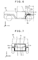
- FIG. 6 is a lateral view showing an electric vehicle 102 according to the second embodiment of the invention.
- FIG. 7 is a front view showing the electric vehicle 102.
- the diagrammatic representation of a motor is also omitted in FIGS. 6 and 7 .
- the electric vehicle 102 according to this second embodiment of the invention is an example in which the aforementioned attaching structure of the inverter is applied to a large-sized vehicle such as a pickup truck. In the case of a large-sized vehicle, the space of the front compartment 31 is high, and the space above front wheels is wide.
- the inverter 4 be arranged behind the center of the front compartment 31 in the longitudinal direction.
- a reference symbol L in FIG. 6 denotes the length of the front compartment 31 in the longitudinal direction.
- the inverter 4 is arranged in a posterior half range (a range indicated by L/2 in the drawing) of the front compartment 31.
- the inverter 4 be fixed to an upper portion of a fender apron 105a.
- the fender apron 105a constitutes part of a cabin outer plate 105, and is a location to which a front fender 108 is attached.
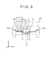
- FIG. 8 is a front view showing an electric vehicle 202 according to the third embodiment of the invention.
- the third embodiment of the invention is a modification example of the fixing structure of the inverter in the electric vehicle 2 according to the first embodiment of the invention.
- An inner side of the inverter 4 in the vehicle width direction, and an outer side of the inverter 4 in the vehicle width direction are fixed to a cabin outer plate 205. More specifically, the inner side of the inverter 4 and the outer side of the inverter 4 are fixed to the cabin outer plate 205 via brackets 207 by the bolts 14.
- the brackets are clasps for fixing an object.
- the brackets 207 are clasps for fixing the inverter 4 to the cabin outer plate 205.
- the cabin outer plate 205 is fixed to the frame member 3 by the bolt 13, inside the inverter 4 in the vehicle width direction (on a side close to the centerline CL). Then, the fixation strength between the cabin outer plate 205 and the frame member 3 is lower than the fixation strength of the outer side of the inverter 4 in the vehicle width direction. The fixation strength of the outer side of the inverter 4 in the vehicle width direction is adjusted such that an assumed collision impact can be tolerated. The fixation strength between the cabin outer plate 205 and the frame member 3 is adjusted such that the cabin outer plate 205 and the frame member 3 are disengaged from each other when the assumed collision impact is applied thereto.
- the same effect as in the electric vehicles according to the first and second embodiments of the invention is obtained from the structure of the third embodiment of the invention as well. That is, when the inverter 4 receives an impact, the cabin outer plate 205 and the side member 3 are released from being fixed to each other, so the inverter 4 is freed from the side member. As a result, the inverter 4 moves backward in accordance with the impact. The received impact is mitigated through the movement of the inverter 4.
- the fixation strength between the cabin outer plate 205 and the frame member 3 is lower than the fixation strength of the outer side of the inverter 4 in the vehicle width direction.
- the same advantage is also obtained by making the fixation strength of the inner side of the inverter 4 in the vehicle width direction lower than the fixation strength of the outer side of the inverter 4 in the vehicle width direction, instead of establishing such a relationship between the fixation strengths.
- the bracket 7 exemplified in the first embodiment of the invention may be used.
- Different fixation strengths can also be realized by changing the diameters of the bolts for fixing the inverter.
- a small-diameter bolt may be used to fix the outer side of the inverter in the vehicle width direction
- a large-diameter bolt may be utilized to fix the inner side of the inverter in the vehicle width direction, or to fix the cabin outer plate 205 and the frame member 3 to each other.
- the side members 3 extending in the longitudinal direction of the vehicle are equivalent to an example of the frame members.
Landscapes
- Engineering & Computer Science (AREA)
- Transportation (AREA)
- Mechanical Engineering (AREA)
- Power Engineering (AREA)
- Life Sciences & Earth Sciences (AREA)
- Sustainable Development (AREA)
- Sustainable Energy (AREA)
- Chemical & Material Sciences (AREA)
- Combustion & Propulsion (AREA)
- Arrangement Or Mounting Of Propulsion Units For Vehicles (AREA)
- Body Structure For Vehicles (AREA)
Abstract
Description
- The invention relates to an electric vehicle. In particular, the invention relates to a mounting structure of an inverter that converts a direct-current electric power of a battery into an alternating-current electric power and that supplies this alternating-current electric power to a motor in an electric vehicle. "The electric vehicle" in the present specification includes a fuel-cell vehicle and a hybrid vehicle equipped with an engine as well as a motor.
- There are two types of vehicle body structures, that is, a monocoque structure and a frame structure. The monocoque structure imparts a structural strength by a plate material. The frame structure imparts a structural strength by a frame as a combination of beams. A motor vehicle of the frame structure has two beams extending in a longitudinal direction, as main members that impart a structural strength. The beams are referred to as side members or side frames. The two side members are main members of the frame. The two side frames are coupled to each other by an auxiliary beam extending in a vehicle width direction.
- Main components of a drive train are arranged between the two side members in a front compartment, because a space between the two side members is suited to protect devices from an impact. A motor vehicle with an engine arranged between two side members is disclosed in, for example,
Japanese Patent Application Publication No. 2005-029057 JP 2005-029057 A Japanese Patent Application Publication No. 2004-175301 JP 2004-175301 A Japanese Patent Application Publication No. 2005-262894 JP 2005-262894 A - It is preferable that important devices be arranged between the two side members. In this case, however, the degree of freedom in arranging the devices is low. The present specification provides an art of effectively using a space of a front compartment of an electric vehicle. In the electric vehicle disclosed by the present specification, an inverter is arranged outside side members in a vehicle width direction, in a front compartment. Therefore, other devices can be arranged in a space between the two side members. It should be noted herein that "the side members" are a type of frame members of the vehicle as described above, and extend in a longitudinal direction of the vehicle. Besides, "the outside of the side members in the vehicle width direction" means a side that is further away from a center of the vehicle in the vehicle width direction than the side members. Besides, "the arrangement of the inverter outside the side members" does not necessarily mean that the entire inverter is located outside the side members. At least half of the inverter may be arranged outside the side members. Then, another device equivalent to half the volume of the inverter can be arranged between the two side members.
- The inverter may be preferably fixed in the following mode. An inner side of the inverter in the vehicle width direction is fixed to one of the frame members. An outer side of the inverter in the vehicle width direction is fixed to a cabin outer plate. "The cabin outer plate" is a shell-like metal plate that defines a cabin. Furthermore, it is appropriate that the inverter be arranged above or below the side members, and that a fixation strength of the inner side of the inverter be lower than a fixation strength of the outer side of the inverter. By making the fixation strengths different from each other, the fixation between the side member and the inverter is first released upon reception of an impact diagonally from in front, so the inverter is freed from the side member. On the other hand, the inverter is linked with the cabin outer plate. Therefore, upon receiving an impact, the inverter can move as the cabin outer plate is deformed. The impact received by the inverter is mitigated through the movement of the inverter.
- While the side members are made of high-rigidity iron, the cabin outer plate is made from a steel plate, so the material of the side members exhibits higher rigidity than the material of the cabin outer plate. Therefore, with a view to making the fixation strength between the inverter and the side member lower than the fixation strength between the inverter and the cabin outer plate, it is appropriate to adopt, for example, a bracket that is more likely to be disengaged (more likely to be ruptured) than in the case of direct fixation by a bolt.
- As described above, the degree of freedom in laying out the devices in the front compartment can be enhanced by arranging the inverter outside the two side members (outside in the vehicle width direction). Besides, the inner side of the inverter is fixed to one of the side members, and the outer side of the inverter is fixed to the cabin outer plate. Also, the fixation strength of the inner side is made lower than the fixation strength of the outer side. Thus, upon receiving an impact diagonally from in front of the vehicle, the inverter is freed from the side member, but remains coupled to the cabin outer plate. The inverter is allowed to move to a moderate degree, so the impact can be mitigated.
- In the aforementioned structure, the inner side of the inverter in the vehicle width direction is fixed to one of the frame members. The advantage of the structure can also be obtained from the following structure. That is, both the inner and outer sides of the inverter in the vehicle width direction are fixed to the cabin outer plate, and the cabin outer plate is fixed to one of the frame members inside the inverter in the vehicle width direction. Then, the fixation strength of the outer side of the inverter in the vehicle width direction is made higher than the fixation strength of the inner side of the inverter in the vehicle width direction or the fixation strength between the cabin outer plate and the frame member. In such a structure as well, upon receiving an impact diagonally from in front of the vehicle, the inverter is freed from the side member, but remains coupled to the cabin outer plate. The inverter is allowed to move to a moderate degree, so the impact can be mitigated.
- The details of the art disclosed by the present specification and further improvements thereof will be described subsequently with reference to embodiments of the invention.
-
- [
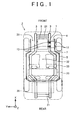
FIG. 1] FIG. 1 is a plan view of an electric vehicle according to the first embodiment of the invention. - [
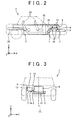
FIG. 2] FIG. 2 is a lateral view of the electric vehicle. - [
FIG. 3] FIG. 3 is a front view of the electric vehicle. - [
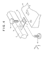
FIG. 4] FIG. 4 is an enlarged perspective view of a location where a side member and an inverter are fixed to each other. - [
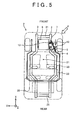
FIG. 5] FIG. 5 is a plan view showing an exemplary movement of the inverter upon reception of an impact diagonally from in front. - [
FIG. 6] FIG. 6 is a lateral view of an electric vehicle according to the second embodiment of the invention. - [
FIG. 7] FIG. 7 is a front view of the electric vehicle according to the second embodiment of the invention. - [
FIG. 8] FIG. 8 is a front view of an electric vehicle according to the third embodiment of the invention. - Some preferred features of the art described in the embodiments of the invention will be listed below as to an attaching structure of an inverter.
- (1) The inverter is located above a frame member.
- (2) The inverter is arranged on a fender apron.
- (3) The inverter is arranged behind a center of a front compartment in a longitudinal direction.
- (First Embodiment)
FIGS. 1 to 3 are plan, lateral and front views showing the electric vehicle according to the first embodiment of the invention, respectively. Incidentally, a relationship among frame members of the vehicle, a cabin outer plate, and the inverter will be described herein, so the diagrammatic representation and description of other components will be arbitrarily omitted. - A
front compartment 31 of anelectric vehicle 2 is mounted with atraction motor 6 and aninverter 4. Theinverter 4 converts a direct-current electric power of abattery 35, which is arranged in a luggage space in a rear part of the vehicle, into an alternating-current electric power, and supplies this alternating-current electric power to themotor 6. A large alternating current is supplied from theinverter 4 to themotor 6, so theinverter 4 is arranged close to themotor 6 with a view to reducing the transmission loss in electric power. Therefore, both themotor 6 and theinverter 4 are mounted in the front compartment. - The
electric vehicle 2 has a frame structure. Twoside members 3 are main components of a frame (frame members). The twoside members 3 mainly impart a structural strength to theelectric vehicle 2. The twoside members 3 extend parallel to a longitudinal direction of the vehicle, and are coupled to each other by a plurality ofcross members 21 that extend in a vehicle width direction. Themotor 6 is arranged between the twoside members 3. Themotor 6 is fixed to thecross members 21. Themotor 6 is arranged between the two high-strength side members 3. In the event of a collision of the vehicle, theside members 3 protect themotor 6. - The
inverter 4 is arranged outside theside members 3 in the vehicle width direction instead of being arranged between the twoside members 3. It should be noted, however, that theinverter 4 is fixed to one of theside members 3 via abracket 7 bybolts bracket 7 is a clasp for attaching theinverter 4 to theside member 3, and is made from a metal plate. - Besides, the
inverter 4 is also fixed to a cabinouter plate 5. The cabinouter plate 5 is a structure that defines a cabin (a boarding space 32), and is mainly made from a metal plate. Incidentally, areference numeral 33 in the drawings denotes a seat in which a passenger is seated. Theseat 33 is arranged in thecabin space 32. - As well shown in
FIGS. 1 and3 , theinverter 4 is fixed to theside member 3 via thebracket 7 inside in the vehicle width direction, and is fixed to the cabinouter plate 5 outside in the vehicle width direction. Incidentally, a straight line CL indicates a vehicle center in the vehicle width direction inFIG. 3 . Accordingly, the inside in the vehicle width direction means a side that is closer to a centerline CL than theside members 3, and the outside in the vehicle width direction means a side that is further away from the centerline CL than theside members 3. Besides, inFIG. 3 , the cabinouter plate 5 is depicted only in the vicinity of theinverter 4, and the other part of the cabinouter plate 5 is not shown. - The
bracket 7 is structured such that theinverter 4 is disengaged when a load of a predetermined magnitude is applied thereto. It should be noted herein that "the load of the predetermined magnitude" is a value lower than a fixation strength between the cabinouter plate 5 and theinverter 4. Besides, the fixation strength of thebracket 7 is adjusted such that theinverter 4 is disengaged from theside member 3 when an assumed collision impact is applied thereto. Conversely, the fixation strength between the cabinouter plate 5 and theinverter 4 is adjusted such that the assumed collision impact can be tolerated. -
FIG. 4 shows an exemplary structure of thebracket 7. It should be noted that the depiction is vertically inversed inFIG. 4 (see a coordinate system in the drawing). Thebracket 7 has a through-hole 7a and aslit 7b. Thebracket 7 is fixed to theside member 3 through the through-hole 7a by thebolt 13. On the other hand, thebracket 7 is fixed to theinverter 4 through theslit 7b by thebolt 14. A negative direction in an X-axis ofFIG. 4 is equivalent to a backward direction with respect to the vehicle. Theslit 7b opens backward with respect to the vehicle. Therefore, when the load of the predetermined magnitude is applied to theinverter 4 backward with respect to the vehicle (in a direction indicated by an arrow A inFIG. 4 ), theinverter 4 is disengaged from thebracket 7, namely, from theside member 3. - Advantages of the aforementioned structure of the
bracket 7 will be described.FIG. 5 is a plan view of the sameelectric vehicle 2 as inFIG. 1 . An arrow denoted by a reference symbol F represents an impact that theelectric vehicle 2 receives from right in front. Thick lines indicate deformation of the cabinouter plate 5 upon reception of an impact, and the movement of theinverter 4. Upon receiving an impact from right in front, a front-right portion of the cabinouter plate 5 bends leftward and backward. The outer side of theinverter 4 is fixed to the cabinouter plate 5, and the inner side of theinverter 4 is fixed to theside member 3. However, when the collision load applied backward exceeds the predetermined magnitude, theinverter 4 is disengaged from thebracket 7 to be freed from theside member 3. Therefore, theinverter 4 moves leftward and backward as the cabinouter plate 5 is deformed. Incidentally, as shown inFIGS. 2 and 3 , theinverter 4 is located above theside members 3. Accordingly, theinverter 4 can move leftward and backward without interfering with theside members 3. Upon receiving an impact, theinverter 4 is released from being fixed to theside member 3, and moves backward. The received impact is mitigated through the movement of theinverter 4. - In the aforementioned structure, the
inverter 4 is arranged outside the twoside members 3. Therefore, other important devices can be arranged in a space between theside members 3. Theelectric vehicle 2 according to the embodiment of the invention is advantageous in that the degree of freedom in laying out the devices in the front compartment is high. - (Second Embodiment) Next, the electric vehicle according to the second embodiment of the invention will be described.
FIG. 6 is a lateral view showing anelectric vehicle 102 according to the second embodiment of the invention.FIG. 7 is a front view showing theelectric vehicle 102. The diagrammatic representation of a motor is also omitted inFIGS. 6 and 7 . Theelectric vehicle 102 according to this second embodiment of the invention is an example in which the aforementioned attaching structure of the inverter is applied to a large-sized vehicle such as a pickup truck. In the case of a large-sized vehicle, the space of thefront compartment 31 is high, and the space above front wheels is wide. In such a case, it is appropriate that theinverter 4 be arranged behind the center of thefront compartment 31 in the longitudinal direction. A reference symbol L inFIG. 6 denotes the length of thefront compartment 31 in the longitudinal direction. Theinverter 4 is arranged in a posterior half range (a range indicated by L/2 in the drawing) of thefront compartment 31. By arranging theinverter 4 behind in the front compartment, the impact received by theinverter 4 in the event of a collision of the vehicle can be reduced. - Besides, when there is a space above the front wheels, it is appropriate that the
inverter 4 be fixed to an upper portion of afender apron 105a. Thefender apron 105a constitutes part of a cabinouter plate 105, and is a location to which afront fender 108 is attached. - (Third Embodiment) Next, the electric vehicle according to the third embodiment of the invention will be described.
FIG. 8 is a front view showing anelectric vehicle 202 according to the third embodiment of the invention. The third embodiment of the invention is a modification example of the fixing structure of the inverter in theelectric vehicle 2 according to the first embodiment of the invention. An inner side of theinverter 4 in the vehicle width direction, and an outer side of theinverter 4 in the vehicle width direction are fixed to a cabinouter plate 205. More specifically, the inner side of theinverter 4 and the outer side of theinverter 4 are fixed to the cabinouter plate 205 viabrackets 207 by thebolts 14. The brackets are clasps for fixing an object. In this case, thebrackets 207 are clasps for fixing theinverter 4 to the cabinouter plate 205. - The cabin
outer plate 205 is fixed to theframe member 3 by thebolt 13, inside theinverter 4 in the vehicle width direction (on a side close to the centerline CL). Then, the fixation strength between the cabinouter plate 205 and theframe member 3 is lower than the fixation strength of the outer side of theinverter 4 in the vehicle width direction. The fixation strength of the outer side of theinverter 4 in the vehicle width direction is adjusted such that an assumed collision impact can be tolerated. The fixation strength between the cabinouter plate 205 and theframe member 3 is adjusted such that the cabinouter plate 205 and theframe member 3 are disengaged from each other when the assumed collision impact is applied thereto. - The same effect as in the electric vehicles according to the first and second embodiments of the invention is obtained from the structure of the third embodiment of the invention as well. That is, when the
inverter 4 receives an impact, the cabinouter plate 205 and theside member 3 are released from being fixed to each other, so theinverter 4 is freed from the side member. As a result, theinverter 4 moves backward in accordance with the impact. The received impact is mitigated through the movement of theinverter 4. - Incidentally, in the third embodiment of the invention, the fixation strength between the cabin
outer plate 205 and theframe member 3 is lower than the fixation strength of the outer side of theinverter 4 in the vehicle width direction. The same advantage is also obtained by making the fixation strength of the inner side of theinverter 4 in the vehicle width direction lower than the fixation strength of the outer side of theinverter 4 in the vehicle width direction, instead of establishing such a relationship between the fixation strengths. - In order to realize different fixation strengths, the
bracket 7 exemplified in the first embodiment of the invention may be used. Different fixation strengths can also be realized by changing the diameters of the bolts for fixing the inverter. Concretely, a small-diameter bolt may be used to fix the outer side of the inverter in the vehicle width direction, and a large-diameter bolt may be utilized to fix the inner side of the inverter in the vehicle width direction, or to fix the cabinouter plate 205 and theframe member 3 to each other. - The points to remember about the art described in the embodiments of the invention will be mentioned. The
side members 3 extending in the longitudinal direction of the vehicle are equivalent to an example of the frame members. - The representative and nonrestrictive concrete examples of the invention have been described in detail with reference to the drawings. This detailed description is simply intended to inform those skilled in the art of the details for carrying out preferred examples of the invention, and is not intended to limit the scope of the invention. Besides, the disclosed additional features and inventions can be used separately from or in combination with other features and inventions, in order to provide a further improved electric vehicle.
- Besides, the features and combinations of processes disclosed in the aforementioned detailed description are not indispensable in the broadest sense in carrying out the invention, but are described for the sole purpose of explaining the representative concrete examples of the invention in particular. Furthermore, various features of the aforementioned representative concrete examples and various features of what is described in the independent and dependent claims are not required to be combined with one another as in the concrete examples described herein or according to the sequence of enumeration in providing additional and effective embodiments of the invention.
- All the features described in the present specification and/or the claims are intended to be disclosed individually and independently of one another as limitations on the contents disclosed at the time of the filing of the application and the specific matters described in the claims, separately from the configurations of the features described in the embodiments of the invention and/or the claims. Furthermore, all the numerical ranges and groups or aggregations are described as limitations on the contents disclosed at the time of the filing of the application and the specific matters described in the claims, with the intention of disclosing intermediate configurations thereof.
- Although the concrete examples of the invention have been described above in detail, these are nothing more than exemplifications, and should not limit the claims. The art described in the claims includes those obtained by modifying and altering the concrete examples exemplified above in various manners. The technical elements described in the present specification or the drawings are technically useful alone or in various combinations, and should not be limited to the combinations described in the claims at the time of the filing of the application. Besides, the art exemplified in the present specification or the drawings can achieve a plurality of objects at the same time, and is technically useful by achieving one of the objects itself.
-
- 2, 102, 202 ELECTRIC VEHICLE
- 3 SIDE MEMBER
- 4 INVERTER
- 5, 105, 205 CABIN OUTER PLATE
- 6 MOTOR
- 7,207 BRACKET
- 7a THROUGH-HOLE
- 7b SLIT
- 21 CROSS MEMBER
- 31 FRONT COMPARTMENT
- 32 CABIN SPACE
- 105a FENDER APRON
- 108 FRONT FENDER
- CL CENTERLINE
Claims (6)
- An electric vehicle characterized in that
an inverter that supplies an alternating-current electric power to a traction motor is arranged outside two frame members, which extend in a longitudinal direction of the vehicle, in a vehicle width direction, in a front compartment of the vehicle. - The electric vehicle according to claim 1, characterized in that
an inner side of the inverter in the vehicle width direction is fixed to one of the frame members,
an outer side of the inverter in the vehicle width direction is fixed to an outer plate of a cabin, and
a fixation strength of the inner side is lower than a fixation strength of the outer side. - The electric vehicle according to claim 1, characterized in that
an inner side of the inverter in the vehicle width direction and an outer side of the inverter in the vehicle width direction are fixed to an outer plate of a cabin,
the cabin outer plate is fixed to one of the frame members inside the inverter in the vehicle width direction, and
a fixation strength of the outer side of the inverter in the vehicle width direction is higher than a fixation strength of the inner side or a fixation strength between the cabin outer plate and the one of the frame members. - The electric vehicle according to any one of claims 1 to 3, characterized in that
the inverter is located above the frame members. - The electric vehicle according to any one of claims 1 to 4, characterized in that
the inverter is arranged on a fender apron. - The electric vehicle according to any one of claims 1 to 5, characterized in that
the inverter is arranged behind a center of the front compartment in the longitudinal direction.
Applications Claiming Priority (1)
| Application Number | Priority Date | Filing Date | Title |
|---|---|---|---|
| PCT/JP2013/054139 WO2014128855A1 (en) | 2013-02-20 | 2013-02-20 | Electric vehicle |
Publications (3)
| Publication Number | Publication Date |
|---|---|
| EP2960089A1 true EP2960089A1 (en) | 2015-12-30 |
| EP2960089A4 EP2960089A4 (en) | 2016-03-09 |
| EP2960089B1 EP2960089B1 (en) | 2017-10-04 |
Family
ID=51390688
Family Applications (1)
| Application Number | Title | Priority Date | Filing Date |
|---|---|---|---|
| EP13875908.9A Not-in-force EP2960089B1 (en) | 2013-02-20 | 2013-02-20 | Electric vehicle |
Country Status (8)
| Country | Link |
|---|---|
| US (1) | US9718362B2 (en) |
| EP (1) | EP2960089B1 (en) |
| JP (1) | JP5742967B2 (en) |
| KR (1) | KR101704955B1 (en) |
| CN (1) | CN104995051B (en) |
| BR (1) | BR112015018782B1 (en) |
| PH (1) | PH12015501829B1 (en) |
| WO (1) | WO2014128855A1 (en) |
Families Citing this family (20)
| Publication number | Priority date | Publication date | Assignee | Title |
|---|---|---|---|---|
| JP5827424B2 (en) * | 2012-12-21 | 2015-12-02 | 本田技研工業株式会社 | Motor mounting structure |
| BR112015018782B1 (en) * | 2013-02-20 | 2021-07-20 | Toyota Jidosha Kabushiki Kaisha | ELECTRIC VEHICLE |
| JP5920307B2 (en) * | 2013-10-04 | 2016-05-18 | トヨタ自動車株式会社 | Arrangement structure of inverter in fuel cell vehicle |
| JP6171946B2 (en) * | 2014-01-22 | 2017-08-02 | トヨタ自動車株式会社 | Car with battery pack |
| JP6063406B2 (en) * | 2014-03-06 | 2017-01-18 | 本田技研工業株式会社 | Fuel cell stack mounting structure |
| FR3025572B1 (en) * | 2014-09-05 | 2017-02-24 | Renault Sa | VEHICLE WITH AN INCOMPRESSIBLE ELEMENT FIXED ON A COMPRESSIBLE ELEMENT IN CASE OF COLLISION |
| US10112563B2 (en) | 2015-06-30 | 2018-10-30 | Faraday & Future Inc. | Tapered crush can |
| US10131381B2 (en) * | 2015-06-30 | 2018-11-20 | Faraday & Future Inc. | Joint for an underbody of a motor vehicle |
| US10300948B2 (en) | 2015-10-30 | 2019-05-28 | Faraday&Future Inc. | Webbing devices for an underbody of a motor vehicle |
| CN105751882A (en) * | 2016-04-14 | 2016-07-13 | 北京新能源汽车股份有限公司 | Electric automobile |
| KR102120664B1 (en) * | 2016-05-25 | 2020-06-09 | 닛산 지도우샤 가부시키가이샤 | Mounting structure of power converter |
| JP6439177B2 (en) * | 2016-09-27 | 2018-12-19 | 本田技研工業株式会社 | Lower body structure |
| JP6658500B2 (en) * | 2016-12-26 | 2020-03-04 | トヨタ自動車株式会社 | Fuel cell mounting structure |
| US9963028B1 (en) * | 2017-02-21 | 2018-05-08 | Ford Global Technologies, Llc | Battery support structure for electrified vehicle |
| JP6848626B2 (en) * | 2017-04-05 | 2021-03-24 | トヨタ自動車株式会社 | Vehicle front structure |
| JP7151112B2 (en) * | 2018-03-22 | 2022-10-12 | マツダ株式会社 | Electric vehicle front unit mounting structure |
| US11007899B2 (en) * | 2018-10-23 | 2021-05-18 | Chongqing Jinkang New Energy Vehicle Co., Ltd | Mounting structures for battery packs in electric vehicles |
| JP7360834B2 (en) * | 2019-07-12 | 2023-10-13 | メルセデス・ベンツ グループ アクチェンゲゼルシャフト | electric truck |
| CN115366641A (en) * | 2022-08-02 | 2022-11-22 | 苏州江南航天机电工业有限公司 | Quick assembly disassembly anti loosening structure of generator |
| FR3158913B1 (en) * | 2024-02-01 | 2026-01-30 | Ampere Sas | Mounting system for a high-power electronic component of an electric or hybrid vehicle, vehicle chassis including the mounting system and electric or hybrid vehicle including the chassis |
Family Cites Families (31)
| Publication number | Priority date | Publication date | Assignee | Title |
|---|---|---|---|---|
| DE69105016T2 (en) * | 1990-03-30 | 1995-03-23 | Mazda Motor | Front body structure of a motor vehicle. |
| US5267630A (en) * | 1991-04-23 | 1993-12-07 | Mazda Motor Corporation | Front body structure of automotive vehicle |
| JPH07101353A (en) * | 1993-10-01 | 1995-04-18 | Toyota Motor Corp | Vehicle-mounted device mounting structure |
| DE4344581C1 (en) * | 1993-12-24 | 1994-12-01 | Daimler Benz Ag | Motor vehicle and method of manufacturing a motor vehicle |
| JPH08310252A (en) | 1995-05-17 | 1996-11-26 | Nissan Motor Co Ltd | Mounting structure and mounting method for parts in motor room of electric vehicle |
| JP4245701B2 (en) * | 1998-10-05 | 2009-04-02 | 富士重工業株式会社 | Front body structure of automobile |
| JP4072882B2 (en) * | 1999-09-30 | 2008-04-09 | 富士重工業株式会社 | Mounting structure of auxiliary parts for in-vehicle use |
| JP4601837B2 (en) * | 2001-02-06 | 2010-12-22 | 富士重工業株式会社 | Battery bracket structure |
| JP4118130B2 (en) | 2002-11-28 | 2008-07-16 | トヨタ自動車株式会社 | Electric car |
| US7185725B2 (en) | 2003-07-07 | 2007-03-06 | Mazda Motor Corporation | Layout structure of driving device for vehicle |
| JP4363106B2 (en) | 2003-07-08 | 2009-11-11 | マツダ株式会社 | Auxiliary equipment arrangement structure in vehicle engine room |
| SE525475C2 (en) * | 2003-07-08 | 2005-03-01 | Volvo Lastvagnar Ab | System for connecting bodywork to a truck and device included in the system |
| JP4515757B2 (en) * | 2003-12-25 | 2010-08-04 | 富士重工業株式会社 | Battery retention structure |
| JP2005262894A (en) | 2004-03-16 | 2005-09-29 | Toyota Motor Corp | Vehicle with high voltage line |
| JP4371036B2 (en) * | 2004-10-20 | 2009-11-25 | 日産自動車株式会社 | Hybrid vehicle inverter buffer structure |
| JP4701754B2 (en) * | 2005-03-09 | 2011-06-15 | トヨタ自動車株式会社 | Electrical equipment mounting structure |
| JP2007161111A (en) * | 2005-12-14 | 2007-06-28 | Toyota Motor Corp | Vehicle drive device |
| JP5141026B2 (en) * | 2006-02-27 | 2013-02-13 | トヨタ自動車株式会社 | In-vehicle structure of power storage pack |
| JP4935112B2 (en) * | 2006-02-28 | 2012-05-23 | トヨタ自動車株式会社 | In-vehicle structure of power storage pack |
| KR100857345B1 (en) * | 2006-12-14 | 2008-09-05 | 현대자동차주식회사 | Part layout of fuel cell vehicle |
| EP2119585B1 (en) * | 2007-03-06 | 2012-08-01 | Toyota Jidosha Kabushiki Kaisha | Vehicle |
| JP5060220B2 (en) * | 2007-09-06 | 2012-10-31 | 三菱自動車工業株式会社 | Electric car |
| JP5187208B2 (en) * | 2009-01-30 | 2013-04-24 | トヨタ自動車株式会社 | Power control unit support structure |
| US8459399B2 (en) * | 2009-05-28 | 2013-06-11 | Toyota Jidosha Kabushiki Kaisha | Fuel cell system and vehicle |
| BR112012001982A2 (en) * | 2009-07-28 | 2016-03-29 | Honda Motor Co Ltd | structure for placing electronic component inside the vehicle for electronic component for electric motor for automobiles |
| JP4858607B2 (en) * | 2009-12-14 | 2012-01-18 | トヨタ自動車株式会社 | Power supply |
| US8336657B2 (en) * | 2010-02-12 | 2012-12-25 | Ford Global Technologies, Llc | Support structure for inverter system controller module |
| JP5156057B2 (en) * | 2010-06-25 | 2013-03-06 | 富士重工業株式会社 | Mounting structure for vehicle battery box |
| JP5110130B2 (en) * | 2010-07-27 | 2012-12-26 | 株式会社デンソー | In-vehicle electronic control unit housing |
| WO2014057514A1 (en) * | 2012-10-10 | 2014-04-17 | 川崎重工業株式会社 | Electric vehicle |
| BR112015018782B1 (en) * | 2013-02-20 | 2021-07-20 | Toyota Jidosha Kabushiki Kaisha | ELECTRIC VEHICLE |
-
2013
- 2013-02-20 BR BR112015018782-0A patent/BR112015018782B1/en not_active IP Right Cessation
- 2013-02-20 US US14/767,023 patent/US9718362B2/en active Active
- 2013-02-20 KR KR1020157022306A patent/KR101704955B1/en not_active Expired - Fee Related
- 2013-02-20 EP EP13875908.9A patent/EP2960089B1/en not_active Not-in-force
- 2013-02-20 JP JP2013553709A patent/JP5742967B2/en active Active
- 2013-02-20 WO PCT/JP2013/054139 patent/WO2014128855A1/en not_active Ceased
- 2013-02-20 CN CN201380073265.8A patent/CN104995051B/en not_active Expired - Fee Related
-
2015
- 2015-08-19 PH PH12015501829A patent/PH12015501829B1/en unknown
Also Published As
| Publication number | Publication date |
|---|---|
| CN104995051A (en) | 2015-10-21 |
| EP2960089A4 (en) | 2016-03-09 |
| KR101704955B1 (en) | 2017-02-08 |
| WO2014128855A1 (en) | 2014-08-28 |
| JPWO2014128855A1 (en) | 2017-02-02 |
| EP2960089B1 (en) | 2017-10-04 |
| US9718362B2 (en) | 2017-08-01 |
| BR112015018782B1 (en) | 2021-07-20 |
| JP5742967B2 (en) | 2015-07-01 |
| KR20150110648A (en) | 2015-10-02 |
| BR112015018782A2 (en) | 2017-07-18 |
| PH12015501829A1 (en) | 2015-11-09 |
| US20150375622A1 (en) | 2015-12-31 |
| CN104995051B (en) | 2017-09-05 |
| PH12015501829B1 (en) | 2015-11-09 |
Similar Documents
| Publication | Publication Date | Title |
|---|---|---|
| US9718362B2 (en) | Electric vehicle | |
| EP3069962B1 (en) | Automobile vehicle body structure | |
| US10232883B2 (en) | Vehicle equipped with traveling motor | |
| US10676135B2 (en) | Front vehicle body reinforcing structure | |
| US20120118653A1 (en) | In-vehicle electronic component disposing construction for electronic component for electric motor for driving vehicle | |
| CN104627096B (en) | High-voltage wire wiring structure in vehicle | |
| US20210221239A1 (en) | Electric vehicle structure | |
| EP3437964B1 (en) | Vehicle front portion structure | |
| CN114590326A (en) | Underbody for battery electric vehicle | |
| US11701958B2 (en) | Electric powered vehicle | |
| CN105416405A (en) | Automobile instrument board beam assembly and installing method thereof | |
| JP2015137001A (en) | Electric vehicle | |
| KR20220111193A (en) | Motor vehicle body having a battery compartment, motor vehicle | |
| US11912344B2 (en) | Vehicle lower part structure | |
| US10703414B2 (en) | Vehicle front portion structure | |
| CN110316137B (en) | Mounting structure of knee airbag device for vehicle | |
| JP2016107907A (en) | Electric power conversion system | |
| EP4063157B1 (en) | Electric vehicle and its lower structure | |
| CN116507517B (en) | Electric truck | |
| JP6693093B2 (en) | vehicle | |
| US20240149707A1 (en) | Vehicle | |
| JP2016159783A (en) | Electric vehicle | |
| CN202071785U (en) | Hybrid car provided with at least one high-tension line |
Legal Events
| Date | Code | Title | Description |
|---|---|---|---|
| PUAI | Public reference made under article 153(3) epc to a published international application that has entered the european phase |
Free format text: ORIGINAL CODE: 0009012 |
|
| 17P | Request for examination filed |
Effective date: 20150817 |
|
| AK | Designated contracting states |
Kind code of ref document: A1 Designated state(s): AL AT BE BG CH CY CZ DE DK EE ES FI FR GB GR HR HU IE IS IT LI LT LU LV MC MK MT NL NO PL PT RO RS SE SI SK SM TR |
|
| AX | Request for extension of the european patent |
Extension state: BA ME |
|
| A4 | Supplementary search report drawn up and despatched |
Effective date: 20160204 |
|
| RIC1 | Information provided on ipc code assigned before grant |
Ipc: B60K 1/00 20060101AFI20160129BHEP Ipc: B60L 3/00 20060101ALI20160129BHEP Ipc: B60L 15/00 20060101ALI20160129BHEP |
|
| DAX | Request for extension of the european patent (deleted) | ||
| GRAP | Despatch of communication of intention to grant a patent |
Free format text: ORIGINAL CODE: EPIDOSNIGR1 |
|
| INTG | Intention to grant announced |
Effective date: 20170428 |
|
| GRAA | (expected) grant |
Free format text: ORIGINAL CODE: 0009210 |
|
| GRAS | Grant fee paid |
Free format text: ORIGINAL CODE: EPIDOSNIGR3 |
|
| AK | Designated contracting states |
Kind code of ref document: B1 Designated state(s): AL AT BE BG CH CY CZ DE DK EE ES FI FR GB GR HR HU IE IS IT LI LT LU LV MC MK MT NL NO PL PT RO RS SE SI SK SM TR |
|
| REG | Reference to a national code |
Ref country code: GB Ref legal event code: FG4D |
|
| REG | Reference to a national code |
Ref country code: CH Ref legal event code: EP |
|
| REG | Reference to a national code |
Ref country code: AT Ref legal event code: REF Ref document number: 933654 Country of ref document: AT Kind code of ref document: T Effective date: 20171015 |
|
| REG | Reference to a national code |
Ref country code: IE Ref legal event code: FG4D |
|
| REG | Reference to a national code |
Ref country code: DE Ref legal event code: R096 Ref document number: 602013027685 Country of ref document: DE |
|
| REG | Reference to a national code |
Ref country code: DE Ref legal event code: R084 Ref document number: 602013027685 Country of ref document: DE |
|
| REG | Reference to a national code |
Ref country code: GB Ref legal event code: 746 Effective date: 20171124 |
|
| REG | Reference to a national code |
Ref country code: FR Ref legal event code: PLFP Year of fee payment: 6 |
|
| REG | Reference to a national code |
Ref country code: NL Ref legal event code: MP Effective date: 20171004 |
|
| REG | Reference to a national code |
Ref country code: LT Ref legal event code: MG4D |
|
| REG | Reference to a national code |
Ref country code: AT Ref legal event code: MK05 Ref document number: 933654 Country of ref document: AT Kind code of ref document: T Effective date: 20171004 |
|
| PG25 | Lapsed in a contracting state [announced via postgrant information from national office to epo] |
Ref country code: NL Free format text: LAPSE BECAUSE OF FAILURE TO SUBMIT A TRANSLATION OF THE DESCRIPTION OR TO PAY THE FEE WITHIN THE PRESCRIBED TIME-LIMIT Effective date: 20171004 |
|
| PG25 | Lapsed in a contracting state [announced via postgrant information from national office to epo] |
Ref country code: FI Free format text: LAPSE BECAUSE OF FAILURE TO SUBMIT A TRANSLATION OF THE DESCRIPTION OR TO PAY THE FEE WITHIN THE PRESCRIBED TIME-LIMIT Effective date: 20171004 Ref country code: NO Free format text: LAPSE BECAUSE OF FAILURE TO SUBMIT A TRANSLATION OF THE DESCRIPTION OR TO PAY THE FEE WITHIN THE PRESCRIBED TIME-LIMIT Effective date: 20180104 Ref country code: SE Free format text: LAPSE BECAUSE OF FAILURE TO SUBMIT A TRANSLATION OF THE DESCRIPTION OR TO PAY THE FEE WITHIN THE PRESCRIBED TIME-LIMIT Effective date: 20171004 Ref country code: LT Free format text: LAPSE BECAUSE OF FAILURE TO SUBMIT A TRANSLATION OF THE DESCRIPTION OR TO PAY THE FEE WITHIN THE PRESCRIBED TIME-LIMIT Effective date: 20171004 Ref country code: ES Free format text: LAPSE BECAUSE OF FAILURE TO SUBMIT A TRANSLATION OF THE DESCRIPTION OR TO PAY THE FEE WITHIN THE PRESCRIBED TIME-LIMIT Effective date: 20171004 |
|
| PG25 | Lapsed in a contracting state [announced via postgrant information from national office to epo] |
Ref country code: RS Free format text: LAPSE BECAUSE OF FAILURE TO SUBMIT A TRANSLATION OF THE DESCRIPTION OR TO PAY THE FEE WITHIN THE PRESCRIBED TIME-LIMIT Effective date: 20171004 Ref country code: GR Free format text: LAPSE BECAUSE OF FAILURE TO SUBMIT A TRANSLATION OF THE DESCRIPTION OR TO PAY THE FEE WITHIN THE PRESCRIBED TIME-LIMIT Effective date: 20180105 Ref country code: LV Free format text: LAPSE BECAUSE OF FAILURE TO SUBMIT A TRANSLATION OF THE DESCRIPTION OR TO PAY THE FEE WITHIN THE PRESCRIBED TIME-LIMIT Effective date: 20171004 Ref country code: IS Free format text: LAPSE BECAUSE OF FAILURE TO SUBMIT A TRANSLATION OF THE DESCRIPTION OR TO PAY THE FEE WITHIN THE PRESCRIBED TIME-LIMIT Effective date: 20180204 Ref country code: BG Free format text: LAPSE BECAUSE OF FAILURE TO SUBMIT A TRANSLATION OF THE DESCRIPTION OR TO PAY THE FEE WITHIN THE PRESCRIBED TIME-LIMIT Effective date: 20180104 Ref country code: HR Free format text: LAPSE BECAUSE OF FAILURE TO SUBMIT A TRANSLATION OF THE DESCRIPTION OR TO PAY THE FEE WITHIN THE PRESCRIBED TIME-LIMIT Effective date: 20171004 Ref country code: AT Free format text: LAPSE BECAUSE OF FAILURE TO SUBMIT A TRANSLATION OF THE DESCRIPTION OR TO PAY THE FEE WITHIN THE PRESCRIBED TIME-LIMIT Effective date: 20171004 |
|
| REG | Reference to a national code |
Ref country code: DE Ref legal event code: R097 Ref document number: 602013027685 Country of ref document: DE |
|
| PG25 | Lapsed in a contracting state [announced via postgrant information from national office to epo] |
Ref country code: CZ Free format text: LAPSE BECAUSE OF FAILURE TO SUBMIT A TRANSLATION OF THE DESCRIPTION OR TO PAY THE FEE WITHIN THE PRESCRIBED TIME-LIMIT Effective date: 20171004 Ref country code: SK Free format text: LAPSE BECAUSE OF FAILURE TO SUBMIT A TRANSLATION OF THE DESCRIPTION OR TO PAY THE FEE WITHIN THE PRESCRIBED TIME-LIMIT Effective date: 20171004 Ref country code: EE Free format text: LAPSE BECAUSE OF FAILURE TO SUBMIT A TRANSLATION OF THE DESCRIPTION OR TO PAY THE FEE WITHIN THE PRESCRIBED TIME-LIMIT Effective date: 20171004 Ref country code: DK Free format text: LAPSE BECAUSE OF FAILURE TO SUBMIT A TRANSLATION OF THE DESCRIPTION OR TO PAY THE FEE WITHIN THE PRESCRIBED TIME-LIMIT Effective date: 20171004 |
|
| PLBE | No opposition filed within time limit |
Free format text: ORIGINAL CODE: 0009261 |
|
| STAA | Information on the status of an ep patent application or granted ep patent |
Free format text: STATUS: NO OPPOSITION FILED WITHIN TIME LIMIT |
|
| PG25 | Lapsed in a contracting state [announced via postgrant information from national office to epo] |
Ref country code: RO Free format text: LAPSE BECAUSE OF FAILURE TO SUBMIT A TRANSLATION OF THE DESCRIPTION OR TO PAY THE FEE WITHIN THE PRESCRIBED TIME-LIMIT Effective date: 20171004 Ref country code: PL Free format text: LAPSE BECAUSE OF FAILURE TO SUBMIT A TRANSLATION OF THE DESCRIPTION OR TO PAY THE FEE WITHIN THE PRESCRIBED TIME-LIMIT Effective date: 20171004 Ref country code: SM Free format text: LAPSE BECAUSE OF FAILURE TO SUBMIT A TRANSLATION OF THE DESCRIPTION OR TO PAY THE FEE WITHIN THE PRESCRIBED TIME-LIMIT Effective date: 20171004 Ref country code: IT Free format text: LAPSE BECAUSE OF FAILURE TO SUBMIT A TRANSLATION OF THE DESCRIPTION OR TO PAY THE FEE WITHIN THE PRESCRIBED TIME-LIMIT Effective date: 20171004 |
|
| 26N | No opposition filed |
Effective date: 20180705 |
|
| REG | Reference to a national code |
Ref country code: CH Ref legal event code: PL |
|
| PG25 | Lapsed in a contracting state [announced via postgrant information from national office to epo] |
Ref country code: MC Free format text: LAPSE BECAUSE OF FAILURE TO SUBMIT A TRANSLATION OF THE DESCRIPTION OR TO PAY THE FEE WITHIN THE PRESCRIBED TIME-LIMIT Effective date: 20171004 |
|
| REG | Reference to a national code |
Ref country code: IE Ref legal event code: MM4A |
|
| REG | Reference to a national code |
Ref country code: BE Ref legal event code: MM Effective date: 20180228 |
|
| PG25 | Lapsed in a contracting state [announced via postgrant information from national office to epo] |
Ref country code: SI Free format text: LAPSE BECAUSE OF FAILURE TO SUBMIT A TRANSLATION OF THE DESCRIPTION OR TO PAY THE FEE WITHIN THE PRESCRIBED TIME-LIMIT Effective date: 20171004 Ref country code: CH Free format text: LAPSE BECAUSE OF NON-PAYMENT OF DUE FEES Effective date: 20180228 Ref country code: LI Free format text: LAPSE BECAUSE OF NON-PAYMENT OF DUE FEES Effective date: 20180228 Ref country code: LU Free format text: LAPSE BECAUSE OF NON-PAYMENT OF DUE FEES Effective date: 20180220 |
|
| PG25 | Lapsed in a contracting state [announced via postgrant information from national office to epo] |
Ref country code: IE Free format text: LAPSE BECAUSE OF NON-PAYMENT OF DUE FEES Effective date: 20180220 |
|
| PG25 | Lapsed in a contracting state [announced via postgrant information from national office to epo] |
Ref country code: BE Free format text: LAPSE BECAUSE OF NON-PAYMENT OF DUE FEES Effective date: 20180228 |
|
| PG25 | Lapsed in a contracting state [announced via postgrant information from national office to epo] |
Ref country code: MT Free format text: LAPSE BECAUSE OF NON-PAYMENT OF DUE FEES Effective date: 20180220 |
|
| PG25 | Lapsed in a contracting state [announced via postgrant information from national office to epo] |
Ref country code: TR Free format text: LAPSE BECAUSE OF FAILURE TO SUBMIT A TRANSLATION OF THE DESCRIPTION OR TO PAY THE FEE WITHIN THE PRESCRIBED TIME-LIMIT Effective date: 20171004 |
|
| PG25 | Lapsed in a contracting state [announced via postgrant information from national office to epo] |
Ref country code: PT Free format text: LAPSE BECAUSE OF FAILURE TO SUBMIT A TRANSLATION OF THE DESCRIPTION OR TO PAY THE FEE WITHIN THE PRESCRIBED TIME-LIMIT Effective date: 20171004 |
|
| PG25 | Lapsed in a contracting state [announced via postgrant information from national office to epo] |
Ref country code: MK Free format text: LAPSE BECAUSE OF NON-PAYMENT OF DUE FEES Effective date: 20171004 Ref country code: CY Free format text: LAPSE BECAUSE OF FAILURE TO SUBMIT A TRANSLATION OF THE DESCRIPTION OR TO PAY THE FEE WITHIN THE PRESCRIBED TIME-LIMIT Effective date: 20171004 Ref country code: HU Free format text: LAPSE BECAUSE OF FAILURE TO SUBMIT A TRANSLATION OF THE DESCRIPTION OR TO PAY THE FEE WITHIN THE PRESCRIBED TIME-LIMIT; INVALID AB INITIO Effective date: 20130220 |
|
| PG25 | Lapsed in a contracting state [announced via postgrant information from national office to epo] |
Ref country code: AL Free format text: LAPSE BECAUSE OF FAILURE TO SUBMIT A TRANSLATION OF THE DESCRIPTION OR TO PAY THE FEE WITHIN THE PRESCRIBED TIME-LIMIT Effective date: 20171004 |
|
| PGFP | Annual fee paid to national office [announced via postgrant information from national office to epo] |
Ref country code: GB Payment date: 20211231 Year of fee payment: 10 |
|
| PGFP | Annual fee paid to national office [announced via postgrant information from national office to epo] |
Ref country code: DE Payment date: 20211230 Year of fee payment: 10 |
|
| PGFP | Annual fee paid to national office [announced via postgrant information from national office to epo] |
Ref country code: FR Payment date: 20220118 Year of fee payment: 10 |
|
| P01 | Opt-out of the competence of the unified patent court (upc) registered |
Effective date: 20230427 |
|
| REG | Reference to a national code |
Ref country code: DE Ref legal event code: R119 Ref document number: 602013027685 Country of ref document: DE |
|
| GBPC | Gb: european patent ceased through non-payment of renewal fee |
Effective date: 20230220 |
|
| PG25 | Lapsed in a contracting state [announced via postgrant information from national office to epo] |
Ref country code: GB Free format text: LAPSE BECAUSE OF NON-PAYMENT OF DUE FEES Effective date: 20230220 |
|
| PG25 | Lapsed in a contracting state [announced via postgrant information from national office to epo] |
Ref country code: GB Free format text: LAPSE BECAUSE OF NON-PAYMENT OF DUE FEES Effective date: 20230220 Ref country code: FR Free format text: LAPSE BECAUSE OF NON-PAYMENT OF DUE FEES Effective date: 20230228 Ref country code: DE Free format text: LAPSE BECAUSE OF NON-PAYMENT OF DUE FEES Effective date: 20230901 |