EP2959936A1 - Implantierbare kapsel mit fixierung durch verschraubung, insbesondere autonome herzstimulationskapsel - Google Patents
Implantierbare kapsel mit fixierung durch verschraubung, insbesondere autonome herzstimulationskapsel Download PDFInfo
- Publication number
- EP2959936A1 EP2959936A1 EP15167098.1A EP15167098A EP2959936A1 EP 2959936 A1 EP2959936 A1 EP 2959936A1 EP 15167098 A EP15167098 A EP 15167098A EP 2959936 A1 EP2959936 A1 EP 2959936A1
- Authority
- EP
- European Patent Office
- Prior art keywords
- capsule
- screw
- support
- capsule according
- annular
- Prior art date
- Legal status (The legal status is an assumption and is not a legal conclusion. Google has not performed a legal analysis and makes no representation as to the accuracy of the status listed.)
- Granted
Links
- 239000002775 capsule Substances 0.000 title claims abstract description 74
- 230000000638 stimulation Effects 0.000 title claims abstract description 17
- 230000000747 cardiac effect Effects 0.000 title claims abstract description 15
- 238000004873 anchoring Methods 0.000 claims abstract description 13
- 210000000056 organ Anatomy 0.000 claims abstract description 3
- 239000000463 material Substances 0.000 claims description 17
- 229920000747 poly(lactic acid) Polymers 0.000 claims description 8
- 229920000954 Polyglycolide Polymers 0.000 claims description 6
- 238000009792 diffusion process Methods 0.000 claims description 5
- 229920001222 biopolymer Polymers 0.000 claims description 3
- 239000003814 drug Substances 0.000 claims 1
- 229940079593 drug Drugs 0.000 claims 1
- 229920001606 poly(lactic acid-co-glycolic acid) Polymers 0.000 claims 1
- 210000003038 endothelium Anatomy 0.000 description 12
- 210000001519 tissue Anatomy 0.000 description 11
- 239000000523 sample Substances 0.000 description 9
- 238000003466 welding Methods 0.000 description 9
- 238000000034 method Methods 0.000 description 8
- 210000002216 heart Anatomy 0.000 description 6
- 230000000694 effects Effects 0.000 description 5
- 239000007943 implant Substances 0.000 description 4
- 150000003431 steroids Chemical class 0.000 description 4
- 208000027418 Wounds and injury Diseases 0.000 description 3
- 238000004026 adhesive bonding Methods 0.000 description 3
- 238000003754 machining Methods 0.000 description 3
- 210000003205 muscle Anatomy 0.000 description 3
- 239000010935 stainless steel Substances 0.000 description 3
- 229910001220 stainless steel Inorganic materials 0.000 description 3
- 208000031968 Cadaver Diseases 0.000 description 2
- 229910001069 Ti alloy Inorganic materials 0.000 description 2
- RTAQQCXQSZGOHL-UHFFFAOYSA-N Titanium Chemical compound [Ti] RTAQQCXQSZGOHL-UHFFFAOYSA-N 0.000 description 2
- 230000008901 benefit Effects 0.000 description 2
- 210000005242 cardiac chamber Anatomy 0.000 description 2
- 230000006378 damage Effects 0.000 description 2
- 238000001514 detection method Methods 0.000 description 2
- 238000010304 firing Methods 0.000 description 2
- 238000002513 implantation Methods 0.000 description 2
- 230000014759 maintenance of location Effects 0.000 description 2
- 238000012544 monitoring process Methods 0.000 description 2
- 210000004165 myocardium Anatomy 0.000 description 2
- 230000035515 penetration Effects 0.000 description 2
- BASFCYQUMIYNBI-UHFFFAOYSA-N platinum Chemical compound [Pt] BASFCYQUMIYNBI-UHFFFAOYSA-N 0.000 description 2
- 239000010936 titanium Substances 0.000 description 2
- 229910052719 titanium Inorganic materials 0.000 description 2
- 238000013519 translation Methods 0.000 description 2
- 230000000472 traumatic effect Effects 0.000 description 2
- 206010016654 Fibrosis Diseases 0.000 description 1
- 206010061218 Inflammation Diseases 0.000 description 1
- 235000002790 Monstera deliciosa Nutrition 0.000 description 1
- 240000000987 Monstera deliciosa Species 0.000 description 1
- 230000009471 action Effects 0.000 description 1
- 230000006978 adaptation Effects 0.000 description 1
- 230000032683 aging Effects 0.000 description 1
- 230000004323 axial length Effects 0.000 description 1
- 239000011324 bead Substances 0.000 description 1
- 239000008280 blood Substances 0.000 description 1
- 210000004369 blood Anatomy 0.000 description 1
- 210000004903 cardiac system Anatomy 0.000 description 1
- 230000006835 compression Effects 0.000 description 1
- 238000007906 compression Methods 0.000 description 1
- 239000004020 conductor Substances 0.000 description 1
- 238000007796 conventional method Methods 0.000 description 1
- 238000002788 crimping Methods 0.000 description 1
- 230000000593 degrading effect Effects 0.000 description 1
- UREBDLICKHMUKA-CXSFZGCWSA-N dexamethasone Chemical compound C1CC2=CC(=O)C=C[C@]2(C)[C@]2(F)[C@@H]1[C@@H]1C[C@@H](C)[C@@](C(=O)CO)(O)[C@@]1(C)C[C@@H]2O UREBDLICKHMUKA-CXSFZGCWSA-N 0.000 description 1
- 229960003957 dexamethasone Drugs 0.000 description 1
- 201000010099 disease Diseases 0.000 description 1
- 208000037265 diseases, disorders, signs and symptoms Diseases 0.000 description 1
- 230000004761 fibrosis Effects 0.000 description 1
- 230000004927 fusion Effects 0.000 description 1
- 210000002837 heart atrium Anatomy 0.000 description 1
- 210000005003 heart tissue Anatomy 0.000 description 1
- 230000004054 inflammatory process Effects 0.000 description 1
- 208000014674 injury Diseases 0.000 description 1
- 238000009434 installation Methods 0.000 description 1
- 229910052741 iridium Inorganic materials 0.000 description 1
- GKOZUEZYRPOHIO-UHFFFAOYSA-N iridium atom Chemical compound [Ir] GKOZUEZYRPOHIO-UHFFFAOYSA-N 0.000 description 1
- 238000005304 joining Methods 0.000 description 1
- 238000012423 maintenance Methods 0.000 description 1
- 229910001092 metal group alloy Inorganic materials 0.000 description 1
- 230000004048 modification Effects 0.000 description 1
- 238000012986 modification Methods 0.000 description 1
- 238000012806 monitoring device Methods 0.000 description 1
- 239000008188 pellet Substances 0.000 description 1
- 230000000149 penetrating effect Effects 0.000 description 1
- 229910052697 platinum Inorganic materials 0.000 description 1
- 229920002643 polyglutamic acid Polymers 0.000 description 1
- 230000002265 prevention Effects 0.000 description 1
- 230000008569 process Effects 0.000 description 1
- 230000000750 progressive effect Effects 0.000 description 1
- 238000011084 recovery Methods 0.000 description 1
- 230000033764 rhythmic process Effects 0.000 description 1
- 238000007493 shaping process Methods 0.000 description 1
- 230000004936 stimulating effect Effects 0.000 description 1
- 230000035882 stress Effects 0.000 description 1
- 230000000451 tissue damage Effects 0.000 description 1
- 231100000827 tissue damage Toxicity 0.000 description 1
- 230000000007 visual effect Effects 0.000 description 1
- 230000002747 voluntary effect Effects 0.000 description 1
- 238000004804 winding Methods 0.000 description 1
Images


Classifications
-
- A—HUMAN NECESSITIES
- A61—MEDICAL OR VETERINARY SCIENCE; HYGIENE
- A61N—ELECTROTHERAPY; MAGNETOTHERAPY; RADIATION THERAPY; ULTRASOUND THERAPY
- A61N1/00—Electrotherapy; Circuits therefor
- A61N1/02—Details
- A61N1/04—Electrodes
- A61N1/05—Electrodes for implantation or insertion into the body, e.g. heart electrode
- A61N1/056—Transvascular endocardial electrode systems
- A61N1/057—Anchoring means; Means for fixing the head inside the heart
- A61N1/0573—Anchoring means; Means for fixing the head inside the heart chacterised by means penetrating the heart tissue, e.g. helix needle or hook
- A61N1/0575—Anchoring means; Means for fixing the head inside the heart chacterised by means penetrating the heart tissue, e.g. helix needle or hook with drug delivery
-
- A—HUMAN NECESSITIES
- A61—MEDICAL OR VETERINARY SCIENCE; HYGIENE
- A61N—ELECTROTHERAPY; MAGNETOTHERAPY; RADIATION THERAPY; ULTRASOUND THERAPY
- A61N1/00—Electrotherapy; Circuits therefor
- A61N1/18—Applying electric currents by contact electrodes
- A61N1/32—Applying electric currents by contact electrodes alternating or intermittent currents
- A61N1/36—Applying electric currents by contact electrodes alternating or intermittent currents for stimulation
- A61N1/372—Arrangements in connection with the implantation of stimulators
- A61N1/375—Constructional arrangements, e.g. casings
- A61N1/3756—Casings with electrodes thereon, e.g. leadless stimulators
-
- B—PERFORMING OPERATIONS; TRANSPORTING
- B23—MACHINE TOOLS; METAL-WORKING NOT OTHERWISE PROVIDED FOR
- B23K—SOLDERING OR UNSOLDERING; WELDING; CLADDING OR PLATING BY SOLDERING OR WELDING; CUTTING BY APPLYING HEAT LOCALLY, e.g. FLAME CUTTING; WORKING BY LASER BEAM
- B23K26/00—Working by laser beam, e.g. welding, cutting or boring
- B23K26/20—Bonding
- B23K26/21—Bonding by welding
- B23K26/22—Spot welding
-
- B—PERFORMING OPERATIONS; TRANSPORTING
- B23—MACHINE TOOLS; METAL-WORKING NOT OTHERWISE PROVIDED FOR
- B23P—METAL-WORKING NOT OTHERWISE PROVIDED FOR; COMBINED OPERATIONS; UNIVERSAL MACHINE TOOLS
- B23P19/00—Machines for simply fitting together or separating metal parts or objects, or metal and non-metal parts, whether or not involving some deformation; Tools or devices therefor so far as not provided for in other classes
- B23P19/04—Machines for simply fitting together or separating metal parts or objects, or metal and non-metal parts, whether or not involving some deformation; Tools or devices therefor so far as not provided for in other classes for assembling or disassembling parts
Definitions
- the invention relates to "active implantable medical devices" as defined by the Council of European Communities Directive 90/385 / EEC of 20 June 1990, more specifically implants for continuously monitoring the heart rate and delivering if necessary to the heart. electrical pacing, resynchronization and / or defibrillation pulses in case of rhythm disturbance detected by the device.
- the invention relates in particular, but without limitation, to those devices that are in the form of an autonomous capsule intended to be implanted in a heart chamber (ventricle or atrium, right or left).
- capsules are devoid of any mechanical connection to an implanted main device (such as a stimulation pulse generator box) or not implanted (external device such as programmer or monitoring device for remote monitoring of the patient), and for this reason are called “ leadless capsules ", to distinguish them from electrodes or sensors arranged at the distal end of a conventional lead , which is traversed over its entire length by one or more electrically connecting conductors. electrode or sensor to a generator connected to an opposite end, proximal, of the probe.
- a stimulation pulse generator box such as a stimulation pulse generator box
- external device such as programmer or monitoring device for remote monitoring of the patient
- the EP 2 394 695 A1 (Sorin CRM) describes an autonomous intracardiac capsule, as well as a procedure for implanting it at the chosen detection / stimulation site and repositioning it if necessary.
- An implantable capsule comprises a body housing the main elements of the device (electronic circuits, power source, stimulating electrodes, etc.) and a base integral with the body and rigidly supporting a means of attachment to the wall.
- the screw is a protruding helical screw axially extending the body of the capsule and intended to penetrate into the heart tissue by screwing to the implantation site, in the same way as for conventional screw probes.
- an autonomous device undergoes the constraints and movements generated by the cardiac wall, because it does not benefit from the axial force of maintenance on the part of the probe body.
- the fixation system must also include a function of irreversibility, that is to say that it can be removed from the heart wall only by the voluntary intervention of the doctor and according to a predefined procedure, but in no case by the repeated movements or vibrations of the heart, or by the modification of the cardiac muscle due to the disease or the aging of the tissues.
- the WO 2012/051235 A1 discloses reverse rotation prevention means which implement arrangements with protruding tips formed directly on the screw and oriented in a circumferential direction opposite to the screwing direction, or protruding points penetrating the tissue at the base of the screw. This involves significant damage to all tissues that are passed through when implanting or surrounding
- the present invention aims to provide an implantable independent device that allows to ensure good opposition to unscrewing, while having a much smaller traumatic effect.
- an implantable capsule in particular an autonomous capsule for cardiac stimulation, comprising in a manner known per se a tubular body provided at its distal end with a helical screw anchoring element suitable for penetrate a tissue of a wall of an organ of a patient, the body housing a set of functional elements of the capsule.
- the capsule further comprises a set of tips oriented in a circumferential direction opposite that of the screwing.
- the capsule comprises: an annular bearing face formed in an annular region surrounding the base of the screw and located outside the anchoring member in the radial direction; and, formed flush in said annular bearing face, recessed arrangements defining said set of tips.
- an implantable capsule 10 here an autonomous capsule of cardiac stimulation, comprising a capsule body 12 and a helical screw anchor 14.
- the screw 14 is formed by a helically wound wire with a right screw thread and is mounted on a screw support 16 incorporating arrangements ensuring the irreversibility of the anchoring as will be seen in the following.
- the screw 14 is permanently secured to its support 16 for example by laser welding according to the distributed weld points.
- the assembly is then permanently secured to the body of the capsule 12 by a laser welding bead.
- the materials of the screw 14 and its support 16 may be different, for example a platinum / iridium 90/10 pair for the screw 14 and titanium for the support 16. It is indeed possible, as will be seen lower with reference to the illustrated embodiment Figures 8 and 9 , to implement a method of efficient assembly of these two elements even if they are made of heterogeneous materials.
- the different parts are for example made of biocompatible metal alloys such as stainless steel or a titanium alloy, preferably a biocompatible titanium alloy for the capsule body 12 and the support 16.
- the arrangements for the irreversibility of the binding comprise notches or recesses 16a formed in the support 16.
- the fixing assembly consisting of the parts 14, 16 has a diameter preferably equal to that of the body of the implant, typically from 6 to 7 mm, and a slightly lower axial length, typically between 4 and 6 mm.
- the screw 14 defines a free space occupied by another subset of the device, here a subset of stimulation electrodes.
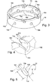
- the fixation system is designed to fix the implant in a stable and durable manner over time by means of the helicoidal screw 14 forming a spring with progressive turns and ending with a tip able to perforate the endothelium and to penetrate the muscle tissues. , so as to press the cardiac wall on the generally annular end face of the support 16, substantially at the same position (in the axial direction) as the internal bearing surface of the electrode system.
- the screw support 16 has on said front face 16c a series of recesses 16a which perform the function of irreversibility once in contact with the endothelium.
- the fastening system is inchtmontable: under the action of the screw 14 which acts as a tension spring achieving an axial retention force, the cardiac wall is pressed against the face 16c of the screw support 16 and s' anchor locally in the recesses (here six in number, regularly distributed) by the aforementioned spring effect.
- the six recesses define as many sharp edges, but shallow, in their region (in the circumferential direction) opposite to the screwing direction of the propeller and then realize six points. anchoring punctual and distributed on the endothelium (mutual spacing of 60 ° in this example), which ensure irreversibility of screwing done to anchor the capsule.
- a stimulation subassembly is shown here constituted by two electrodes 18 and 20 held by an electrode support 22 which also supports at its periphery a ring 24 for the diffusion of a steroid product.
- the support 22 is positioned coaxially with the screw support 16, inside thereof, and fixed by gluing or any other suitable means on a wall 12a closing the internal space of the capsule body 12 at its distal end on the screw side. , the support being located precisely thanks to a circular shoulder 12b provided on the outer face of said wall.
- the central pellet stimulation electrode 18 is fixed (by crimping, gluing, etc.) in the center of the support 22 and electrically connected to the internal electronics of the capsule housed in the body 12, via a micro-crossing.
- the second electrode 20 has the form of a washer positioned and fixed, for example by gluing, on the outer face of the support 22 and is also connected via a micro-crossing to the internal electronics.
- the ring 24 is impregnated with a steroid product such as dexamethasone and is positioned under the electrode 20.
- a steroid product such as dexamethasone
- the electronics associated with the electrodes make it possible to implement, in the case of cardiac stimulation, detection and stimulation functions, the structure described guaranteeing a reliable and permanent contact between the electrodes 18, 20 and the tissues.
- the helical screw 14 here consists of a wire with a diameter of the order of 0.5 mm, with a winding diameter typically about 5 mm and preferably identical to that of the body 12 of the device.
- the screw comprises a plane base followed by two contiguous turns and a final turn extending for example about 1.5 turn with interspire space of the same order of magnitude as the diameter of the wire.
- the free end of the screw 14 is refined, in this case by two machining in mutually orthogonal planes, thus creating a piercing tip 14a but not sharp. The purpose of this tip is to easily cross the endothelium and then enter the heart muscle while creating a minimum of tissue damage.
- the screw 14 is here made of implantable and biocompatible 316L stainless steel or any other equivalent material, which delivers a stiffness of about 0.1 N / mm (linear stiffness of the spring, measured by traction or compression with the aid of a dynamometer on a stroke of 1 mm).
- the electrode 18 contributes to the fixing of the capsule while ensuring reliable and continuous contact with the compressed tissues by means of the axial force of the screw 14 towards the support 16.
- Such a configuration is particularly suitable for low energy stimulation, with a needle length of the order of 1.2 mm and a diameter of the order of 0.4 mm, ie an active surface of the order of 1 mm 2 .
- the support 16 of the screw 14 has as indicated a face or bearing edge 16c, preferably of slightly rounded profile, from which are formed, in the oblique direction, six recesses 16a for making six protruding edges 165 very localized and very punctual (see in particular Figures 4 and 5 ) ensuring the irreversibility of the screwing of the capsule made as described above.
- the localized perforation of the endothelium is obtained by the projecting ridges 165, the other edges which form the boundaries of the notch being voluntarily very rounded so as not to propagate or enlarge the piercing of the endothelium during the unscrewing efforts.
- the relative area occupied by the recesses of the support face 16c represents 20 to 40% of this surface, and more preferably around 30%, which makes it possible to limit the traumatic effect of the projecting ridges 165 by limiting the penetration of the tissues in the recesses 16a, while ensuring a good attachment of said ridges 165 in the endothelium, and therefore the effectiveness of the anti-wear function.
- the dimensions of the recesses may vary.
- their width l may be of the order of 0.3 to 0.8 mm
- their depth or length L may be between 0.5 and 1 mm
- their inclination ⁇ may be between 20 and 60 °, and preferably close to 45 °.
- the recesses 16a defining the projecting ridges 165 are made in a biodegradable part attached to the support 16.
- the material used to make this insert can be in particular a bioabsorbable biopolymer such as a polylactide (PLA ), a polyglycolide (PGA) or a polylactide-coglycolide (PLGA), or any other equivalent material, implantable and resorbable in the body.
- PLA polylactide
- PGA polyglycolide
- PLGA polylactide-coglycolide
- the pointed electrode 18 has an enlarged head 18a, preferably of conical shape, joining at its base by a retracting annular shoulder 18b, a narrower rod 18c.
- the shoulder 18b provides a surface that mechanically strengthens the stability of the capsule on the cardiac wall, participating in the retention of compressed tissue by the axial force of the screw 14.
- the shoulder 18b has an annular width of the order of 0.2 mm. This value may vary according to the needs and dimensions of the capsule, typically between 0.05 and 1 mm.
- the angle of the cone is meanwhile between about 30 and 60 °, and typically close to 50 °.
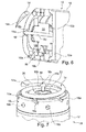
- the problem that solves this solution is to assemble a screw 14 stainless steel or other non-weldable material directly on the titanium case of the capsule.
- the support 16 has a configuration comprising a set of through orifices 16b, having a section corresponding approximately to that of the rods or tubes and for example circular, formed in the wall of the support 16, these orifices receiving rods or homologous tubes 14b formed at the periphery of the base of the screw 14, in corresponding angular locations.
- radial through orifices 16b are arranged in the support 16, which coincide with the portion of the contiguous turn screw.
- a rod or a tube 14b of the same material as the screw, or a laser weldable material to the material of the screw, is then inserted into each of these lateral holes.
- the bore of the tubes then opens on the turns of the screw.
- a laser shot through these holes then allows a direct weld tube / screw ensuring the requirements of a good laser welding, namely: i) compatibility of materials, ii) direct contact and iii) visual access for shooting and control quality.
- the screw 14 can be provided between the screw 14 and its support 16 a bayonet type mounting, the screw 14 then having at its base two rods or tubes such as 14b, preferably diametrically opposed, and the support 16 having in two diametrically opposed regions of the generally L-shaped notches 16d extending from the free face of the support 16 and allowing, before the laser welding, the mounting of the screw 14 by axial translation for the engagement of the rods or tubes in the notches, followed by a rotation to lock the rods or tubes to the bottom of the notches. There may then exist, in addition to these two notches, other notches 16d and / or other circular orifices 16b.
- step d) should not be understood in the narrow sense of a mechanical weld with fusion of the material of two separate parts, but an operation to collapse the material of the rod or tube inside the housing supporting the mechanical recoveries and strengthen the atraumatic function by removing the prominent forms.
- more orifices 16b or 16d are provided in number than the number of rods or tubes 14b of the screw 14. In this way, the orifices 16b or 16d remaining free make it possible to facilitate the diffusion of the steroid product delivered by the ring 24 radially. towards the heart wall.
- the notches 16d provided for such a bayonet type assembly are formed so as to participate in an anti-friction function as described above.
- the support 16 surrounds the base of the anchoring element, but alternately that the base of the anchoring element surrounds the support, in which case the skilled person will know how to do it. the necessary adaptations, particularly as regards the positioning of the rods or tubes 14b ensuring the attachment between the anchoring element and the support.
- the capsule can be placed by the practitioner according to the technique described in particular in the EP 2 394 695 A1 , and also extracted according to a known technique, the proximal portion 12 of the body of the capsule being arranged appropriately.
- the invention is not limited to the fixation of an autonomous stimulation capsule in a cardiac wall, but can be implemented for other implantable systems, whether autonomous or at the end of the probe, of the human body.
- the lengths of the helix and possibly the electrode can be easily adapted by the skilled person, without degrading the performance of fixation and irreversibility.
Landscapes
- Health & Medical Sciences (AREA)
- Engineering & Computer Science (AREA)
- Cardiology (AREA)
- Heart & Thoracic Surgery (AREA)
- Radiology & Medical Imaging (AREA)
- General Health & Medical Sciences (AREA)
- Veterinary Medicine (AREA)
- Public Health (AREA)
- Biomedical Technology (AREA)
- Nuclear Medicine, Radiotherapy & Molecular Imaging (AREA)
- Animal Behavior & Ethology (AREA)
- Life Sciences & Earth Sciences (AREA)
- Mechanical Engineering (AREA)
- Physics & Mathematics (AREA)
- Optics & Photonics (AREA)
- Chemical & Material Sciences (AREA)
- Medicinal Chemistry (AREA)
- Vascular Medicine (AREA)
- Bioinformatics & Cheminformatics (AREA)
- Plasma & Fusion (AREA)
- Prostheses (AREA)
- Electrotherapy Devices (AREA)
Applications Claiming Priority (1)
| Application Number | Priority Date | Filing Date | Title |
|---|---|---|---|
| FR1455896 | 2014-06-25 |
Publications (2)
| Publication Number | Publication Date |
|---|---|
| EP2959936A1 true EP2959936A1 (de) | 2015-12-30 |
| EP2959936B1 EP2959936B1 (de) | 2021-03-31 |
Family
ID=51862406
Family Applications (1)
| Application Number | Title | Priority Date | Filing Date |
|---|---|---|---|
| EP15167098.1A Active EP2959936B1 (de) | 2014-06-25 | 2015-05-11 | Implantierbare kapsel mit fixierung durch verschraubung, insbesondere autonome herzstimulationskapsel |
Country Status (2)
| Country | Link |
|---|---|
| US (1) | US9555236B2 (de) |
| EP (1) | EP2959936B1 (de) |
Families Citing this family (16)
| Publication number | Priority date | Publication date | Assignee | Title |
|---|---|---|---|---|
| WO2018094193A1 (en) | 2016-11-21 | 2018-05-24 | Cardiac Pacemakers, Inc. | Delivery devices and wall apposition sensing |
| US11198013B2 (en) | 2016-11-21 | 2021-12-14 | Cardiac Pacemakers, Inc. | Catheter and leadless cardiac devices including electrical pathway barrier |
| US10485981B2 (en) | 2016-12-27 | 2019-11-26 | Cardiac Pacemakers, Inc. | Fixation methods for leadless cardiac devices |
| US10806931B2 (en) | 2016-12-27 | 2020-10-20 | Cardiac Pacemakers, Inc. | Delivery devices and methods for leadless cardiac devices |
| AU2017387024B2 (en) | 2016-12-27 | 2020-04-09 | Cardiac Pacemakers, Inc. | Leadless delivery catheter with conductive pathway |
| WO2018136203A1 (en) | 2016-12-27 | 2018-07-26 | Cardiac Pacemakers, Inc. | Delivery devices and methods for leadless cardiac devices |
| AU2018211925B2 (en) | 2017-01-26 | 2020-02-27 | Cardiac Pacemakers, Inc. | Delivery devices for leadless cardiac devices |
| EP3592418B1 (de) | 2017-03-10 | 2023-08-23 | Cardiac Pacemakers, Inc. | Fixierung für leitungslose herzvorrichtungen |
| US10737092B2 (en) | 2017-03-30 | 2020-08-11 | Cardiac Pacemakers, Inc. | Delivery devices and methods for leadless cardiac devices |
| US11577085B2 (en) | 2017-08-03 | 2023-02-14 | Cardiac Pacemakers, Inc. | Delivery devices and methods for leadless cardiac devices |
| EP3946568A1 (de) | 2019-03-29 | 2022-02-09 | Cardiac Pacemakers, Inc. | Systeme und verfahren zur behandlung von herzrhythmusstörungen |
| EP3946556B1 (de) | 2019-03-29 | 2024-06-19 | Cardiac Pacemakers, Inc. | Systeme zur behandlung von herzrhythmusstörungen |
| US11510697B2 (en) | 2019-09-11 | 2022-11-29 | Cardiac Pacemakers, Inc. | Tools and systems for implanting and/or retrieving a leadless cardiac pacing device with helix fixation |
| US11571582B2 (en) | 2019-09-11 | 2023-02-07 | Cardiac Pacemakers, Inc. | Tools and systems for implanting and/or retrieving a leadless cardiac pacing device with helix fixation |
| US11684789B2 (en) * | 2020-01-27 | 2023-06-27 | Pacesetter, Inc. | Biostimulator header assembly having ceramic helix mount |
| WO2022152470A1 (en) * | 2021-01-15 | 2022-07-21 | Biotronik Se & Co. Kg | A medical implant anchoring element with improved characteristics for implantation and retention |
Citations (4)
| Publication number | Priority date | Publication date | Assignee | Title |
|---|---|---|---|---|
| WO2001026706A2 (en) * | 1999-10-13 | 2001-04-19 | Biocardia, Inc. | Drug delivery catheters that attach to tissue and methods for their use |
| US20080109042A1 (en) * | 2006-11-08 | 2008-05-08 | Cardiac Pacemakers, Inc. | Cardiac lead with a retractable helix |
| EP2394695A1 (de) | 2010-06-14 | 2011-12-14 | Sorin CRM SAS | Autonome intrakardiale Kapsel, und entsprechendes Implantationszubehör |
| WO2012051235A1 (en) | 2010-10-13 | 2012-04-19 | Nanostim, Inc. | Leadless cardiac pacemaker with anti-unscrewing feature |
Family Cites Families (4)
| Publication number | Priority date | Publication date | Assignee | Title |
|---|---|---|---|---|
| US5456708A (en) * | 1993-10-28 | 1995-10-10 | Pacesetter, Inc. | Rotatable pin, screw-in pacing and sensing lead having improved tip and fluidic seal |
| WO2005051483A2 (en) * | 2003-11-20 | 2005-06-09 | Angiotech International Ag | Electrical devices and anti-scarring agents |
| EP2537555B1 (de) * | 2011-06-24 | 2013-05-01 | Sorin CRM SAS | Autonomes Herzimplantat vom Typ leadless mit einem nicht ablösbaren Befestigungselement |
| US20130123872A1 (en) * | 2011-11-03 | 2013-05-16 | Pacesetter, Inc. | Leadless implantable medical device with dual chamber sensing functionality |
-
2015
- 2015-05-11 EP EP15167098.1A patent/EP2959936B1/de active Active
- 2015-06-19 US US14/744,916 patent/US9555236B2/en active Active
Patent Citations (4)
| Publication number | Priority date | Publication date | Assignee | Title |
|---|---|---|---|---|
| WO2001026706A2 (en) * | 1999-10-13 | 2001-04-19 | Biocardia, Inc. | Drug delivery catheters that attach to tissue and methods for their use |
| US20080109042A1 (en) * | 2006-11-08 | 2008-05-08 | Cardiac Pacemakers, Inc. | Cardiac lead with a retractable helix |
| EP2394695A1 (de) | 2010-06-14 | 2011-12-14 | Sorin CRM SAS | Autonome intrakardiale Kapsel, und entsprechendes Implantationszubehör |
| WO2012051235A1 (en) | 2010-10-13 | 2012-04-19 | Nanostim, Inc. | Leadless cardiac pacemaker with anti-unscrewing feature |
Also Published As
| Publication number | Publication date |
|---|---|
| US9555236B2 (en) | 2017-01-31 |
| US20160008594A1 (en) | 2016-01-14 |
| EP2959936B1 (de) | 2021-03-31 |
Similar Documents
| Publication | Publication Date | Title |
|---|---|---|
| EP2959940B1 (de) | Implantierbare Kapsel mit Fixierung durch Verschraubung, insbesondere autonome Herzstimulationskapsel | |
| EP2959936B1 (de) | Implantierbare kapsel mit fixierung durch verschraubung, insbesondere autonome herzstimulationskapsel | |
| EP3173126B1 (de) | Implantierbare kapsel, insbesondere autonome kapsel zur stimulation der herzfunktion, und entsprechendes montageverfahren | |
| EP2881141B1 (de) | Intrakardiale Kapsel, die in eine sehr dünne Wand, insbesondere die Septumwand, implantierbar ist | |
| EP2929910B1 (de) | Intrakardiale Kapsel und ihr Zubehör für die Explantation | |
| EP2384784B1 (de) | Einheit zur endokavitären Stimulation/Defibrillation des linken Herzventrikels | |
| EP2818202B1 (de) | Anschlusssystem zwischen einer medizinischen Vorrichtung und ihrem Implantationszubehörteil in situ | |
| EP2719424B1 (de) | Intraseptale Sonde zur Stimulation des linken Ventrikels | |
| EP3069754B1 (de) | In-situ-implantationszubehör für autonome intrakardiale kapsel | |
| FR2511251A1 (fr) | Pointe d'electrode poreuse pour stimulateur cardiaque et procede de fabrication | |
| FR2786701A1 (fr) | Systeme a conducteur electrique medical et a dispositif d'introduction, ensemble conducteur pour un tel systeme et son procede de fabrication | |
| US8126557B2 (en) | Lead connector pin and body assembly and method of manufacture | |
| CN109498995B (zh) | 用于可植入心脏设备的附接装置 | |
| FR3082434A1 (fr) | Implant cardiaque autonome de type "capsule leadless", comprenant un recuperateur d'energie a lame piezoelectrique | |
| EP3681589B1 (de) | Implantierbare autonome herzkapsel mit ausrichtbarem kopf und drehmomentbegrenzer | |
| EP0005106A2 (de) | In einer Höhlung des Herzens anzubringende Stimulationssonde | |
| FR2607013A1 (fr) | Sonde de stimulation cardiaque | |
| EP2574368A1 (de) | Sonde zur Multizonen-Epikardstimulation | |
| EP3058983A1 (de) | Mikrosonde zur detektion/stimulation, insbesondere für die mehrpunkt-neuromodulation des zentralen nervensystems | |
| EP4205799B1 (de) | Implantierbare medizinische vorrichtung mit atraumatischer spiralförmiger verankerungsschraube | |
| EP1036572B1 (de) | In Koronarvenen implantierbare Leitung zur Stimulation eines linken Herzvorhofs | |
| EP4059565B1 (de) | Autonom implantierbare und extrahierbare herzkapsel mit schwenkkopf und drehmomentbegrenzer | |
| FR2865409A1 (fr) | Sonde de defibrillation monocorps | |
| FR3087344A1 (fr) | Systeme d'accouplement entre une capsule cardiaque autonome et son outil d'implantation | |
| EP4346082B1 (de) | Auf piezoelektrischem blatt montierte trägheitsgewichtspendelanordnung, insbesondere für einen drahtlosen energierekuperator einer autonomen herzkapsel und ein entsprechendes verfahren zum zusammenbau |
Legal Events
| Date | Code | Title | Description |
|---|---|---|---|
| PUAI | Public reference made under article 153(3) epc to a published international application that has entered the european phase |
Free format text: ORIGINAL CODE: 0009012 |
|
| AK | Designated contracting states |
Kind code of ref document: A1 Designated state(s): AL AT BE BG CH CY CZ DE DK EE ES FI FR GB GR HR HU IE IS IT LI LT LU LV MC MK MT NL NO PL PT RO RS SE SI SK SM TR |
|
| AX | Request for extension of the european patent |
Extension state: BA ME |
|
| 17P | Request for examination filed |
Effective date: 20160523 |
|
| RBV | Designated contracting states (corrected) |
Designated state(s): AL AT BE BG CH CY CZ DE DK EE ES FI FR GB GR HR HU IE IS IT LI LT LU LV MC MK MT NL NO PL PT RO RS SE SI SK SM TR |
|
| STAA | Information on the status of an ep patent application or granted ep patent |
Free format text: STATUS: EXAMINATION IS IN PROGRESS |
|
| 17Q | First examination report despatched |
Effective date: 20191111 |
|
| GRAP | Despatch of communication of intention to grant a patent |
Free format text: ORIGINAL CODE: EPIDOSNIGR1 |
|
| STAA | Information on the status of an ep patent application or granted ep patent |
Free format text: STATUS: GRANT OF PATENT IS INTENDED |
|
| INTG | Intention to grant announced |
Effective date: 20201023 |
|
| GRAS | Grant fee paid |
Free format text: ORIGINAL CODE: EPIDOSNIGR3 |
|
| GRAA | (expected) grant |
Free format text: ORIGINAL CODE: 0009210 |
|
| STAA | Information on the status of an ep patent application or granted ep patent |
Free format text: STATUS: THE PATENT HAS BEEN GRANTED |
|
| AK | Designated contracting states |
Kind code of ref document: B1 Designated state(s): AL AT BE BG CH CY CZ DE DK EE ES FI FR GB GR HR HU IE IS IT LI LT LU LV MC MK MT NL NO PL PT RO RS SE SI SK SM TR |
|
| REG | Reference to a national code |
Ref country code: GB Ref legal event code: FG4D Free format text: NOT ENGLISH Ref country code: CH Ref legal event code: EP |
|
| REG | Reference to a national code |
Ref country code: AT Ref legal event code: REF Ref document number: 1376250 Country of ref document: AT Kind code of ref document: T Effective date: 20210415 Ref country code: DE Ref legal event code: R096 Ref document number: 602015067387 Country of ref document: DE |
|
| REG | Reference to a national code |
Ref country code: IE Ref legal event code: FG4D Free format text: LANGUAGE OF EP DOCUMENT: FRENCH |
|
| REG | Reference to a national code |
Ref country code: LT Ref legal event code: MG9D |
|
| PG25 | Lapsed in a contracting state [announced via postgrant information from national office to epo] |
Ref country code: FI Free format text: LAPSE BECAUSE OF FAILURE TO SUBMIT A TRANSLATION OF THE DESCRIPTION OR TO PAY THE FEE WITHIN THE PRESCRIBED TIME-LIMIT Effective date: 20210331 Ref country code: HR Free format text: LAPSE BECAUSE OF FAILURE TO SUBMIT A TRANSLATION OF THE DESCRIPTION OR TO PAY THE FEE WITHIN THE PRESCRIBED TIME-LIMIT Effective date: 20210331 Ref country code: BG Free format text: LAPSE BECAUSE OF FAILURE TO SUBMIT A TRANSLATION OF THE DESCRIPTION OR TO PAY THE FEE WITHIN THE PRESCRIBED TIME-LIMIT Effective date: 20210630 Ref country code: NO Free format text: LAPSE BECAUSE OF FAILURE TO SUBMIT A TRANSLATION OF THE DESCRIPTION OR TO PAY THE FEE WITHIN THE PRESCRIBED TIME-LIMIT Effective date: 20210630 |
|
| PG25 | Lapsed in a contracting state [announced via postgrant information from national office to epo] |
Ref country code: RS Free format text: LAPSE BECAUSE OF FAILURE TO SUBMIT A TRANSLATION OF THE DESCRIPTION OR TO PAY THE FEE WITHIN THE PRESCRIBED TIME-LIMIT Effective date: 20210331 Ref country code: LV Free format text: LAPSE BECAUSE OF FAILURE TO SUBMIT A TRANSLATION OF THE DESCRIPTION OR TO PAY THE FEE WITHIN THE PRESCRIBED TIME-LIMIT Effective date: 20210331 Ref country code: SE Free format text: LAPSE BECAUSE OF FAILURE TO SUBMIT A TRANSLATION OF THE DESCRIPTION OR TO PAY THE FEE WITHIN THE PRESCRIBED TIME-LIMIT Effective date: 20210331 |
|
| REG | Reference to a national code |
Ref country code: NL Ref legal event code: MP Effective date: 20210331 |
|
| REG | Reference to a national code |
Ref country code: AT Ref legal event code: MK05 Ref document number: 1376250 Country of ref document: AT Kind code of ref document: T Effective date: 20210331 |
|
| PG25 | Lapsed in a contracting state [announced via postgrant information from national office to epo] |
Ref country code: NL Free format text: LAPSE BECAUSE OF FAILURE TO SUBMIT A TRANSLATION OF THE DESCRIPTION OR TO PAY THE FEE WITHIN THE PRESCRIBED TIME-LIMIT Effective date: 20210331 Ref country code: LT Free format text: LAPSE BECAUSE OF FAILURE TO SUBMIT A TRANSLATION OF THE DESCRIPTION OR TO PAY THE FEE WITHIN THE PRESCRIBED TIME-LIMIT Effective date: 20210331 Ref country code: CZ Free format text: LAPSE BECAUSE OF FAILURE TO SUBMIT A TRANSLATION OF THE DESCRIPTION OR TO PAY THE FEE WITHIN THE PRESCRIBED TIME-LIMIT Effective date: 20210331 Ref country code: EE Free format text: LAPSE BECAUSE OF FAILURE TO SUBMIT A TRANSLATION OF THE DESCRIPTION OR TO PAY THE FEE WITHIN THE PRESCRIBED TIME-LIMIT Effective date: 20210331 Ref country code: AT Free format text: LAPSE BECAUSE OF FAILURE TO SUBMIT A TRANSLATION OF THE DESCRIPTION OR TO PAY THE FEE WITHIN THE PRESCRIBED TIME-LIMIT Effective date: 20210331 Ref country code: SM Free format text: LAPSE BECAUSE OF FAILURE TO SUBMIT A TRANSLATION OF THE DESCRIPTION OR TO PAY THE FEE WITHIN THE PRESCRIBED TIME-LIMIT Effective date: 20210331 |
|
| PG25 | Lapsed in a contracting state [announced via postgrant information from national office to epo] |
Ref country code: ES Free format text: LAPSE BECAUSE OF FAILURE TO SUBMIT A TRANSLATION OF THE DESCRIPTION OR TO PAY THE FEE WITHIN THE PRESCRIBED TIME-LIMIT Effective date: 20210331 Ref country code: PL Free format text: LAPSE BECAUSE OF FAILURE TO SUBMIT A TRANSLATION OF THE DESCRIPTION OR TO PAY THE FEE WITHIN THE PRESCRIBED TIME-LIMIT Effective date: 20210331 Ref country code: PT Free format text: LAPSE BECAUSE OF FAILURE TO SUBMIT A TRANSLATION OF THE DESCRIPTION OR TO PAY THE FEE WITHIN THE PRESCRIBED TIME-LIMIT Effective date: 20210802 Ref country code: SK Free format text: LAPSE BECAUSE OF FAILURE TO SUBMIT A TRANSLATION OF THE DESCRIPTION OR TO PAY THE FEE WITHIN THE PRESCRIBED TIME-LIMIT Effective date: 20210331 Ref country code: RO Free format text: LAPSE BECAUSE OF FAILURE TO SUBMIT A TRANSLATION OF THE DESCRIPTION OR TO PAY THE FEE WITHIN THE PRESCRIBED TIME-LIMIT Effective date: 20210331 Ref country code: IS Free format text: LAPSE BECAUSE OF FAILURE TO SUBMIT A TRANSLATION OF THE DESCRIPTION OR TO PAY THE FEE WITHIN THE PRESCRIBED TIME-LIMIT Effective date: 20210731 |
|
| REG | Reference to a national code |
Ref country code: CH Ref legal event code: PL |
|
| REG | Reference to a national code |
Ref country code: DE Ref legal event code: R097 Ref document number: 602015067387 Country of ref document: DE |
|
| PG25 | Lapsed in a contracting state [announced via postgrant information from national office to epo] |
Ref country code: MC Free format text: LAPSE BECAUSE OF FAILURE TO SUBMIT A TRANSLATION OF THE DESCRIPTION OR TO PAY THE FEE WITHIN THE PRESCRIBED TIME-LIMIT Effective date: 20210331 Ref country code: LU Free format text: LAPSE BECAUSE OF NON-PAYMENT OF DUE FEES Effective date: 20210511 Ref country code: LI Free format text: LAPSE BECAUSE OF NON-PAYMENT OF DUE FEES Effective date: 20210531 Ref country code: CH Free format text: LAPSE BECAUSE OF NON-PAYMENT OF DUE FEES Effective date: 20210531 Ref country code: AL Free format text: LAPSE BECAUSE OF FAILURE TO SUBMIT A TRANSLATION OF THE DESCRIPTION OR TO PAY THE FEE WITHIN THE PRESCRIBED TIME-LIMIT Effective date: 20210331 Ref country code: DK Free format text: LAPSE BECAUSE OF FAILURE TO SUBMIT A TRANSLATION OF THE DESCRIPTION OR TO PAY THE FEE WITHIN THE PRESCRIBED TIME-LIMIT Effective date: 20210331 |
|
| PLBE | No opposition filed within time limit |
Free format text: ORIGINAL CODE: 0009261 |
|
| STAA | Information on the status of an ep patent application or granted ep patent |
Free format text: STATUS: NO OPPOSITION FILED WITHIN TIME LIMIT |
|
| REG | Reference to a national code |
Ref country code: BE Ref legal event code: MM Effective date: 20210531 |
|
| 26N | No opposition filed |
Effective date: 20220104 |
|
| PG25 | Lapsed in a contracting state [announced via postgrant information from national office to epo] |
Ref country code: IE Free format text: LAPSE BECAUSE OF NON-PAYMENT OF DUE FEES Effective date: 20210511 |
|
| REG | Reference to a national code |
Ref country code: DE Ref legal event code: R082 Ref document number: 602015067387 Country of ref document: DE Representative=s name: PAGE, WHITE & FARRER GERMANY LLP, DE |
|
| PG25 | Lapsed in a contracting state [announced via postgrant information from national office to epo] |
Ref country code: IS Free format text: LAPSE BECAUSE OF FAILURE TO SUBMIT A TRANSLATION OF THE DESCRIPTION OR TO PAY THE FEE WITHIN THE PRESCRIBED TIME-LIMIT Effective date: 20210731 |
|
| PG25 | Lapsed in a contracting state [announced via postgrant information from national office to epo] |
Ref country code: BE Free format text: LAPSE BECAUSE OF NON-PAYMENT OF DUE FEES Effective date: 20210531 |
|
| PG25 | Lapsed in a contracting state [announced via postgrant information from national office to epo] |
Ref country code: HU Free format text: LAPSE BECAUSE OF FAILURE TO SUBMIT A TRANSLATION OF THE DESCRIPTION OR TO PAY THE FEE WITHIN THE PRESCRIBED TIME-LIMIT; INVALID AB INITIO Effective date: 20150511 |
|
| PG25 | Lapsed in a contracting state [announced via postgrant information from national office to epo] |
Ref country code: CY Free format text: LAPSE BECAUSE OF FAILURE TO SUBMIT A TRANSLATION OF THE DESCRIPTION OR TO PAY THE FEE WITHIN THE PRESCRIBED TIME-LIMIT Effective date: 20210331 |
|
| PG25 | Lapsed in a contracting state [announced via postgrant information from national office to epo] |
Ref country code: GR Free format text: LAPSE BECAUSE OF FAILURE TO SUBMIT A TRANSLATION OF THE DESCRIPTION OR TO PAY THE FEE WITHIN THE PRESCRIBED TIME-LIMIT Effective date: 20210331 |
|
| P01 | Opt-out of the competence of the unified patent court (upc) registered |
Effective date: 20230714 |
|
| PG25 | Lapsed in a contracting state [announced via postgrant information from national office to epo] |
Ref country code: MK Free format text: LAPSE BECAUSE OF FAILURE TO SUBMIT A TRANSLATION OF THE DESCRIPTION OR TO PAY THE FEE WITHIN THE PRESCRIBED TIME-LIMIT Effective date: 20210331 |
|
| PGFP | Annual fee paid to national office [announced via postgrant information from national office to epo] |
Ref country code: GB Payment date: 20240523 Year of fee payment: 10 |
|
| PGFP | Annual fee paid to national office [announced via postgrant information from national office to epo] |
Ref country code: DE Payment date: 20240513 Year of fee payment: 10 |
|
| PGFP | Annual fee paid to national office [announced via postgrant information from national office to epo] |
Ref country code: IT Payment date: 20240509 Year of fee payment: 10 Ref country code: FR Payment date: 20240524 Year of fee payment: 10 |
|
| PG25 | Lapsed in a contracting state [announced via postgrant information from national office to epo] |
Ref country code: MT Free format text: LAPSE BECAUSE OF FAILURE TO SUBMIT A TRANSLATION OF THE DESCRIPTION OR TO PAY THE FEE WITHIN THE PRESCRIBED TIME-LIMIT Effective date: 20210331 |