EP2959345B1 - Procede de decoupe d'un ou plusieurs vitrages - Google Patents
Procede de decoupe d'un ou plusieurs vitrages Download PDFInfo
- Publication number
- EP2959345B1 EP2959345B1 EP14718641.5A EP14718641A EP2959345B1 EP 2959345 B1 EP2959345 B1 EP 2959345B1 EP 14718641 A EP14718641 A EP 14718641A EP 2959345 B1 EP2959345 B1 EP 2959345B1
- Authority
- EP
- European Patent Office
- Prior art keywords
- glass
- cutting
- defects
- optimum
- plan
- Prior art date
- Legal status (The legal status is an assumption and is not a legal conclusion. Google has not performed a legal analysis and makes no representation as to the accuracy of the status listed.)
- Active
Links
Images


Classifications
-
- G—PHYSICS
- G05—CONTROLLING; REGULATING
- G05B—CONTROL OR REGULATING SYSTEMS IN GENERAL; FUNCTIONAL ELEMENTS OF SUCH SYSTEMS; MONITORING OR TESTING ARRANGEMENTS FOR SUCH SYSTEMS OR ELEMENTS
- G05B19/00—Program-control systems
- G05B19/02—Program-control systems electric
- G05B19/18—Numerical control [NC], i.e. automatically operating machines, in particular machine tools, e.g. in a manufacturing environment, so as to execute positioning, movement or co-ordinated operations by means of program data in numerical form
- G05B19/4097—Numerical control [NC], i.e. automatically operating machines, in particular machine tools, e.g. in a manufacturing environment, so as to execute positioning, movement or co-ordinated operations by means of program data in numerical form characterised by using design data to control NC machines, e.g. CAD/CAM
-
- B—PERFORMING OPERATIONS; TRANSPORTING
- B26—HAND CUTTING TOOLS; CUTTING; SEVERING
- B26D—CUTTING; DETAILS COMMON TO MACHINES FOR PERFORATING, PUNCHING, CUTTING-OUT, STAMPING-OUT OR SEVERING
- B26D5/00—Arrangements for operating and controlling machines or devices for cutting, cutting-out, stamping-out, punching, perforating, or severing by means other than cutting
- B26D5/005—Computer numerical control means
-
- B—PERFORMING OPERATIONS; TRANSPORTING
- B26—HAND CUTTING TOOLS; CUTTING; SEVERING
- B26D—CUTTING; DETAILS COMMON TO MACHINES FOR PERFORATING, PUNCHING, CUTTING-OUT, STAMPING-OUT OR SEVERING
- B26D1/00—Cutting through work characterised by the nature or movement of the cutting member or particular materials not otherwise provided for; Apparatus or machines therefor; Cutting members therefor
- B26D1/01—Cutting through work characterised by the nature or movement of the cutting member or particular materials not otherwise provided for; Apparatus or machines therefor; Cutting members therefor involving a cutting member which does not travel with the work
- B26D1/04—Cutting through work characterised by the nature or movement of the cutting member or particular materials not otherwise provided for; Apparatus or machines therefor; Cutting members therefor involving a cutting member which does not travel with the work having a linearly-movable cutting member
- B26D1/06—Cutting through work characterised by the nature or movement of the cutting member or particular materials not otherwise provided for; Apparatus or machines therefor; Cutting members therefor involving a cutting member which does not travel with the work having a linearly-movable cutting member wherein the cutting member reciprocates
- B26D1/08—Cutting through work characterised by the nature or movement of the cutting member or particular materials not otherwise provided for; Apparatus or machines therefor; Cutting members therefor involving a cutting member which does not travel with the work having a linearly-movable cutting member wherein the cutting member reciprocates of the guillotine type
- B26D1/085—Cutting through work characterised by the nature or movement of the cutting member or particular materials not otherwise provided for; Apparatus or machines therefor; Cutting members therefor involving a cutting member which does not travel with the work having a linearly-movable cutting member wherein the cutting member reciprocates of the guillotine type for thin material, e.g. for sheets, strips or the like
-
- C—CHEMISTRY; METALLURGY
- C03—GLASS; MINERAL OR SLAG WOOL
- C03B—MANUFACTURE, SHAPING, OR SUPPLEMENTARY PROCESSES
- C03B33/00—Severing cooled glass
- C03B33/02—Cutting or splitting sheet glass or ribbons; Apparatus or machines therefor
- C03B33/023—Cutting or splitting sheet glass or ribbons; Apparatus or machines therefor the sheet or ribbon being in a horizontal position
- C03B33/037—Controlling or regulating
-
- G—PHYSICS
- G05—CONTROLLING; REGULATING
- G05B—CONTROL OR REGULATING SYSTEMS IN GENERAL; FUNCTIONAL ELEMENTS OF SUCH SYSTEMS; MONITORING OR TESTING ARRANGEMENTS FOR SUCH SYSTEMS OR ELEMENTS
- G05B19/00—Program-control systems
- G05B19/02—Program-control systems electric
- G05B19/18—Numerical control [NC], i.e. automatically operating machines, in particular machine tools, e.g. in a manufacturing environment, so as to execute positioning, movement or co-ordinated operations by means of program data in numerical form
- G05B19/182—Numerical control [NC], i.e. automatically operating machines, in particular machine tools, e.g. in a manufacturing environment, so as to execute positioning, movement or co-ordinated operations by means of program data in numerical form characterised by the machine tool function, e.g. thread cutting, cam making, tool direction control
-
- G—PHYSICS
- G05—CONTROLLING; REGULATING
- G05B—CONTROL OR REGULATING SYSTEMS IN GENERAL; FUNCTIONAL ELEMENTS OF SUCH SYSTEMS; MONITORING OR TESTING ARRANGEMENTS FOR SUCH SYSTEMS OR ELEMENTS
- G05B2219/00—Program-control systems
- G05B2219/30—Nc systems
- G05B2219/35—Nc in input of data, input till input file format
- G05B2219/35162—Determine workpiece placement, nesting in blank, optimize, minimize loss material
-
- G—PHYSICS
- G05—CONTROLLING; REGULATING
- G05B—CONTROL OR REGULATING SYSTEMS IN GENERAL; FUNCTIONAL ELEMENTS OF SUCH SYSTEMS; MONITORING OR TESTING ARRANGEMENTS FOR SUCH SYSTEMS OR ELEMENTS
- G05B2219/00—Program-control systems
- G05B2219/30—Nc systems
- G05B2219/45—Nc applications
- G05B2219/45009—Glassforming
-
- Y—GENERAL TAGGING OF NEW TECHNOLOGICAL DEVELOPMENTS; GENERAL TAGGING OF CROSS-SECTIONAL TECHNOLOGIES SPANNING OVER SEVERAL SECTIONS OF THE IPC; TECHNICAL SUBJECTS COVERED BY FORMER USPC CROSS-REFERENCE ART COLLECTIONS [XRACs] AND DIGESTS
- Y02—TECHNOLOGIES OR APPLICATIONS FOR MITIGATION OR ADAPTATION AGAINST CLIMATE CHANGE
- Y02P—CLIMATE CHANGE MITIGATION TECHNOLOGIES IN THE PRODUCTION OR PROCESSING OF GOODS
- Y02P40/00—Technologies relating to the processing of minerals
- Y02P40/50—Glass production, e.g. reusing waste heat during processing or shaping
- Y02P40/57—Improving the yield, e-g- reduction of reject rates
-
- Y—GENERAL TAGGING OF NEW TECHNOLOGICAL DEVELOPMENTS; GENERAL TAGGING OF CROSS-SECTIONAL TECHNOLOGIES SPANNING OVER SEVERAL SECTIONS OF THE IPC; TECHNICAL SUBJECTS COVERED BY FORMER USPC CROSS-REFERENCE ART COLLECTIONS [XRACs] AND DIGESTS
- Y02—TECHNOLOGIES OR APPLICATIONS FOR MITIGATION OR ADAPTATION AGAINST CLIMATE CHANGE
- Y02P—CLIMATE CHANGE MITIGATION TECHNOLOGIES IN THE PRODUCTION OR PROCESSING OF GOODS
- Y02P80/00—Climate change mitigation technologies for sector-wide applications
- Y02P80/40—Minimising material used in manufacturing processes
Definitions
- the present invention relates to the field of cutting pieces of glass in glass trays of large dimensions.
- the glass is generally manufactured in the form of a continuous ribbon, for example a continuous ribbon of float glass or cast glass.
- This ribbon is then cut into glass trays called “motherglass” (literally “mother glass” in French even if this term is not used); which sheets are for example "PLF” (Large Format Glass Trays), typically of dimensions of 3.21m by about 6m or “DLF” of dimensions approximately 2.55m by 3.21m.
- PPF Large Format Glass Trays
- a defect analysis step is performed prior to this cutting to check whether the glass ribbon corresponds to defect specifications. If there are out-of-specification defaults, the motherglass is cut out by excluding a certain length of the ribbon corresponding to the off-specification portion of the ribbon.
- the defects are for example marked with an ink so as to identify them later without a new analysis.
- the motherglass can then be stacked in different piles according to the classes of specification of the defects.
- the motherglass can then undergo one or more transformation processes (for example depositing a layer, laminating, ).
- the motherglass are for example analyzed for possible defects and thus check whether the quality corresponds to a predetermined specification. Otherwise, the motherglass is rejected.
- US 2005/0023337 A discloses a method of cutting a continuous glass ribbon using a cutting plane with a single hierarchical cutting level.
- the method comprises a complementary optimization step of generating a cutting plane for a traverse on which an edge defect has been detected.
- this method is not useful for cutting motherglass because it includes only one hierarchical level of cutting.
- US-2004/0134231 discloses a method of cutting glass substrates for LCD screens in motherglass.
- the motherglass are identified and information regarding the defects of each motherglass such as position, size or type Defaults are stored in order to optimize the cutting of LCD substrates of different sizes according to the fault information of each motherglass.
- Different predetermined cutting planes are for example combined with different motherglass and with different acceptance criteria so as to maximize the number of LCD substrates that can be cut in a set of several motherglass.
- An object of the invention is to provide a method for reducing losses due to glass defects.
- glass tray means any glass sheet of finite and predetermined dimensions, whether it is a PLF or a DLF or a sheet of another size.
- cutting a glass tray means cutting a bare glass plate or on which a coating has been deposited.
- the method according to the invention has the advantage of making it possible to further optimize the process for cutting the pieces of glass in a large glass tray or in a group of several glass trays taking into account the defects in the glass.
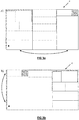
- the figure 1 represents, as a purely illustrative example, a first optimum optimum cutting plane for a monolithic glass tray.
- the pieces to be cut are indicated in gray and marked with a number preceded by a # and a number preceded by a C, while the falls are in light gray.
- the number preceded by a # is the cut sequence number, the number preceded by a C the carriage number to which the part is intended.
- guillotine cutting lines from one side of the piece to be cut
- the number of hierarchical levels is of any suitable type. It is for example four: X, Y, Z and V.
- the first level is said to have the lowest hierarchical rank (arbitrarily, it could also be the highest rank).
- the rank Y is of rank immediately superior to rank X.
- Rank Z is of rank immediately superior to rank Y.
- rank V is of rank immediately superior to rank Z.
- the denomination X, Y, Z, V is traditional but it can be any appropriate denomination.
- the cutting constraints described below are related to the fact that the guillotine cuts are defined by definition from one side of a tray or across, i.e. over its entire width or its entire length.
- the invention is specifically directed to cutting methods by guillotine.
- the hierarchical levels of guillotine cutting correspond to the guillotine cutting order.
- the cut lines of rank X are made before the cut lines of rank Y, themselves made before the cut lines of rank Z, etc.
- the row X cut lines are vertical, the horizontal Y row cut lines, the vertical Z row cut lines and the vertical V row cut lines.
- the X-ray cutting lines are horizontal, the vertical Y-shaped cutting lines, and so on.
- the different trolleys correspond to different trolleys on which the pieces are placed after cutting, i.e. to different manufacturing paths that the pieces will follow after cutting. This is their "referral" number.
- this first optimum cutting plane does not take into account any defects present in the glass. It was calculated based solely on criteria such as the size of pieces to be manufactured and in particular of their necessary order of manufacture.
- the optimization of the first cutting plane is of any type adapted to provide a first optimum cutting plane.
- the first cutting plane also takes into account defects, as explained further below.
- the invention is particular in that it provides a second optimization, taking into account defects and particularly fast.
- This second optimization is indeed intended to be performed very shortly before cutting (about a minute or less before cutting), so it must be effective in a very short period of time short. This is what the invention proposes.
- the second optimum cutting plane is obtained by automatically generating a cutting plane from the first optimum cutting plane and according to at least some of the information relating to defects. And most importantly, the generation includes cut-across permutations of the same hierarchical level within the glass plate (permutation between two X-axis crosses on the figure 2 ), for a fast execution of the optimization program.
- the implemented algorithm therefore consists of permuting different cut-offs (X, Y, Z & V for example on the figure 1 , according to the classic denomination of guillotine cutting) while respecting the possible constraints on the order of the cut pieces.
- the falls are then for example necessarily positioned on one end of a cross (or both) , or can be positioned in the middle if their size is sufficient.
- the order of this enumeration can be optimized and adjusted according to the properties of the traverses (number of falls, parts, surface of falls, etc.) in order to skew the exploration of the different permutations / crooked exchanges, as we will see with reference to Figures 3a) to 3d ).
- This is to accelerate the identification of a solution to eliminate all the defects, without having to go to the end of the enumeration in order to limit the calculation time which is limited by the character "real time" of the optimization of the cut.
- An empirical rule of choice of order of enumeration of the permutations to be realized in the optimization algorithm is understood by skew.
- the enumeration stops if it is not completed.
- the solution obtained will not necessarily be optimal but nevertheless at least equivalent or better than the solution provided by the first cutting plane. But above all, we understand the interest of the judicious choice of the order of enumeration of possible permutations.
- the maximum calculation time is of any type adapted to manufacturing time constraints.
- the defects are classified by severity according to their size, type (glass or layer), etc.
- a certain threshold which may vary depending on the application.
- the priority of elimination of these defects is fixed by their severity: the defect having the severity the stronger will be considered as a priority during optimization.
- the Figures 3a) to 3d ) illustrate an example to illustrate a possible implementation of the optimization algorithm.
- the bias is as follows: instead of taking the lexicographic order as indicated in the algorithm above for the order of enumeration of the permutations, we sort the crossings according to the surface of the greatest fall (at the surface ) they contain.
- the first optimum cutting plane and the second optimum cutting plane are those of one and the same glass plate. Optimization is performed independently for each glass tray.
- a complexity value is assigned to each of the first optimum cutting planes of each of said plurality of glass trays, the permutations between first (optimum) cutting planes being performed as a priority according to said complexity values.
- the complexity values are assigned according to at least one of: the number of falls, the area of the falls, the distribution of the falls in the different hierarchical levels of the guillotine cut.
- the permutations of the guillotine cutters are made at constant size and number of drops between the first optimum cutting plane and the second optimum cutting plane.
- the optimization algorithm makes it possible to rearrange the cutting plane by splitting the falls into subparts to increase the number of permutation possibilities.
- the permutations of the cut-off cuts are made with a constant drop surface between the first optimum cutting plane and the second optimum cutting plane. Indeed, a crosswheel permutation of the same levels does not change the drop surface.
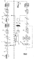
- FIG 4 is a diagram illustrating a non-limiting example of a manufacturing method to which the various aspects of the invention described above can be applied, so as to better understand the context in which the invention has been realized and in which the invention may apply.
- the upper part of the diagram concerns the steps of manufacturing a glass tray at a glass manufacturer on a first manufacturing site, and the lower part the steps of manufacturing an application glass such as a glass for automotive glazing, glazing for solar application, for example photovoltaic, glazing for OLED application, mirror or building glazing at a second manufacturer, customer of the first, on a second manufacturing site.
- an application glass such as a glass for automotive glazing, glazing for solar application, for example photovoltaic, glazing for OLED application, mirror or building glazing at a second manufacturer, customer of the first, on a second manufacturing site.
- One or more additional steps may be performed on the first and / or second site.
- all the manufacturing steps of the first manufacturer are illustrated as being performed on a single manufacturing site, it may be different sites, as well as the manufacturing steps performed at the second manufacturer.
- the second manufacturer is described as a customer of the first manufacturer, it may alternatively be a division or subsidiary of the first manufacturer.
- the first manufacturer produces in a plant 2 called "float glass", a continuous ribbon 4 of float glass on a bath of tin. Defects of the ribbon 4 are analyzed by a detection device 6 (of any suitable type), then the ribbon cut into glass trays 8 (also called “motherglass” or "PLF” for Plateau Large Format).
- a detection device 6 of any suitable type
- the detection device 6 is for example a device called “scanner” in the industry and intended to analyze the glass for defects.
- the attributes may include, for example, the thickness of the glass, the date of manufacture, the time of manufacture, the manufacturing site , the serial number of the manufacturing machine, the number of faults, the position of the faults, the type of defects, the density of defects, a criterion of severity of the fault, or any combination. This is not limiting.
- Other attributes of the glass ribbon can be stored in the database.
- the database 10 may be centralized or distributed and may include one or more sub-databases.
- the sub-databases can be connected to a main database and / or interconnected using different means of communication.
- the database and / or sub-databases can take various forms.
- the database and / or sub-databases can each take the shape of a portable storage unit (eg disk, CD-ROM, DVD-ROM, USB storage key, or other similar medium).
- defects is used here in the broad sense and is not limited to an imperfection in the glass tray. It can be a distinctive feature of glass. In addition, an imperfection may be in some cases acceptable and in other cases not be, for example depending on the intended application for the glass tray. Glass trays for the semiconductor field will for example be more sensitive to surface defects, while in the field of automotive or building glazing defects in transmission or reflection will be greater.
- the glass ribbon is cut into glass trays (motherglass) using a cutting device. Areas of the glass ribbon that have deficiencies that are considered unacceptable or outside standards or specifications may be eliminated during the cutting stage of the trays.
- a mapping device including the detection device, may be used to generate the attribute map, for example by scanning the glass ribbon 4 and recording the position and type of each defect present in the glass ribbon 4 in the database 10 which is maintained in a storage device.
- a severity criterion is also recorded in the database. This is a qualitative parameter providing a degree of severity of a defect.
- the severity criterion may be expressed as a distance between adjacent defects less than a predetermined value or a defect density of a certain size greater than a predetermined value.
- the information relating to the defects of each glass plate 8 is stored in the database 10.
- An identifier 12 for example a bar code, an RFID chip, or another identifier 12 of any suitable type is used to identify the glass plate 8.
- the marking of the identifier is for example made with an ink or a laser.
- the attributes map can take different forms. This is generally a file (including one or more subfiles), for example an electronic file, which includes for example the position, size and type of each defect of the glass tray 8 and / or the criterion of severity of the defect.
- the attribute map may also include additional information such as severity of the fault, the composition of the glass, the date of manufacture, etc.
- the attributes map is for example in the form of a table.
- the attributes of each tray can be stored in the database 10 in a storage medium such as a hard disk or a storage server. etc.
- the database 10 may be part of the computer system 21.
- the attributes may also be stored in an electronic memory, etc.
- the storage medium, including the hard disk, the storage server, the electronic memory, and so on. can be read using a computer in communication with the database 10 via a communication link.
- the communication link can be established via a live wire, via the Internet (“the cloud") or any other wireless network such as a cellular network.
- the glass trays 8 obtained are then arranged in a stack of glass trays 14.
- the trays stacks 14 can be stored in the form of pallets 16 of glass trays and transported to the treatment unit 18 for processing.
- the processing unit 18 may be located at a different location from the plant 2.
- the glass trays 16 are treated by the deposition of a coating to the For example, at least one layer or dielectric coating may be deposited on one or more of the glass trays.
- the glass trays 16 may be analyzed or inspected by a second detection device 20 (for example a scanner).
- the second detection device 20 is part of the mapping device. The analysis of the glass trays 16 by the device 20 allows the detection of additional defects that may have been generated during processing in the processing unit (for example, generated during the deposition process).
- the detection device 20 can still read the unique identifier on each of the glass trays 8. By identifying each tray 8 in the stack 16 of glass trays 8, the additional defects detected by the device 20 may be related to the identifier associated with the tray and added to the other defects of the corresponding glass tray. Therefore, in one embodiment, the database 10 is updated using the computer system 21 with information regarding any additional defects related to each glass tray 8.
- the glass trays 8 After treatment of the stack 16 of glass trays 8 at the processing unit and analyzing the glass trays 8 using the detection device 20, the glass trays 8 are stacked again in a stack 22 and stored in the warehouse 24.
- the warehouse 24 can be on the same site as the processing unit 18, or on a different site.
- the glass trays 8 can be arranged and stored based on the defect information present in the glass trays 8.
- the stacked and stored glass trays 8 can then be transported (for example, using trucks or trains, or any other means of transport) to the customer, ie the second glass manufacturer.
- the customer receives the stack 22 of glass trays 8 from the warehouse 24 and implements other processes on the glass trays to produce glass products. For example, the customer can cut the glass trays into several pieces of desired shapes or sizes. Cut glass pieces can have the same shape or different shapes. Similarly, cut glass pieces can have the same size or different dimensions, etc.
- a computer system 28 may be used to define the cutting edges of the glass pieces.
- the computer system 28 can execute a program that provides a first optimum cutting plane to produce desired pieces of glass while minimizing the amount of glass that is rejected and recycled due to the presence of defects that are out of specification and that are, for example, set by the second manufacturer or the end customer (for example, car manufacturer or window manufacturer, etc.)
- the program can be integrated into a readable medium by a coded machine with instructions to perform the operation cutting.
- the client or the second manufacturer uses a reader to read the identifier 12.
- the client can access the database 10 to retrieve information relating to the attributes of the glass tray 8, which are associated with the identifier 12.
- the computer system 28 is configured to access the database 10 to retrieve information relating to the attributes of the glass tray 8 having the identifier 12 which is read by the reader .
- the attributes include, among other parameters, the position of the defect, the criterion of difficulty and the criterion of gravity.
- the computer system 28 can access the database 10 through a network such as the Internet or via a dedicated communication line, or wireless communication (e.g. cellular communication).
- some information relating to the attributes of the glass tray is filtered using a filter 30.
- the filter 30 may be a computer program that is executable by the computer system 28, for example by a system processor. 28.
- the filter 30 may reside in the computer system 28 in one embodiment. Otherwise, the filter 30 may be distinct from the computer system 28. Because of the filter 30, the client does not have access to the complete database but only to a selected part of the database containing the attributes of the glass trays. 8.
- the amount of information that the customer can access is controlled by the first manufacturer using the filter 30. For example, the amount or level of information that can be accessed by the second manufacturer or a customer can be fixed by the first manufacturer according to a royalty amount or a fee or premium that the customer pays for the first manufacturer.
- the first manufacturer may define a plurality of access levels such as three access levels, a higher level, a medium level, and a lower level (for example, designated as platinum, gold, and the like). money in one embodiment) with the higher level (eg, platinum) giving access to the largest amount of information in the database and with the lowest level (eg, money) giving access to the smallest amount of information in the database.
- the customer can purchase rights to access the highest level (for example, platinum) by paying a higher premium.
- the customer can also purchase access rights only at the lower level (for example, money) by paying a lower premium.
- three levels are discussed in this document, it will be appreciated that any number of access levels may be provided in other embodiments.
- a level of access to the database 10 is provided for the client so as to allow the client to recover at least a portion of the attribute card of each tray in the stack of trays.
- the computer system comprises a computer product, for example a machine readable medium, which is encoded with machine readable instructions, and the attribute card can not be used by the machine.
- computer system 28 to provide an optimized cutting procedure for making the desired pieces of glass.
- the machine readable instructions prevent the user of the computer system 28 from retrieving, recording and / or displaying feature or attribute cards accessible by the computer system 28. In this way, the client is prevented collect information on defects in glass trays for data mining or statistical analysis.
- the first manufacturer builds a sub database of the database 10 that can be accessed by the intended customer based on the level of access acquired by the customer by paying a premium, or royalties.
- the sub-database contains information filtered using the filter 30. Therefore, the filter 30 can be configured by the first manufacturer to provide the sub-database according to the level of access acquired by the client. .
- the database data 10 may not be encrypted since the client does not have direct access to the database 10. Indeed, the client can only access and read the stored data in the sub-database that is customized according to the level of access acquired by the customer by paying a certain premium. Therefore, the client is not able to read all of the data or information stored in the database 10, but can simply read the data or information stored in the sub-database that is intended or provided. to the client.
- access to the database 10 may be provided to the client.
- the database data is encrypted. Encryption of the database can be achieved using appropriate known encryption algorithms. For example, the encryption can be performed using one or more processors of the computer system 21.
- the customer is provided with a specific key to read the specific data stored in the database 10. The key allows the customer to "unlock” and read the data that is intended only for the customer. The key does not allow the client to read other data stored in the database that is not intended for the customer. In other words, the access to the data contained in the database 10 is limited according to a desired level of access acquired by the customer by paying a premium.
- the key may be a password or other types of identification provided to the customer or a computer program (or link to a computer program) that enables the customer (eg, the computer system 28 that is designed to perform the job). cutting operation) to access the data in the database 10.
- the computer system 28 may also include a computer product, for example a machine readable medium, which is encoded with machine readable instructions so that the attribute card can not be used by the machine.
- computer system 28 only to provide an optimized cutting procedure for the production of the desired pieces of glass.
- the machine-readable instructions prevent the user of the computer system 28 from retrieving, recording and / or displaying feature or attribute cards accessible by the computer system 28. In this way, the client is prevented from collecting defect information on the glass trays for the purpose of performing data mining or statistical analysis.
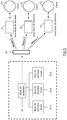
- the figure 5 is a schematic diagram showing an example of providing sub-databases to specific clients, according to one embodiment.
- the attributes of the glass trays 8 are stored in the database 10.
- the database 10 may comprise a plurality of local databases 10A, 10B and 10C, for example from different factories of the first manufacturer.
- the database 10 may be configured to communicate with local databases 10A, 10B, and 10C to retrieve the data stored therein.
- the database 10 may be hosted on a storage server that is configured to access the plurality of local databases and retrieve the data stored therein.
- a filter 30 may be used by the first manufacturer to provide a plurality of sub-databases 41, 42 and 43 from the database 10.
- the sub-database 41 can not be accessed by the client 51, the sub-database 42 can not be consulted by the client 52, and the sub-database 43 can not be consulted by the client 53.
- the filter 30 can be configured according to the level of access to acquired data. by each of the clients 51, 52 and 53.
- the filter 30 can be configured at level 1 to provide sub-bases 41 containing level 1 data (for example, silver level)
- the filter 30 can be configured at level 2 to provide sub-bases 42 containing the level 2 data (for example, gold level)
- the filter 30 may be configured at level 3 to provide sub bases 43 containing level 3 data (eg platinum level).
- level 1 may generate sub-databases 41 that contain a limited first portion of the attribute data.
- the sub-database 41 can only contain the position of the defects and not the characteristics of the defects such as the size or shape of the defect.
- the sub-database 42 may contain, in addition to the position of the defects, the size of the defects and the form of the defects.
- the sub-database 43 may contain, in addition to the position of the defects, the size and shape of the defects, the severity criterion, and so on. Therefore, level 3 is a higher level access giving access to more information and data in the database 10.
- the three levels are three acceptable levels of fault severity, so that more or less defects are transmitted to the client based on the expected quality.
- the sub-databases 41, 42 and 43 may be encrypted to prevent the respective clients 51, 52 and 53 from being able to perform statistical analyzes on the data stored in the databases. 41, 42 and 43.
- the client 51 may be able to read the data stored in the database 41 since the data stored in the database 41 is only used for cutting purposes. and not performing analysis of the data stored in the sub-database 41 to perform statistical analysis and extract statistical information on the attributes (e.g., defects) in the glass trays 8.
- the system The customer's computer 28 may include a computer product, for example a machine readable medium, encoded with machine executable instructions that allow the customer to read the data stored in the database. data (eg 41, 42, 43) to provide an optimized cutting procedure but prevents the user of the recovery system computer 28 from recording and / or displaying feature cards.
- the data is not encrypted at one time or another of the method and therefore readable by the client.
- the device still aims to prevent wild and large-scale data collection.
- the generation of the first and / or the second optimum cutting plane is performed on the basis of the data stored in the database, the data comprising attributes of each glass tray to be cut.
- Generating the cutting plan can be done either by the first manufacturer or by the customer or second manufacturer or by a third party independent of the first manufacturer and the second manufacturer.
- the third party may be, for example, a company that manufactures cutting devices or tools for cutting glass trays. Note that the first optimum cutting plane can also ignore defects, only the second cutting plane taking into account in this case.
- the first manufacturer may receive a specification (dimensions, shapes, etc.) of pieces of glass to be manufactured by the second manufacturer.
- the first manufacturer can use the constraints of shape and dimension and also use the attributes of the glass tray whose position of all defects, etc. to generate the first cutting plane or send a file to the customer containing the first cutting plane for the glass trays delivered to the customer.
- the database 10 is encrypted to ensure that the data stored in the database 10 are not accessible or only data for which the customer (second manufacturer) or a third party has paid are accessible.
- the first manufacturer simply provides the attributes purchased by the customer for the customer or a third party entity that in turn uses the data to generate the first optimum cut plan.
- the generation of the second optimum cutting plan is normally intended to be performed at the second manufacturer or customer or at least the manufacturer making the cutting of pieces of glass in the glass trays.
- the purpose of the second optimization is in fact to be performed at the closest (in time) of the cutting operation. It is typically performed by reading the identifiers of the glass trays less than a minute before positioning the glass tray corresponding on the cutting table, this to ensure that the glass tray for which the optimization is performed will actually be cut.
- the automatic generation of the second optimum cutting plane is for example calculated by the same computer system 28. Alternatively, however, it is another computer system, for example able to communicate with the computer system 28.
- the glass trays are cut by guillotine (ie along the entire width of the glass and in different successive orientations of different hierarchical level) according to the cutting plane that the computer system 28 has calculated for each tray
- the pieces of glass that are obtained after the cutting of the glass trays 8 can be washed 34.
- the chopped and washed glass pieces can be optionally analyzed by a third detection device 36 and then sent to the assembly, for example, to be mounted as automobile windows or windshields, or as windows of a building, etc.
- a third detection device 36 In an automobile windshield, two cut pieces of glass are curved and glued (i.e. laminated) together via a thermoplastic interlayer, for example PVB type.
- a glazing for the building two or three pieces of glass are assembled in a frame to form respectively a double or triple glazing, separated for example by gas strips, chosen for example from argon or air.
- the first optimum cutting plane is generated dynamically for each of the glass trays on the basis or not of the information concerning defects stored in the database 10.
- the figure 6 illustrates an example of a glass tray 8 for various defects that have been cataloged.
- the defects may include various types such as a "pinhole" which is a defect on the coating 61, a bubble defect 60, a scratch defect 62 on the glass, a surface defect 63.
- a Optimum cutting foreground for a single glass tray can be generated so as to obtain glass pieces of identical size.
- the glass tray has defects of a single type and size that are not acceptable in chopped (or "primitive") pieces of glass.
- an objective function of a plurality of representative quantities to be optimized is maximized or minimized. This is described for example in WO2012 / 164200 , patent application belonging to the applicant. Alternatively, however, we will use an algorithm and software of any type adapted to generate the first optimum cutting plan taking into account the size of the pieces to be cut and any manufacturing constraints.
- the shapes of the pieces of glass to be cut from the cutting plane may be rectangles, as can be seen in FIG. figure 4 .
- the pieces of glass to be cut can have any desired shape, for example a polygon, a circle, an ellipse, or any other more complex shape, as shown in FIG. figure 7 .
- the general shape of the pieces of glass to be cut can be polygonal, the pieces can be rounded or curved edges, as indicated on the figure 7 .
- some areas of the chopping pieces may have different fault acceptance criteria, as already explained above.
- a defect that is for example not acceptable in the center of the piece to be cut may for example be at its periphery. This is why, for example, different fault acceptance zones are defined on the glass pieces in order to carry out the second and possibly the first optimization. Examples of areas are illustrated on the figure 7 .
- the process represented on the figure 1 can be generalized to manufacturing processes of any suitable type.
- the number of steps of the defect analysis is not limited to the steps illustrated here, but includes any number of steps adapted to the manufacturing constraints.
- the identifiers 12 may be provided on a glass tray wafer 8. In this manner, the identifier 12 on each of the glass trays 8 can be read even if the glass trays are stacked together.
- the defects can be marked with an ink of a predetermined color. , with predetermined characters or symbols on the defect itself or in the vicinity of the defect. The customer will then be able to identify the different types of defects, the size and position of the defects and can generate fault information that is useful for the cutting plan optimization program (s).
- the cutting of the guillotine glass trays is first performed vertically along the width of the glass tray 8 for all cutting lines of the first hierarchical level (rank X) and then horizontally along the width of the cut cut-out for all the cutting lines of the second hierarchical level, and so on for the upper rows of cuts.
- the lowest hierarchical level cuts are made horizontally along the length of the glass tray 8 and then vertically and so on.
- a method for identifying defects in the glass comprises identifying, using an identification device, each of the plurality of glass trays with an identifier, and generating, using a mapping device, an attribute map for each glass of the plurality of glass trays.
- the method further comprises associating, using a computer system, the attribute map of each of the plurality of glass trays with the corresponding identifier of each of the plurality of glass trays. ; storing the feature map of each glass of the glass trays in a database, and providing to a client with a level of access to the information in the database so as to allow the client to recover at least one part of the attribute card of the glass trays acquired by the customer.
- the application programs for executing the methods may be in the form of programs in a computer, such as a personal computer or a server computer, or in a distributed computing environment comprising a plurality of computers.
- the computer may include, for example, a desktop computer, a laptop, a handheld computing device such as a PDA, etc.
- the computer program products may comprise a computer-readable medium or storage medium or a medium having stored instructions thereon for programming a computer to perform the methods described above. Examples of suitable storage media include any type of disk, including floppy disks, optical disks, DVDs, CD-ROMs, magnetic optical disks, rams, EPROMs, EEPROMs, magnetic or optical cards, hard disks, flash cards (e.g.
- USB flash drive card a USB flash drive card
- card PCMCIA memory a USB flash drive card
- smart card a USB flash drive card
- some or all of the computer program product can be downloaded from a remote computer system or a computer server via a network such as the Internet, an ATM network, a wide area network (WAN), or a network. local.
- a network such as the Internet, an ATM network, a wide area network (WAN), or a network. local.
- Programs are stored on one or more computer-readable media.
- Programs may include software to control both the hardware of a general-purpose or specialized computer or a processor.
- the software also allows the computer or processor to interact with a user via output devices such as a graphical user interface, HMD, etc.
- the software may also include, but not be limited to, drivers of devices, operating systems, and user applications.
Landscapes
- Engineering & Computer Science (AREA)
- Chemical & Material Sciences (AREA)
- Human Computer Interaction (AREA)
- Automation & Control Theory (AREA)
- General Physics & Mathematics (AREA)
- Physics & Mathematics (AREA)
- Manufacturing & Machinery (AREA)
- Life Sciences & Earth Sciences (AREA)
- Mechanical Engineering (AREA)
- Forests & Forestry (AREA)
- Organic Chemistry (AREA)
- Materials Engineering (AREA)
- General Engineering & Computer Science (AREA)
- Re-Forming, After-Treatment, Cutting And Transporting Of Glass Products (AREA)
- Numerical Control (AREA)
- General Factory Administration (AREA)
Priority Applications (1)
| Application Number | Priority Date | Filing Date | Title |
|---|---|---|---|
| PL14718641T PL2959345T3 (pl) | 2013-02-22 | 2014-02-24 | Sposób cięcia jednej lub wielu tafli szkła |
Applications Claiming Priority (2)
| Application Number | Priority Date | Filing Date | Title |
|---|---|---|---|
| FR1351541A FR3002529B1 (fr) | 2013-02-22 | 2013-02-22 | Procede de decoupe d'un ou plusieurs vitrages |
| PCT/FR2014/050386 WO2014128424A1 (fr) | 2013-02-22 | 2014-02-24 | Procede de decoupe d'un ou plusieurs vitrages |
Publications (2)
| Publication Number | Publication Date |
|---|---|
| EP2959345A1 EP2959345A1 (fr) | 2015-12-30 |
| EP2959345B1 true EP2959345B1 (fr) | 2019-12-11 |
Family
ID=49001001
Family Applications (1)
| Application Number | Title | Priority Date | Filing Date |
|---|---|---|---|
| EP14718641.5A Active EP2959345B1 (fr) | 2013-02-22 | 2014-02-24 | Procede de decoupe d'un ou plusieurs vitrages |
Country Status (12)
| Country | Link |
|---|---|
| US (1) | US9669558B2 (pl) |
| EP (1) | EP2959345B1 (pl) |
| JP (1) | JP6434426B2 (pl) |
| KR (1) | KR102186386B1 (pl) |
| CN (1) | CN104995572B (pl) |
| BR (1) | BR112015019990B1 (pl) |
| EA (1) | EA028992B1 (pl) |
| ES (1) | ES2768427T3 (pl) |
| FR (1) | FR3002529B1 (pl) |
| PL (1) | PL2959345T3 (pl) |
| PT (1) | PT2959345T (pl) |
| WO (1) | WO2014128424A1 (pl) |
Families Citing this family (32)
| Publication number | Priority date | Publication date | Assignee | Title |
|---|---|---|---|---|
| ITUB20153518A1 (it) * | 2015-09-10 | 2017-03-10 | Bottero Spa | Metodo per la realizzazione di spezzoni di lastra di vetro marchiati |
| FR3055718B1 (fr) * | 2016-09-07 | 2025-07-18 | Saint Gobain | Procede et dispositif d'optimisation d'un plan de decoupe par guillotine de pieces de verre |
| CN108073778B (zh) * | 2016-11-07 | 2022-03-04 | 上海宝信软件股份有限公司 | 提高fcl机组成品率的自动切割方法及系统 |
| JP6765639B2 (ja) * | 2016-12-26 | 2020-10-07 | 日本電気硝子株式会社 | ガラス板の製造方法 |
| WO2018185855A1 (ja) * | 2017-04-04 | 2018-10-11 | 株式会社Mujin | 制御装置、ピッキングシステム、物流システム、プログラム、制御方法、及び、生産方法 |
| JP6444499B1 (ja) | 2017-04-04 | 2018-12-26 | 株式会社Mujin | 制御装置、ピッキングシステム、物流システム、プログラム、及び、制御方法 |
| DE112017007394B4 (de) | 2017-04-04 | 2020-12-03 | Mujin, Inc. | Informationsverarbeitungsvorrichtung, Greifsystem, Verteilersystem, Programm und Informationsverarbeitungsverfahren |
| JP6258557B1 (ja) | 2017-04-04 | 2018-01-10 | 株式会社Mujin | 制御装置、ピッキングシステム、物流システム、プログラム、制御方法、及び、生産方法 |
| CN115385039A (zh) | 2017-04-04 | 2022-11-25 | 牧今科技 | 控制装置、信息处理装置、控制方法以及信息处理方法 |
| CN107140817B (zh) * | 2017-06-01 | 2021-01-12 | 东旭光电科技股份有限公司 | 用于基板玻璃加工的方法、控制器和设备 |
| DE102017128394B4 (de) * | 2017-11-30 | 2019-10-17 | Held-Systems Gmbh | Verfahren zum Schneiden von Schnitt-Teilen und Vorrichtung zum Schneiden |
| CN108255138A (zh) * | 2017-12-06 | 2018-07-06 | 洛阳兰迪玻璃机器股份有限公司 | 一种玻璃深加工连线控制方法 |
| FR3075782B1 (fr) | 2017-12-21 | 2022-07-22 | Saint Gobain | Procede et dispositif de generation d'une sequence de plans de decoupe d'une sequence de pieces de verre dans une sequence de feuilles de verre |
| CN108593897A (zh) * | 2018-07-12 | 2018-09-28 | 浙江罗克光电科技有限公司 | 一种用于光学蓝玻璃的检测设备 |
| DE102018213280A1 (de) * | 2018-08-08 | 2020-02-13 | Sms Group Gmbh | Qualitätsoptimierter Zuschnitt von Metallbändern |
| CN108943179B (zh) * | 2018-08-22 | 2021-09-28 | 慧泉智能科技(苏州)有限公司 | 一种针对木材表面缺陷的最优切割方法 |
| FR3092421B1 (fr) | 2019-01-31 | 2022-07-22 | Saint Gobain | Procédé de lecture manuelle d’un code, et dispositif de lecture pour la mise en œuvre dudit procédé |
| FR3099152B1 (fr) * | 2019-07-26 | 2021-07-23 | Saint Gobain | Procédé et système de génération d’un plan de découpe d’un produit verrier complexe |
| CN110790500B (zh) * | 2019-10-29 | 2022-04-22 | 河源旗滨硅业有限公司 | 玻璃板的切割方法、装置及终端设备 |
| CN111410414B (zh) * | 2020-04-27 | 2022-03-29 | 江西财经大学 | 一种玻璃切割优化技术的实现方法 |
| EP3961477B1 (en) | 2020-08-24 | 2023-06-07 | Saint-Gobain Glass France | Method for detecting and reading a matrix code marked on a glass substrate |
| BE1028865B1 (nl) * | 2020-12-09 | 2022-07-12 | Dovy Keukens Nv | Werkwijze voor het verwerken van een natuursteen paneel en productie van een keuken- of kastenconstructie |
| CN113213745B (zh) * | 2021-03-24 | 2022-09-27 | 重庆惠科金渝光电科技有限公司 | 一种切割机及其切割方法 |
| CN113222212B (zh) * | 2021-04-07 | 2023-04-07 | 杭州玖欣物联科技有限公司 | 一种提升玻璃切割利用率的方法 |
| CN118302392A (zh) * | 2021-11-17 | 2024-07-05 | 康宁公司 | 用于处理玻璃带的方法和装置 |
| CN114565168B (zh) * | 2022-03-03 | 2022-09-02 | 广东工业大学 | 一种面向带缺陷矩形板材的排样下料方法及系统 |
| CN115180813A (zh) * | 2022-06-21 | 2022-10-14 | 中国建材国际工程集团有限公司 | 一种药用中性硼硅玻璃切割方法 |
| CN114800660B (zh) * | 2022-06-27 | 2022-09-30 | 浙江双元科技股份有限公司 | 一种用于片材分切的缺陷定位系统及方法 |
| CN115648361B (zh) * | 2022-10-31 | 2023-12-01 | 中栎住研(山东)环保材料有限公司 | 软木玻璃纤维复合材料板材的制备方法及系统 |
| KR102869999B1 (ko) * | 2023-09-07 | 2025-10-13 | 주식회사 엘엑스세미콘 | 고유코드가 구비된 전력반도체 모듈용 방열 기판의 제조방법 및 고유코드가 구비된 방열 기판을 포함하는 전력반도체 모듈의 제조방법 |
| KR102908632B1 (ko) * | 2023-09-07 | 2026-01-08 | 주식회사 엘엑스세미콘 | 고유코드가 구비된 방열 기판용 세라믹 기판, 고유코드가 구비된 전력반도체 모듈용 방열 기판, 고유코드가 구비된 방열 기판을 포함하는 전력반도체 모듈 |
| FR3155225A1 (fr) | 2023-11-13 | 2025-05-16 | Saint-Gobain Glass France | Procédé de détermination d’au moins une zone de la surface d’un plateau de verre |
Family Cites Families (11)
| Publication number | Priority date | Publication date | Assignee | Title |
|---|---|---|---|---|
| JP4347067B2 (ja) * | 2002-04-03 | 2009-10-21 | AvanStrate株式会社 | マザーガラスの欠陥検査方法及び装置並びに液晶表示装置用ガラス基板の製造方法 |
| US20040236458A1 (en) * | 2003-05-20 | 2004-11-25 | Clayton Byron C. | Glass optimization |
| US7206656B2 (en) * | 2003-05-20 | 2007-04-17 | Ged Integrated Solutions, Inc. | Glass optimization |
| DE10335247B4 (de) * | 2003-08-01 | 2005-12-01 | Schott Ag | Verfahren und Vorrichtung zum Abtrennen von Glasplatten |
| US7167767B2 (en) * | 2003-08-22 | 2007-01-23 | Ged Integrated Solutions, Inc. | Glass production sequencing |
| JP4671610B2 (ja) * | 2004-02-17 | 2011-04-20 | カワサキプラントシステムズ株式会社 | 板ガラスの割断システム |
| WO2009055135A2 (en) * | 2007-08-22 | 2009-04-30 | Hp3 Software, Inc. | A glass production line having dynamic production control and a tempering furnace with a dedicated delivery device and a method of controlling a glass production line tempering furnace |
| DE102007043567B3 (de) * | 2007-09-13 | 2008-10-02 | Grenzebach Maschinenbau Gmbh | Vorrichtung und Verfahren zum Trennen von Glasplatten |
| US8895892B2 (en) * | 2008-10-23 | 2014-11-25 | Corning Incorporated | Non-contact glass shearing device and method for scribing or cutting a moving glass sheet |
| FR2975687A1 (fr) | 2011-05-27 | 2012-11-30 | Saint Gobain | Procede de decoupe d'un ou plusieurs vitrages |
| EA201591045A1 (ru) * | 2012-11-28 | 2015-10-30 | Сэн-Гобэн Гласс Франс | Способ и система идентификации дефектов стекла |
-
2013
- 2013-02-22 FR FR1351541A patent/FR3002529B1/fr active Active
-
2014
- 2014-02-24 US US14/769,557 patent/US9669558B2/en active Active
- 2014-02-24 JP JP2015558535A patent/JP6434426B2/ja active Active
- 2014-02-24 KR KR1020157022829A patent/KR102186386B1/ko active Active
- 2014-02-24 WO PCT/FR2014/050386 patent/WO2014128424A1/fr not_active Ceased
- 2014-02-24 PT PT147186415T patent/PT2959345T/pt unknown
- 2014-02-24 ES ES14718641T patent/ES2768427T3/es active Active
- 2014-02-24 BR BR112015019990-9A patent/BR112015019990B1/pt active IP Right Grant
- 2014-02-24 EA EA201591550A patent/EA028992B1/ru not_active IP Right Cessation
- 2014-02-24 PL PL14718641T patent/PL2959345T3/pl unknown
- 2014-02-24 CN CN201480009836.6A patent/CN104995572B/zh active Active
- 2014-02-24 EP EP14718641.5A patent/EP2959345B1/fr active Active
Non-Patent Citations (1)
| Title |
|---|
| None * |
Also Published As
| Publication number | Publication date |
|---|---|
| US9669558B2 (en) | 2017-06-06 |
| PT2959345T (pt) | 2020-02-24 |
| PL2959345T3 (pl) | 2020-06-01 |
| US20150375415A1 (en) | 2015-12-31 |
| CN104995572B (zh) | 2018-02-23 |
| BR112015019990B1 (pt) | 2022-07-19 |
| EP2959345A1 (fr) | 2015-12-30 |
| ES2768427T3 (es) | 2020-06-22 |
| FR3002529B1 (fr) | 2015-02-20 |
| JP6434426B2 (ja) | 2018-12-05 |
| KR20150120998A (ko) | 2015-10-28 |
| EA028992B1 (ru) | 2018-01-31 |
| FR3002529A1 (fr) | 2014-08-29 |
| JP2016514081A (ja) | 2016-05-19 |
| BR112015019990A2 (pt) | 2017-07-18 |
| CN104995572A (zh) | 2015-10-21 |
| WO2014128424A1 (fr) | 2014-08-28 |
| EA201591550A1 (ru) | 2015-12-30 |
| KR102186386B1 (ko) | 2020-12-03 |
Similar Documents
| Publication | Publication Date | Title |
|---|---|---|
| EP2959345B1 (fr) | Procede de decoupe d'un ou plusieurs vitrages | |
| EP2714602A1 (fr) | Procede de decoupe d'un ou plusieurs vitrages | |
| EP3105063B1 (fr) | Feuille de verre avec code d'identification | |
| FR2975688A1 (fr) | Procede de decoupe d'un ou plusieurs vitrages | |
| KR20190090039A (ko) | 유리에서 결함을 식별하기 위한 방법 및 시스템 | |
| FR2753801A1 (fr) | Procede et appareil pour l'identification automatique des coupes de defauts dans des donnees sismiques utilisant une structure horizon temps | |
| EP3727769A1 (fr) | Procédé et dispositif de génération d'une séquence de plans de découpe d'une séquence de pièces de verre dans une séquence de feuilles de verre | |
| EP4070265A1 (fr) | Méthode mise en uvre par ordinateur pour l'allocation d'une pièce comptable à un couple de comptes débiteur/créditeur et l'écriture comptable | |
| FR3141452A1 (fr) | Procédé de préparation d'une unité de charge logistique à emballer | |
| FR3141546A1 (fr) | Procédé de sélection d’emballages optimisés en fonction d’unités de charge logistique | |
| WO2025103986A1 (fr) | Procédé de détermination d'au moins une zone de la surface d'un plateau de verre | |
| FR3141453A1 (fr) | Procédé d’affectation d’un emballage à une unité de charge logistique | |
| FR3141547A1 (fr) | procédé de détermination d’un plan d’agencement de contenus dans un contenant | |
| EP4608725A1 (fr) | Procédé de détermination d'un plan d'agencement de contenus dans un contenant | |
| FR3159030A1 (fr) | Procede de classification de chutes previsionnelles longitudinales de matiere dans un procede de fabrication industrielle, systeme associe | |
| WO2025036922A1 (fr) | Procede de classification de chutes previsionnelles de matiere dans un procede de fabrication industrielle, systeme associe | |
| CA3146448A1 (fr) | Procede et systeme de generation d'un plan de decoupe d'un produit verrier complexe | |
| Viaud | Mathematical programming methods for complex cutting problems | |
| WO2024156875A1 (fr) | Procédé et système de détermination du type de verre composant un élément verrier | |
| FR3040906B1 (fr) | Procede de realisation d'un plateau en planches | |
| FR2970100A1 (fr) | Procede de generation d'un carnet d'adresses consolide |
Legal Events
| Date | Code | Title | Description |
|---|---|---|---|
| PUAI | Public reference made under article 153(3) epc to a published international application that has entered the european phase |
Free format text: ORIGINAL CODE: 0009012 |
|
| 17P | Request for examination filed |
Effective date: 20150922 |
|
| AK | Designated contracting states |
Kind code of ref document: A1 Designated state(s): AL AT BE BG CH CY CZ DE DK EE ES FI FR GB GR HR HU IE IS IT LI LT LU LV MC MK MT NL NO PL PT RO RS SE SI SK SM TR |
|
| AX | Request for extension of the european patent |
Extension state: BA ME |
|
| DAX | Request for extension of the european patent (deleted) | ||
| STAA | Information on the status of an ep patent application or granted ep patent |
Free format text: STATUS: EXAMINATION IS IN PROGRESS |
|
| 17Q | First examination report despatched |
Effective date: 20190301 |
|
| GRAP | Despatch of communication of intention to grant a patent |
Free format text: ORIGINAL CODE: EPIDOSNIGR1 |
|
| STAA | Information on the status of an ep patent application or granted ep patent |
Free format text: STATUS: GRANT OF PATENT IS INTENDED |
|
| INTG | Intention to grant announced |
Effective date: 20190717 |
|
| GRAS | Grant fee paid |
Free format text: ORIGINAL CODE: EPIDOSNIGR3 |
|
| GRAA | (expected) grant |
Free format text: ORIGINAL CODE: 0009210 |
|
| STAA | Information on the status of an ep patent application or granted ep patent |
Free format text: STATUS: THE PATENT HAS BEEN GRANTED |
|
| AK | Designated contracting states |
Kind code of ref document: B1 Designated state(s): AL AT BE BG CH CY CZ DE DK EE ES FI FR GB GR HR HU IE IS IT LI LT LU LV MC MK MT NL NO PL PT RO RS SE SI SK SM TR |
|
| REG | Reference to a national code |
Ref country code: GB Ref legal event code: FG4D Free format text: NOT ENGLISH |
|
| REG | Reference to a national code |
Ref country code: CH Ref legal event code: EP |
|
| REG | Reference to a national code |
Ref country code: AT Ref legal event code: REF Ref document number: 1212825 Country of ref document: AT Kind code of ref document: T Effective date: 20191215 |
|
| REG | Reference to a national code |
Ref country code: DE Ref legal event code: R096 Ref document number: 602014058193 Country of ref document: DE |
|
| REG | Reference to a national code |
Ref country code: IE Ref legal event code: FG4D Free format text: LANGUAGE OF EP DOCUMENT: FRENCH |
|
| REG | Reference to a national code |
Ref country code: RO Ref legal event code: EPE |
|
| REG | Reference to a national code |
Ref country code: PT Ref legal event code: SC4A Ref document number: 2959345 Country of ref document: PT Date of ref document: 20200224 Kind code of ref document: T Free format text: AVAILABILITY OF NATIONAL TRANSLATION Effective date: 20200214 |
|
| REG | Reference to a national code |
Ref country code: SE Ref legal event code: TRGR |
|
| REG | Reference to a national code |
Ref country code: LT Ref legal event code: MG4D |
|
| PG25 | Lapsed in a contracting state [announced via postgrant information from national office to epo] |
Ref country code: LT Free format text: LAPSE BECAUSE OF FAILURE TO SUBMIT A TRANSLATION OF THE DESCRIPTION OR TO PAY THE FEE WITHIN THE PRESCRIBED TIME-LIMIT Effective date: 20191211 Ref country code: BG Free format text: LAPSE BECAUSE OF FAILURE TO SUBMIT A TRANSLATION OF THE DESCRIPTION OR TO PAY THE FEE WITHIN THE PRESCRIBED TIME-LIMIT Effective date: 20200311 Ref country code: FI Free format text: LAPSE BECAUSE OF FAILURE TO SUBMIT A TRANSLATION OF THE DESCRIPTION OR TO PAY THE FEE WITHIN THE PRESCRIBED TIME-LIMIT Effective date: 20191211 Ref country code: LV Free format text: LAPSE BECAUSE OF FAILURE TO SUBMIT A TRANSLATION OF THE DESCRIPTION OR TO PAY THE FEE WITHIN THE PRESCRIBED TIME-LIMIT Effective date: 20191211 Ref country code: GR Free format text: LAPSE BECAUSE OF FAILURE TO SUBMIT A TRANSLATION OF THE DESCRIPTION OR TO PAY THE FEE WITHIN THE PRESCRIBED TIME-LIMIT Effective date: 20200312 Ref country code: NO Free format text: LAPSE BECAUSE OF FAILURE TO SUBMIT A TRANSLATION OF THE DESCRIPTION OR TO PAY THE FEE WITHIN THE PRESCRIBED TIME-LIMIT Effective date: 20200311 |
|
| REG | Reference to a national code |
Ref country code: NL Ref legal event code: FP |
|
| PG25 | Lapsed in a contracting state [announced via postgrant information from national office to epo] |
Ref country code: RS Free format text: LAPSE BECAUSE OF FAILURE TO SUBMIT A TRANSLATION OF THE DESCRIPTION OR TO PAY THE FEE WITHIN THE PRESCRIBED TIME-LIMIT Effective date: 20191211 Ref country code: HR Free format text: LAPSE BECAUSE OF FAILURE TO SUBMIT A TRANSLATION OF THE DESCRIPTION OR TO PAY THE FEE WITHIN THE PRESCRIBED TIME-LIMIT Effective date: 20191211 |
|
| REG | Reference to a national code |
Ref country code: SK Ref legal event code: T3 Ref document number: E 33616 Country of ref document: SK |
|
| RAP2 | Party data changed (patent owner data changed or rights of a patent transferred) |
Owner name: SAINT-GOBAIN GLASS FRANCE |
|
| REG | Reference to a national code |
Ref country code: ES Ref legal event code: FG2A Ref document number: 2768427 Country of ref document: ES Kind code of ref document: T3 Effective date: 20200622 |
|
| PG25 | Lapsed in a contracting state [announced via postgrant information from national office to epo] |
Ref country code: AL Free format text: LAPSE BECAUSE OF FAILURE TO SUBMIT A TRANSLATION OF THE DESCRIPTION OR TO PAY THE FEE WITHIN THE PRESCRIBED TIME-LIMIT Effective date: 20191211 |
|
| PG25 | Lapsed in a contracting state [announced via postgrant information from national office to epo] |
Ref country code: EE Free format text: LAPSE BECAUSE OF FAILURE TO SUBMIT A TRANSLATION OF THE DESCRIPTION OR TO PAY THE FEE WITHIN THE PRESCRIBED TIME-LIMIT Effective date: 20191211 |
|
| PG25 | Lapsed in a contracting state [announced via postgrant information from national office to epo] |
Ref country code: IS Free format text: LAPSE BECAUSE OF FAILURE TO SUBMIT A TRANSLATION OF THE DESCRIPTION OR TO PAY THE FEE WITHIN THE PRESCRIBED TIME-LIMIT Effective date: 20200411 Ref country code: SM Free format text: LAPSE BECAUSE OF FAILURE TO SUBMIT A TRANSLATION OF THE DESCRIPTION OR TO PAY THE FEE WITHIN THE PRESCRIBED TIME-LIMIT Effective date: 20191211 |
|
| REG | Reference to a national code |
Ref country code: DE Ref legal event code: R097 Ref document number: 602014058193 Country of ref document: DE |
|
| REG | Reference to a national code |
Ref country code: CH Ref legal event code: PL |
|
| REG | Reference to a national code |
Ref country code: AT Ref legal event code: MK05 Ref document number: 1212825 Country of ref document: AT Kind code of ref document: T Effective date: 20191211 |
|
| PLBE | No opposition filed within time limit |
Free format text: ORIGINAL CODE: 0009261 |
|
| STAA | Information on the status of an ep patent application or granted ep patent |
Free format text: STATUS: NO OPPOSITION FILED WITHIN TIME LIMIT |
|
| PG25 | Lapsed in a contracting state [announced via postgrant information from national office to epo] |
Ref country code: DK Free format text: LAPSE BECAUSE OF FAILURE TO SUBMIT A TRANSLATION OF THE DESCRIPTION OR TO PAY THE FEE WITHIN THE PRESCRIBED TIME-LIMIT Effective date: 20191211 Ref country code: MC Free format text: LAPSE BECAUSE OF FAILURE TO SUBMIT A TRANSLATION OF THE DESCRIPTION OR TO PAY THE FEE WITHIN THE PRESCRIBED TIME-LIMIT Effective date: 20191211 |
|
| 26N | No opposition filed |
Effective date: 20200914 |
|
| PG25 | Lapsed in a contracting state [announced via postgrant information from national office to epo] |
Ref country code: SI Free format text: LAPSE BECAUSE OF FAILURE TO SUBMIT A TRANSLATION OF THE DESCRIPTION OR TO PAY THE FEE WITHIN THE PRESCRIBED TIME-LIMIT Effective date: 20191211 Ref country code: AT Free format text: LAPSE BECAUSE OF FAILURE TO SUBMIT A TRANSLATION OF THE DESCRIPTION OR TO PAY THE FEE WITHIN THE PRESCRIBED TIME-LIMIT Effective date: 20191211 Ref country code: LI Free format text: LAPSE BECAUSE OF NON-PAYMENT OF DUE FEES Effective date: 20200229 Ref country code: CH Free format text: LAPSE BECAUSE OF NON-PAYMENT OF DUE FEES Effective date: 20200229 |
|
| PG25 | Lapsed in a contracting state [announced via postgrant information from national office to epo] |
Ref country code: IE Free format text: LAPSE BECAUSE OF NON-PAYMENT OF DUE FEES Effective date: 20200224 |
|
| PG25 | Lapsed in a contracting state [announced via postgrant information from national office to epo] |
Ref country code: MT Free format text: LAPSE BECAUSE OF FAILURE TO SUBMIT A TRANSLATION OF THE DESCRIPTION OR TO PAY THE FEE WITHIN THE PRESCRIBED TIME-LIMIT Effective date: 20191211 Ref country code: CY Free format text: LAPSE BECAUSE OF FAILURE TO SUBMIT A TRANSLATION OF THE DESCRIPTION OR TO PAY THE FEE WITHIN THE PRESCRIBED TIME-LIMIT Effective date: 20191211 |
|
| PG25 | Lapsed in a contracting state [announced via postgrant information from national office to epo] |
Ref country code: MK Free format text: LAPSE BECAUSE OF FAILURE TO SUBMIT A TRANSLATION OF THE DESCRIPTION OR TO PAY THE FEE WITHIN THE PRESCRIBED TIME-LIMIT Effective date: 20191211 |
|
| P01 | Opt-out of the competence of the unified patent court (upc) registered |
Effective date: 20230515 |
|
| PGFP | Annual fee paid to national office [announced via postgrant information from national office to epo] |
Ref country code: PL Payment date: 20241223 Year of fee payment: 12 |
|
| PGFP | Annual fee paid to national office [announced via postgrant information from national office to epo] |
Ref country code: PT Payment date: 20250221 Year of fee payment: 12 Ref country code: DE Payment date: 20241231 Year of fee payment: 12 |
|
| PGFP | Annual fee paid to national office [announced via postgrant information from national office to epo] |
Ref country code: RO Payment date: 20250123 Year of fee payment: 12 |
|
| PGFP | Annual fee paid to national office [announced via postgrant information from national office to epo] |
Ref country code: ES Payment date: 20250307 Year of fee payment: 12 |
|
| PGFP | Annual fee paid to national office [announced via postgrant information from national office to epo] |
Ref country code: SE Payment date: 20250103 Year of fee payment: 12 |
|
| PGFP | Annual fee paid to national office [announced via postgrant information from national office to epo] |
Ref country code: BE Payment date: 20250107 Year of fee payment: 12 |
|
| PGFP | Annual fee paid to national office [announced via postgrant information from national office to epo] |
Ref country code: CZ Payment date: 20250129 Year of fee payment: 12 |
|
| PGFP | Annual fee paid to national office [announced via postgrant information from national office to epo] |
Ref country code: SK Payment date: 20250113 Year of fee payment: 12 Ref country code: IT Payment date: 20250110 Year of fee payment: 12 Ref country code: GB Payment date: 20250102 Year of fee payment: 12 |
|
| PGFP | Annual fee paid to national office [announced via postgrant information from national office to epo] |
Ref country code: TR Payment date: 20250206 Year of fee payment: 12 |
|
| PGFP | Annual fee paid to national office [announced via postgrant information from national office to epo] |
Ref country code: FR Payment date: 20251231 Year of fee payment: 13 |
|
| PGFP | Annual fee paid to national office [announced via postgrant information from national office to epo] |
Ref country code: NL Payment date: 20260106 Year of fee payment: 13 |
|
| PGFP | Annual fee paid to national office [announced via postgrant information from national office to epo] |
Ref country code: LU Payment date: 20260216 Year of fee payment: 13 |