EP2959230B1 - Perfectionnements de systèmes de transfert de chaleur solaire thermodynamiques - Google Patents
Perfectionnements de systèmes de transfert de chaleur solaire thermodynamiques Download PDFInfo
- Publication number
- EP2959230B1 EP2959230B1 EP13786730.5A EP13786730A EP2959230B1 EP 2959230 B1 EP2959230 B1 EP 2959230B1 EP 13786730 A EP13786730 A EP 13786730A EP 2959230 B1 EP2959230 B1 EP 2959230B1
- Authority
- EP
- European Patent Office
- Prior art keywords
- panel
- heat transfer
- refrigerant
- transfer system
- hot
- Prior art date
- Legal status (The legal status is an assumption and is not a legal conclusion. Google has not performed a legal analysis and makes no representation as to the accuracy of the status listed.)
- Active
Links
- XLYOFNOQVPJJNP-UHFFFAOYSA-N water Substances O XLYOFNOQVPJJNP-UHFFFAOYSA-N 0.000 claims description 46
- 239000003507 refrigerant Substances 0.000 claims description 39
- 238000010438 heat treatment Methods 0.000 claims description 24
- 239000012530 fluid Substances 0.000 claims description 19
- 239000007788 liquid Substances 0.000 claims description 6
- XAGFODPZIPBFFR-UHFFFAOYSA-N aluminium Chemical compound [Al] XAGFODPZIPBFFR-UHFFFAOYSA-N 0.000 claims description 4
- 229910052782 aluminium Inorganic materials 0.000 claims description 4
- 239000004411 aluminium Substances 0.000 claims description 4
- LVGUZGTVOIAKKC-UHFFFAOYSA-N 1,1,1,2-tetrafluoroethane Chemical compound FCC(F)(F)F LVGUZGTVOIAKKC-UHFFFAOYSA-N 0.000 claims description 3
- 238000012544 monitoring process Methods 0.000 claims description 2
- 230000009182 swimming Effects 0.000 description 6
- 238000001816 cooling Methods 0.000 description 5
- 241000589248 Legionella Species 0.000 description 3
- 230000008901 benefit Effects 0.000 description 3
- 208000007764 Legionnaires' Disease Diseases 0.000 description 2
- 239000000853 adhesive Substances 0.000 description 2
- 230000001070 adhesive effect Effects 0.000 description 2
- 230000000694 effects Effects 0.000 description 2
- 230000007613 environmental effect Effects 0.000 description 2
- 241001465754 Metazoa Species 0.000 description 1
- 238000004378 air conditioning Methods 0.000 description 1
- 238000007710 freezing Methods 0.000 description 1
- 230000008014 freezing Effects 0.000 description 1
- 239000008236 heating water Substances 0.000 description 1
- 238000009434 installation Methods 0.000 description 1
- 238000001556 precipitation Methods 0.000 description 1
Images


Classifications
-
- F—MECHANICAL ENGINEERING; LIGHTING; HEATING; WEAPONS; BLASTING
- F24—HEATING; RANGES; VENTILATING
- F24D—DOMESTIC- OR SPACE-HEATING SYSTEMS, e.g. CENTRAL HEATING SYSTEMS; DOMESTIC HOT-WATER SUPPLY SYSTEMS; ELEMENTS OR COMPONENTS THEREFOR
- F24D15/00—Other domestic- or space-heating systems
- F24D15/04—Other domestic- or space-heating systems using heat pumps
-
- F—MECHANICAL ENGINEERING; LIGHTING; HEATING; WEAPONS; BLASTING
- F24—HEATING; RANGES; VENTILATING
- F24D—DOMESTIC- OR SPACE-HEATING SYSTEMS, e.g. CENTRAL HEATING SYSTEMS; DOMESTIC HOT-WATER SUPPLY SYSTEMS; ELEMENTS OR COMPONENTS THEREFOR
- F24D17/00—Domestic hot-water supply systems
- F24D17/0015—Domestic hot-water supply systems using solar energy
-
- F—MECHANICAL ENGINEERING; LIGHTING; HEATING; WEAPONS; BLASTING
- F24—HEATING; RANGES; VENTILATING
- F24D—DOMESTIC- OR SPACE-HEATING SYSTEMS, e.g. CENTRAL HEATING SYSTEMS; DOMESTIC HOT-WATER SUPPLY SYSTEMS; ELEMENTS OR COMPONENTS THEREFOR
- F24D11/00—Central heating systems using heat accumulated in storage masses
- F24D11/02—Central heating systems using heat accumulated in storage masses using heat pumps
- F24D11/0214—Central heating systems using heat accumulated in storage masses using heat pumps water heating system
-
- F—MECHANICAL ENGINEERING; LIGHTING; HEATING; WEAPONS; BLASTING
- F24—HEATING; RANGES; VENTILATING
- F24D—DOMESTIC- OR SPACE-HEATING SYSTEMS, e.g. CENTRAL HEATING SYSTEMS; DOMESTIC HOT-WATER SUPPLY SYSTEMS; ELEMENTS OR COMPONENTS THEREFOR
- F24D17/00—Domestic hot-water supply systems
- F24D17/02—Domestic hot-water supply systems using heat pumps
-
- F—MECHANICAL ENGINEERING; LIGHTING; HEATING; WEAPONS; BLASTING
- F24—HEATING; RANGES; VENTILATING
- F24D—DOMESTIC- OR SPACE-HEATING SYSTEMS, e.g. CENTRAL HEATING SYSTEMS; DOMESTIC HOT-WATER SUPPLY SYSTEMS; ELEMENTS OR COMPONENTS THEREFOR
- F24D19/00—Details
- F24D19/0095—Devices for preventing damage by freezing
-
- F—MECHANICAL ENGINEERING; LIGHTING; HEATING; WEAPONS; BLASTING
- F24—HEATING; RANGES; VENTILATING
- F24D—DOMESTIC- OR SPACE-HEATING SYSTEMS, e.g. CENTRAL HEATING SYSTEMS; DOMESTIC HOT-WATER SUPPLY SYSTEMS; ELEMENTS OR COMPONENTS THEREFOR
- F24D19/00—Details
- F24D19/10—Arrangement or mounting of control or safety devices
- F24D19/1006—Arrangement or mounting of control or safety devices for water heating systems
- F24D19/1009—Arrangement or mounting of control or safety devices for water heating systems for central heating
- F24D19/1045—Arrangement or mounting of control or safety devices for water heating systems for central heating the system uses a heat pump and solar energy
-
- F—MECHANICAL ENGINEERING; LIGHTING; HEATING; WEAPONS; BLASTING
- F24—HEATING; RANGES; VENTILATING
- F24D—DOMESTIC- OR SPACE-HEATING SYSTEMS, e.g. CENTRAL HEATING SYSTEMS; DOMESTIC HOT-WATER SUPPLY SYSTEMS; ELEMENTS OR COMPONENTS THEREFOR
- F24D19/00—Details
- F24D19/10—Arrangement or mounting of control or safety devices
- F24D19/1006—Arrangement or mounting of control or safety devices for water heating systems
- F24D19/1066—Arrangement or mounting of control or safety devices for water heating systems for the combination of central heating and domestic hot water
- F24D19/1072—Arrangement or mounting of control or safety devices for water heating systems for the combination of central heating and domestic hot water the system uses a heat pump
-
- F—MECHANICAL ENGINEERING; LIGHTING; HEATING; WEAPONS; BLASTING
- F24—HEATING; RANGES; VENTILATING
- F24D—DOMESTIC- OR SPACE-HEATING SYSTEMS, e.g. CENTRAL HEATING SYSTEMS; DOMESTIC HOT-WATER SUPPLY SYSTEMS; ELEMENTS OR COMPONENTS THEREFOR
- F24D3/00—Hot-water central heating systems
- F24D3/08—Hot-water central heating systems in combination with systems for domestic hot-water supply
- F24D3/082—Hot water storage tanks specially adapted therefor
-
- F—MECHANICAL ENGINEERING; LIGHTING; HEATING; WEAPONS; BLASTING
- F24—HEATING; RANGES; VENTILATING
- F24D—DOMESTIC- OR SPACE-HEATING SYSTEMS, e.g. CENTRAL HEATING SYSTEMS; DOMESTIC HOT-WATER SUPPLY SYSTEMS; ELEMENTS OR COMPONENTS THEREFOR
- F24D3/00—Hot-water central heating systems
- F24D3/18—Hot-water central heating systems using heat pumps
-
- F—MECHANICAL ENGINEERING; LIGHTING; HEATING; WEAPONS; BLASTING
- F24—HEATING; RANGES; VENTILATING
- F24F—AIR-CONDITIONING; AIR-HUMIDIFICATION; VENTILATION; USE OF AIR CURRENTS FOR SCREENING
- F24F11/00—Control or safety arrangements
- F24F11/30—Control or safety arrangements for purposes related to the operation of the system, e.g. for safety or monitoring
- F24F11/41—Defrosting; Preventing freezing
- F24F11/42—Defrosting; Preventing freezing of outdoor units
-
- F—MECHANICAL ENGINEERING; LIGHTING; HEATING; WEAPONS; BLASTING
- F24—HEATING; RANGES; VENTILATING
- F24F—AIR-CONDITIONING; AIR-HUMIDIFICATION; VENTILATION; USE OF AIR CURRENTS FOR SCREENING
- F24F5/00—Air-conditioning systems or apparatus not covered by F24F1/00 or F24F3/00, e.g. using solar heat or combined with household units such as an oven or water heater
- F24F5/0071—Air-conditioning systems or apparatus not covered by F24F1/00 or F24F3/00, e.g. using solar heat or combined with household units such as an oven or water heater adapted for use in covered swimming pools
-
- F—MECHANICAL ENGINEERING; LIGHTING; HEATING; WEAPONS; BLASTING
- F24—HEATING; RANGES; VENTILATING
- F24F—AIR-CONDITIONING; AIR-HUMIDIFICATION; VENTILATION; USE OF AIR CURRENTS FOR SCREENING
- F24F5/00—Air-conditioning systems or apparatus not covered by F24F1/00 or F24F3/00, e.g. using solar heat or combined with household units such as an oven or water heater
- F24F5/0096—Air-conditioning systems or apparatus not covered by F24F1/00 or F24F3/00, e.g. using solar heat or combined with household units such as an oven or water heater combined with domestic apparatus
-
- F—MECHANICAL ENGINEERING; LIGHTING; HEATING; WEAPONS; BLASTING
- F24—HEATING; RANGES; VENTILATING
- F24H—FLUID HEATERS, e.g. WATER OR AIR HEATERS, HAVING HEAT-GENERATING MEANS, e.g. HEAT PUMPS, IN GENERAL
- F24H1/00—Water heaters, e.g. boilers, continuous-flow heaters or water-storage heaters
- F24H1/48—Water heaters for central heating incorporating heaters for domestic water
- F24H1/50—Water heaters for central heating incorporating heaters for domestic water incorporating domestic water tanks
-
- F—MECHANICAL ENGINEERING; LIGHTING; HEATING; WEAPONS; BLASTING
- F24—HEATING; RANGES; VENTILATING
- F24H—FLUID HEATERS, e.g. WATER OR AIR HEATERS, HAVING HEAT-GENERATING MEANS, e.g. HEAT PUMPS, IN GENERAL
- F24H15/00—Control of fluid heaters
- F24H15/20—Control of fluid heaters characterised by control inputs
-
- F—MECHANICAL ENGINEERING; LIGHTING; HEATING; WEAPONS; BLASTING
- F24—HEATING; RANGES; VENTILATING
- F24H—FLUID HEATERS, e.g. WATER OR AIR HEATERS, HAVING HEAT-GENERATING MEANS, e.g. HEAT PUMPS, IN GENERAL
- F24H15/00—Control of fluid heaters
- F24H15/40—Control of fluid heaters characterised by the type of controllers
- F24H15/414—Control of fluid heaters characterised by the type of controllers using electronic processing, e.g. computer-based
-
- F—MECHANICAL ENGINEERING; LIGHTING; HEATING; WEAPONS; BLASTING
- F24—HEATING; RANGES; VENTILATING
- F24H—FLUID HEATERS, e.g. WATER OR AIR HEATERS, HAVING HEAT-GENERATING MEANS, e.g. HEAT PUMPS, IN GENERAL
- F24H4/00—Fluid heaters characterised by the use of heat pumps
- F24H4/02—Water heaters
- F24H4/04—Storage heaters
-
- F—MECHANICAL ENGINEERING; LIGHTING; HEATING; WEAPONS; BLASTING
- F25—REFRIGERATION OR COOLING; COMBINED HEATING AND REFRIGERATION SYSTEMS; HEAT PUMP SYSTEMS; MANUFACTURE OR STORAGE OF ICE; LIQUEFACTION SOLIDIFICATION OF GASES
- F25B—REFRIGERATION MACHINES, PLANTS OR SYSTEMS; COMBINED HEATING AND REFRIGERATION SYSTEMS; HEAT PUMP SYSTEMS
- F25B30/00—Heat pumps
- F25B30/02—Heat pumps of the compression type
-
- F—MECHANICAL ENGINEERING; LIGHTING; HEATING; WEAPONS; BLASTING
- F28—HEAT EXCHANGE IN GENERAL
- F28F—DETAILS OF HEAT-EXCHANGE AND HEAT-TRANSFER APPARATUS, OF GENERAL APPLICATION
- F28F21/00—Constructions of heat-exchange apparatus characterised by the selection of particular materials
- F28F21/08—Constructions of heat-exchange apparatus characterised by the selection of particular materials of metal
- F28F21/081—Heat exchange elements made from metals or metal alloys
- F28F21/084—Heat exchange elements made from metals or metal alloys from aluminium or aluminium alloys
-
- F—MECHANICAL ENGINEERING; LIGHTING; HEATING; WEAPONS; BLASTING
- F28—HEAT EXCHANGE IN GENERAL
- F28F—DETAILS OF HEAT-EXCHANGE AND HEAT-TRANSFER APPARATUS, OF GENERAL APPLICATION
- F28F21/00—Constructions of heat-exchange apparatus characterised by the selection of particular materials
- F28F21/08—Constructions of heat-exchange apparatus characterised by the selection of particular materials of metal
- F28F21/088—Constructions of heat-exchange apparatus characterised by the selection of particular materials of metal for domestic or space-heating systems
-
- F—MECHANICAL ENGINEERING; LIGHTING; HEATING; WEAPONS; BLASTING
- F28—HEAT EXCHANGE IN GENERAL
- F28F—DETAILS OF HEAT-EXCHANGE AND HEAT-TRANSFER APPARATUS, OF GENERAL APPLICATION
- F28F3/00—Plate-like or laminated elements; Assemblies of plate-like or laminated elements
- F28F3/12—Elements constructed in the shape of a hollow panel, e.g. with channels
- F28F3/14—Elements constructed in the shape of a hollow panel, e.g. with channels by separating portions of a pair of joined sheets to form channels, e.g. by inflation
-
- F—MECHANICAL ENGINEERING; LIGHTING; HEATING; WEAPONS; BLASTING
- F24—HEATING; RANGES; VENTILATING
- F24D—DOMESTIC- OR SPACE-HEATING SYSTEMS, e.g. CENTRAL HEATING SYSTEMS; DOMESTIC HOT-WATER SUPPLY SYSTEMS; ELEMENTS OR COMPONENTS THEREFOR
- F24D2220/00—Components of central heating installations excluding heat sources
- F24D2220/06—Heat exchangers
-
- F—MECHANICAL ENGINEERING; LIGHTING; HEATING; WEAPONS; BLASTING
- F25—REFRIGERATION OR COOLING; COMBINED HEATING AND REFRIGERATION SYSTEMS; HEAT PUMP SYSTEMS; MANUFACTURE OR STORAGE OF ICE; LIQUEFACTION SOLIDIFICATION OF GASES
- F25B—REFRIGERATION MACHINES, PLANTS OR SYSTEMS; COMBINED HEATING AND REFRIGERATION SYSTEMS; HEAT PUMP SYSTEMS
- F25B2339/00—Details of evaporators; Details of condensers
- F25B2339/04—Details of condensers
- F25B2339/047—Water-cooled condensers
-
- F—MECHANICAL ENGINEERING; LIGHTING; HEATING; WEAPONS; BLASTING
- F25—REFRIGERATION OR COOLING; COMBINED HEATING AND REFRIGERATION SYSTEMS; HEAT PUMP SYSTEMS; MANUFACTURE OR STORAGE OF ICE; LIQUEFACTION SOLIDIFICATION OF GASES
- F25B—REFRIGERATION MACHINES, PLANTS OR SYSTEMS; COMBINED HEATING AND REFRIGERATION SYSTEMS; HEAT PUMP SYSTEMS
- F25B47/00—Arrangements for preventing or removing deposits or corrosion, not provided for in another subclass
- F25B47/02—Defrosting cycles
- F25B47/022—Defrosting cycles hot gas defrosting
- F25B47/025—Defrosting cycles hot gas defrosting by reversing the cycle
-
- F—MECHANICAL ENGINEERING; LIGHTING; HEATING; WEAPONS; BLASTING
- F28—HEAT EXCHANGE IN GENERAL
- F28D—HEAT-EXCHANGE APPARATUS, NOT PROVIDED FOR IN ANOTHER SUBCLASS, IN WHICH THE HEAT-EXCHANGE MEDIA DO NOT COME INTO DIRECT CONTACT
- F28D21/00—Heat-exchange apparatus not covered by any of the groups F28D1/00 - F28D20/00
- F28D2021/0019—Other heat exchangers for particular applications; Heat exchange systems not otherwise provided for
- F28D2021/0068—Other heat exchangers for particular applications; Heat exchange systems not otherwise provided for for refrigerant cycles
- F28D2021/0071—Evaporators
-
- F—MECHANICAL ENGINEERING; LIGHTING; HEATING; WEAPONS; BLASTING
- F28—HEAT EXCHANGE IN GENERAL
- F28F—DETAILS OF HEAT-EXCHANGE AND HEAT-TRANSFER APPARATUS, OF GENERAL APPLICATION
- F28F2210/00—Heat exchange conduits
- F28F2210/02—Heat exchange conduits with particular branching, e.g. fractal conduit arrangements
-
- Y—GENERAL TAGGING OF NEW TECHNOLOGICAL DEVELOPMENTS; GENERAL TAGGING OF CROSS-SECTIONAL TECHNOLOGIES SPANNING OVER SEVERAL SECTIONS OF THE IPC; TECHNICAL SUBJECTS COVERED BY FORMER USPC CROSS-REFERENCE ART COLLECTIONS [XRACs] AND DIGESTS
- Y02—TECHNOLOGIES OR APPLICATIONS FOR MITIGATION OR ADAPTATION AGAINST CLIMATE CHANGE
- Y02B—CLIMATE CHANGE MITIGATION TECHNOLOGIES RELATED TO BUILDINGS, e.g. HOUSING, HOUSE APPLIANCES OR RELATED END-USER APPLICATIONS
- Y02B10/00—Integration of renewable energy sources in buildings
- Y02B10/20—Solar thermal
-
- Y—GENERAL TAGGING OF NEW TECHNOLOGICAL DEVELOPMENTS; GENERAL TAGGING OF CROSS-SECTIONAL TECHNOLOGIES SPANNING OVER SEVERAL SECTIONS OF THE IPC; TECHNICAL SUBJECTS COVERED BY FORMER USPC CROSS-REFERENCE ART COLLECTIONS [XRACs] AND DIGESTS
- Y02—TECHNOLOGIES OR APPLICATIONS FOR MITIGATION OR ADAPTATION AGAINST CLIMATE CHANGE
- Y02B—CLIMATE CHANGE MITIGATION TECHNOLOGIES RELATED TO BUILDINGS, e.g. HOUSING, HOUSE APPLIANCES OR RELATED END-USER APPLICATIONS
- Y02B10/00—Integration of renewable energy sources in buildings
- Y02B10/70—Hybrid systems, e.g. uninterruptible or back-up power supplies integrating renewable energies
-
- Y—GENERAL TAGGING OF NEW TECHNOLOGICAL DEVELOPMENTS; GENERAL TAGGING OF CROSS-SECTIONAL TECHNOLOGIES SPANNING OVER SEVERAL SECTIONS OF THE IPC; TECHNICAL SUBJECTS COVERED BY FORMER USPC CROSS-REFERENCE ART COLLECTIONS [XRACs] AND DIGESTS
- Y02—TECHNOLOGIES OR APPLICATIONS FOR MITIGATION OR ADAPTATION AGAINST CLIMATE CHANGE
- Y02B—CLIMATE CHANGE MITIGATION TECHNOLOGIES RELATED TO BUILDINGS, e.g. HOUSING, HOUSE APPLIANCES OR RELATED END-USER APPLICATIONS
- Y02B30/00—Energy efficient heating, ventilation or air conditioning [HVAC]
- Y02B30/12—Hot water central heating systems using heat pumps
Definitions
- the present invention is directed towards improvements to heat transfer systems, commonly referred to as thermodynamic or thermodynamic solar systems, designed to transfer heat from external environments to internal environments. More particularly, although not exclusively, the present invention is directed towards such systems in use in cooler climates and where the internal environments are buildings. More particularly the heat transferred is used to heat water, either to supply a radiative heating system or as a hot water supply to kitchens and bathrooms and so on. Such buildings may include domestic dwellings. Such a system is distinct from 'air source' heat exchange systems which typically utilise fans to blow air across evaporator and/or condenser parts of the system and run air conditioning/heating units within buildings.
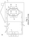
- a known prior art system illustrated in Figure 1 , that is currently available comprises at least one aluminium panel (1) and a heat pump (2).
- a refrigerant fluid, R407c, (3) is entered to the panel as a liquid at -20°C.
- the panel is outside, and absorbs heat from ambient conditions (8), including the sun during daytime, which converts the liquid into a vapour.
- This vapour then passes into the heat pump (2), where it is compressed, raising the temperature of the vapour to approximately 80°C.
- This hot vapour (hot refrigerant vapour) is entered into a heat exchanger or condenser (10, 20), where the hot refrigerant vapour imparts its heat into water (5, 5a, 5b).
- the water temperature in the tanks (10, 20) is raised to approximately 55°C.
- tank condenser 10 represents a central heating storage tank and tank condenser 20 represents a domestic hot water supply providing hot water (5b) to taps in the kitchen and bathroom of a house (7).
- the hot refrigerant vapour is directed as necessary to either the central heating tank (10) or the hot water tank (20) by means of a valve (30).
- the cooled refrigerant then passes into an expansion valve (6) before the cycle repeats.
- This system is in common usage in some southern European countries and has also been used in some northern European countries.
- JP 60233452 discloses a solar heat collector suitable for generating hot water in at least one area of a building comprising:
- thermodynamic solar system characterised in that one or both of a temperature sensor (70) and/or a humidity sensor (80) for measuring ambient temperature and/or humidity conditions of the outside environment; and wherein the control means (90) is configured for monitoring the temperature sensor (70) and/or humidity sensor (80), and wherein the control means (90) is configured to cause the fluid control valve (60) to move from the first state to a second state in whicht the flow of refrigerant, is reversed to divert hot refrigerant vapour from the heat pump (2) back into the panel (1, 1a) when the ambient conditions measured by the temperature sensor (70) and/or humidity sensor (80) are cold enough or include sufficient air moisture for frost to form on the panel.
- the heat transfer system further comprises a temperature sensor (70). This temperature sensor measures the ambient temperature conditions to which the panel is subject. The hot gas defrost cycle will only then initiate when the ambient conditions are cold enough to require it.
- the system comprises a humidity sensor (80).
- the humidity sensor measures the ambient humidity to which the panel is subject.
- the hot gas defrost cycle then only initiates when the ambient conditions to which the panel is subject include sufficient air moisture for frost or ice to form.
- This humidity sensor may operate in combination with the temperature sensor previously noted.
- the hot gas defrost cycle will only initiate when the combination of temperature and humidity are such that there is a likelihood of frost or ice forming on the panel or panels.
- a system could be automated and may comprise a computing or other control device (90) such as an Electronic Control Unit (ECU) which monitors the readings of the temperature sensor and/or humidity sensor, and regulates the time and frequency of use of the hot gas defrost cycle in response to these outputs so as to maximise the efficiency of the system, whilst still maintaining the desirable effects of the hot gas defrost cycle.
- ECU Electronic Control Unit
- the temperature sensor measures the ambient temperature conditions to which the panel is subject. The hot gas defrost cycle will only then initiate when the ambient conditions are cold enough to require it.
- the humidity sensor measures the ambient humidity to which the panel is subject.
- the hot gas defrost cycle then only initiates when the ambient conditions to which the panel is subject include sufficient air moisture for frost or ice to form.
- This humidity sensor may operate in combination with the temperature sensor previously noted.
- the hot gas defrost cycle will only initiate when the combination of temperature and humidity are such that there is a likelihood of frost or ice forming on the panel or panels.
- a system could be automated and may comprise a computing or other control device (90) such as an Electronic Control Unit (ECU) which monitors the readings of the temperature sensor and/or humidity sensor, and regulates the time and frequency of use of the hot gas defrost cycle in response to these outputs so as to maximise the efficiency of the system, whilst still maintaining the desirable effects of the hot gas defrost cycle.
- ECU Electronic Control Unit
- Existing system panels tend to be constructed of blown cold roll-bonded aluminium.
- Two flat sheets of aluminium are pressed together by mechanical rollers.
- a pattern of adhesive is laid on one of the flat sheets prior to the two sheets being laid together.
- the two sheets adhere together in accordance with the pattern - high pressure air is then forced between the sheets, and where the sheets are not bonded together, a channel is formed.
- the channels will form a track or tracks through which, as in the prior art and present example, refrigerant can flow.
- the walls (13) of the refrigerant channels of the prior art panels (1) have a typical thickness (14) of 0.7mm.
- the wall thickness has to be more typically in the region of 0.9mm. This is because the hot refrigerant vapour is at a greater pressure than the refrigerant fluid liquid or vapour passing through the panel when the system is running 'normally'.
- the increased wall thickness is necessary to contain the increased pressure.
- the refrigerant is an alternative refrigerant R-134a.
- R-134a refrigerant
- This has various advantages described later herein, but also requires a panel capable of handling a higher pressure than in a system running on R407c.
- a prior art system runs with a nominal pressure of up to approximately 12 bar maximum in a panel (1).
- refrigerant R-134a enables the system to produce hot refrigerant vapour at a higher temperature than would be obtainable with R407c.
- the hot refrigerant vapour can be at a temperature of up to (90°C) as opposed to the approximately 80°C of R407c as used in the prior art system.
- the existing prior art system where it is intended to produce a hot water supply as well as hot water for heating, requires two water tank / condenser units; one for heating the hot water (20), and one for heating the water for the heating system (10).
- tank 10 is a central heating 'buffer' tank
- tank 20 is a hot water tank.
- the hot refrigerant gas in the system is typically available to one or the other of these tanks (10,20), depending on momentary requirement, and is directed towards one or the other tank by means of a valve (30).
- water in this tank will generally be subject to a temperature gradient. Furthermore, water in this tank may be subjected to several cycles of heating and cooling before being used and exiting the tank. Given the highest temperature point of the prior art system (55°C), there is a potential issue with Legionella, as it is commonly reckoned that Legionella bacteria can survive at this temperature for anywhere between 1 to 6 hours.
- the cold water is heated as it passes through the coil and is then available as a hot water supply to taps and so on in areas such as kitchens and bathrooms.
- This system obviates the requirement for the storage of hot water in a hot water storage tank 20 and reduces the risk of Legionella.
- This improvement also means that only one tank/condenser unit (100) is required instead of two (10,20) to provide both heating water and hot water where this is required. This saves space, makes system installation easier and is likely to reduce cost.
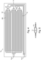
- a further improvement to the prior art system is presented in the panels (1a) in the system according to the current invention.
- These panels are specifically designed so that they may be mounted in any orientation, in contrast to prior art panels which will only work when they are fixed in a particular orientation.
- the current panels are also designed with a multiplicity of potential routes for refrigerant flow. Refrigerant entering the panel through an input/output port (11a, 11b) may split so as to follow any one of a number of routes around the panel before exiting the panel through the other input/output port (11b, 11a).
- the panel is specifically designed so that any potential route around the panel from 11a to 11b (or vice versa) is the same distance.
- An exemplary embodiment of this is shown in Figure 4 .
- the benefits of this design are that pressure distribution around the panel is more even than in a standard prior art panel, and the panel absorbs heat from its surroundings in a more efficient manner.
- a further unclaimed use of the system would be as a means of heat distribution in a desired manner in any particular building.
- a building in a warmer environment there may be a requirement to cool certain rooms in a building and provide heat to others.
- a hotel may wish to provide cooling in some rooms for the comfort of guests when the temperature is relatively high.
- the same hotel may maintain a swimming pool, which it wishes to keep at a temperature higher than even the ambient environmental temperature.
- a system in accordance with the currently noted improvements, or even a prior art system may be installed with the panel (1, 1a) in a room in which it is desired to lower the temperature.
- the system is otherwise as previously noted, with a condenser unit sited in another room and arranged so as to provide hot water to a swimming pool heating circuit. Similar arrangements may be made so as to provide central heating, underfloor heating, or even a hot water supply to other parts of the same building or even a building complex comprising a number of separate buildings. Cooling by means of the panel in one building, for example, may be provided, with the heat removed used to maintain a sauna in another building.
- the Hot Gas Defrost function in accordance with the current invention may be 0.7mm. In an exemplary embodiment of the current invention, the thickness of these walls is 0.9mm.
- FIG. 6 shows an alternative system which is not part of the invention, wherein the environment (8) in which the panel (1/la) is situated is one room (8a) within a building.
- the panel (1/la) is providing cooling for this room, which is a larder (8a).
- Tank 100 is providing hot water (5a) for a heating circuit (52) for heating a swimming pool (54), and hot water (5b) produced by the coil (40) is supplying a shower area (56).
- references to buildings, houses and/or dwellings are not intended to be limiting - it will readily be appreciated that various structures or collections of structures could have such systems installed and that the components of such systems may sit on or within a variety of locations, the reference drawings being non-limiting.
- Panels and sensors may sit on the outside of a building or on a pole or other structure next to a building.
- Various components of the system may be open to the elements or sit in wooden huts next to a building or may sit within a building.
- Buildings may include offices, hotels, restaurants or public buildings such as museums, town halls or sports centres, as well as houses or similar dwellings.
- the thickness of these walls is 0.9mm.
- FIG. 6 shows an embodiment of the improved system in accordance with the invention as previously described, wherein the environment (8) in which the panel (1/1a) is situated is one room (8a) within a building.
- the panel (1/1a) is providing cooling for this room, which is a larder (8a).
- Tank 100 is providing hot water (5a) for a heating circuit (52) for heating a swimming pool (54), and hot water (5b) produced by the coil (40) is supplying a shower area (56).
- references to buildings, houses and/or dwellings are not intended to be limiting - it will readily be appreciated that various structures or collections of structures could have such systems installed and that the components of such systems may sit on or within a variety of locations, the reference drawings being non-limiting.
- Panels and sensors may sit on the outside of a building or on a pole or other structure next to a building.
- Various components of the system may be open to the elements or sit in wooden huts next to a building or may sit within a building.
- Buildings may include offices, hotels, restaurants or public buildings such as museums, town halls or sports centres, as well as houses or similar dwellings.
Landscapes
- Engineering & Computer Science (AREA)
- General Engineering & Computer Science (AREA)
- Mechanical Engineering (AREA)
- Physics & Mathematics (AREA)
- Thermal Sciences (AREA)
- Combustion & Propulsion (AREA)
- Chemical & Material Sciences (AREA)
- Sustainable Development (AREA)
- Life Sciences & Earth Sciences (AREA)
- Sustainable Energy (AREA)
- Computer Hardware Design (AREA)
- Water Supply & Treatment (AREA)
- Building Environments (AREA)
- Heat-Pump Type And Storage Water Heaters (AREA)
- Steam Or Hot-Water Central Heating Systems (AREA)
Claims (10)
- Système solaire thermodynamique approprié pour générer de l'eau chaude (5a, 5b) dans au moins une zone d'un bâtiment (7) comprenant :au moins un panneau de transfert de chaleur (1, 1a) pour capter la chaleur d'un environnement extérieur (8), y compris le soleil, pour convertir un fluide réfrigérant de liquide en vapeur ;une pompe à chaleur (2) pour comprimer la vapeur de réfrigérant provenant du panneau en vapeur de réfrigérant chaude, et ;un condenseur (10, 20, 100) pour transférer la chaleur provenant de la vapeur de réfrigérant chaude à une alimentation en eau (5, 5c) ;un détendeur (6) à travers lequel, lors de l'utilisation, passe de la vapeur de réfrigérant refroidie provenant du condenseur avant d'être réintroduite dans le panneau (1, 1a);une vanne de régulation de fluide (60) ayant un premier état dans lequel, lors de l'utilisation, le fluide réfrigérant provenant du panneau (1, 1a) passe à travers la vanne de régulation de fluide (60) dans la pompe à chaleur (2), puis revient à travers la vanne de régulation de fluide dans le condenseur (10, 20, 100) ; etun moyen de commande (90) pour commander la vanne de régulation de fluide (60) ;caractérisé en ce que le système de transfert de chaleur comprend en outre :un capteur de température (70) et/ou un capteur d'humidité (80), pour mesurer la température ambiante et/ou les conditions d'humidité de l'environnement extérieur ; etle moyen de commande (90) étant conçu pour surveiller le capteur de température (70) et/ou le capteur d'humidité (80), etle moyen de commande (90) étant conçu pour amener la vanne de régulation de fluide (60) à passer du premier état à un second état dans lequel le flux de réfrigérant est inversé pour ramener la vapeur de réfrigérant chaud de la pompe à chaleur (2) vers le panneau (1, 1a) lorsque les conditions ambiantes mesurées par le capteur de température (70) et/ou le capteur d'humidité (80) sont suffisamment froides ou comprennent suffisamment d'humidité d'air pour que du givre ou de la glace se forme sur le panneau.
- Système de transfert de chaleur selon la revendication 1 ou 2, la vanne de régulation de fluide étant une vanne à 4 voies.
- Système de transfert de chaleur selon l'une quelconque des revendications précédentes, le réfrigérant utilisé étant le R-134a.
- Système de transfert de chaleur selon l'une quelconque des revendications précédentes, le panneau étant un panneau en aluminium collé en rouleau ayant des canaux dans lesquels le fluide réfrigérant s'écoule lorsqu'il est utilisé.
- Système de transfert de chaleur selon la revendication 4, l'épaisseur de paroi des canaux étant supérieure à 0,7 mm.
- Système de transfert de chaleur selon la revendication 4 ou 5, l'épaisseur de paroi des canaux du panneau étant supérieure à 0,9 mm.
- Système de transfert de chaleur selon l'une quelconque des revendications 4 à 6, le panneau étant conçu de sorte que le fluide réfrigérant puisse emprunter un certain nombre de chemins différents à travers les canaux dans le panneau.
- Système de transfert de chaleur selon la revendication 7, le panneau étant en outre conçu de sorte que chaque trajet possible soit sensiblement de la même longueur.
- Système de transfert de chaleur selon la revendication 1, le condenseur (10, 20, 100) pour le gaz réfrigérant chaud étant un réservoir pour un système de chauffage domestique dans lequel une alimentation en eau (5, 5a) est chauffée, lors de l'utilisation, par le gaz réfrigérant chaud et stockée, lors de l'utilisation, dans le réservoir, le réservoir comprenant en outre une bobine (40) placée vers et dans l'extrémité supérieure du réservoir dans laquelle une seconde alimentation en eau (5c-5b) est à son tour chauffée, lors de l'utilisation, par l'eau chaude stockée (5a) dans le réservoir.
- Système de transfert de chaleur selon la revendication 9, la première alimentation en eau (5-5a) étant utilisée dans un circuit de chauffage dans le bâtiment (7), la seconde alimentation en eau (5c-5b) étant utilisée comme source d'eau chaude.
Applications Claiming Priority (2)
| Application Number | Priority Date | Filing Date | Title |
|---|---|---|---|
| GB1219788.5A GB2497171B (en) | 2012-11-02 | 2012-11-02 | Improvements to thermodynamic solar heat transfer systems |
| PCT/GB2013/052859 WO2014068326A1 (fr) | 2012-11-02 | 2013-11-01 | Perfectionnements de systèmes de transfert de chaleur solaire thermodynamiques |
Publications (2)
| Publication Number | Publication Date |
|---|---|
| EP2959230A1 EP2959230A1 (fr) | 2015-12-30 |
| EP2959230B1 true EP2959230B1 (fr) | 2020-02-19 |
Family
ID=47429102
Family Applications (1)
| Application Number | Title | Priority Date | Filing Date |
|---|---|---|---|
| EP13786730.5A Active EP2959230B1 (fr) | 2012-11-02 | 2013-11-01 | Perfectionnements de systèmes de transfert de chaleur solaire thermodynamiques |
Country Status (4)
| Country | Link |
|---|---|
| US (1) | US20150276236A1 (fr) |
| EP (1) | EP2959230B1 (fr) |
| GB (1) | GB2497171B (fr) |
| WO (1) | WO2014068326A1 (fr) |
Families Citing this family (21)
| Publication number | Priority date | Publication date | Assignee | Title |
|---|---|---|---|---|
| NO335489B1 (no) * | 2013-08-27 | 2014-12-22 | Langåker John Magne | Multifunksjons varmepumpe |
| US10415903B2 (en) * | 2014-10-15 | 2019-09-17 | Hamilton Sundstrand Corporation | Prevention of cooling flow blockage |
| CN104633746B (zh) * | 2015-02-10 | 2017-07-25 | 芜湖美的厨卫电器制造有限公司 | 燃泵互补热水系统的控制方法 |
| CN105333543A (zh) * | 2015-07-03 | 2016-02-17 | 方颖 | 一种多功能中央空调系统及其运行控制方法 |
| FR3038966B1 (fr) * | 2015-07-17 | 2017-08-11 | Soc Muller Et Compagie | Chauffe-eau thermodynamique utilisant une quantite reduite de fluide frigorigene |
| JP2017166761A (ja) * | 2016-03-17 | 2017-09-21 | パナソニックIpマネジメント株式会社 | ヒートポンプ給湯機 |
| CN106765447A (zh) * | 2016-12-28 | 2017-05-31 | 佛山市恒学科技服务有限公司 | 一种耦合式热泵热水机组 |
| US11060480B2 (en) | 2017-11-14 | 2021-07-13 | The Boeing Company | Sound-attenuating heat exchangers and methods of utilizing the same |
| US10619570B2 (en) * | 2017-11-14 | 2020-04-14 | The Boeing Company | Dendritic heat exchangers and methods of utilizing the same |
| CN109990463B (zh) * | 2017-12-29 | 2022-06-17 | 青岛经济技术开发区海尔热水器有限公司 | 一种变频太阳能热泵热水器控制方法及系统 |
| CN109990479B (zh) * | 2017-12-29 | 2022-06-14 | 青岛经济技术开发区海尔热水器有限公司 | 一种变频太阳能热泵热水器控制方法及系统 |
| CN109990491B (zh) * | 2017-12-29 | 2022-06-17 | 青岛经济技术开发区海尔热水器有限公司 | 一种变频太阳能热泵热水器控制方法及系统 |
| CN109990492B (zh) * | 2017-12-29 | 2022-06-17 | 青岛经济技术开发区海尔热水器有限公司 | 一种变频太阳能热泵热水器控制方法及系统 |
| CN109028466A (zh) * | 2018-06-12 | 2018-12-18 | 重庆美的通用制冷设备有限公司 | 空调机组、蒸发器的防冻方法、装置以及系统 |
| BE1026560B1 (nl) * | 2018-08-24 | 2020-03-26 | Acb Airconditioning Bvba | Verwarmingsinrichting voor zwembadwater, zwembadinrichting en werkwijze om zwembadwater te verwarmen |
| GB2582137B (en) * | 2019-03-11 | 2023-10-04 | Icax Ltd | Heat pump system |
| US11143170B2 (en) | 2019-06-28 | 2021-10-12 | The Boeing Company | Shape memory alloy lifting tubes and shape memory alloy actuators including the same |
| US11168584B2 (en) | 2019-06-28 | 2021-11-09 | The Boeing Company | Thermal management system using shape memory alloy actuator |
| US11525438B2 (en) | 2019-06-28 | 2022-12-13 | The Boeing Company | Shape memory alloy actuators and thermal management systems including the same |
| EP4071430A1 (fr) * | 2021-04-08 | 2022-10-12 | BDR Thermea Group B.V. | Condensateur |
| GB2602584B (en) * | 2022-03-18 | 2023-01-04 | Brass Monkey Health Ltd | An ice bath |
Citations (2)
| Publication number | Priority date | Publication date | Assignee | Title |
|---|---|---|---|---|
| JPS60233452A (ja) * | 1984-05-07 | 1985-11-20 | Matsushita Electric Ind Co Ltd | 太陽熱利用集熱装置 |
| EP2375195A1 (fr) * | 2009-01-05 | 2011-10-12 | Mitsubishi Electric Corporation | Chauffe-eau du type pompe a chaleur |
Family Cites Families (15)
| Publication number | Priority date | Publication date | Assignee | Title |
|---|---|---|---|---|
| JPS60144576A (ja) * | 1984-01-06 | 1985-07-30 | ミサワホ−ム株式会社 | ヒ−トポンプ装置 |
| US4644759A (en) * | 1985-05-23 | 1987-02-24 | Thermal Concepts, Inc. | Heat pump and method |
| JPS62142945A (ja) * | 1985-12-18 | 1987-06-26 | Matsushita Seiko Co Ltd | ヒ−トポンプ式空気調和機 |
| JPS63105367A (ja) * | 1986-10-21 | 1988-05-10 | Matsushita Electric Ind Co Ltd | 太陽熱利用給湯装置 |
| US4955435A (en) * | 1987-04-08 | 1990-09-11 | Du Pont Canada, Inc. | Heat exchanger fabricated from polymer compositions |
| EP1033541B1 (fr) * | 1997-11-17 | 2004-07-21 | Daikin Industries, Limited | Appareil refrigerant |
| AU1449000A (en) * | 1998-10-20 | 2000-05-08 | John A. Broadbent | Low cost ice making evaporator |
| JP2001041478A (ja) * | 1999-08-02 | 2001-02-13 | Toshiba Electric Appliance Co Ltd | 貯湯式給湯装置 |
| FR2894501B1 (fr) * | 2005-12-14 | 2008-02-22 | Alcan Rhenalu Sa | Procede de fabrication de panneaux en aluminium a tenue a la corrosion amelioree en milieu aqueux |
| EP2103890B1 (fr) * | 2008-03-20 | 2013-09-04 | Daikin Industries, Ltd. | Dispositif de chauffage et procédé de contrôle du chauffage |
| JP2010144938A (ja) * | 2008-12-16 | 2010-07-01 | Mitsubishi Electric Corp | ヒートポンプ給湯装置およびその運転方法 |
| JP5427428B2 (ja) * | 2009-02-06 | 2014-02-26 | 三菱重工業株式会社 | ヒートポンプ式給湯・空調装置 |
| CN201547955U (zh) * | 2009-11-07 | 2010-08-11 | 广东美的电器股份有限公司 | 空气源制冷剂循环热泵热水器 |
| CN102128528B (zh) * | 2011-03-30 | 2012-07-18 | 华南理工大学 | 一种用于空气源热泵热水器的相变蓄热型除霜系统 |
| JP5884042B2 (ja) * | 2011-05-31 | 2016-03-15 | パナソニックIpマネジメント株式会社 | ヒートポンプ式温水暖房装置 |
-
2012
- 2012-11-02 GB GB1219788.5A patent/GB2497171B/en active Active
-
2013
- 2013-11-01 EP EP13786730.5A patent/EP2959230B1/fr active Active
- 2013-11-01 US US14/440,171 patent/US20150276236A1/en not_active Abandoned
- 2013-11-01 WO PCT/GB2013/052859 patent/WO2014068326A1/fr active Application Filing
Patent Citations (2)
| Publication number | Priority date | Publication date | Assignee | Title |
|---|---|---|---|---|
| JPS60233452A (ja) * | 1984-05-07 | 1985-11-20 | Matsushita Electric Ind Co Ltd | 太陽熱利用集熱装置 |
| EP2375195A1 (fr) * | 2009-01-05 | 2011-10-12 | Mitsubishi Electric Corporation | Chauffe-eau du type pompe a chaleur |
Also Published As
| Publication number | Publication date |
|---|---|
| GB201219788D0 (en) | 2012-12-19 |
| GB2497171B (en) | 2013-10-16 |
| GB2497171A (en) | 2013-06-05 |
| WO2014068326A1 (fr) | 2014-05-08 |
| EP2959230A1 (fr) | 2015-12-30 |
| US20150276236A1 (en) | 2015-10-01 |
Similar Documents
| Publication | Publication Date | Title |
|---|---|---|
| EP2959230B1 (fr) | Perfectionnements de systèmes de transfert de chaleur solaire thermodynamiques | |
| US8122944B2 (en) | Combined potable water-surface heating and cooling system | |
| Büyükalaca et al. | Experimental investigation of Seyhan River and dam lake as heat source–sink for a heat pump | |
| US9372017B2 (en) | Energy efficient cooling and heating system | |
| US20070261421A1 (en) | Packaged Chilling Systems For Building Air Conditioning And Process Cooling | |
| US11118799B2 (en) | Outside air handling unit | |
| GB2247072A (en) | Heating or cooling system | |
| US20190360703A1 (en) | Temperature management system | |
| US20090019876A1 (en) | Irrigation reservoir cooling system | |
| US20150300699A1 (en) | Heating system | |
| US9551535B2 (en) | Apparatus and method for cooling selected portions of swimming pool water | |
| JP6442712B2 (ja) | 熱利用装置 | |
| KR20100005250A (ko) | 히트펌프식 냉난방 및 냉온수 공급 시스템 | |
| JP6141970B2 (ja) | 加熱設備 | |
| Karlsson et al. | Heat pump systems in Sweden-Country report for IEA HPP Annex 28 | |
| CN108643608B (zh) | 一种采用冷热源一体化围护结构的零能耗岗亭 | |
| CN104729139B (zh) | 利用房屋建筑材料和室内空气供暖的方法及热冷空调设备 | |
| JP5016385B2 (ja) | 蓄熱装置及びこれを用いた空調装置 | |
| EP4407239A1 (fr) | Centre d'énergie géothermique modulaire | |
| CN1300527C (zh) | 四季节能环保冷暖空调三用机 | |
| CN204373295U (zh) | 带有一体式制冷系统的多库房冷库 | |
| RU2767128C1 (ru) | Устройство системы отопления пола зданий и сооружений | |
| RU2301944C1 (ru) | Способ отопления зданий | |
| US10634411B2 (en) | Energy efficient refrigerated room with optionally associated geothermal earth loop system | |
| US20160161157A1 (en) | Direct Heat Exchange System |
Legal Events
| Date | Code | Title | Description |
|---|---|---|---|
| PUAI | Public reference made under article 153(3) epc to a published international application that has entered the european phase |
Free format text: ORIGINAL CODE: 0009012 |
|
| 17P | Request for examination filed |
Effective date: 20151103 |
|
| AK | Designated contracting states |
Kind code of ref document: A1 Designated state(s): AL AT BE BG CH CY CZ DE DK EE ES FI FR GB GR HR HU IE IS IT LI LT LU LV MC MK MT NL NO PL PT RO RS SE SI SK SM TR |
|
| AX | Request for extension of the european patent |
Extension state: BA ME |
|
| DAX | Request for extension of the european patent (deleted) | ||
| 17Q | First examination report despatched |
Effective date: 20160901 |
|
| STAA | Information on the status of an ep patent application or granted ep patent |
Free format text: STATUS: EXAMINATION IS IN PROGRESS |
|
| REG | Reference to a national code |
Ref country code: DE Ref legal event code: R079 Ref document number: 602013066149 Country of ref document: DE Free format text: PREVIOUS MAIN CLASS: F24D0019000000 Ipc: F24H0001500000 |
|
| GRAP | Despatch of communication of intention to grant a patent |
Free format text: ORIGINAL CODE: EPIDOSNIGR1 |
|
| STAA | Information on the status of an ep patent application or granted ep patent |
Free format text: STATUS: GRANT OF PATENT IS INTENDED |
|
| RIC1 | Information provided on ipc code assigned before grant |
Ipc: F24D 3/18 20060101ALI20181116BHEP Ipc: F24H 4/04 20060101ALI20181116BHEP Ipc: F24D 17/00 20060101ALI20181116BHEP Ipc: F24D 11/02 20060101ALI20181116BHEP Ipc: F28F 3/14 20060101ALI20181116BHEP Ipc: F24F 110/22 20180101ALI20181116BHEP Ipc: F24F 5/00 20060101ALI20181116BHEP Ipc: F24D 19/00 20060101ALI20181116BHEP Ipc: F28D 21/00 20060101ALI20181116BHEP Ipc: F24F 110/12 20180101ALI20181116BHEP Ipc: F24D 19/10 20060101ALI20181116BHEP Ipc: F25B 47/02 20060101ALI20181116BHEP Ipc: F24D 3/08 20060101ALI20181116BHEP Ipc: F24F 11/42 20180101ALI20181116BHEP Ipc: F24H 1/50 20060101AFI20181116BHEP Ipc: F25B 30/02 20060101ALI20181116BHEP |
|
| INTG | Intention to grant announced |
Effective date: 20181211 |
|
| RIC1 | Information provided on ipc code assigned before grant |
Ipc: F24D 11/02 20060101ALI20181116BHEP Ipc: F24F 110/12 20180101ALI20181116BHEP Ipc: F24D 19/10 20060101ALI20181116BHEP Ipc: F28D 21/00 20060101ALI20181116BHEP Ipc: F24D 3/08 20060101ALI20181116BHEP Ipc: F28F 3/14 20060101ALI20181116BHEP Ipc: F25B 30/02 20060101ALI20181116BHEP Ipc: F25B 47/02 20060101ALI20181116BHEP Ipc: F24H 4/04 20060101ALI20181116BHEP Ipc: F24F 110/22 20180101ALI20181116BHEP Ipc: F24D 17/00 20060101ALI20181116BHEP Ipc: F24D 3/18 20060101ALI20181116BHEP Ipc: F24F 5/00 20060101ALI20181116BHEP Ipc: F24D 19/00 20060101ALI20181116BHEP Ipc: F24H 1/50 20060101AFI20181116BHEP Ipc: F24F 11/42 20180101ALI20181116BHEP |
|
| GRAS | Grant fee paid |
Free format text: ORIGINAL CODE: EPIDOSNIGR3 |
|
| GRAA | (expected) grant |
Free format text: ORIGINAL CODE: 0009210 |
|
| STAA | Information on the status of an ep patent application or granted ep patent |
Free format text: STATUS: THE PATENT HAS BEEN GRANTED |
|
| AK | Designated contracting states |
Kind code of ref document: B1 Designated state(s): AL AT BE BG CH CY CZ DE DK EE ES FI FR GB GR HR HU IE IS IT LI LT LU LV MC MK MT NL NO PL PT RO RS SE SI SK SM TR |
|
| REG | Reference to a national code |
Ref country code: GB Ref legal event code: FG4D |
|
| REG | Reference to a national code |
Ref country code: CH Ref legal event code: EP |
|
| REG | Reference to a national code |
Ref country code: DE Ref legal event code: R096 Ref document number: 602013066149 Country of ref document: DE |
|
| REG | Reference to a national code |
Ref country code: AT Ref legal event code: REF Ref document number: 1235420 Country of ref document: AT Kind code of ref document: T Effective date: 20200315 |
|
| REG | Reference to a national code |
Ref country code: IE Ref legal event code: FG4D |
|
| REG | Reference to a national code |
Ref country code: NL Ref legal event code: MP Effective date: 20200219 |
|
| PG25 | Lapsed in a contracting state [announced via postgrant information from national office to epo] |
Ref country code: FI Free format text: LAPSE BECAUSE OF FAILURE TO SUBMIT A TRANSLATION OF THE DESCRIPTION OR TO PAY THE FEE WITHIN THE PRESCRIBED TIME-LIMIT Effective date: 20200219 Ref country code: RS Free format text: LAPSE BECAUSE OF FAILURE TO SUBMIT A TRANSLATION OF THE DESCRIPTION OR TO PAY THE FEE WITHIN THE PRESCRIBED TIME-LIMIT Effective date: 20200219 Ref country code: NO Free format text: LAPSE BECAUSE OF FAILURE TO SUBMIT A TRANSLATION OF THE DESCRIPTION OR TO PAY THE FEE WITHIN THE PRESCRIBED TIME-LIMIT Effective date: 20200519 |
|
| REG | Reference to a national code |
Ref country code: LT Ref legal event code: MG4D |
|
| PG25 | Lapsed in a contracting state [announced via postgrant information from national office to epo] |
Ref country code: BG Free format text: LAPSE BECAUSE OF FAILURE TO SUBMIT A TRANSLATION OF THE DESCRIPTION OR TO PAY THE FEE WITHIN THE PRESCRIBED TIME-LIMIT Effective date: 20200519 Ref country code: GR Free format text: LAPSE BECAUSE OF FAILURE TO SUBMIT A TRANSLATION OF THE DESCRIPTION OR TO PAY THE FEE WITHIN THE PRESCRIBED TIME-LIMIT Effective date: 20200520 Ref country code: HR Free format text: LAPSE BECAUSE OF FAILURE TO SUBMIT A TRANSLATION OF THE DESCRIPTION OR TO PAY THE FEE WITHIN THE PRESCRIBED TIME-LIMIT Effective date: 20200219 Ref country code: LV Free format text: LAPSE BECAUSE OF FAILURE TO SUBMIT A TRANSLATION OF THE DESCRIPTION OR TO PAY THE FEE WITHIN THE PRESCRIBED TIME-LIMIT Effective date: 20200219 Ref country code: IS Free format text: LAPSE BECAUSE OF FAILURE TO SUBMIT A TRANSLATION OF THE DESCRIPTION OR TO PAY THE FEE WITHIN THE PRESCRIBED TIME-LIMIT Effective date: 20200619 Ref country code: SE Free format text: LAPSE BECAUSE OF FAILURE TO SUBMIT A TRANSLATION OF THE DESCRIPTION OR TO PAY THE FEE WITHIN THE PRESCRIBED TIME-LIMIT Effective date: 20200219 |
|
| PG25 | Lapsed in a contracting state [announced via postgrant information from national office to epo] |
Ref country code: NL Free format text: LAPSE BECAUSE OF FAILURE TO SUBMIT A TRANSLATION OF THE DESCRIPTION OR TO PAY THE FEE WITHIN THE PRESCRIBED TIME-LIMIT Effective date: 20200219 |
|
| PG25 | Lapsed in a contracting state [announced via postgrant information from national office to epo] |
Ref country code: ES Free format text: LAPSE BECAUSE OF FAILURE TO SUBMIT A TRANSLATION OF THE DESCRIPTION OR TO PAY THE FEE WITHIN THE PRESCRIBED TIME-LIMIT Effective date: 20200219 Ref country code: CZ Free format text: LAPSE BECAUSE OF FAILURE TO SUBMIT A TRANSLATION OF THE DESCRIPTION OR TO PAY THE FEE WITHIN THE PRESCRIBED TIME-LIMIT Effective date: 20200219 Ref country code: DK Free format text: LAPSE BECAUSE OF FAILURE TO SUBMIT A TRANSLATION OF THE DESCRIPTION OR TO PAY THE FEE WITHIN THE PRESCRIBED TIME-LIMIT Effective date: 20200219 Ref country code: EE Free format text: LAPSE BECAUSE OF FAILURE TO SUBMIT A TRANSLATION OF THE DESCRIPTION OR TO PAY THE FEE WITHIN THE PRESCRIBED TIME-LIMIT Effective date: 20200219 Ref country code: SM Free format text: LAPSE BECAUSE OF FAILURE TO SUBMIT A TRANSLATION OF THE DESCRIPTION OR TO PAY THE FEE WITHIN THE PRESCRIBED TIME-LIMIT Effective date: 20200219 Ref country code: PT Free format text: LAPSE BECAUSE OF FAILURE TO SUBMIT A TRANSLATION OF THE DESCRIPTION OR TO PAY THE FEE WITHIN THE PRESCRIBED TIME-LIMIT Effective date: 20200712 Ref country code: LT Free format text: LAPSE BECAUSE OF FAILURE TO SUBMIT A TRANSLATION OF THE DESCRIPTION OR TO PAY THE FEE WITHIN THE PRESCRIBED TIME-LIMIT Effective date: 20200219 Ref country code: SK Free format text: LAPSE BECAUSE OF FAILURE TO SUBMIT A TRANSLATION OF THE DESCRIPTION OR TO PAY THE FEE WITHIN THE PRESCRIBED TIME-LIMIT Effective date: 20200219 Ref country code: RO Free format text: LAPSE BECAUSE OF FAILURE TO SUBMIT A TRANSLATION OF THE DESCRIPTION OR TO PAY THE FEE WITHIN THE PRESCRIBED TIME-LIMIT Effective date: 20200219 |
|
| REG | Reference to a national code |
Ref country code: AT Ref legal event code: MK05 Ref document number: 1235420 Country of ref document: AT Kind code of ref document: T Effective date: 20200219 |
|
| REG | Reference to a national code |
Ref country code: DE Ref legal event code: R097 Ref document number: 602013066149 Country of ref document: DE |
|
| PLBE | No opposition filed within time limit |
Free format text: ORIGINAL CODE: 0009261 |
|
| STAA | Information on the status of an ep patent application or granted ep patent |
Free format text: STATUS: NO OPPOSITION FILED WITHIN TIME LIMIT |
|
| 26N | No opposition filed |
Effective date: 20201120 |
|
| PG25 | Lapsed in a contracting state [announced via postgrant information from national office to epo] |
Ref country code: AT Free format text: LAPSE BECAUSE OF FAILURE TO SUBMIT A TRANSLATION OF THE DESCRIPTION OR TO PAY THE FEE WITHIN THE PRESCRIBED TIME-LIMIT Effective date: 20200219 Ref country code: IT Free format text: LAPSE BECAUSE OF FAILURE TO SUBMIT A TRANSLATION OF THE DESCRIPTION OR TO PAY THE FEE WITHIN THE PRESCRIBED TIME-LIMIT Effective date: 20200219 |
|
| PG25 | Lapsed in a contracting state [announced via postgrant information from national office to epo] |
Ref country code: PL Free format text: LAPSE BECAUSE OF FAILURE TO SUBMIT A TRANSLATION OF THE DESCRIPTION OR TO PAY THE FEE WITHIN THE PRESCRIBED TIME-LIMIT Effective date: 20200219 Ref country code: SI Free format text: LAPSE BECAUSE OF FAILURE TO SUBMIT A TRANSLATION OF THE DESCRIPTION OR TO PAY THE FEE WITHIN THE PRESCRIBED TIME-LIMIT Effective date: 20200219 |
|
| REG | Reference to a national code |
Ref country code: DE Ref legal event code: R119 Ref document number: 602013066149 Country of ref document: DE |
|
| PG25 | Lapsed in a contracting state [announced via postgrant information from national office to epo] |
Ref country code: MC Free format text: LAPSE BECAUSE OF FAILURE TO SUBMIT A TRANSLATION OF THE DESCRIPTION OR TO PAY THE FEE WITHIN THE PRESCRIBED TIME-LIMIT Effective date: 20200219 |
|
| REG | Reference to a national code |
Ref country code: CH Ref legal event code: PL |
|
| GBPC | Gb: european patent ceased through non-payment of renewal fee |
Effective date: 20201101 |
|
| PG25 | Lapsed in a contracting state [announced via postgrant information from national office to epo] |
Ref country code: LU Free format text: LAPSE BECAUSE OF NON-PAYMENT OF DUE FEES Effective date: 20201101 |
|
| REG | Reference to a national code |
Ref country code: BE Ref legal event code: MM Effective date: 20201130 |
|
| PG25 | Lapsed in a contracting state [announced via postgrant information from national office to epo] |
Ref country code: CH Free format text: LAPSE BECAUSE OF NON-PAYMENT OF DUE FEES Effective date: 20201130 Ref country code: LI Free format text: LAPSE BECAUSE OF NON-PAYMENT OF DUE FEES Effective date: 20201130 |
|
| PG25 | Lapsed in a contracting state [announced via postgrant information from national office to epo] |
Ref country code: FR Free format text: LAPSE BECAUSE OF NON-PAYMENT OF DUE FEES Effective date: 20201130 |
|
| PG25 | Lapsed in a contracting state [announced via postgrant information from national office to epo] |
Ref country code: GB Free format text: LAPSE BECAUSE OF NON-PAYMENT OF DUE FEES Effective date: 20201101 Ref country code: DE Free format text: LAPSE BECAUSE OF NON-PAYMENT OF DUE FEES Effective date: 20210601 |
|
| PG25 | Lapsed in a contracting state [announced via postgrant information from national office to epo] |
Ref country code: TR Free format text: LAPSE BECAUSE OF FAILURE TO SUBMIT A TRANSLATION OF THE DESCRIPTION OR TO PAY THE FEE WITHIN THE PRESCRIBED TIME-LIMIT Effective date: 20200219 Ref country code: MT Free format text: LAPSE BECAUSE OF FAILURE TO SUBMIT A TRANSLATION OF THE DESCRIPTION OR TO PAY THE FEE WITHIN THE PRESCRIBED TIME-LIMIT Effective date: 20200219 Ref country code: CY Free format text: LAPSE BECAUSE OF FAILURE TO SUBMIT A TRANSLATION OF THE DESCRIPTION OR TO PAY THE FEE WITHIN THE PRESCRIBED TIME-LIMIT Effective date: 20200219 |
|
| PG25 | Lapsed in a contracting state [announced via postgrant information from national office to epo] |
Ref country code: MK Free format text: LAPSE BECAUSE OF FAILURE TO SUBMIT A TRANSLATION OF THE DESCRIPTION OR TO PAY THE FEE WITHIN THE PRESCRIBED TIME-LIMIT Effective date: 20200219 Ref country code: AL Free format text: LAPSE BECAUSE OF FAILURE TO SUBMIT A TRANSLATION OF THE DESCRIPTION OR TO PAY THE FEE WITHIN THE PRESCRIBED TIME-LIMIT Effective date: 20200219 |
|
| PG25 | Lapsed in a contracting state [announced via postgrant information from national office to epo] |
Ref country code: BE Free format text: LAPSE BECAUSE OF NON-PAYMENT OF DUE FEES Effective date: 20201130 |
|
| PGFP | Annual fee paid to national office [announced via postgrant information from national office to epo] |
Ref country code: IE Payment date: 20231121 Year of fee payment: 11 |