EP2958505B1 - Repère réfléchissant jetable - Google Patents
Repère réfléchissant jetable Download PDFInfo
- Publication number
- EP2958505B1 EP2958505B1 EP13704962.3A EP13704962A EP2958505B1 EP 2958505 B1 EP2958505 B1 EP 2958505B1 EP 13704962 A EP13704962 A EP 13704962A EP 2958505 B1 EP2958505 B1 EP 2958505B1
- Authority
- EP
- European Patent Office
- Prior art keywords
- supporting
- openings
- optically detectable
- marker according
- marker
- Prior art date
- Legal status (The legal status is an assumption and is not a legal conclusion. Google has not performed a legal analysis and makes no representation as to the accuracy of the status listed.)
- Active
Links
- 239000003550 marker Substances 0.000 title claims description 66
- 239000004744 fabric Substances 0.000 claims description 15
- 230000003287 optical effect Effects 0.000 claims description 10
- 239000000463 material Substances 0.000 description 2
- 230000005670 electromagnetic radiation Effects 0.000 description 1
- 230000001747 exhibiting effect Effects 0.000 description 1
- 239000002184 metal Substances 0.000 description 1
- 238000000034 method Methods 0.000 description 1
- 229920003023 plastic Polymers 0.000 description 1
- 239000004033 plastic Substances 0.000 description 1
Images


Classifications
-
- A—HUMAN NECESSITIES
- A61—MEDICAL OR VETERINARY SCIENCE; HYGIENE
- A61B—DIAGNOSIS; SURGERY; IDENTIFICATION
- A61B34/00—Computer-aided surgery; Manipulators or robots specially adapted for use in surgery
- A61B34/20—Surgical navigation systems; Devices for tracking or guiding surgical instruments, e.g. for frameless stereotaxis
-
- A—HUMAN NECESSITIES
- A61—MEDICAL OR VETERINARY SCIENCE; HYGIENE
- A61B—DIAGNOSIS; SURGERY; IDENTIFICATION
- A61B90/00—Instruments, implements or accessories specially adapted for surgery or diagnosis and not covered by any of the groups A61B1/00 - A61B50/00, e.g. for luxation treatment or for protecting wound edges
- A61B90/39—Markers, e.g. radio-opaque or breast lesions markers
-
- A—HUMAN NECESSITIES
- A61—MEDICAL OR VETERINARY SCIENCE; HYGIENE
- A61B—DIAGNOSIS; SURGERY; IDENTIFICATION
- A61B17/00—Surgical instruments, devices or methods, e.g. tourniquets
- A61B2017/0023—Surgical instruments, devices or methods, e.g. tourniquets disposable
-
- A—HUMAN NECESSITIES
- A61—MEDICAL OR VETERINARY SCIENCE; HYGIENE
- A61B—DIAGNOSIS; SURGERY; IDENTIFICATION
- A61B17/00—Surgical instruments, devices or methods, e.g. tourniquets
- A61B2017/00477—Coupling
-
- A—HUMAN NECESSITIES
- A61—MEDICAL OR VETERINARY SCIENCE; HYGIENE
- A61B—DIAGNOSIS; SURGERY; IDENTIFICATION
- A61B34/00—Computer-aided surgery; Manipulators or robots specially adapted for use in surgery
- A61B34/20—Surgical navigation systems; Devices for tracking or guiding surgical instruments, e.g. for frameless stereotaxis
- A61B2034/2046—Tracking techniques
- A61B2034/2055—Optical tracking systems
-
- A—HUMAN NECESSITIES
- A61—MEDICAL OR VETERINARY SCIENCE; HYGIENE
- A61B—DIAGNOSIS; SURGERY; IDENTIFICATION
- A61B90/00—Instruments, implements or accessories specially adapted for surgery or diagnosis and not covered by any of the groups A61B1/00 - A61B50/00, e.g. for luxation treatment or for protecting wound edges
- A61B90/39—Markers, e.g. radio-opaque or breast lesions markers
- A61B2090/3937—Visible markers
-
- A—HUMAN NECESSITIES
- A61—MEDICAL OR VETERINARY SCIENCE; HYGIENE
- A61B—DIAGNOSIS; SURGERY; IDENTIFICATION
- A61B90/00—Instruments, implements or accessories specially adapted for surgery or diagnosis and not covered by any of the groups A61B1/00 - A61B50/00, e.g. for luxation treatment or for protecting wound edges
- A61B90/39—Markers, e.g. radio-opaque or breast lesions markers
- A61B2090/397—Markers, e.g. radio-opaque or breast lesions markers electromagnetic other than visible, e.g. microwave
-
- A—HUMAN NECESSITIES
- A61—MEDICAL OR VETERINARY SCIENCE; HYGIENE
- A61B—DIAGNOSIS; SURGERY; IDENTIFICATION
- A61B90/00—Instruments, implements or accessories specially adapted for surgery or diagnosis and not covered by any of the groups A61B1/00 - A61B50/00, e.g. for luxation treatment or for protecting wound edges
- A61B90/39—Markers, e.g. radio-opaque or breast lesions markers
- A61B2090/3983—Reference marker arrangements for use with image guided surgery
-
- A—HUMAN NECESSITIES
- A61—MEDICAL OR VETERINARY SCIENCE; HYGIENE
- A61B—DIAGNOSIS; SURGERY; IDENTIFICATION
- A61B90/00—Instruments, implements or accessories specially adapted for surgery or diagnosis and not covered by any of the groups A61B1/00 - A61B50/00, e.g. for luxation treatment or for protecting wound edges
- A61B90/39—Markers, e.g. radio-opaque or breast lesions markers
- A61B2090/3991—Markers, e.g. radio-opaque or breast lesions markers having specific anchoring means to fixate the marker to the tissue, e.g. hooks
Definitions
- the present invention relates to a medical tracking marker which is used when an object is to be localised or tracked by means of an optical medical tracking system.
- Such medical tracking markers are known in general, for example from DE 196 39 615 A1 , and are used in conjunction with a medical navigation system.
- the above-referenced document discloses spherical markers which are to be fixed on the patient or on medical instruments via a suitable structure or "post". The markers can be screwed onto this structure so as to be held in a predetermined position relative to each other.
- producing such spherical markers as a disposable product is cost-intensive, and it is time-consuming to attach such markers to a structure, for example by screwing the individual markers onto a respective structure.
- DE 20 2004 011 567U discloses a reflecting element for a marker used in a surgical navigation system.
- the element is punched out of a suitable material preferably in a round shape and held in a frame located at the marker.
- the frame can either be added after the positioning of the element or the element can be accommodated in a matching recess.
- the marker in accordance with the disclosure comprises a structure with at least one recess, and at least one supporting element, wherein each supporting element is configured to be accommodated within a particular recess and to support at least one optically detectable element, and wherein each recess has a first opening, which allows a supporting element to be introduced into the recess, and at least two second openings which are different from the first opening, wherein each of the at least two second openings is configured to allow the at least optically detectable element supported by the supporting element to be optically detected.
- the marker in accordance with the disclosure comprises a structure which encompasses at least one supporting element, wherein at least one optically detectable element is held in place by the structure and a supporting element, such that the optically detectable element can be "seen” by an optical medical tracking system through at least two second openings formed in the structure or "body” of the marker.
- the structure itself can comprise any means suitable for attaching the structure to an object to be tracked by a medical tracking system.
- the at least one supporting element can be inserted together with at least one optically detectable element into particular recesses of the structure such that the at least one optically detectable element is positionally fixed to the object to be tracked and, if a plurality of optically detectable elements are used, positionally fixed relative to other optically detectable elements by means of supporting elements and the structure of the marker.
- the optically detectable element is a reflective layer, in particular a layer of reflective fabric.
- tracking markers are used which comprise a light-reflective surface, such that electromagnetic radiation such as visible or infrared light directed at the markers is reflected towards a camera array of an optical medical tracking system.
- the structure and the supporting elements can be configured to retain a two-dimensional reflective layer. It is also preferred if the marker in accordance with the disclosure is configured to retain a reflective fabric layer, which is already known in conjunction with spherical tracking markers.
- the second openings have a predetermined contour, in particular a circular contour, wherein the structure and at least one of the supporting elements are specifically configured to retain at least one optically detectable element in such a way that the contour of a detectable part of the at least one optically detectable element supported by the supporting element corresponds to the contour of the second openings. It could also be said that the structure and at least one of the supporting elements allow only certain parts of an optically detectable element to be optically detected. These certain parts can be defined by the contour of the openings in the marker structure, wherein this contour has to be suitable for use in conjunction with an optical tracking system.
- the contour of at least one opening can be a circular contour, since the centre of a "circular" marker can be easily determined from various directions by an optical tracking system.
- the structure of the marker and/or at least one of the at least one supporting elements can be configured to retain an optically detectable element which extends beyond the contour of at least one of the second openings assigned to said optically detectable element.
- the supporting elements and the structure can for example "pinch" the optically detectable elements in a frictional fit and/or positive fit in a region which extends beyond the contour of at least one of the second openings.
- a plurality of the second openings of the marker in accordance with the disclosure can also be configured to allow at least one optically detectable element supported by the supporting elements to be optically detected from substantially the same direction.
- the openings are then "directed" towards essentially the same direction, such that a camera array can see several optically detectable elements through a plurality of openings of the same marker.
- a plurality of the second openings to be configured to allow at least one optically detectable element supported by the supporting element to be optically detected from different directions, in particular from opposite directions, wherein the second openings are specifically situated in respective pairs which are exactly opposite each other.
- At least one of the supporting elements extends over a plurality of the second openings, such that the same optically detectable element can be seen through a plurality of second openings. Consequently, it is possible to fill a plurality of openings with a small number of optically detectable elements, thus further reducing the effort involved in assembling the marker.
- At least one of the second openings can have a chamfered edge facing away from the recess.
- a chamfered edge can exhibit any shape which is suitable for increasing the visibility of the optically detectable element situated within the opening, such that the visibility of the optically detectable element is ensured over a wide range.
- the second openings can be machined into the marker structure so as to achieve narrow tolerances with respect to the contour of the optically detectable elements, whether or not the second opening(s) has/have a chamfered edge.
- At least one of the supporting elements may provide at least one supporting surface, in particular a flat surface, for at least one of the optically detectable elements, and in particular two supporting surfaces which face away from each other.
- a supporting element could provide a frame for one or more optically detectable elements
- the supporting elements preferably support at least one optically detectable element by way of a rigid supporting surface which contacts the optically detectable element. In this way, it is also possible to shape a non-rigid optically detectable element by means of a supporting surface having a predetermined shape.
- a supporting element having two supporting surfaces facing away from each other is preferred in connection with second openings which are formed in the marker structure and situated in pairs exactly opposite each other, so as to allow the marker to be detected from opposite directions.
- At least one of the supporting elements comprises at least one cavity which is configured to accommodate an optically detectable element, wherein said at least one of the supporting surfaces is in particular formed by at least one of the cavities. This can help to prevent damage to the optically detectable element as it is introduced together with the supporting element into the recess of the marker structure.
- the depth of at least one of the cavities can essentially correspond to the thickness of an optically detectable element situated within the cavity.
- the marker structure and the supporting element are then still able to pinch the optically detectable element after it has been introduced into the marker structure.
- the marker structure and/or at least one of the supporting elements can have a resilient configuration in order to provide a detachable positive fit and/or frictional fit between the structure and at least one of the supporting elements and/or retain an optically detectable element supported by a supporting element. Forces generated by elastically deforming the structure and/or a supporting element can be used to retain the optically detectable element and hold the supporting element within the recess of the marker structure while the marker is being used for navigation.
- the structure of the marker and/or at least one of the supporting elements can also comprise a release section which is resiliently hinged to the structure and/or supporting element(s) and configured to release the positive fit or frictional fit formed between the structure and the supporting element(s), in particular by being elastically deformed, specifically compressed or pulled apart.
- the user can for example move ends of resiliently hinged arms towards or away from each other for this purpose.
- the marker structure and the supporting elements can be separated from each other after use in order to allow one or more elements of the marker to be discarded.
- At least one of the supporting elements comprises a gripping section which protrudes from the first opening and which can also form the release section.
- the position of a plurality of the second openings with respect to each other conforms to a predetermined marker arrangement which is recognised by an optical medical tracking system.
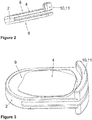
- Figure 1 shows a first embodiment of a marker in accordance with the disclosure, comprising a structure 1 and three supporting elements 2.
- the star-shaped structure 1 has a recess 3 for each supporting element 2 at the end of each of its three arms.
- Each recess 3 comprises a first opening 5, which allows a supporting element 2 to be inserted, and two circular second openings 6 which are situated exactly opposite each other.
- the user places a reflective fabric layer 4 onto the two mutually opposite supporting surfaces 8 of the supporting element 2. Only one supporting surface 8 can be seen in Figure 1 , while the second surface 8, which is flat, is situated on the lower side of the supporting element 2 and extends parallel to the first surface 8, which is also flat.
- the reflective layers can also be attached, for example glued, to the supporting surfaces 8, thereby providing a pre-assembled supporting element as a sterile disposable.
- each supporting element 2 can then be inserted into a particular recess 3 of the structure 1 as shown in Figure 1 , in a clockwise direction starting from the upper right corner in Figure 1 .
- each supporting element 2 comprises a gripping section 11 which allows a user to press one end of the supporting element 2 together. This reduces the thickness of the supporting element 2, such that the supporting element 2 can be introduced into a particular recess 3 of the structure 1.
- the gripping section 11 is released and the supporting element 2 is then held in the recess 3 by a frictional fit between the structure 1 and the supporting element 2.
- the resilient configuration of the supporting element 2 means that a spring force is applied, thus generating a frictional fit. This spring force also causes the reflective fabric layer 4 to be "pinched" between the structure 1 and the supporting element 2.
- Each second opening 6 is precisely machined into the re-usable structure 1 together with a chamfered edge 7 which allows the reflective fabric layers 4 a wide range of visibility within the respective second openings 6.
- the respective supporting element 2 can then be drawn out of each of the recesses 3, together with the reflective fabric layers 4. Damaged and/or contaminated reflective fabric layers 4 can be discarded together with the supporting elements 2, while the structure 1 can be sterilised for subsequent use or can also be discarded. It is also possible to provide the supporting elements as re-usables which can be sterilized.
- the contour of the reflective fabric layers 4 can be fairly coarse, i.e. uneven, as long as it extends beyond the contour of a respective second opening 6.
- the second openings 6 determine the effective contour of each reflective fabric layer 4.
- Figure 2 shows a preferred embodiment of a supporting element 2 comprising two parallel flat supporting surfaces 8 facing away from each other, to which reflective fabric layers 4 can be attached.
- the supporting element 2 has a resilient configuration comprising a hinge at a first end of the supporting element 2 (on the left-hand side in Figure 2 ) and a gripping and releasing section 10, 11 at a second end of the supporting element 2 which is configured to be pushed together via the hinged arms of the supporting element 2 which are formed by the supporting surfaces 8.
- the gripping section 11 is also the releasing section 10 which is configured to release the frictional fit which holds the supporting element 2 in place within a particular recess 3 of the structure 1.
- Figure 3 shows a second embodiment which differs from the embodiment shown in Figure 2 primarily in that a cavity 9 is formed on the upper surface 8 of the supporting element 2.
- a second cavity 9 (not visible in Figure 3 ) is formed on the lower surface 8.
- the cavity 9 accommodates a reflective fabric layer 4 which is therefore secure against being damaged when the supporting element 2 is introduced into a recess 3 of the structure 1.
- Figures 4 and 5 show a second embodiment of a supporting element 2, in which the releasing section 10 is different from the gripping section 11, the releasing section 10 and the gripping section 11 being situated at opposite ends of the supporting element 2.
- the gripping section 11 protrudes from the recess 3, such that a user is able to grip the gripping section 11 from without.
- the releasing section 10 protrudes from separate openings and forms a snap-fit to hold the supporting element 2 in place.
- the shape of the releasing section however hinders but does not block movement of the supporting element 2 completely so as to allow for removing the supporting element 2 from the marker structure 1.
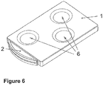
- Figure 6 shows a second embodiment of the marker structure 1 in accordance with the disclosure, in which several openings 6 are formed on the same side of the structure 1, thereby allowing the reflective fabric layer 4 within them to be detected from the same direction. It is also possible for the structure 1 shown in Figure 6 to additionally comprise corresponding openings 6 on its lower side, as already shown in the foregoing embodiments of the present disclosure.
- the supporting element 2 is configured to extend across all the openings 6 formed on one side of the structure 1, wherein a separate reflective fabric layer 4 can be provided for each opening 6 or one or more reflective fabric layers 4 can be provided for a plurality of openings 6.
Landscapes
- Health & Medical Sciences (AREA)
- Surgery (AREA)
- Life Sciences & Earth Sciences (AREA)
- Engineering & Computer Science (AREA)
- Molecular Biology (AREA)
- Animal Behavior & Ethology (AREA)
- Veterinary Medicine (AREA)
- Biomedical Technology (AREA)
- Heart & Thoracic Surgery (AREA)
- Medical Informatics (AREA)
- Nuclear Medicine, Radiotherapy & Molecular Imaging (AREA)
- Public Health (AREA)
- General Health & Medical Sciences (AREA)
- Pathology (AREA)
- Oral & Maxillofacial Surgery (AREA)
- Robotics (AREA)
- Accommodation For Nursing Or Treatment Tables (AREA)
- Endoscopes (AREA)
- Investigating Or Analysing Materials By Optical Means (AREA)
- Prostheses (AREA)
Claims (15)
- Repère destiné à une navigation médicale optique, comprenant une structure (1) avec au moins un évidement (3) et au moins un élément de support (2), dans lequel chaque élément de support (2) est conçu pour être logé dans un évidement particulier (3) et qui supporte au moins un élément optiquement détectable (4), et dans lequel chaque évidement (3) présente une première ouverture (5) qui permet à l'au moins un élément de support (2) d'être introduit dans l'évidement (3), l'au moins un évidement (3) présentant au moins deux deuxièmes ouvertures (6) qui sont différentes de la première ouverture (5), chacune des au moins deux deuxièmes ouvertures (6) étant conçue pour permettre à l'au moins un élément optiquement détectable (4) supporté par l'élément de support (2) d'être optiquement détecté par le biais d'au moins deux deuxièmes ouvertures (6) présentant un contour prédéterminé, et la structure (1) et au moins un des éléments de support (2) étant conçus spécifiquement pour retenir l'au moins un élément optiquement détectable (4) de manière à ce que le contour des parties détectables de l'au moins un élément optiquement détectable (4) supporté par l'élément de support (2) corresponde au contour des deuxièmes ouvertures (6).
- Repère selon la revendication 1, dans lequel l'élément optiquement détectable (4) est une couche réfléchissante, en particulier une couche en tissu réfléchissant.
- Repère selon l'une quelconque des revendications 1 ou 2, dans lequel les deuxièmes ouvertures (6) présentent un contour circulaire.
- Repère selon la revendication 3, dans lequel la structure (1) et/ou au moins un des au moins un élément de support (2) est/sont conçu(s) pour retenir un élément optiquement détectable (4) qui s'étend au-delà du contour d'au moins une des deuxièmes ouvertures (6) affectée audit élément optiquement détectable (4).
- Repère selon l'une quelconque des revendications 1 à 4, dans lequel une pluralité des deuxièmes ouvertures (6) sont conçues pour permettre à au moins un élément optiquement détectable (4) supporté par le(s) élément(s) de support (2) d'être optiquement détecté depuis sensiblement la même direction.
- Repère selon l'une quelconque des revendications 1 à 5, dans lequel une pluralité des deuxièmes ouvertures (6) sont conçues pour permettre à au moins un élément optiquement détectable (4) supporté par le(s) élément(s) de support (2) d'être optiquement détecté depuis des directions différentes, en particulier depuis des directions opposées, les deuxièmes ouvertures (6) étant spécifiquement situées dans des paires respectives qui sont exactement en face les unes des autres.
- Repère selon l'une quelconque des revendications 5 ou 6, dans lequel au moins un des éléments de support (2) s'étend au-dessus d'une pluralité des deuxièmes ouvertures (6).
- Repère selon l'une quelconque des revendications 1 à 7, dans lequel au moins une des deuxièmes ouvertures (6) présente un bord chanfreiné (7) opposé à l'évidement (3).
- Repère selon l'une quelconque des revendications 1 à 8, dans lequel au moins un des éléments de support (2) fournit au moins une surface de support (8), en particulier une surface plate (8), pour au moins un des éléments optiquement détectables (4), et en particulier deux surfaces de support (8) opposée l'une à l'autre.
- Repère selon l'une quelconque des revendications 1 à 9, dans lequel au moins un des éléments de support (2) comprend au moins une cavité (9) qui est conçue pour loger un élément optiquement détectable (4), ladite au moins une des surfaces de support (8) étant en particulier formée par au moins une des cavités (9).
- Repère selon la revendication 10, dans lequel la profondeur d'au moins une des cavités (9) correspond essentiellement à l'épaisseur d'un élément optiquement détectable (4).
- Repère selon l'une quelconque des revendications 1 à 11, dans lequel la structure (1) et/ou au moins un des éléments de support (2) présente(nt) une configuration souple afin de fournir une liaison de forme détachable et/ou un ajustement par frottement entre la structure (1) et au moins un des éléments de support (2) et/ou de retenir un élément optiquement détectable (4) supporté par un élément de support (2).
- Repère selon l'une quelconque des revendications 1 à 12, dans lequel la structure (1) et/ou au moins un des éléments de support (2) comprend une section de libération (10) qui est articulée de manière élastique à la structure (1) et/ou un élément de support (2) et conçue pour libérer la liaison de forme et/ou l'ajustement par frottement formés entre la structure (1) et l'élément de support (2), en particulier en comprimant ou en écartant la section de libération (10).
- Repère selon l'une quelconque des revendications 1 à 13, dans lequel au moins un des éléments de support (2) comprend une section de préhension (11) qui fait saillie depuis la première ouverture (3) et en particulier forme également la section de libération (10).
- Repère selon l'une quelconque des revendications 1 à 14, dans lequel la position d'une pluralité des deuxièmes ouvertures (6) les unes par rapport aux autres est conforme à un agencement de repère prédéterminé qui est reconnu par un système de suivi médical optique.
Applications Claiming Priority (1)
| Application Number | Priority Date | Filing Date | Title |
|---|---|---|---|
| PCT/EP2013/053349 WO2014127814A1 (fr) | 2013-02-20 | 2013-02-20 | Repère réfléchissant jetable |
Publications (2)
| Publication Number | Publication Date |
|---|---|
| EP2958505A1 EP2958505A1 (fr) | 2015-12-30 |
| EP2958505B1 true EP2958505B1 (fr) | 2017-09-06 |
Family
ID=47739271
Family Applications (1)
| Application Number | Title | Priority Date | Filing Date |
|---|---|---|---|
| EP13704962.3A Active EP2958505B1 (fr) | 2013-02-20 | 2013-02-20 | Repère réfléchissant jetable |
Country Status (3)
| Country | Link |
|---|---|
| US (1) | US10335239B2 (fr) |
| EP (1) | EP2958505B1 (fr) |
| WO (1) | WO2014127814A1 (fr) |
Families Citing this family (16)
| Publication number | Priority date | Publication date | Assignee | Title |
|---|---|---|---|---|
| US20150235076A1 (en) * | 2014-02-20 | 2015-08-20 | AiScreen Oy | Method for shooting video of playing field and filtering tracking information from the video of playing field |
| GB2536650A (en) | 2015-03-24 | 2016-09-28 | Augmedics Ltd | Method and system for combining video-based and optic-based augmented reality in a near eye display |
| USD823470S1 (en) | 2015-07-10 | 2018-07-17 | Brainlab Ag | Reference array |
| US20170086941A1 (en) | 2015-09-25 | 2017-03-30 | Atracsys | Marker for Optical Tracking System |
| EP3787543A4 (fr) | 2018-05-02 | 2022-01-19 | Augmedics Ltd. | Enregistrement d'un marqueur fiduciel pour un système de réalité augmentée |
| US11766296B2 (en) | 2018-11-26 | 2023-09-26 | Augmedics Ltd. | Tracking system for image-guided surgery |
| US10939977B2 (en) | 2018-11-26 | 2021-03-09 | Augmedics Ltd. | Positioning marker |
| USD938586S1 (en) * | 2019-06-26 | 2021-12-14 | Brainlab Ag | Medical instrument |
| US11980506B2 (en) | 2019-07-29 | 2024-05-14 | Augmedics Ltd. | Fiducial marker |
| EP3811888A1 (fr) * | 2019-10-22 | 2021-04-28 | DePuy Ireland Unlimited Company | Procédé de démontage d'un réseau de marqueurs à partir d'une fixation de réseau et assemblage de réseau pour effectuer ledit procédé |
| WO2021084484A2 (fr) * | 2019-10-29 | 2021-05-06 | Stryker European Operations Limited | Suiveur, système et procédé de navigation chirurgicale |
| US11382712B2 (en) | 2019-12-22 | 2022-07-12 | Augmedics Ltd. | Mirroring in image guided surgery |
| CN110897732A (zh) * | 2019-12-27 | 2020-03-24 | 武汉联影智融医疗科技有限公司 | 一种标定装置和手术器械标定方法 |
| US11389252B2 (en) | 2020-06-15 | 2022-07-19 | Augmedics Ltd. | Rotating marker for image guided surgery |
| US11896445B2 (en) | 2021-07-07 | 2024-02-13 | Augmedics Ltd. | Iliac pin and adapter |
| CN114404040A (zh) * | 2021-12-22 | 2022-04-29 | 苏州微创畅行机器人有限公司 | 安装构件、标记构件以及光学跟踪组件和装置 |
Family Cites Families (7)
| Publication number | Priority date | Publication date | Assignee | Title |
|---|---|---|---|---|
| DE19639615C5 (de) | 1996-09-26 | 2008-11-06 | Brainlab Ag | Reflektorenreferenzierungssystem für chirurgische und medizinische Instrumente |
| US7993353B2 (en) * | 2002-06-04 | 2011-08-09 | Brainlab Ag | Medical tracking system with universal interface |
| US7787934B2 (en) * | 2002-07-29 | 2010-08-31 | Medtronic, Inc. | Fiducial marker devices, tools, and methods |
| DE202004011567U1 (de) * | 2004-07-23 | 2004-11-18 | Aesculap Ag & Co. Kg | Reflektorelement für einen Marker eines chirurgischen Navigationssystems |
| US8442621B2 (en) | 2006-05-17 | 2013-05-14 | Nuvasive, Inc. | Surgical trajectory monitoring system and related methods |
| DE102007055456B4 (de) * | 2007-11-09 | 2010-04-22 | Aesculap Ag | Chirurgische Referenzierungseinheit und chirurgisches Navigationssystem |
| US8571637B2 (en) * | 2008-01-21 | 2013-10-29 | Biomet Manufacturing, Llc | Patella tracking method and apparatus for use in surgical navigation |
-
2013
- 2013-02-20 US US14/760,747 patent/US10335239B2/en active Active
- 2013-02-20 WO PCT/EP2013/053349 patent/WO2014127814A1/fr active Application Filing
- 2013-02-20 EP EP13704962.3A patent/EP2958505B1/fr active Active
Non-Patent Citations (1)
| Title |
|---|
| None * |
Also Published As
| Publication number | Publication date |
|---|---|
| EP2958505A1 (fr) | 2015-12-30 |
| US20150351863A1 (en) | 2015-12-10 |
| WO2014127814A1 (fr) | 2014-08-28 |
| US10335239B2 (en) | 2019-07-02 |
Similar Documents
| Publication | Publication Date | Title |
|---|---|---|
| EP2958505B1 (fr) | Repère réfléchissant jetable | |
| USD875963S1 (en) | Diagnostic instrument for medical or laboratory purposes | |
| US9827052B2 (en) | Two-part tracking reference structure | |
| USD629108S1 (en) | Spinal implant | |
| USD630329S1 (en) | Orthopedic bone block assembly | |
| USD567325S1 (en) | Optical sight reticle | |
| USD567324S1 (en) | Optical sight reticle | |
| USD567326S1 (en) | Optical sight reticle | |
| IL294211A (en) | Place marker | |
| EP1791070A3 (fr) | Systèmes destinés à faciliter les procédures chirurgicales | |
| USD851273S1 (en) | Housing with integrated test strip | |
| USD645489S1 (en) | Gonioscopic system including an optical element attachment | |
| USD645490S1 (en) | Gonioscopic system including an optical element attachment | |
| USD583053S1 (en) | Orthopedic bone block | |
| JP2007536969A5 (fr) | ||
| WO2013001377A3 (fr) | Irm du sein en décubitus dorsal | |
| USD616550S1 (en) | Blood pressure monitor | |
| USD558337S1 (en) | Anchor for holding an implantable medical lead or catheter | |
| EP3102138B1 (fr) | Ensemble de référence de suivi détachable | |
| USD654140S1 (en) | Insect repellant | |
| USD626590S1 (en) | Instrument barrel | |
| USD658682S1 (en) | Element for positioning a resonant set of a compressor | |
| EP2065304A3 (fr) | Système de capteur linéaire de véhicule | |
| WO2022094701A1 (fr) | Marqueurs optiquement détectables pour le suivi, et procédés de fabrication, d'assemblage et d'utilisation de ceux-ci | |
| CN109661540B (zh) | 具有由在印刷电路板中预先切割的舌部定向的led的医疗照明装置 |
Legal Events
| Date | Code | Title | Description |
|---|---|---|---|
| PUAI | Public reference made under article 153(3) epc to a published international application that has entered the european phase |
Free format text: ORIGINAL CODE: 0009012 |
|
| 17P | Request for examination filed |
Effective date: 20150820 |
|
| AK | Designated contracting states |
Kind code of ref document: A1 Designated state(s): AL AT BE BG CH CY CZ DE DK EE ES FI FR GB GR HR HU IE IS IT LI LT LU LV MC MK MT NL NO PL PT RO RS SE SI SK SM TR |
|
| AX | Request for extension of the european patent |
Extension state: BA ME |
|
| RIN1 | Information on inventor provided before grant (corrected) |
Inventor name: PLASSKY, NORMAN Inventor name: HUBER, HANSJOERG |
|
| DAX | Request for extension of the european patent (deleted) | ||
| RAP1 | Party data changed (applicant data changed or rights of an application transferred) |
Owner name: BRAINLAB AG |
|
| REG | Reference to a national code |
Ref country code: DE Ref legal event code: R079 Ref document number: 602013026099 Country of ref document: DE Free format text: PREVIOUS MAIN CLASS: A61B0019000000 Ipc: A61B0090000000 |
|
| RIC1 | Information provided on ipc code assigned before grant |
Ipc: A61B 17/00 20060101ALN20170328BHEP Ipc: A61B 90/00 20160101AFI20170328BHEP Ipc: A61B 34/20 20160101ALI20170328BHEP |
|
| GRAP | Despatch of communication of intention to grant a patent |
Free format text: ORIGINAL CODE: EPIDOSNIGR1 |
|
| INTG | Intention to grant announced |
Effective date: 20170509 |
|
| GRAS | Grant fee paid |
Free format text: ORIGINAL CODE: EPIDOSNIGR3 |
|
| GRAA | (expected) grant |
Free format text: ORIGINAL CODE: 0009210 |
|
| AK | Designated contracting states |
Kind code of ref document: B1 Designated state(s): AL AT BE BG CH CY CZ DE DK EE ES FI FR GB GR HR HU IE IS IT LI LT LU LV MC MK MT NL NO PL PT RO RS SE SI SK SM TR |
|
| REG | Reference to a national code |
Ref country code: GB Ref legal event code: FG4D |
|
| REG | Reference to a national code |
Ref country code: CH Ref legal event code: EP Ref country code: AT Ref legal event code: REF Ref document number: 925027 Country of ref document: AT Kind code of ref document: T Effective date: 20170915 |
|
| REG | Reference to a national code |
Ref country code: IE Ref legal event code: FG4D |
|
| REG | Reference to a national code |
Ref country code: DE Ref legal event code: R096 Ref document number: 602013026099 Country of ref document: DE |
|
| REG | Reference to a national code |
Ref country code: CH Ref legal event code: NV Representative=s name: RIEDERER HASLER AND PARTNER PATENTANWAELTE AG, CH |
|
| REG | Reference to a national code |
Ref country code: NL Ref legal event code: MP Effective date: 20170906 |
|
| REG | Reference to a national code |
Ref country code: LT Ref legal event code: MG4D |
|
| PG25 | Lapsed in a contracting state [announced via postgrant information from national office to epo] |
Ref country code: NO Free format text: LAPSE BECAUSE OF FAILURE TO SUBMIT A TRANSLATION OF THE DESCRIPTION OR TO PAY THE FEE WITHIN THE PRESCRIBED TIME-LIMIT Effective date: 20171206 Ref country code: SE Free format text: LAPSE BECAUSE OF FAILURE TO SUBMIT A TRANSLATION OF THE DESCRIPTION OR TO PAY THE FEE WITHIN THE PRESCRIBED TIME-LIMIT Effective date: 20170906 Ref country code: HR Free format text: LAPSE BECAUSE OF FAILURE TO SUBMIT A TRANSLATION OF THE DESCRIPTION OR TO PAY THE FEE WITHIN THE PRESCRIBED TIME-LIMIT Effective date: 20170906 Ref country code: FI Free format text: LAPSE BECAUSE OF FAILURE TO SUBMIT A TRANSLATION OF THE DESCRIPTION OR TO PAY THE FEE WITHIN THE PRESCRIBED TIME-LIMIT Effective date: 20170906 Ref country code: LT Free format text: LAPSE BECAUSE OF FAILURE TO SUBMIT A TRANSLATION OF THE DESCRIPTION OR TO PAY THE FEE WITHIN THE PRESCRIBED TIME-LIMIT Effective date: 20170906 |
|
| REG | Reference to a national code |
Ref country code: AT Ref legal event code: MK05 Ref document number: 925027 Country of ref document: AT Kind code of ref document: T Effective date: 20170906 |
|
| REG | Reference to a national code |
Ref country code: FR Ref legal event code: PLFP Year of fee payment: 6 |
|
| PG25 | Lapsed in a contracting state [announced via postgrant information from national office to epo] |
Ref country code: BG Free format text: LAPSE BECAUSE OF FAILURE TO SUBMIT A TRANSLATION OF THE DESCRIPTION OR TO PAY THE FEE WITHIN THE PRESCRIBED TIME-LIMIT Effective date: 20171206 Ref country code: LV Free format text: LAPSE BECAUSE OF FAILURE TO SUBMIT A TRANSLATION OF THE DESCRIPTION OR TO PAY THE FEE WITHIN THE PRESCRIBED TIME-LIMIT Effective date: 20170906 Ref country code: RS Free format text: LAPSE BECAUSE OF FAILURE TO SUBMIT A TRANSLATION OF THE DESCRIPTION OR TO PAY THE FEE WITHIN THE PRESCRIBED TIME-LIMIT Effective date: 20170906 Ref country code: GR Free format text: LAPSE BECAUSE OF FAILURE TO SUBMIT A TRANSLATION OF THE DESCRIPTION OR TO PAY THE FEE WITHIN THE PRESCRIBED TIME-LIMIT Effective date: 20171207 Ref country code: ES Free format text: LAPSE BECAUSE OF FAILURE TO SUBMIT A TRANSLATION OF THE DESCRIPTION OR TO PAY THE FEE WITHIN THE PRESCRIBED TIME-LIMIT Effective date: 20170906 |
|
| PG25 | Lapsed in a contracting state [announced via postgrant information from national office to epo] |
Ref country code: NL Free format text: LAPSE BECAUSE OF FAILURE TO SUBMIT A TRANSLATION OF THE DESCRIPTION OR TO PAY THE FEE WITHIN THE PRESCRIBED TIME-LIMIT Effective date: 20170906 |
|
| PG25 | Lapsed in a contracting state [announced via postgrant information from national office to epo] |
Ref country code: RO Free format text: LAPSE BECAUSE OF FAILURE TO SUBMIT A TRANSLATION OF THE DESCRIPTION OR TO PAY THE FEE WITHIN THE PRESCRIBED TIME-LIMIT Effective date: 20170906 Ref country code: PL Free format text: LAPSE BECAUSE OF FAILURE TO SUBMIT A TRANSLATION OF THE DESCRIPTION OR TO PAY THE FEE WITHIN THE PRESCRIBED TIME-LIMIT Effective date: 20170906 Ref country code: CZ Free format text: LAPSE BECAUSE OF FAILURE TO SUBMIT A TRANSLATION OF THE DESCRIPTION OR TO PAY THE FEE WITHIN THE PRESCRIBED TIME-LIMIT Effective date: 20170906 |
|
| PG25 | Lapsed in a contracting state [announced via postgrant information from national office to epo] |
Ref country code: SM Free format text: LAPSE BECAUSE OF FAILURE TO SUBMIT A TRANSLATION OF THE DESCRIPTION OR TO PAY THE FEE WITHIN THE PRESCRIBED TIME-LIMIT Effective date: 20170906 Ref country code: SK Free format text: LAPSE BECAUSE OF FAILURE TO SUBMIT A TRANSLATION OF THE DESCRIPTION OR TO PAY THE FEE WITHIN THE PRESCRIBED TIME-LIMIT Effective date: 20170906 Ref country code: IT Free format text: LAPSE BECAUSE OF FAILURE TO SUBMIT A TRANSLATION OF THE DESCRIPTION OR TO PAY THE FEE WITHIN THE PRESCRIBED TIME-LIMIT Effective date: 20170906 Ref country code: IS Free format text: LAPSE BECAUSE OF FAILURE TO SUBMIT A TRANSLATION OF THE DESCRIPTION OR TO PAY THE FEE WITHIN THE PRESCRIBED TIME-LIMIT Effective date: 20180106 Ref country code: EE Free format text: LAPSE BECAUSE OF FAILURE TO SUBMIT A TRANSLATION OF THE DESCRIPTION OR TO PAY THE FEE WITHIN THE PRESCRIBED TIME-LIMIT Effective date: 20170906 Ref country code: AT Free format text: LAPSE BECAUSE OF FAILURE TO SUBMIT A TRANSLATION OF THE DESCRIPTION OR TO PAY THE FEE WITHIN THE PRESCRIBED TIME-LIMIT Effective date: 20170906 |
|
| REG | Reference to a national code |
Ref country code: DE Ref legal event code: R097 Ref document number: 602013026099 Country of ref document: DE |
|
| PLBE | No opposition filed within time limit |
Free format text: ORIGINAL CODE: 0009261 |
|
| STAA | Information on the status of an ep patent application or granted ep patent |
Free format text: STATUS: NO OPPOSITION FILED WITHIN TIME LIMIT |
|
| PG25 | Lapsed in a contracting state [announced via postgrant information from national office to epo] |
Ref country code: DK Free format text: LAPSE BECAUSE OF FAILURE TO SUBMIT A TRANSLATION OF THE DESCRIPTION OR TO PAY THE FEE WITHIN THE PRESCRIBED TIME-LIMIT Effective date: 20170906 |
|
| 26N | No opposition filed |
Effective date: 20180607 |
|
| PG25 | Lapsed in a contracting state [announced via postgrant information from national office to epo] |
Ref country code: SI Free format text: LAPSE BECAUSE OF FAILURE TO SUBMIT A TRANSLATION OF THE DESCRIPTION OR TO PAY THE FEE WITHIN THE PRESCRIBED TIME-LIMIT Effective date: 20170906 |
|
| PG25 | Lapsed in a contracting state [announced via postgrant information from national office to epo] |
Ref country code: MC Free format text: LAPSE BECAUSE OF FAILURE TO SUBMIT A TRANSLATION OF THE DESCRIPTION OR TO PAY THE FEE WITHIN THE PRESCRIBED TIME-LIMIT Effective date: 20170906 |
|
| GBPC | Gb: european patent ceased through non-payment of renewal fee |
Effective date: 20180220 |
|
| REG | Reference to a national code |
Ref country code: IE Ref legal event code: MM4A |
|
| REG | Reference to a national code |
Ref country code: BE Ref legal event code: MM Effective date: 20180228 |
|
| PG25 | Lapsed in a contracting state [announced via postgrant information from national office to epo] |
Ref country code: LU Free format text: LAPSE BECAUSE OF NON-PAYMENT OF DUE FEES Effective date: 20180220 |
|
| PG25 | Lapsed in a contracting state [announced via postgrant information from national office to epo] |
Ref country code: IE Free format text: LAPSE BECAUSE OF NON-PAYMENT OF DUE FEES Effective date: 20180220 |
|
| PG25 | Lapsed in a contracting state [announced via postgrant information from national office to epo] |
Ref country code: GB Free format text: LAPSE BECAUSE OF NON-PAYMENT OF DUE FEES Effective date: 20180220 Ref country code: BE Free format text: LAPSE BECAUSE OF NON-PAYMENT OF DUE FEES Effective date: 20180228 |
|
| PG25 | Lapsed in a contracting state [announced via postgrant information from national office to epo] |
Ref country code: MT Free format text: LAPSE BECAUSE OF NON-PAYMENT OF DUE FEES Effective date: 20180220 |
|
| PG25 | Lapsed in a contracting state [announced via postgrant information from national office to epo] |
Ref country code: TR Free format text: LAPSE BECAUSE OF FAILURE TO SUBMIT A TRANSLATION OF THE DESCRIPTION OR TO PAY THE FEE WITHIN THE PRESCRIBED TIME-LIMIT Effective date: 20170906 |
|
| PG25 | Lapsed in a contracting state [announced via postgrant information from national office to epo] |
Ref country code: PT Free format text: LAPSE BECAUSE OF FAILURE TO SUBMIT A TRANSLATION OF THE DESCRIPTION OR TO PAY THE FEE WITHIN THE PRESCRIBED TIME-LIMIT Effective date: 20170906 |
|
| PG25 | Lapsed in a contracting state [announced via postgrant information from national office to epo] |
Ref country code: MK Free format text: LAPSE BECAUSE OF NON-PAYMENT OF DUE FEES Effective date: 20170906 Ref country code: HU Free format text: LAPSE BECAUSE OF FAILURE TO SUBMIT A TRANSLATION OF THE DESCRIPTION OR TO PAY THE FEE WITHIN THE PRESCRIBED TIME-LIMIT; INVALID AB INITIO Effective date: 20130220 Ref country code: CY Free format text: LAPSE BECAUSE OF FAILURE TO SUBMIT A TRANSLATION OF THE DESCRIPTION OR TO PAY THE FEE WITHIN THE PRESCRIBED TIME-LIMIT Effective date: 20170906 |
|
| PG25 | Lapsed in a contracting state [announced via postgrant information from national office to epo] |
Ref country code: AL Free format text: LAPSE BECAUSE OF FAILURE TO SUBMIT A TRANSLATION OF THE DESCRIPTION OR TO PAY THE FEE WITHIN THE PRESCRIBED TIME-LIMIT Effective date: 20170906 |
|
| PGFP | Annual fee paid to national office [announced via postgrant information from national office to epo] |
Ref country code: FR Payment date: 20230221 Year of fee payment: 11 |
|
| P01 | Opt-out of the competence of the unified patent court (upc) registered |
Effective date: 20230510 |
|
| PGFP | Annual fee paid to national office [announced via postgrant information from national office to epo] |
Ref country code: DE Payment date: 20240219 Year of fee payment: 12 Ref country code: CH Payment date: 20240301 Year of fee payment: 12 |