EP2958477B1 - Wasserdichtes verschlusssystem - Google Patents
Wasserdichtes verschlusssystem Download PDFInfo
- Publication number
- EP2958477B1 EP2958477B1 EP14754871.3A EP14754871A EP2958477B1 EP 2958477 B1 EP2958477 B1 EP 2958477B1 EP 14754871 A EP14754871 A EP 14754871A EP 2958477 B1 EP2958477 B1 EP 2958477B1
- Authority
- EP
- European Patent Office
- Prior art keywords
- lid
- closure system
- base
- closed position
- container
- Prior art date
- Legal status (The legal status is an assumption and is not a legal conclusion. Google has not performed a legal analysis and makes no representation as to the accuracy of the status listed.)
- Active
Links
- 230000000994 depressogenic effect Effects 0.000 claims description 6
- 230000008878 coupling Effects 0.000 claims description 2
- 238000010168 coupling process Methods 0.000 claims description 2
- 238000005859 coupling reaction Methods 0.000 claims description 2
- 238000007789 sealing Methods 0.000 description 24
- XLYOFNOQVPJJNP-UHFFFAOYSA-N water Substances O XLYOFNOQVPJJNP-UHFFFAOYSA-N 0.000 description 14
- 230000002093 peripheral effect Effects 0.000 description 12
- 239000000463 material Substances 0.000 description 7
- 239000000758 substrate Substances 0.000 description 7
- 238000003860 storage Methods 0.000 description 3
- 230000008901 benefit Effects 0.000 description 2
- 238000010276 construction Methods 0.000 description 2
- 239000007788 liquid Substances 0.000 description 2
- 238000004519 manufacturing process Methods 0.000 description 2
- BYXHQQCXAJARLQ-ZLUOBGJFSA-N Ala-Ala-Ala Chemical compound C[C@H](N)C(=O)N[C@@H](C)C(=O)N[C@@H](C)C(O)=O BYXHQQCXAJARLQ-ZLUOBGJFSA-N 0.000 description 1
- 239000004743 Polypropylene Substances 0.000 description 1
- 230000004888 barrier function Effects 0.000 description 1
- 230000000295 complement effect Effects 0.000 description 1
- 238000005336 cracking Methods 0.000 description 1
- 230000000694 effects Effects 0.000 description 1
- 230000001815 facial effect Effects 0.000 description 1
- 235000013410 fast food Nutrition 0.000 description 1
- 238000002347 injection Methods 0.000 description 1
- 239000007924 injection Substances 0.000 description 1
- 238000000034 method Methods 0.000 description 1
- 238000000465 moulding Methods 0.000 description 1
- 238000004806 packaging method and process Methods 0.000 description 1
- 238000012856 packing Methods 0.000 description 1
- 229920000642 polymer Polymers 0.000 description 1
- -1 polypropylene Polymers 0.000 description 1
- 229920001155 polypropylene Polymers 0.000 description 1
- 239000012815 thermoplastic material Substances 0.000 description 1
- 238000009736 wetting Methods 0.000 description 1
Images
Classifications
-
- B—PERFORMING OPERATIONS; TRANSPORTING
- B65—CONVEYING; PACKING; STORING; HANDLING THIN OR FILAMENTARY MATERIAL
- B65D—CONTAINERS FOR STORAGE OR TRANSPORT OF ARTICLES OR MATERIALS, e.g. BAGS, BARRELS, BOTTLES, BOXES, CANS, CARTONS, CRATES, DRUMS, JARS, TANKS, HOPPERS, FORWARDING CONTAINERS; ACCESSORIES, CLOSURES, OR FITTINGS THEREFOR; PACKAGING ELEMENTS; PACKAGES
- B65D43/00—Lids or covers for rigid or semi-rigid containers
- B65D43/14—Non-removable lids or covers
- B65D43/16—Non-removable lids or covers hinged for upward or downward movement
- B65D43/163—Non-removable lids or covers hinged for upward or downward movement the container and the lid being made separately
- B65D43/169—Non-removable lids or covers hinged for upward or downward movement the container and the lid being made separately the lid, the hinge and the element connecting them to the container being made of one piece
-
- B—PERFORMING OPERATIONS; TRANSPORTING
- B65—CONVEYING; PACKING; STORING; HANDLING THIN OR FILAMENTARY MATERIAL
- B65D—CONTAINERS FOR STORAGE OR TRANSPORT OF ARTICLES OR MATERIALS, e.g. BAGS, BARRELS, BOTTLES, BOXES, CANS, CARTONS, CRATES, DRUMS, JARS, TANKS, HOPPERS, FORWARDING CONTAINERS; ACCESSORIES, CLOSURES, OR FITTINGS THEREFOR; PACKAGING ELEMENTS; PACKAGES
- B65D2543/00—Lids or covers essentially for box-like containers
- B65D2543/00009—Details of lids or covers for rigid or semi-rigid containers
- B65D2543/00018—Overall construction of the lid
- B65D2543/00064—Shape of the outer periphery
- B65D2543/00074—Shape of the outer periphery curved
- B65D2543/00101—Shape of the outer periphery curved square-like or rectangular-like
-
- B—PERFORMING OPERATIONS; TRANSPORTING
- B65—CONVEYING; PACKING; STORING; HANDLING THIN OR FILAMENTARY MATERIAL
- B65D—CONTAINERS FOR STORAGE OR TRANSPORT OF ARTICLES OR MATERIALS, e.g. BAGS, BARRELS, BOTTLES, BOXES, CANS, CARTONS, CRATES, DRUMS, JARS, TANKS, HOPPERS, FORWARDING CONTAINERS; ACCESSORIES, CLOSURES, OR FITTINGS THEREFOR; PACKAGING ELEMENTS; PACKAGES
- B65D2543/00—Lids or covers essentially for box-like containers
- B65D2543/00009—Details of lids or covers for rigid or semi-rigid containers
- B65D2543/00018—Overall construction of the lid
- B65D2543/00259—Materials used
- B65D2543/00296—Plastic
-
- B—PERFORMING OPERATIONS; TRANSPORTING
- B65—CONVEYING; PACKING; STORING; HANDLING THIN OR FILAMENTARY MATERIAL
- B65D—CONTAINERS FOR STORAGE OR TRANSPORT OF ARTICLES OR MATERIALS, e.g. BAGS, BARRELS, BOTTLES, BOXES, CANS, CARTONS, CRATES, DRUMS, JARS, TANKS, HOPPERS, FORWARDING CONTAINERS; ACCESSORIES, CLOSURES, OR FITTINGS THEREFOR; PACKAGING ELEMENTS; PACKAGES
- B65D2543/00—Lids or covers essentially for box-like containers
- B65D2543/00009—Details of lids or covers for rigid or semi-rigid containers
- B65D2543/00444—Contact between the container and the lid
- B65D2543/00481—Contact between the container and the lid on the inside or the outside of the container
- B65D2543/0049—Contact between the container and the lid on the inside or the outside of the container on the inside, or a part turned to the inside of the mouth of the container
-
- B—PERFORMING OPERATIONS; TRANSPORTING
- B65—CONVEYING; PACKING; STORING; HANDLING THIN OR FILAMENTARY MATERIAL
- B65D—CONTAINERS FOR STORAGE OR TRANSPORT OF ARTICLES OR MATERIALS, e.g. BAGS, BARRELS, BOTTLES, BOXES, CANS, CARTONS, CRATES, DRUMS, JARS, TANKS, HOPPERS, FORWARDING CONTAINERS; ACCESSORIES, CLOSURES, OR FITTINGS THEREFOR; PACKAGING ELEMENTS; PACKAGES
- B65D2543/00—Lids or covers essentially for box-like containers
- B65D2543/00009—Details of lids or covers for rigid or semi-rigid containers
- B65D2543/00444—Contact between the container and the lid
- B65D2543/00481—Contact between the container and the lid on the inside or the outside of the container
- B65D2543/00537—Contact between the container and the lid on the inside or the outside of the container on the outside, or a part turned to the outside of the mouth of the container
-
- B—PERFORMING OPERATIONS; TRANSPORTING
- B65—CONVEYING; PACKING; STORING; HANDLING THIN OR FILAMENTARY MATERIAL
- B65D—CONTAINERS FOR STORAGE OR TRANSPORT OF ARTICLES OR MATERIALS, e.g. BAGS, BARRELS, BOTTLES, BOXES, CANS, CARTONS, CRATES, DRUMS, JARS, TANKS, HOPPERS, FORWARDING CONTAINERS; ACCESSORIES, CLOSURES, OR FITTINGS THEREFOR; PACKAGING ELEMENTS; PACKAGES
- B65D2543/00—Lids or covers essentially for box-like containers
- B65D2543/00009—Details of lids or covers for rigid or semi-rigid containers
- B65D2543/00444—Contact between the container and the lid
- B65D2543/00592—Snapping means
- B65D2543/00712—Snapping means on the lid
- B65D2543/00722—Profiles
- B65D2543/0074—Massive bead
-
- B—PERFORMING OPERATIONS; TRANSPORTING
- B65—CONVEYING; PACKING; STORING; HANDLING THIN OR FILAMENTARY MATERIAL
- B65D—CONTAINERS FOR STORAGE OR TRANSPORT OF ARTICLES OR MATERIALS, e.g. BAGS, BARRELS, BOTTLES, BOXES, CANS, CARTONS, CRATES, DRUMS, JARS, TANKS, HOPPERS, FORWARDING CONTAINERS; ACCESSORIES, CLOSURES, OR FITTINGS THEREFOR; PACKAGING ELEMENTS; PACKAGES
- B65D2543/00—Lids or covers essentially for box-like containers
- B65D2543/00009—Details of lids or covers for rigid or semi-rigid containers
- B65D2543/00444—Contact between the container and the lid
- B65D2543/00592—Snapping means
- B65D2543/00712—Snapping means on the lid
- B65D2543/00787—Periphery concerned
- B65D2543/00805—Segments
-
- B—PERFORMING OPERATIONS; TRANSPORTING
- B65—CONVEYING; PACKING; STORING; HANDLING THIN OR FILAMENTARY MATERIAL
- B65D—CONTAINERS FOR STORAGE OR TRANSPORT OF ARTICLES OR MATERIALS, e.g. BAGS, BARRELS, BOTTLES, BOXES, CANS, CARTONS, CRATES, DRUMS, JARS, TANKS, HOPPERS, FORWARDING CONTAINERS; ACCESSORIES, CLOSURES, OR FITTINGS THEREFOR; PACKAGING ELEMENTS; PACKAGES
- B65D2543/00—Lids or covers essentially for box-like containers
- B65D2543/00009—Details of lids or covers for rigid or semi-rigid containers
- B65D2543/00824—Means for facilitating removing of the closure
- B65D2543/00833—Integral tabs, tongues, handles or similar
- B65D2543/00842—Integral tabs, tongues, handles or similar outside of the lid
-
- B—PERFORMING OPERATIONS; TRANSPORTING
- B65—CONVEYING; PACKING; STORING; HANDLING THIN OR FILAMENTARY MATERIAL
- B65D—CONTAINERS FOR STORAGE OR TRANSPORT OF ARTICLES OR MATERIALS, e.g. BAGS, BARRELS, BOTTLES, BOXES, CANS, CARTONS, CRATES, DRUMS, JARS, TANKS, HOPPERS, FORWARDING CONTAINERS; ACCESSORIES, CLOSURES, OR FITTINGS THEREFOR; PACKAGING ELEMENTS; PACKAGES
- B65D83/00—Containers or packages with special means for dispensing contents
- B65D83/08—Containers or packages with special means for dispensing contents for dispensing thin flat articles in succession
Definitions
- Containers suitable for dispensing wiping substrates both dry and wet, are known in the art.
- Containers typically are either flexible or rigid and include a dispensing orifice to allow the consumer convenient access to the substrate. In the containers of the prior art these openings are generally situated on the upper face of the container.
- known containers In order to prevent egress of moisture in the case of wet wiping substrates or the ingress of moisture in the case of dry wiping substrates, known containers generally comprise a lid and a sealing device.
- a problem with containers of the prior art is that the sealing device often makes it difficult for the consumer to access the wipes within the container.
- the sealing device may make it difficult for a consumer to open and close the lid or may obscure the dispensing orifice and impede dispensing.
- the sealing device may also make it difficult to dispense multiple wipes at one time. For example, the sealing device may only permit access to a single wipe, making it difficult to quickly dispense multiple wipes without damaging the wipes, damaging the container or abrading the skin against the edges of the container.
- US Patent No. 7,213,720 provides a cap assembly for storing and packaging moisture-sensitive items, however, the cap includes a lip seal member that must be aligned with an opposing skirt and must be positioned so as to apply pressure to the skirt. Further, an elastomeric liner may be positioned between the skirt and the lip to improve the water-tightness of the seal. Such a design increases the complexity of both the lid and the skirt, introduces additional materials in the form of an elastomeric liner and negatively effects dispensing by introducing additional features to the dispensing orifice.
- US 5, 203,469 discloses a tool box
- WO 00/39215 discloses a package for fast food
- US 20051258180 discloses a container/hinged lid assembly
- US 5,050,737 discloses a system for packing moist towelettes having the features of the preamble of appended claims 1 and 11. It is therefore an objective of the present invention to provide a rigid container from which a dry wiping substrate can be easily dispensed, while also providing a means for preventing the ingress of water in a simple and cost effective manner.
- the present invention provides a resealable closure system in accordance with claim 1.
- the present invention may provide a resealable closure system that may be incorporated into a container for storing and dispensing moisture sensitive product, such as a dry wiping substrate and more preferably a dry wipe useful for facial cleansing or the application of make-up.
- the closure system is not only resealable, but is also substantially watertight. That is, when the closure system is integrated with a container, the closure system substantially prohibits the ingress of water into the container through the lid when the lid is in a closed position.
- the present invention solves the problem of providing a simple, cost effective and functional watertight closure system by providing a lid having a pair of downwardly extending flanges disposed along each side edge, the flanges extending beyond the base of the closure system when the lid is in a closed position, and a front edge that extends horizontally beyond the vertical plane of the front edge of the base when the lid is closed.
- These three components which are preferably integral to the lid and made form the same material, effectively prevent the ingress of water and allow for the dry storage of wiping substrates even when the container is stored in a wet environment, such as a shower.
- the present invention provides a lid attached to a base member by a hinge.
- the lid which is preferably rectangular, although it may be any shape, comprises a pair of downwardly extending flanges and a front edge that forms an overhang. When the lid is in a closed position the flanges extend beyond the upper edge of the base member and the overhang extends beyond the front edge of the base member.
- the present invention provides a closure system comprising a base having a front edge, a rear edge and a pair of opposed side edges; a lid having a front edge, a rear edge, a pair of opposed side edges and a pair of flanges extending at least partially along each of the side edges, the flanges extending substantially vertically downward from the horizontal plane of the lid; and a hinge that operatively connects the lid to the base in a movable arrangement, wherein the front edge of the lid extends beyond the vertical plane of the front edge of the base when the lid is in a closed position.
- the present invention provides a container in accordance with claim 11.
- the present invention may provide a container comprising a cup-shaped container body having a bottom and a generally annular sidewall defining an open end; a lid having a main body having opposed front and back edges and opposed side edges, the lid sized large enough to close the open end of the container body, a pair of sealing flanges extending from a bottom surface of the main body and beyond the annular sidewall in a closed position, the lid further comprising an overhanging front edge that extends beyond the annular sidewall in a closed position; a living hinge coupling the container lid and container body into a one-piece construction, the container lid pivoting through the living hinge between an open position and the closed position.
- the present invention further provides a watertight dispenser in accordance with claim 12.
- the present disclosure may provide a watertight dispenser comprising a container body having a bottom and a generally annular sidewall defining an open end and a closure system sized to cover the open end of the container, the closure system comprising a base, a lid and a hinge, wherein the lid comprises a pair of sealing flanges that extend downward from the horizontal plane of the lid and beyond the base and an overhanging front edge that extends beyond the vertical plane of the front edge of the base when the lid is in a closed position.
- the present invention provides a watertight closure system comprising a lid, a hinge and a base member.
- the base member may either be a container having a bottom and a generally annular sidewall defining an open upper portion or may simply be an annular sidewall having open top and bottom portions that may be coupled with, or otherwise joined to, a container.
- the lid, hinge and base member form a closure system that prevents the ingress of water.
- the system may be used as a closure system for a container of dry, disposable, personal cleansing articles which may be useful for cleansing the skin or hair and/or delivering skin or hair care actives to the skin or hair.
- Such articles are used by the consumer by wetting the dry article with water.
- the closure system is integrated with a container having a bottom and a generally annular sidewall defining an open upper portion upon which the bottom surface of a lid seats when the lid is in the closed position. Further, when the lid is in a closed position, the front edge of the lid extends beyond the horizontal plane of the annular sidewall thereby defining an overhanging front edge.
- the lid also comprises a sealing flange that extends downward from the lid and beyond the vertical upper portion of the container. In this manner the lid includes elements along its periphery that prevent ingress of water into the container and allow the contents thereof to remain dry even when the container is stored in a moist environment such as a shower.
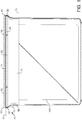
- FIG. 1 illustrates a closure system 10 according to one embodiment of the present invention.
- the closure system comprises a lid 20 and a base member 60, which are preferably joined by a hinge (not illustrated in FIG. 1 ).
- the closure system 10 may be affixed to a container 100, such as a container for storing and dispensing dry wiping products.
- other shapes and configurations of the base and lid such as round or circular, are contemplated and are intended to fall within the scope of the invention.
- the invention is not to be limited to a specific base or lid perimeter shape or overall contour.
- the lid 20 is sized to fit over the base member 60 during use. Further, the base member 60 is configured to receive the lid 20 when it is in a closed position and the lid 20 is configured to be positioned over the base member 60 in a manner that forms a seal there between and prevents the ingress of water.
- the base member 60 and the lid 20 are made of the same material. According to certain embodiments, the base member 60 and the lid 20 are formed of an injection molded suitable thermoplastic material (e.g., polymer, polypropylene, and so forth) or other material known in the art.
- suitable thermoplastic material e.g., polymer, polypropylene, and so forth
- the base member 60 and the lid 20 are a one-piece structure.
- the lid 20 is pivotally joined to the base member 60 by a hinge 40.
- the hinge 40 can be configured to mitigate cracks that might develop at or along one or more flex portions of the hinge 40 and can be constructed of a relatively thin wall that is configured to flex without breakage during an expected service life of the closure system 10.
- the hinge 40 can be formed of a material that has at least some flexibility and/or that can deform slightly or significantly in order to mitigate cracking and/or breakage of the hinge 40.
- the hinge 40 is formed with the same material as the base member 60 and the lid 20.
- the hinge is a "living hinge".
- a living hinge is a hinge formed with the base member 60 and the lid 20 as a single piece.
- a living hinge can be configured to facilitate the lid 20 being able to spring away from the base member 60 when the closure system 10 is to be opened.
- the hinge 40 provides ease of moving the lid 20.
- the hinge 40 operatively connects the lid 20 to the base member 60 in a movable arrangement, wherein the lid 20 comprises at least two positions, namely, a first position and a second position.
- the lid 20 When in the first position, the lid 20 is "open" (or moved away from the base member 60), which allows product (e.g., a specimen) to be placed into the closure system 10 (e.g., into the base member 60) and/or dispensed from the closure system 10.
- the lid 20 is in the second position, the lid 20 is closed or engaged with the base member 60, providing a secure and watertight seal according to various embodiments disclosed herein.
- the hinge 40 allows the lid 20 to be moved away from the base member 60 (e.g., flipped up, placed into first position) for dispensing and/or for filling.
- the hinge 40 can allow the lid 20 to be moved into contact with the base member 60 (e.g., placed into the body position) for storage, transport purposes, and/or for other purposes.
- the lid 20 is formed with the base member 60 as a one-piece construction and is not formed as a plurality of parts separately attached together.
- the two components are joined by a living hinge 40 that attaches the lid 20 to the base member 60.
- the living hinge 40 allows the lid 20 to pivot relative to the base member 60 between open and closed positions while permanently securing the lid 20 to the base member 60.
- the closure system may be combined with a container such that when the lid is in an open position the contents stored within the container can be accessed.
- the closure system forms a water tight seal relative to the container body in the closed position. Permanently attaching the lid 20 to the base member 60 provides the additional benefit that the lid cannot be lost or displaced from the base.
- the lid 20 is installed upright on the top of the base member 60 that has a mouth 62 that typically lies in a horizontal plane.
- the vertical direction generally corresponds to an axial direction with reference to the geometry of the closure system (comprising the body portion and the lid) and the horizontal direction or horizontal plane is perpendicular to the axial direction of the closure system (e.g., the vertical direction). It should be understood that during fabrication, molding, shipping, storage, and so forth, the base member 60 and/or lid 20 could have a non-upright orientation.
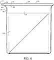
- the base member 60 annular sidewall 74 defines an open upper end. As further illustrated in FIG. 5 , the annular sidewall 74 has upper 70 and lower 72 edges. The upper edge 70 defines the upper horizontal plane 75 of the base member 60 and the lower edge of the annular sidewall 74 defines the lower horizontal plane 71 of the base.
- the base member 60 is substantially rectangular and has a pair of opposed side walls 64, 66 and opposed front and back walls 63, 65.
- the lid 20, which is generally shaped to cover the base member 60 has a main body 26 having a generally annular shaped peripheral edge that comprises front 21, rear 23 and opposing side edges 25, 27, which together form the outer peripheral edge of the lid.
- FIGS 1 and 4 extending downwardly from each side edge 25, 27, in a direction substantially perpendicular to the plane of the main body 26, are a pair of sealing flanges 30, 32.
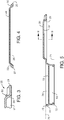
- the sealing flanges 30, 32 are illustrated in detail in FIG. 4 , which is a cross section view of a lid.
- the sealing flanges 30, 32 may be considered part of the lid 20.
- the sealing flanges 30, 32 extend axially from the main body 26 and more particularly from the bottom surface 28 of main body 26.
- the sealing flanges 30, 32 When the lid is in a closed position, the sealing flanges 30, 32 generally extend in an axially downward direction from the lid 20 beyond the horizontal plane 75 of the base. In this manner the sealing flanges 30, 32 form a seal along at least a portion of both side edges 64, 66 and prevent the ingress of water.
- the sealing flanges When the sealing flanges are employed with an overhang along the front edge of the lid, as described in more detail below, there is no need for additional seals between the base member and the lid.
- the combination of sealing flanges and overhang provide a simple and effective means of preventing water from entering the closure system.
- the flanges 30, 32 may be any suitable shape, so long as they extend substantially vertically from both edges 25, 27 of the lid 20 towards the base member 60.
- the sealing flanges are preferably wedge shaped such than they have a wider base portion proximate main body and a narrower distal tip spaced axially away from main body.
- the outer surface of the flange is radially shaped having a radius from about 0.254 mm to about 2.54 mm (about 0.01 to about 0.1 inches). In other embodiments the outer surface of the flange may be canted inwards toward the base member when the lid is in a closed position.
- the inner surface is preferably substantially perpendicular to the horizontal plane of the main body forming an angle between about 90 and about 93 degrees. When the lid is in a closed position the inner flange surface is preferably parallel to the vertical plan of the base, but is spaced away from the base member such that there is a space between the inner flange surface and the base member.
- the sealing flange may generally be any size and shape so long as it seals the edges of the closure system when the lid is in a closed position
- the flange has a tapered shape.
- the flange base has a width of between about 0.762 and 2.54 mm (about 0.03 and 0.1 inches) (measured parallel to the bottom surface of main body) and a width of between about 0.508 and 1.27 mm (about 0.02 and 0.05) inches at the distal tip.
- the height of the sealing flange is substantially constant the entire length of the sealing flange.
- the flange has a height between about 2.54 and 12.7 mm (about 0.1 and 0.5 inches) and more preferably between about 5.08 and about 7.62 mm (about 0.2 and about 0.3 inches).
- the flanges 30, 32 extend downwardly from the side edge 25, 27 towards the base member 60 when the lid 20 is in a closed position. In this manner, the flanges 30, 32 extend vertically beyond the horizontal plane 75 of the base a distance of at least about 0.05 inches, such as from about 0.05 to about 0.25 inches. In a particularly preferred embodiment, such as the embodiment illustrated in FIG. 1 , the flanges 30, 32 extend downwardly beyond the vertical plane 75 of the upper edge 70 of the base member 60 but do not contact the edge when the lid is in a closed position. In this manner there is a slight gap between the flanges 30, 32 and the base member 60, such as from about 0.01 to about 0.1 mm and more preferably from about 0.05 to about 0.075 mm, as illustrated in FIG. 1 .
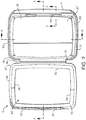
- the flanges 30, 32 extend at least partially along each side edge 25, 27. More preferably the flanges 30, 32 extend along the entire length of each side edge 25, 27. In a particularly preferred embodiment the flanges 30, 32 extend along the entire length of each side edge 25, 27 and at least partially along the rear edge 23. In a particularly preferred embodiment, such as the embodiment illustrated in FIG. 2 , the flanges 30, 32 extend along the entire length of each side edge 25, 27 and along a portion of the rear edge 23, terminating immediately adjacent to the hinge 40. In this manner, the flanges and the hinge prevent the ingress of water along the entirety of the side and rear edges.
- the front edge 21 forms an overhang 28 and therefore there is generally not a need for additional barriers to the ingress of water along the front edge 21.
- the front edge 21 does not include a flange, but rather, the flanges 30, 32 terminate immediately adjacent to the front edge 21.
- the flanges may extend at least partially around the rounded corners.
- the lid 20 includes a front edge 21 that extends beyond the front edge 63 of the base.
- the front edge 21 forms an overhang 28 that is substantially planar with the lid 20 and perpendicular to the vertical plane 77 of the base.
- the overhanging front edge 21 extends at least about 1.27 mm (about 0.05 inches) and more preferably from 2.54 mm to about 7.62 mm (0.1 to about 0.3 inches), beyond the vertical plane 77 of the base.
- the closure system comprises only one overhang, which is disposed along the front edge of the lid.
- the overhang 28 forms a drip edge to facilitate the flow of liquid off the lid 20 along its front edge 21.
- the top and bottom surfaces of the overhang 28 are generally parallel to one another and substantially parallel to the horizontal plane of the lid 20.
- the overhang is curved generally downwardly to form a drip edge to facilitate the flow of liquid off the lid.
- Other cross-sectional shapes are also possible depending on the particular application in which lid will be used.
- FIG. 5 is a cross section of FIG. 2 through line A-A, a particularly preferred embodiment of a lid 20 is illustrated.
- the lid 20 has a central recessed or sunken section 27 surrounded by a vertical upstanding lid wall 29 that faces the recessed section 27.
- the lid wall 29 has four side segments that correspond to the four-sided shape of the lid 20.
- the upper edge 70 of the base is provided with a lip 73 that extends radially outward.
- the downwardly extending wall 29 defines the peripheral edge of the central depressed portion 27 and the lip 73 defines the peripheral edge of the central open portion, or mouth 62 of the base.
- the periphery of the central depressed portion 27 is slightly greater than the periphery of mouth 62 of the body so that at least a portion of the depressed central portion 27 contacts the lip 73 when the lid 20 is in a closed position.
- the base member 60 is defined by opposing side walls 64, 66 and front 63 and back 65 walls.
- the container of the present invention may have a circular or oval shape with only a peripheral upstanding wall.
- the front 63, back 65 and side walls 64, 66 of the base member 60 are merged via rounded corners 67, as shown in FIG. 2 . In this manner, the front 63, back 65 and side walls 64, 66 form a peripheral wall that defines the base member 60.
- the base member 60 is defined by a peripheral wall 74 having upper 70 and lower 72 edges.
- the upper 70 and lower 72 edges lie at either end of a wall having three distinct segments - a lower segment, which terminates at the lower edge 72, a middle segment, and an upper segment, which terminates at the upper edge 70.
- the middle segment preferably has a concave outer surface having a radius from about 0.3 to about 0.5 inches.
- the upper segment extends above and beyond the concave middle segment and generally parallel to the lower segment.
- a central opening 62 also referred to as a mouth
- a lip 73 extending substantially perpendicular to the peripheral wall and inwardly towards the opening 62.
- the lip 73 extends along the entire interior of the peripheral wall and is recessed from the plane of the upper edge 70 simplifying the manufacturing process and allowing the lid 20 to overlie base member 60 when in a closed position.
- the portion of the interior peripheral wall extending above and beyond the lip 73 is disposed at an angle of about 100 to about 140 degrees and preferably about 110 to about 120 degrees from the horizontal plane of the lip. This slight angle facilitates the entry of a depressed central portion of the lid to enter the mouth and form an interference or sealing fit when the lid is in a closed position.
- the base 60 can include a latch with an elongate second rib 81 projecting horizontally therefrom, and the lid 20 can include a catch with an elongate first rib 82 projecting horizontally therefrom.
- the second and first ribs 81 and 82 respectively, can removably engage each other in an interference fit to maintain the lid closed and removably disengage each other when the lid is opened.
Landscapes
- Engineering & Computer Science (AREA)
- Mechanical Engineering (AREA)
- Closures For Containers (AREA)
- Health & Medical Sciences (AREA)
- Public Health (AREA)
- Packages (AREA)
- Epidemiology (AREA)
- General Health & Medical Sciences (AREA)
Claims (13)
- Verschlusssystem (10), umfassend ein Unterteil (60) mit einer ringförmigen Seitenwand (74) und einer zentralen Öffnung; einen Deckel (20), der dazu eingerichtet ist, die zentrale Öffnung des Unterteils (60) im Wesentlichen zu bedecken, wobei der Deckel (20) eine Vorderkante (21), eine Hinterkante (23) und ein Paar gegenüberliegende Seitenkanten (25, 27) aufweist; ein Paar Flansche (30, 32), die sich mindestens teilweise entlang jeder der Seitenkanten erstrecken und sich in einer geschlossenen Position des Deckels über die ringförmige Seitenwand des Unterteils hinaus erstrecken; und ein Filmscharnier (40), das den Deckel (20) in einer bewegbaren Anordnung wirksam mit dem Unterteil (60) verbindet, wobei sich die Vorderkante (21) des Deckels in der geschlossenen Position über die ringförmige Seitenwand des Unterteils hinaus erstreckt;
dadurch gekennzeichnet, dass die Flansche sich nicht entlang der Vorderkante des Deckels erstrecken. - Verschlusssystem nach Anspruch 1, wobei sich die Flansche (30, 32) entlang der gesamte Länge beider Seitenkanten (25, 27) und entlang eines Teils der Hinterkante (23) erstrecken.
- Verschlusssystem nach Anspruch 1 oder 2, wobei die Flansche (30, 32) unmittelbar benachbart zu dem Scharnier (40) enden.
- Verschlusssystem nach einem der vorhergehenden Ansprüche, wobei jeder Flansch (30, 32) eine Innen- und eine Außenfläche aufweist, wobei die Außenfläche radial auswärts und weg von der Innenfläche und dem Unterteil vorgespannt ist.
- Verschlusssystem nach einem der vorhergehenden Ansprüche, wobei die Höhe des Flanschs (30, 32) im Wesentlichen konstant ist und eine Innenfläche des Flanschs von dem Unterteil beabstandet ist, wenn sich der Deckel in der geschlossenen Position befindet.
- Verschlusssystem nach einem der vorhergehenden Ansprüche, wobei der Deckel (20) weiter einen vertieften Mittelbereich umfasst.
- Verschlusssystem nach einem der vorhergehenden Ansprüche, wobei der Deckel (20) weiter einen Rastmechanismus nahe dem Vorderteil des Deckels umfasst, wobei der Rastmechanismus an dem Unterteil angreift, um den Deckel in einer geschlossenen Position zu halten.
- Verschlusssystem nach einem der vorhergehenden Ansprüche, wobei der Deckel weiter eine Verriegelung mit einer sich horizontal davon erstreckenden länglichen Rippe (80) umfasst und der Körper weiter eine sich horizontal davon erstreckende zweite längliche Rippe (81) umfasst, wobei die erste und die zweite Rippe in einer Schnittstellenpassung entfernbar ineinandergreifen, um den Deckel in einer geschlossenen Position zu halten.
- Verschlusssystem nach einem der vorhergehenden Ansprüche, wobei die Vorderkante (21) des Deckels einen Überhang (28) bildet, der im Wesentlichen planar mit dem Deckel (20) und senkrecht zu der vertikalen Ebene der Vorderkante des Unterteils ist.
- Verschlusssystem nach einem der vorhergehenden Ansprüche, wobei die überhängende Vorderkante (21) des Deckels sich von 2,54 mm bis 7,62 mm (von 0,1 bis 0,3 Zoll) über die vertikale Ebene der Vorderkante des Unterteils hinaus erstreckt, wenn der Deckel in einer geschlossenen Position ist.
- Behälter, umfassend einen becherförmigen Behälterkörper (60) mit einer generell ringförmigen Seitenwand, die ein offenes Ende definiert; einen Deckel (20) mit einem Hauptkörper mit einer Vorderkante (21), einer Hinterkante (23) und einem Paar gegenüberliegende Seitenkanten (25, 27), wobei der Deckel groß genug dimensioniert ist, um das offene Ende des Behälterkörpers zu verschließen, ein Paar Flansche (30, 32), die sich in einer geschlossenen Position des Deckels von einer Bodenfläche des Hauptkörpers und über die ringförmige Seitenwand hinaus erstrecken, wobei der Deckel weiter eine überhängende Vorderkante (21) umfasst, die sich in einer geschlossenen Position über die ringförmige Seitenwand hinaus erstreckt; ein Filmscharnier (40), das den Behälterdeckel und den Behälterkörper koppelt, wobei der Behälterdeckel durch das Filmscharnier zwischen einer offenen Position und der geschlossenen Position schwenkt; dadurch gekennzeichnet, dass die Flansche (30, 32) sich nicht entlang der Vorderkante (21) des Deckels erstrecken.
- Wasserdichter Spender, umfassend einen Behälterkörper mit einem Boden und einer generell ringförmigen Seitenwand, die ein offenes Ende definiert, und ein Verschlusssystem gemäß einem der Ansprüche 1 bis 10 zum Bedecken des offenen Endes des Behälters.
- Behälter nach Anspruch 11, weiter die Merkmale nach gleich welchem der Ansprüche 2 bis 10 umfassend.
Applications Claiming Priority (2)
| Application Number | Priority Date | Filing Date | Title |
|---|---|---|---|
| US13/773,278 US9238530B2 (en) | 2013-02-21 | 2013-02-21 | Watertight closure system |
| PCT/IB2014/058672 WO2014128576A1 (en) | 2013-02-21 | 2014-01-30 | Watertight closure system |
Publications (3)
| Publication Number | Publication Date |
|---|---|
| EP2958477A1 EP2958477A1 (de) | 2015-12-30 |
| EP2958477A4 EP2958477A4 (de) | 2016-10-05 |
| EP2958477B1 true EP2958477B1 (de) | 2017-10-18 |
Family
ID=51350435
Family Applications (1)
| Application Number | Title | Priority Date | Filing Date |
|---|---|---|---|
| EP14754871.3A Active EP2958477B1 (de) | 2013-02-21 | 2014-01-30 | Wasserdichtes verschlusssystem |
Country Status (11)
| Country | Link |
|---|---|
| US (1) | US9238530B2 (de) |
| EP (1) | EP2958477B1 (de) |
| KR (1) | KR101715544B1 (de) |
| CN (1) | CN104994774B (de) |
| AU (1) | AU2014220342B2 (de) |
| BR (1) | BR112015018124B1 (de) |
| CO (1) | CO7461142A2 (de) |
| MX (1) | MX353396B (de) |
| RU (1) | RU2015137942A (de) |
| WO (1) | WO2014128576A1 (de) |
| ZA (1) | ZA201506539B (de) |
Families Citing this family (10)
| Publication number | Priority date | Publication date | Assignee | Title |
|---|---|---|---|---|
| US9486117B2 (en) | 2013-01-28 | 2016-11-08 | The Clorox Company | Refill article for wipes dispenser and assembly of both |
| USD815531S1 (en) | 2015-03-04 | 2018-04-17 | The Clorox Company | Wipes dispenser container |
| USD773315S1 (en) | 2015-03-04 | 2016-12-06 | The Clorox Company | Wipes dispenser container |
| FR3040983B1 (fr) * | 2015-09-14 | 2019-08-30 | Fleury Michon | Emballage pour le conditionnement de produits alimentaires et couvercle correspondant |
| USD876949S1 (en) * | 2018-04-20 | 2020-03-03 | Reckitt Benckiser Finish B.V. | Storage box |
| USD876948S1 (en) * | 2018-04-20 | 2020-03-03 | Reckitt Benckiser Finish B.V. | Storage box |
| USD876950S1 (en) * | 2018-04-20 | 2020-03-03 | Reckitt Benckiser Finish B.V. | Storage box |
| US11254473B2 (en) | 2018-06-06 | 2022-02-22 | Clarity, Inc. | Cups and containers with a living hinge and sleeves |
| US10947018B2 (en) * | 2018-06-06 | 2021-03-16 | Clarity, Inc. | Cups and containers with a living hinge and sleeves |
| US11059633B2 (en) | 2019-10-31 | 2021-07-13 | Cheer Pack North America | Flip-top closure for container |
Family Cites Families (17)
| Publication number | Priority date | Publication date | Assignee | Title |
|---|---|---|---|---|
| US2005125A (en) | 1933-03-14 | 1935-06-18 | Bannister Bryant | Apparatus for sinking tubular work pieces |
| US3002668A (en) * | 1957-10-15 | 1961-10-03 | Johnson & Johnson | Dispenser for dispensing fluffy fibrous material |
| US5050737A (en) | 1990-05-29 | 1991-09-24 | Rockline, Inc. | System for packaging moist towelettes |
| US5203469A (en) * | 1992-06-01 | 1993-04-20 | Roger Chang | Tool box |
| ES1033201Y (es) * | 1996-02-08 | 1997-01-01 | Arboa Holding S A | Dispositivo de cierre para envases suministradores de toallitas. |
| JP2002533250A (ja) * | 1998-12-29 | 2002-10-08 | ベルティス、ベスローテン、フェンノートシャップ | 天然ポリマーを用いた製品の製造方法およびそれらの製品 |
| US6520331B2 (en) | 2001-05-02 | 2003-02-18 | Unilever Home & Personal Care Usa, Division Of Conopco, Inc. | Towelette dispensing article |
| US6540103B2 (en) * | 2001-07-03 | 2003-04-01 | Brian Silvers | Diaper dispensing and disposal apparatus |
| US7537137B2 (en) * | 2002-10-10 | 2009-05-26 | Csp Technologies, Inc. | Resealable moisture tight container assembly for strips and the like having a lip snap seal |
| EP1567425B1 (de) | 2002-10-10 | 2010-08-25 | CSP Technologies, Inc. | Wiederverschliessbare, feuchtigkeitsdichte behälter für streifen und ähnliches |
| CN100564184C (zh) * | 2003-07-15 | 2009-12-02 | 金伯利-克拉克环球有限公司 | 用于产品的贮存及分配容器 |
| US7080754B2 (en) | 2004-05-21 | 2006-07-25 | Snapware Corporation | Container/hinged lid assembly |
| US7628297B2 (en) * | 2005-07-27 | 2009-12-08 | Rexam Closure Systems Inc. | Dispensing closure, package and method of manufacture |
| US20080156806A1 (en) | 2006-12-27 | 2008-07-03 | Perry James P | Container with Sealing Wall |
| WO2008141162A1 (en) * | 2007-05-09 | 2008-11-20 | Portola Packaging, Inc. | Dispensing closure with hinged lid |
| FR2915970B1 (fr) * | 2007-05-11 | 2009-07-24 | Gervais Danone Sa | Dispositif de verrouillage pour emballage refermable |
| KR200448323Y1 (ko) | 2008-06-13 | 2010-04-01 | 주식회사 씨앤씨 | 하나의 용기에 뚜껑이 이중으로 부착된 물티슈 케이스 |
-
2013
- 2013-02-21 US US13/773,278 patent/US9238530B2/en active Active
-
2014
- 2014-01-30 WO PCT/IB2014/058672 patent/WO2014128576A1/en not_active Ceased
- 2014-01-30 CN CN201480008010.8A patent/CN104994774B/zh active Active
- 2014-01-30 RU RU2015137942A patent/RU2015137942A/ru not_active Application Discontinuation
- 2014-01-30 KR KR1020157024225A patent/KR101715544B1/ko active Active
- 2014-01-30 BR BR112015018124-4A patent/BR112015018124B1/pt active IP Right Grant
- 2014-01-30 EP EP14754871.3A patent/EP2958477B1/de active Active
- 2014-01-30 AU AU2014220342A patent/AU2014220342B2/en active Active
- 2014-01-30 MX MX2015010129A patent/MX353396B/es active IP Right Grant
-
2015
- 2015-09-04 CO CO15208953A patent/CO7461142A2/es unknown
- 2015-09-04 ZA ZA2015/06539A patent/ZA201506539B/en unknown
Non-Patent Citations (1)
| Title |
|---|
| None * |
Also Published As
| Publication number | Publication date |
|---|---|
| AU2014220342A1 (en) | 2015-09-17 |
| RU2015137942A (ru) | 2017-03-15 |
| CN104994774B (zh) | 2017-04-26 |
| KR20150120406A (ko) | 2015-10-27 |
| CO7461142A2 (es) | 2015-11-30 |
| EP2958477A1 (de) | 2015-12-30 |
| MX353396B (es) | 2018-01-10 |
| EP2958477A4 (de) | 2016-10-05 |
| AU2014220342B2 (en) | 2016-06-30 |
| US9238530B2 (en) | 2016-01-19 |
| WO2014128576A1 (en) | 2014-08-28 |
| ZA201506539B (en) | 2017-01-25 |
| CN104994774A (zh) | 2015-10-21 |
| BR112015018124A2 (pt) | 2017-07-18 |
| MX2015010129A (es) | 2015-12-09 |
| US20140231445A1 (en) | 2014-08-21 |
| KR101715544B1 (ko) | 2017-03-13 |
| BR112015018124B1 (pt) | 2021-09-21 |
Similar Documents
| Publication | Publication Date | Title |
|---|---|---|
| EP2958477B1 (de) | Wasserdichtes verschlusssystem | |
| US8474646B2 (en) | Closure having a drip minimizing lid | |
| CN101238043B (zh) | 关闭件 | |
| US10358281B2 (en) | Actuator assembly for a pressurized plastic vessel | |
| US6152322A (en) | Cap for moist tissue dispensers | |
| US8141731B2 (en) | Closure with lid and slidable latch system | |
| EP2844610B1 (de) | Behälterverschluss für einen entlüfteten giesstrog einer länglichen öffnung | |
| KR102166096B1 (ko) | 컨테이너용 측정 스쿠프 및 지지체 | |
| US20200361665A1 (en) | Closure | |
| US10138043B2 (en) | Fitment for a flexible container | |
| US20140001179A1 (en) | Integrated measuring scoop apparatus | |
| US5022566A (en) | Press-open side dispensing closure | |
| PL190609B1 (pl) | System dozujący | |
| JP2010502522A (ja) | 保護蓋付き封止体 | |
| US20090014457A1 (en) | Hermetic container system | |
| JP2025143249A (ja) | 不正開封防止容器 | |
| BRMU8903170U2 (pt) | Recipiente para um composto líquido para ser vertido | |
| PL223171B1 (pl) | Zamknięcie dla odwróconego pojemnika | |
| BRMU8903170Y1 (pt) | Constructive container arrangement for a liquid composite to be spilled |
Legal Events
| Date | Code | Title | Description |
|---|---|---|---|
| PUAI | Public reference made under article 153(3) epc to a published international application that has entered the european phase |
Free format text: ORIGINAL CODE: 0009012 |
|
| 17P | Request for examination filed |
Effective date: 20150910 |
|
| AK | Designated contracting states |
Kind code of ref document: A1 Designated state(s): AL AT BE BG CH CY CZ DE DK EE ES FI FR GB GR HR HU IE IS IT LI LT LU LV MC MK MT NL NO PL PT RO RS SE SI SK SM TR |
|
| AX | Request for extension of the european patent |
Extension state: BA ME |
|
| DAX | Request for extension of the european patent (deleted) | ||
| A4 | Supplementary search report drawn up and despatched |
Effective date: 20160901 |
|
| RIC1 | Information provided on ipc code assigned before grant |
Ipc: A47K 10/42 20060101AFI20160826BHEP Ipc: B65D 83/08 20060101ALI20160826BHEP |
|
| GRAP | Despatch of communication of intention to grant a patent |
Free format text: ORIGINAL CODE: EPIDOSNIGR1 |
|
| STAA | Information on the status of an ep patent application or granted ep patent |
Free format text: STATUS: GRANT OF PATENT IS INTENDED |
|
| INTG | Intention to grant announced |
Effective date: 20170426 |
|
| GRAS | Grant fee paid |
Free format text: ORIGINAL CODE: EPIDOSNIGR3 |
|
| GRAA | (expected) grant |
Free format text: ORIGINAL CODE: 0009210 |
|
| STAA | Information on the status of an ep patent application or granted ep patent |
Free format text: STATUS: THE PATENT HAS BEEN GRANTED |
|
| AK | Designated contracting states |
Kind code of ref document: B1 Designated state(s): AL AT BE BG CH CY CZ DE DK EE ES FI FR GB GR HR HU IE IS IT LI LT LU LV MC MK MT NL NO PL PT RO RS SE SI SK SM TR |
|
| REG | Reference to a national code |
Ref country code: GB Ref legal event code: FG4D |
|
| REG | Reference to a national code |
Ref country code: CH Ref legal event code: EP |
|
| REG | Reference to a national code |
Ref country code: AT Ref legal event code: REF Ref document number: 937198 Country of ref document: AT Kind code of ref document: T Effective date: 20171115 Ref country code: IE Ref legal event code: FG4D |
|
| REG | Reference to a national code |
Ref country code: DE Ref legal event code: R096 Ref document number: 602014016024 Country of ref document: DE |
|
| REG | Reference to a national code |
Ref country code: FR Ref legal event code: PLFP Year of fee payment: 5 |
|
| REG | Reference to a national code |
Ref country code: NL Ref legal event code: MP Effective date: 20171018 |
|
| REG | Reference to a national code |
Ref country code: LT Ref legal event code: MG4D |
|
| REG | Reference to a national code |
Ref country code: AT Ref legal event code: MK05 Ref document number: 937198 Country of ref document: AT Kind code of ref document: T Effective date: 20171018 |
|
| PG25 | Lapsed in a contracting state [announced via postgrant information from national office to epo] |
Ref country code: NL Free format text: LAPSE BECAUSE OF FAILURE TO SUBMIT A TRANSLATION OF THE DESCRIPTION OR TO PAY THE FEE WITHIN THE PRESCRIBED TIME-LIMIT Effective date: 20171018 |
|
| PG25 | Lapsed in a contracting state [announced via postgrant information from national office to epo] |
Ref country code: LT Free format text: LAPSE BECAUSE OF FAILURE TO SUBMIT A TRANSLATION OF THE DESCRIPTION OR TO PAY THE FEE WITHIN THE PRESCRIBED TIME-LIMIT Effective date: 20171018 Ref country code: FI Free format text: LAPSE BECAUSE OF FAILURE TO SUBMIT A TRANSLATION OF THE DESCRIPTION OR TO PAY THE FEE WITHIN THE PRESCRIBED TIME-LIMIT Effective date: 20171018 Ref country code: ES Free format text: LAPSE BECAUSE OF FAILURE TO SUBMIT A TRANSLATION OF THE DESCRIPTION OR TO PAY THE FEE WITHIN THE PRESCRIBED TIME-LIMIT Effective date: 20171018 Ref country code: NO Free format text: LAPSE BECAUSE OF FAILURE TO SUBMIT A TRANSLATION OF THE DESCRIPTION OR TO PAY THE FEE WITHIN THE PRESCRIBED TIME-LIMIT Effective date: 20180118 Ref country code: SE Free format text: LAPSE BECAUSE OF FAILURE TO SUBMIT A TRANSLATION OF THE DESCRIPTION OR TO PAY THE FEE WITHIN THE PRESCRIBED TIME-LIMIT Effective date: 20171018 |
|
| PG25 | Lapsed in a contracting state [announced via postgrant information from national office to epo] |
Ref country code: BG Free format text: LAPSE BECAUSE OF FAILURE TO SUBMIT A TRANSLATION OF THE DESCRIPTION OR TO PAY THE FEE WITHIN THE PRESCRIBED TIME-LIMIT Effective date: 20180118 Ref country code: GR Free format text: LAPSE BECAUSE OF FAILURE TO SUBMIT A TRANSLATION OF THE DESCRIPTION OR TO PAY THE FEE WITHIN THE PRESCRIBED TIME-LIMIT Effective date: 20180119 Ref country code: AT Free format text: LAPSE BECAUSE OF FAILURE TO SUBMIT A TRANSLATION OF THE DESCRIPTION OR TO PAY THE FEE WITHIN THE PRESCRIBED TIME-LIMIT Effective date: 20171018 Ref country code: RS Free format text: LAPSE BECAUSE OF FAILURE TO SUBMIT A TRANSLATION OF THE DESCRIPTION OR TO PAY THE FEE WITHIN THE PRESCRIBED TIME-LIMIT Effective date: 20171018 Ref country code: LV Free format text: LAPSE BECAUSE OF FAILURE TO SUBMIT A TRANSLATION OF THE DESCRIPTION OR TO PAY THE FEE WITHIN THE PRESCRIBED TIME-LIMIT Effective date: 20171018 Ref country code: IS Free format text: LAPSE BECAUSE OF FAILURE TO SUBMIT A TRANSLATION OF THE DESCRIPTION OR TO PAY THE FEE WITHIN THE PRESCRIBED TIME-LIMIT Effective date: 20180218 Ref country code: HR Free format text: LAPSE BECAUSE OF FAILURE TO SUBMIT A TRANSLATION OF THE DESCRIPTION OR TO PAY THE FEE WITHIN THE PRESCRIBED TIME-LIMIT Effective date: 20171018 |
|
| REG | Reference to a national code |
Ref country code: DE Ref legal event code: R097 Ref document number: 602014016024 Country of ref document: DE |
|
| PG25 | Lapsed in a contracting state [announced via postgrant information from national office to epo] |
Ref country code: EE Free format text: LAPSE BECAUSE OF FAILURE TO SUBMIT A TRANSLATION OF THE DESCRIPTION OR TO PAY THE FEE WITHIN THE PRESCRIBED TIME-LIMIT Effective date: 20171018 Ref country code: SK Free format text: LAPSE BECAUSE OF FAILURE TO SUBMIT A TRANSLATION OF THE DESCRIPTION OR TO PAY THE FEE WITHIN THE PRESCRIBED TIME-LIMIT Effective date: 20171018 Ref country code: CZ Free format text: LAPSE BECAUSE OF FAILURE TO SUBMIT A TRANSLATION OF THE DESCRIPTION OR TO PAY THE FEE WITHIN THE PRESCRIBED TIME-LIMIT Effective date: 20171018 Ref country code: DK Free format text: LAPSE BECAUSE OF FAILURE TO SUBMIT A TRANSLATION OF THE DESCRIPTION OR TO PAY THE FEE WITHIN THE PRESCRIBED TIME-LIMIT Effective date: 20171018 |
|
| REG | Reference to a national code |
Ref country code: DE Ref legal event code: R119 Ref document number: 602014016024 Country of ref document: DE |
|
| PLBE | No opposition filed within time limit |
Free format text: ORIGINAL CODE: 0009261 |
|
| STAA | Information on the status of an ep patent application or granted ep patent |
Free format text: STATUS: NO OPPOSITION FILED WITHIN TIME LIMIT |
|
| PG25 | Lapsed in a contracting state [announced via postgrant information from national office to epo] |
Ref country code: PL Free format text: LAPSE BECAUSE OF FAILURE TO SUBMIT A TRANSLATION OF THE DESCRIPTION OR TO PAY THE FEE WITHIN THE PRESCRIBED TIME-LIMIT Effective date: 20171018 Ref country code: RO Free format text: LAPSE BECAUSE OF FAILURE TO SUBMIT A TRANSLATION OF THE DESCRIPTION OR TO PAY THE FEE WITHIN THE PRESCRIBED TIME-LIMIT Effective date: 20171018 Ref country code: IT Free format text: LAPSE BECAUSE OF FAILURE TO SUBMIT A TRANSLATION OF THE DESCRIPTION OR TO PAY THE FEE WITHIN THE PRESCRIBED TIME-LIMIT Effective date: 20171018 Ref country code: SM Free format text: LAPSE BECAUSE OF FAILURE TO SUBMIT A TRANSLATION OF THE DESCRIPTION OR TO PAY THE FEE WITHIN THE PRESCRIBED TIME-LIMIT Effective date: 20171018 |
|
| REG | Reference to a national code |
Ref country code: CH Ref legal event code: PL |
|
| 26N | No opposition filed |
Effective date: 20180719 |
|
| PG25 | Lapsed in a contracting state [announced via postgrant information from national office to epo] |
Ref country code: DE Free format text: LAPSE BECAUSE OF NON-PAYMENT OF DUE FEES Effective date: 20180801 Ref country code: LU Free format text: LAPSE BECAUSE OF NON-PAYMENT OF DUE FEES Effective date: 20180130 |
|
| REG | Reference to a national code |
Ref country code: IE Ref legal event code: MM4A |
|
| REG | Reference to a national code |
Ref country code: BE Ref legal event code: MM Effective date: 20180131 |
|
| PG25 | Lapsed in a contracting state [announced via postgrant information from national office to epo] |
Ref country code: SI Free format text: LAPSE BECAUSE OF FAILURE TO SUBMIT A TRANSLATION OF THE DESCRIPTION OR TO PAY THE FEE WITHIN THE PRESCRIBED TIME-LIMIT Effective date: 20171018 Ref country code: BE Free format text: LAPSE BECAUSE OF NON-PAYMENT OF DUE FEES Effective date: 20180131 Ref country code: LI Free format text: LAPSE BECAUSE OF NON-PAYMENT OF DUE FEES Effective date: 20180131 Ref country code: CH Free format text: LAPSE BECAUSE OF NON-PAYMENT OF DUE FEES Effective date: 20180131 |
|
| PG25 | Lapsed in a contracting state [announced via postgrant information from national office to epo] |
Ref country code: IE Free format text: LAPSE BECAUSE OF NON-PAYMENT OF DUE FEES Effective date: 20180130 |
|
| PG25 | Lapsed in a contracting state [announced via postgrant information from national office to epo] |
Ref country code: MC Free format text: LAPSE BECAUSE OF FAILURE TO SUBMIT A TRANSLATION OF THE DESCRIPTION OR TO PAY THE FEE WITHIN THE PRESCRIBED TIME-LIMIT Effective date: 20171018 |
|
| PG25 | Lapsed in a contracting state [announced via postgrant information from national office to epo] |
Ref country code: MT Free format text: LAPSE BECAUSE OF NON-PAYMENT OF DUE FEES Effective date: 20180130 |
|
| PG25 | Lapsed in a contracting state [announced via postgrant information from national office to epo] |
Ref country code: TR Free format text: LAPSE BECAUSE OF FAILURE TO SUBMIT A TRANSLATION OF THE DESCRIPTION OR TO PAY THE FEE WITHIN THE PRESCRIBED TIME-LIMIT Effective date: 20171018 |
|
| PG25 | Lapsed in a contracting state [announced via postgrant information from national office to epo] |
Ref country code: PT Free format text: LAPSE BECAUSE OF FAILURE TO SUBMIT A TRANSLATION OF THE DESCRIPTION OR TO PAY THE FEE WITHIN THE PRESCRIBED TIME-LIMIT Effective date: 20171018 |
|
| PG25 | Lapsed in a contracting state [announced via postgrant information from national office to epo] |
Ref country code: CY Free format text: LAPSE BECAUSE OF FAILURE TO SUBMIT A TRANSLATION OF THE DESCRIPTION OR TO PAY THE FEE WITHIN THE PRESCRIBED TIME-LIMIT Effective date: 20171018 Ref country code: HU Free format text: LAPSE BECAUSE OF FAILURE TO SUBMIT A TRANSLATION OF THE DESCRIPTION OR TO PAY THE FEE WITHIN THE PRESCRIBED TIME-LIMIT; INVALID AB INITIO Effective date: 20140130 Ref country code: MK Free format text: LAPSE BECAUSE OF NON-PAYMENT OF DUE FEES Effective date: 20171018 |
|
| PG25 | Lapsed in a contracting state [announced via postgrant information from national office to epo] |
Ref country code: AL Free format text: LAPSE BECAUSE OF FAILURE TO SUBMIT A TRANSLATION OF THE DESCRIPTION OR TO PAY THE FEE WITHIN THE PRESCRIBED TIME-LIMIT Effective date: 20171018 |
|
| P01 | Opt-out of the competence of the unified patent court (upc) registered |
Effective date: 20230511 |
|
| PGFP | Annual fee paid to national office [announced via postgrant information from national office to epo] |
Ref country code: FR Payment date: 20250127 Year of fee payment: 12 |
|
| PGFP | Annual fee paid to national office [announced via postgrant information from national office to epo] |
Ref country code: GB Payment date: 20250127 Year of fee payment: 12 |