EP2958205B1 - Appareillage de connexion à isolation gazeuse - Google Patents
Appareillage de connexion à isolation gazeuse Download PDFInfo
- Publication number
- EP2958205B1 EP2958205B1 EP14751069.7A EP14751069A EP2958205B1 EP 2958205 B1 EP2958205 B1 EP 2958205B1 EP 14751069 A EP14751069 A EP 14751069A EP 2958205 B1 EP2958205 B1 EP 2958205B1
- Authority
- EP
- European Patent Office
- Prior art keywords
- gas tank
- gas
- insulated switchgear
- driving shaft
- circuit breaker
- Prior art date
- Legal status (The legal status is an assumption and is not a legal conclusion. Google has not performed a legal analysis and makes no representation as to the accuracy of the status listed.)
- Active
Links
- 238000010248 power generation Methods 0.000 claims description 6
- 230000008033 biological extinction Effects 0.000 description 18
- 239000004020 conductor Substances 0.000 description 8
- 230000000694 effects Effects 0.000 description 7
- 238000009434 installation Methods 0.000 description 7
- 238000010586 diagram Methods 0.000 description 4
- 238000007689 inspection Methods 0.000 description 2
- SFZCNBIFKDRMGX-UHFFFAOYSA-N sulfur hexafluoride Chemical compound FS(F)(F)(F)(F)F SFZCNBIFKDRMGX-UHFFFAOYSA-N 0.000 description 2
- 229960000909 sulfur hexafluoride Drugs 0.000 description 2
- 230000001131 transforming effect Effects 0.000 description 2
- 238000009413 insulation Methods 0.000 description 1
Images


Classifications
-
- H—ELECTRICITY
- H01—ELECTRIC ELEMENTS
- H01H—ELECTRIC SWITCHES; RELAYS; SELECTORS; EMERGENCY PROTECTIVE DEVICES
- H01H3/00—Mechanisms for operating contacts
- H01H3/32—Driving mechanisms, i.e. for transmitting driving force to the contacts
- H01H3/46—Driving mechanisms, i.e. for transmitting driving force to the contacts using rod or lever linkage, e.g. toggle
-
- H—ELECTRICITY
- H02—GENERATION; CONVERSION OR DISTRIBUTION OF ELECTRIC POWER
- H02B—BOARDS, SUBSTATIONS OR SWITCHING ARRANGEMENTS FOR THE SUPPLY OR DISTRIBUTION OF ELECTRIC POWER
- H02B13/00—Arrangement of switchgear in which switches are enclosed in, or structurally associated with, a casing, e.g. cubicle
- H02B13/02—Arrangement of switchgear in which switches are enclosed in, or structurally associated with, a casing, e.g. cubicle with metal casing
- H02B13/035—Gas-insulated switchgear
- H02B13/0352—Gas-insulated switchgear for three phase switchgear
-
- H—ELECTRICITY
- H01—ELECTRIC ELEMENTS
- H01H—ELECTRIC SWITCHES; RELAYS; SELECTORS; EMERGENCY PROTECTIVE DEVICES
- H01H33/00—High-tension or heavy-current switches with arc-extinguishing or arc-preventing means
- H01H33/02—Details
- H01H33/04—Means for extinguishing or preventing arc between current-carrying parts
- H01H33/12—Auxiliary contacts on to which the arc is transferred from the main contacts
- H01H33/121—Load break switches
- H01H33/122—Load break switches both breaker and sectionaliser being enclosed, e.g. in SF6-filled container
-
- H—ELECTRICITY
- H02—GENERATION; CONVERSION OR DISTRIBUTION OF ELECTRIC POWER
- H02B—BOARDS, SUBSTATIONS OR SWITCHING ARRANGEMENTS FOR THE SUPPLY OR DISTRIBUTION OF ELECTRIC POWER
- H02B13/00—Arrangement of switchgear in which switches are enclosed in, or structurally associated with, a casing, e.g. cubicle
- H02B13/02—Arrangement of switchgear in which switches are enclosed in, or structurally associated with, a casing, e.g. cubicle with metal casing
- H02B13/035—Gas-insulated switchgear
- H02B13/0354—Gas-insulated switchgear comprising a vacuum switch
-
- H—ELECTRICITY
- H02—GENERATION; CONVERSION OR DISTRIBUTION OF ELECTRIC POWER
- H02B—BOARDS, SUBSTATIONS OR SWITCHING ARRANGEMENTS FOR THE SUPPLY OR DISTRIBUTION OF ELECTRIC POWER
- H02B13/00—Arrangement of switchgear in which switches are enclosed in, or structurally associated with, a casing, e.g. cubicle
- H02B13/02—Arrangement of switchgear in which switches are enclosed in, or structurally associated with, a casing, e.g. cubicle with metal casing
- H02B13/035—Gas-insulated switchgear
- H02B13/0358—Connections to in or out conductors
-
- H—ELECTRICITY
- H02—GENERATION; CONVERSION OR DISTRIBUTION OF ELECTRIC POWER
- H02B—BOARDS, SUBSTATIONS OR SWITCHING ARRANGEMENTS FOR THE SUPPLY OR DISTRIBUTION OF ELECTRIC POWER
- H02B13/00—Arrangement of switchgear in which switches are enclosed in, or structurally associated with, a casing, e.g. cubicle
- H02B13/02—Arrangement of switchgear in which switches are enclosed in, or structurally associated with, a casing, e.g. cubicle with metal casing
- H02B13/035—Gas-insulated switchgear
- H02B13/045—Details of casing, e.g. gas tightness
-
- H—ELECTRICITY
- H01—ELECTRIC ELEMENTS
- H01H—ELECTRIC SWITCHES; RELAYS; SELECTORS; EMERGENCY PROTECTIVE DEVICES
- H01H31/00—Air-break switches for high tension without arc-extinguishing or arc-preventing means
- H01H31/003—Earthing switches
-
- H—ELECTRICITY
- H01—ELECTRIC ELEMENTS
- H01H—ELECTRIC SWITCHES; RELAYS; SELECTORS; EMERGENCY PROTECTIVE DEVICES
- H01H33/00—High-tension or heavy-current switches with arc-extinguishing or arc-preventing means
- H01H33/60—Switches wherein the means for extinguishing or preventing the arc do not include separate means for obtaining or increasing flow of arc-extinguishing fluid
- H01H33/66—Vacuum switches
- H01H33/666—Operating arrangements
- H01H33/6661—Combination with other type of switch, e.g. for load break switches
Definitions
- the present invention relates to a gas insulated switchgear for use in power receiving and transforming facilities that supply electric power and the like.
- a switchgear is a protection system in which a circuit breaker, a disconnecting switch, a earthing switch, a voltage detector, and the like are consolidated in a container; the switchgear covers opening and closing functions necessary for power transforming facilities in electric power systems; and the switchgear is required for necessity for a reduction in size from restriction of a site to be installed and the like.
- a circuit breaker and a plurality of disconnecting switches are arranged to be disposed in a vertical direction in a tank, thereby achieving minimization of installation area.
- interrupting apparatus elements and a plurality of switching apparatus elements both of which are contained in the gas tank filled with insulating gas in the state extended in the horizontal direction, are disposed in a predetermined vertical relationship, thereby achieving the minimization of installation area.
- the outline dimensions thereof are constrained by the circuit breaker whose dimension in a driving shaft direction is the largest among apparatuses contained in the inside.
- the gas insulated switchgear needs to be installed in an elongate space whose dimension in the depth direction is short, for example, like an electrical compartment of a wind turbine of a wind-power generation system.
- one which determines the dimension in the depth direction among apparatuses constituting the gas insulated switchgear is the circuit breaker whose dimension in a longitudinal direction including a driving portion is the largest; and accordingly, there arises a problem as to how the circuit breaker is arranged.
- the present invention has been made to solve the foregoing problem, and an object of the present invention is to provide a gas insulated switchgear which is short in a depth direction and can be installed even at a place whose installation space is narrow.
- a gas insulated switchgear according to claim 1 of the present invention includes:
- a gas insulated switchgear according to claim 12 of the present invention is installed in a wind turbine of a wind-power generation system.
- a driving shaft of a circuit breaker is arranged so as to be parallel to a front portion of the gas insulated switchgear and horizontal, whereby advantageous effects are exhibited in that the depth dimension of the gas insulated switchgear can be shortened without giving an influence on its performance and the gas insulated switchgear can be installed even at a narrow place whose depth dimension is constrained in an installation space.
- FIG. 1 is an outline view seen from the front of a gas insulated switchgear according to Embodiment 1;
- FIG. 2 is an outline view seen from the left side thereof;
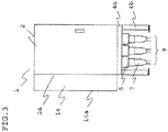
- FIG. 3 is an outline view seen from the right side;
- FIG. 4 is a top surface outline view seen from the top surface;
- FIG. 5 is a base outline view seen from the base.
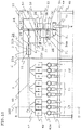
- FIG. 6 is a perspective view showing the whole configuration seen from the front;
- FIG. 7 is a relevant part view seen from an A-A portion of FIG. 6 ;
- FIG. 8 is a relevant part view seen from a B-B portion of FIG. 6 .
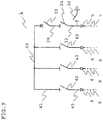
- FIG. 9 is a single line diagram of the gas insulated switchgear.
- a gas insulated switchgear 1 includes: a first gas tank 2 serving as a gas tank in which a circuit breaker 20, a first disconnecting switch 24, and a earthing switch 30 are contained; a second gas tank 3 in which a busbar 40 and a second disconnecting switch 42 are contained; a base frame 4 (a frame portion 4a, a frame portion 4b) on which the first gas tank 2 and the second gas tank 3 connected to each other at a connection portion C are placed; a cable terminal 5 serving as a first external lead-out circuit which passes through a base portion of the first gas tank 2 and is connected to the earthing switch 30 in the first gas tank 2; a cable terminal 6 serving as a second external lead-out circuit which passes through a base portion of the second gas tank 3 and is connected to the second disconnecting switch 42 in the second gas tank 3; a power cable 7 connected to the cable terminal 5; a power cable 8 connected to the cable terminal 6; a first circuit 9 composed of three phase (three) power
- insulating gas sulphur hexafluoride (SF6), dry air, or the like is filled in the first gas tank 2 and the second gas tank 3.
- SF6 sulphur hexafluoride
- dry air or the like is filled in the first gas tank 2 and the second gas tank 3.
- the first circuit 9 is composed of three cable terminals 5; and the second circuit 10, the third circuit 11, and the fourth circuit 12 are each composed of three cable terminals 6.
- Three cable terminals 5 and 6 are arranged at the apexes of each triangle on the base portion of the first gas tank 2 and the second gas tank 3.
- the arrangement is made such that central phases of three cable terminals 5 and 6 are displaced in a lateral direction so as to reduce a dimension in a depth direction (a dimension in the vertical direction of FIG. 5 ). Further, the second circuit 10, the third circuit 11, and the fourth circuit 12 are arranged so as to be in line in the right and the left directions to be a configuration elongated to the right and to the left.
- the circuit breakers 20, the first disconnecting switches 24, and the earthing switches 30 are operated from the right side by the driving portions 52, 53, and 54, respectively, placed in the operation portion 15 on the right side; and the second disconnecting switches 42 are operated from the front by the driving portion 55 placed in the operation portion 13 on the front of a front portion 3a of the second gas tank 3.
- control box 14 in which the control circuit 35 is contained is placed on the front of the first gas tank 2; and inspection and operation of the control circuit 35 can be performed by opening a door 14a.
- the circuit breaker 20 is arranged such that the shaft center direction of a driving shaft 23 thereof is parallel to a front portion 2a of the first gas tank 2 of the gas insulated switchgear 1 and horizontal.
- the circuit breaker 20 opens and closes an electric power circuit by a vacuum interrupter 21 such that the driving shaft 23 of the circuit breaker 20 is moved in the horizontal direction by the driving portion 52 to a fixed contact point 21a of the vacuum interrupter 21 to move a movable contact point 21b via an insulation rod 22.
- first disconnecting switch 24 is arranged on the lower side of the circuit breaker 20 and the first disconnecting switch 24 is arranged such that the shaft center of a driving shaft 27 is parallel to the shaft center of the driving shaft 23 of the circuit breaker 20 and horizontal.
- the first disconnecting switch 24 opens and closes an electric power circuit such that the driving shaft 27, which has a current conducting portion between the fixed contact 25 and a sliding contact 26 at a tip end portion, is moved in the horizontal direction to the fixed contact 25 by the driving portion 53 while being made to come in contact with the sliding contact 26.
- a sliding contact 28 mounted on a conductive driving shaft 21c of the movable contact point 21b of the circuit breaker 20 is electrically connected to the fixed contact 25 of the first disconnecting switch 24 by a connection conductor 29.
- the earthing switch 30 is arranged on the lower side of the first disconnecting switch 24 and is made to ground the cable terminal 5 side of the circuit breaker 20 by making a conductive driving shaft 32 come in contact with a fixed contact 31.
- the sliding contact 26 of the first disconnecting switch 24 is electrically connected to the fixed contact 31 of the earthing switch 30 by a connection conductor 33.
- the fixed contact 31 of the earthing switch 30 is electrically connected to the cable terminal 5 by a connection conductor 34.
- the circuit breaker 20, the first disconnecting switch 24, and the earthing switch 30 are attached to a side portion of the first gas tank 2.
- the circuit breaker 20, the first disconnecting switch 24, and the earthing switch 30 are attached to one sheet of a mounting plate 2b; and this mounting plate 2b may be attached to the first gas tank 2 and thus mounting workability of the apparatuses is improved.
- the busbar 40 is electrically connected to the fixed contact point 21a of the circuit breaker 20 at one end thereof; and the other end is extended in the shaft center direction of the driving shaft 23 of the movable contact point 21b of the circuit breaker 20.
- three (three phase) busbars 40 are arranged in parallel with a predetermined distance in the horizontal direction. Electrical connection is made from three busbars 40 to three second disconnecting switches 42 corresponding to the second circuit 10, the third circuit 11, and the fourth circuit 12 by connection conductors 41, respectively.
- the second disconnecting switches 42 are electrically connected to the cable terminals 6 of the second circuit 10, the third circuit 11, and the fourth circuit 12 by connection conductors 43, respectively.
- a driving shaft 46 of the second disconnecting switch 42 is arranged so as to be orthogonal to the horizontally extending direction of the busbars 40. More specifically, the moving direction of the driving shaft 46 having a current conducting portion between a fixed contact 44 and a sliding contact 45 at a tip end portion of the second disconnecting switch 42 is orthogonal to the moving direction of the driving shaft 23 of the circuit breaker 20 or the moving direction of the driving shaft 27 of the first disconnecting switch 24.
- the driving shaft 46 is made to move in the vertical (front-back) direction with respect to the front portion 3a of the second gas tank 3 by the driving portion 55 placed in the operation portion 13, and the driving shaft 46 is connected to and disconnected from the fixed contact 44, thereby opening and closing an electric power circuit. Furthermore, the sliding contact 45 coming in contact with the driving shaft 46 is electrically connected to the connection conductor 41.
- the second disconnecting switch 42 is attached to the front portion 3a of the second gas tank 3.
- a plurality of the second disconnecting switches 42 are attached to one sheet of a mounting plate 3b; and this mounting plate 3b may be attached to the front of the second gas tank 3 and thus mounting workability of the apparatuses is improved.
- FIG. 9 shows a single line diagram (circuit diagram) of the gas insulated switchgear 1 according to Embodiment 1. Switching of necessary electrical connection is made between the first circuit 9 and the second circuit 10, the third circuit 11, and the fourth circuit 12 by opening and closing operation of the circuit breaker 20, the first disconnecting switch 24, and the second disconnecting switch 42.
- the circuit breaker 20 whose dimension in the driving shaft direction is the largest among constitutional elements used in the gas insulated switchgear 1 is arranged so that the direction of the driving shaft 23 is parallel to the front portion 2a of the first gas tank 2; and thus, the depth dimension of the system of the gas insulated switchgear 1 can be shortened and the gas insulated switchgear 1 can be installed even at a place where the depth dimension is constrained as the shape of the floor to be installed.
- the driving shafts 46 of the second disconnecting switches 42 which need a plurality sets of three-phase constitutional disconnecting switches, are made to orthogonalize with respect to the driving shafts 23 of the circuit breakers 20 and the driving portion 55 of the second disconnecting switches 42 is placed on the front portion 3a side of the second gas tank 3; and thus, there is an effect that operation and inspection of the second disconnecting switches 42 can be easily carried out.
- the gas insulated switchgear includes external lead-out circuits which are led out from the disconnecting switch and the circuit breaker and are for connecting to external apparatuses (devices on the power receiving side, apparatuses on the power supplying side, a generator, and the like).
- These external lead-out circuits are generally arranged so as to be capable of connecting by power cables from the back of the gas insulated switchgear, thereby causing an increase in outline dimensions of the gas insulated switchgear; whereas, in the gas insulated switchgear 1 according to the present embodiment, the cable terminals 5 and 6 serving as the external lead-out circuits are provided on the base portion of the gas tank 2 and 3.
- the length necessary for the cable terminals 5 and 6 can be shortened and, additionally, a degree of freedom in arrangement of apparatuses necessary for the configuration of the gas insulated switchgear 1 is increased and a floor area necessary for installation can be reduced.
- the second disconnecting switches 42 are arranged on the lower side of the busbar 40 and the circuit breaker 20 and the first disconnecting switch 24 are arranged in the lateral direction seen from the front.
- the whole height of the system of the gas insulated switchgear 1 can be lowered and this is effective in the case of being installed at a place whose height is constrained.
- the constitutional apparatus may be one unit in the case of three-phase apparatus; however, the number of constitutional apparatuses in the case of a single-phase apparatus is determined in accordance with the number of phases, for example, three single-phase apparatuses are used in the case of a three-phase circuit.
- FIG. 12 , FIG. 13 , FIG. 14, and FIG. 15 show the three-phase circuit breaker, the three-phase disconnecting switch, the single-phase circuit breaker, and the single-phase disconnecting switch, respectively.
- the circuit breaker 20 includes: the mounting plate 2b to be attached to the first gas tank 2; a circuit breaker extinction chamber 56 in which an interruption portion is contained in a cylindrical case; and the driving portion 52 which drives the contact point in the circuit breaker extinction chamber 56.
- three circuit breaker extinction chambers 56 are arranged in parallel with each other with respect to the mounting plate 2b to form extinction chambers for three phases as shown in FIG. 12 and this is operated such that the contact points in three phase circuit breaker extinction chambers 56 are opening/closing-driven by one driving portion 52 attached on the opposite side of the mounting plate 2b.
- one circuit breaker extinction chamber 56 is arranged with respect to the mounting plate 2b as shown in FIG. 14 and this is operated such that the contact point in the circuit breaker extinction chamber 56 is opening/closing-driven by one driving portion 52 attached on the opposite side of the mounting plate 2b. Furthermore, an internal main circuit in the circuit breaker extinction chamber 56 is connected to an external main circuit by a terminal 57.
- the first disconnecting switch 24 includes: the mounting plate 2b to be attached to the first gas tank 2; a disconnecting switch extinction chamber 58 in which an opening and closing portion of the disconnecting switch is contained in a cylindrical case; and the driving portion 53 which drives the contact point in the disconnecting switch extinction chamber 58.
- three disconnecting switch extinction chambers 58 are arranged in parallel with each other with respect to the mounting plate 2b to form extinction chambers for three phases as shown in FIG. 13 and this is operated such that the contact points in three disconnecting switch extinction chambers 58 are opening/closing-driven by one driving portion 53 attached on the opposite side of the mounting plate 2b.
- one disconnecting switch extinction chamber 58 is arranged with respect to the mounting plate 2b as shown in FIG. 15 and this is operated such that the contact point in the disconnecting switch extinction chamber 58 is opening/closing-driven by one driving portion 53 attached on the opposite side of the mounting plate 2b. Furthermore, an internal main circuit in the disconnecting switch extinction chamber 58 is connected to an external main circuit by a terminal 59.
- the second disconnecting switch 42 is arranged such that the driving shaft 46 thereof is orthogonal to the driving shaft 23 of the circuit breaker 2; however, the second disconnecting switch 42 may be arranged such that the driving shaft 46 thereof is parallel to the driving shaft 23 of the circuit breaker 20.
- the respective sets may be arranged in parallel in the vertical direction and mounted on a side portion of the gas tank 3 so as not to elongate the dimension in the depth direction.
- the second disconnecting switch 42 may be arranged such that the driving shaft 46 is placed in the vertical direction so that the driving portion 55 is placed at a top surface portion of the gas tank 3.
- the longitudinal direction of the circuit breaker (the moving direction of the driving shaft) is arranged parallel to the front portion of the gas insulated switchgear and horizontal, thereby having an effect that the length in the depth direction of the gas insulated switchgear can be shortened.
- FIG. 10 is a perspective view showing an internal configuration seen from the front of a gas insulated switchgear 100 according to Embodiment 2.
- FIG. 11 is a relevant part view seen from a D-D portion of FIG. 10 .
- Differences between the gas insulated switchgear 1 of Embodiment 1 and the gas insulated switchgear 100 of Embodiment 2 are such that the power cables 7 and 8 are connected in a state where the power cables are linearly raised upward from the base of the gas tanks 2 and 3 in Embodiment 1.
- power cables 71 and 81 each shaped in an L shape are used in Embodiment 2, the power cable 71 is connected to a side portion 2d of a gas tank 2 and the power cable 81 is connected to a front portion 3a of a gas tank 3.
- Other constitutional elements are the same as Embodiment 1 and therefore their description will be omitted.
- the power cable 71 is connected to a cable terminal 51 serving as a first external lead-out circuit; and the power cable 81 is connected to a cable terminal 61 serving as a second external lead-out circuit.
- the cable terminal 51 is connected to a first disconnecting switch 24 by a connection conductor 34a; and the cable terminal 61 is connected to a second disconnecting switch 42 by a connection conductor 43a.
- the third circuit 11, and the fourth circuit 12 even when the power cables 81 are applied to connect from the front portion 3a of the second gas tank 3 of the gas insulated switchgear 100, a protrusion portion of the power cable 81 in the depth (front) direction from the gas tank 3 is shorter than the operation portion 13 to be suppressed to the minimum; and therefore, the outline dimensions of the gas insulated switchgear 100 is not influenced.
- connection work of the power cables 7 and 8 needs to be performed at a narrow place near the base of the gas tanks 2 and 3 and the base frame 4 on which the gas tanks 2 and 3 are placed needs to be heightened.
- connection work of the power cables 71 and 81 can be carried out at side portions of the gas tanks 2 and 3; and therefore, there is an effect that work efficiency can be improved and the height dimension of the gas insulated switchgear 100 can be further reduced.
- the gas insulated switchgear according to Embodiment 2 has an effect that the length in the depth direction of the gas insulated switchgear can be shortened and the shape of the power cable is the L shape.
- connection work of the power cables can be performed from the side portions of the gas tanks and the work efficiency can be improved.
- FIG. 16 shows a plan view of an electrical compartment 1001 of a wind turbine 1000 of the wind-power generation system on which the gas insulated switchgear 1 or 100 is installed.
- gas insulated switchgear of the present invention can be installed even at such a narrow installation space whose depth dimension is short.
Landscapes
- Engineering & Computer Science (AREA)
- Power Engineering (AREA)
- Gas-Insulated Switchgears (AREA)
Claims (12)
- Appareillage de commutation à isolation gazeuse (1, 100) dans lequel un coupe-circuit (20) et des commutateurs de déconnexion (24, 42) sont contenus dans des réservoirs à gaz (2, 3) remplis avec un gaz isolant, l'appareillage de commutation à isolation gazeuse (1, 100) comprenant :- un coupe-circuit (20) qui est contenu dans le réservoir à gaz (2), qui a une portion d'entraînement (52) qui entraîne un arbre d'entraînement (23), et qui est agencé de telle façon que l'arbre d'entraînement (23) est parallèle à une portion frontale (2a) du réservoir à gaz (2) et horizontal ;- un premier commutateur de déconnexion (24) qui est contenu dans le réservoir à gaz (2),
qui a une portion d'entraînement (53) qui entraîne un arbre d'entraînement (27),
et qui est électriquement connecté à une extrémité du coupe-circuit (20) ;- une barre omnibus (45) qui est contenue dans le réservoir à gaz (3), et qui est agencée pour être connectée électriquement à l'autre extrémité du coupe-circuit (20) ;- des seconds commutateurs de déconnexion (42) d'au moins un groupe, les seconds commutateurs de déconnexion (42) étant contenus dans le réservoir à gaz (3), ayant une portion d'entraînement (55) qui entraîne un arbre d'entraînement (46), et étant électriquement connectés à la barre omnibus (40) ;- un premier circuit de sortie externe (5) qui est connecté électriquement au premier commutateur de déconnexion (24), et qui passe à travers la surface de paroi du réservoir à gaz (2) pour être mené à l'extérieur du réservoir à gaz (2) ;- des seconds circuits de sortie externes (6) correspondant au nombre de groupes de seconds commutateurs de déconnexion (42), les seconds circuits de sortie externes (6) étant électriquement connectés au second commutateur de déconnexion (42), et passant à travers la surface de paroi du réservoir à gaz (3) pour être menés à l'extérieur du réservoir à gaz (3) ; et
dans lequel la barre omnibus (45) s'étend dans la direction horizontale par rapport à la direction de l'arbre d'entraînement (23) du coupe-circuit (20), et les seconds commutateurs de déconnexion (42) sont agencés sur le côté inférieur de la barre omnibus (40). - Appareillage de commutation à isolation gazeuse (1, 100) selon la revendication 1, dans lequel- le coupe-circuit (20) est un coupe-circuit à phase unique et un nombre de coupe-circuits à phase unique prévus correspond un nombre de phases, les coupe-circuits à phase unique étant contenus dans le réservoir à gaz (2), ayant une portion d'entraînement (52) qui entraîne un arbre d'entraînement (23), et étant agencé de telle façon que l'arbre d'entraînement (23) est parallèle à une portion frontale (2a) du réservoir à gaz (2) et horizontal ;- le premier commutateur de déconnexion (24) est un premier commutateur de déconnexion à phase unique et un nombre de premiers commutateurs de déconnexion à phase unique correspond au nombre de phases, les premiers commutateurs de déconnexion à phase unique étant contenus dans le réservoir gaz (2), ayant une portion d'entraînement (53) qui entraîne un arbre d'entraînement (27), et étant électriquement connecté à chacun des coupe-circuits (20) ;- les barres omnibus (40), dont le nombre correspond au nombre de phases, les barres omnibus (40) étant contenues dans le réservoir à gaz (3) et étant agencées pour être électriquement connectées aux autres extrémités des coupe-circuits (20) ;- les seconds commutateurs de déconnexion, dont le nombre correspond au nombre de phases d'au moins un groupe, les seconds commutateurs de déconnexion (42) étant contenus dans le réservoir gaz (3), ayant une portion d'entraînement (55) qui entraîne un arbre d'entraînement (46), et étant électriquement connectés aux barres omnibus (40) ;- les premiers circuits de sortie externes (5), dont le nombre correspond au nombre de phases, les premiers circuits de sortie externes (5) étant électriquement connectés au premier commutateur de déconnexion (24), et passant à travers la surface de paroi du réservoir à gaz (2) pour être menés à l'extérieur du réservoir à gaz (2) ; et- les seconds circuits de sortie externes (6), dont le nombre correspond au nombre de phases du nombre de groupes correspondant au nombre de groupes des seconds commutateurs de déconnexion (42), les seconds circuits de sortie externes (6) étant connectés électriquement aux seconds commutateurs de déconnexion (42), et passant à travers la surface de la paroi du réservoir à gaz (3) pour être menés vers l'extérieur du réservoir à gaz (3).
- Appareillage de commutation à isolation gazeuse (1, 100)
selon la revendication 1 ou 2,
dans lequel les barres omnibus (40) sont agencées parallèles dans un état de manière à être parallèles à la portion frontale (3a) du réservoir à gaz (3) et à s'étendre dans une direction horizontale. - Appareillage de commutation à isolation gazeuse (1, 100)
selon la revendication 1 ou 2,
dans lequel le premier commutateur de déconnexion (24) est agencé de telle façon que l'arbre d'entraînement (27) de celui-ci est placé horizontalement et sur le côté inférieur ou le côté supérieur du coupe-circuit (20). - Appareillage de commutation à isolation gazeuse (1, 100)
selon la revendication 1 ou 2,
dans lequel le second commutateur de déconnexion (42) est agencé de telle façon que l'arbre d'entraînement (46) de celui-ci est placé orthogonal à l'arbre d'entraînement (28) du coupe-circuit (20) et horizontalement. - Appareillage de commutation à isolation gazeuse (1, 100)
selon la revendication 5,
dans lequel, dans le cas où les seconds commutateurs de déconnexion (42) sont en une pluralité de groupes, les groupes respectifs sont agencés parallèles par rapport à une direction horizontale. - Appareillage de commutation à isolation gazeuse (1)
selon la revendication 6,
dans lequel les seconds circuits de sortie externes (6) sont placés de telle façon que les groupes respectifs correspondants aux seconds commutateurs de déconnexion (42) sont disposés en rangée à une portion de base du réservoir à gaz (3). - Appareillage de commutation à isolation gazeuse (100)
selon la revendication 6,
dans lequel les seconds circuits de sortie externe (6) sont placés de telle façon que les groupes respectifs correspondants aux seconds commutateurs de déconnexion (42) sont disposés en rangée à la portion frontale du réservoir à gaz (3). - Appareillage de commutation à isolation gazeuse (1, 100)
selon la revendication 1 ou 2,
dans lequel le second commutateur de déconnexion (42) est agencé de telle façon que l'arbre d'entraînement (46) de celui-ci est parallèle à l'arbre d'entraînement (23) du coupe-circuit (20). - Appareillage de commutation à isolation gazeuse (1, 100)
selon la revendication 9,
dans lequel, dans le cas où les seconds commutateurs de déconnexion (42) sont en une pluralité de groupes, les groupes respectifs sont agencés parallèles dans une direction verticale. - Appareillage de commutation à isolation gazeuse (1, 100)
selon l'une quelconque des revendications 1 à 10,
dans lequel le réservoir à gaz inclut deux réservoirs à gaz indépendants (2, 3) ; un premier réservoir à gaz (2) contient le coupe-circuit (20), le premier commutateur de déconnexion (24), et le premier circuit de sortie externe (5) ; et un second réservoir à gaz (3) contient la barre omnibus (40), le second commutateur de déconnexion (42), et le second circuit de sortie externe (6). - Appareillage de commutation à isolation gazeuse (1, 100)
selon l'une quelconque des revendications 1 à 11,
dans lequel l'appareillage de commutation à isolation gazeuse (1 ou 100) est installé dans une turbine éolienne (1000) d'un système de génération d'énergie éolienne.
Applications Claiming Priority (2)
| Application Number | Priority Date | Filing Date | Title |
|---|---|---|---|
| JP2013025803 | 2013-02-13 | ||
| PCT/JP2014/052417 WO2014125948A1 (fr) | 2013-02-13 | 2014-02-03 | Appareillage de connexion à isolation gazeuse |
Publications (3)
| Publication Number | Publication Date |
|---|---|
| EP2958205A1 EP2958205A1 (fr) | 2015-12-23 |
| EP2958205A4 EP2958205A4 (fr) | 2016-09-14 |
| EP2958205B1 true EP2958205B1 (fr) | 2019-03-27 |
Family
ID=51353956
Family Applications (1)
| Application Number | Title | Priority Date | Filing Date |
|---|---|---|---|
| EP14751069.7A Active EP2958205B1 (fr) | 2013-02-13 | 2014-02-03 | Appareillage de connexion à isolation gazeuse |
Country Status (6)
| Country | Link |
|---|---|
| US (1) | US9355792B2 (fr) |
| EP (1) | EP2958205B1 (fr) |
| JP (1) | JP5602977B1 (fr) |
| CN (1) | CN105075039B (fr) |
| DK (1) | DK2958205T3 (fr) |
| WO (1) | WO2014125948A1 (fr) |
Families Citing this family (6)
| Publication number | Priority date | Publication date | Assignee | Title |
|---|---|---|---|---|
| WO2015186244A1 (fr) * | 2014-06-06 | 2015-12-10 | 三菱電機株式会社 | Appareillage de commutation |
| EP3280016A4 (fr) * | 2015-04-02 | 2018-11-07 | Mitsubishi Electric Corporation | Appareillage de commutation à isolation gazeuse |
| US11095099B2 (en) * | 2018-03-14 | 2021-08-17 | Mitsubishi Electric Corporation | Gas-insulated switching device |
| ES2887257T3 (es) * | 2018-12-19 | 2021-12-22 | Abb Schweiz Ag | Aparato de conmutación o aparato de control |
| US12057683B2 (en) * | 2022-04-21 | 2024-08-06 | Jst Power Equipment, Inc. | Circuit breaker with single phase control |
| CN117559276B (zh) * | 2023-11-10 | 2024-09-17 | 广东明阳电气股份有限公司 | 海上风电用组合电器 |
Family Cites Families (21)
| Publication number | Priority date | Publication date | Assignee | Title |
|---|---|---|---|---|
| US2218554A (en) * | 1936-08-24 | 1940-10-22 | Allen M Rossman | Electric switchgear |
| DE3421265A1 (de) * | 1983-06-10 | 1984-12-13 | Mitsubishi Denki K.K., Tokio/Tokyo | Schaltgeraet |
| JPS6022404A (ja) * | 1983-07-19 | 1985-02-04 | 日新電機株式会社 | ガス絶縁開閉装置 |
| DE8717730U1 (de) * | 1987-05-06 | 1989-11-30 | Sachsenwerk AG, 8400 Regensburg | Metallgekapselte, mit Druckgas gefüllte, mehrphasige Hochspannungsschaltanlage |
| DE3915948A1 (de) * | 1989-05-12 | 1990-11-15 | Siemens Ag | Lastschaltanlage mit einem dreistellungsschalter |
| DE4211154A1 (de) * | 1992-03-31 | 1993-10-07 | Siemens Ag | Gasisolierte Schaltanlage mit einem Vakuumschalter |
| JP2001352624A (ja) * | 2000-06-02 | 2001-12-21 | Mitsubishi Electric Corp | ガス絶縁開閉装置のブッシング |
| JP2001352623A (ja) * | 2000-06-02 | 2001-12-21 | Mitsubishi Electric Corp | ガス絶縁開閉装置 |
| JP2001352621A (ja) * | 2000-06-02 | 2001-12-21 | Mitsubishi Electric Corp | ガス絶縁開閉装置 |
| JP2002159109A (ja) * | 2000-11-20 | 2002-05-31 | Mitsubishi Electric Corp | ガス絶縁開閉装置 |
| JP2002171624A (ja) * | 2000-11-30 | 2002-06-14 | Mitsubishi Electric Corp | ガス封入形開閉装置 |
| JP4193099B2 (ja) * | 2002-07-31 | 2008-12-10 | 富士電機システムズ株式会社 | ガス絶縁開閉装置 |
| JP4329923B2 (ja) * | 2002-10-31 | 2009-09-09 | 三菱電機株式会社 | ガス絶縁スイッチギヤ |
| TWI228339B (en) * | 2002-11-06 | 2005-02-21 | Mitsubishi Electric Corp | Metal-enclosed switchgear |
| JP4237591B2 (ja) * | 2003-09-17 | 2009-03-11 | 株式会社日立製作所 | ガス絶縁開閉装置 |
| DE102005029600A1 (de) * | 2004-06-28 | 2006-01-19 | Abb Technology Ag | Gasisolierte Mittelspannungs-Schaltanlage |
| JP4468768B2 (ja) * | 2004-08-27 | 2010-05-26 | 三菱電機株式会社 | 密閉形電力開閉装置 |
| JP4572145B2 (ja) | 2005-07-15 | 2010-10-27 | 三菱電機株式会社 | ガス絶縁スイッチギヤ |
| CN201118136Y (zh) * | 2007-11-01 | 2008-09-17 | 天水长城开关厂有限公司 | 固定式金属封闭配电开关柜 |
| JP5122003B2 (ja) * | 2009-08-25 | 2013-01-16 | 三菱電機株式会社 | 開閉装置 |
| CN102044849A (zh) * | 2009-10-16 | 2011-05-04 | 山东鲁亿通电气设备有限公司 | 一种共箱式气体绝缘金属封闭开关装置 |
-
2014
- 2014-02-03 JP JP2014524982A patent/JP5602977B1/ja active Active
- 2014-02-03 DK DK14751069.7T patent/DK2958205T3/da active
- 2014-02-03 WO PCT/JP2014/052417 patent/WO2014125948A1/fr active Application Filing
- 2014-02-03 CN CN201480008487.6A patent/CN105075039B/zh active Active
- 2014-02-03 US US14/443,753 patent/US9355792B2/en active Active
- 2014-02-03 EP EP14751069.7A patent/EP2958205B1/fr active Active
Non-Patent Citations (1)
| Title |
|---|
| None * |
Also Published As
| Publication number | Publication date |
|---|---|
| WO2014125948A1 (fr) | 2014-08-21 |
| JP5602977B1 (ja) | 2014-10-08 |
| EP2958205A1 (fr) | 2015-12-23 |
| DK2958205T3 (da) | 2019-05-06 |
| CN105075039A (zh) | 2015-11-18 |
| EP2958205A4 (fr) | 2016-09-14 |
| JPWO2014125948A1 (ja) | 2017-02-02 |
| CN105075039B (zh) | 2016-12-28 |
| US9355792B2 (en) | 2016-05-31 |
| US20150340174A1 (en) | 2015-11-26 |
Similar Documents
| Publication | Publication Date | Title |
|---|---|---|
| KR101286812B1 (ko) | 스위치 기어 | |
| EP2958205B1 (fr) | Appareillage de connexion à isolation gazeuse | |
| US6759616B2 (en) | Gas insulated switchgear | |
| WO2017107744A1 (fr) | Circuit principal d'appareillage de commutation isolé solide et appareillage de commutation isolé solide utilisant le circuit principal | |
| CN101540484B (zh) | 开关机构 | |
| EP3062403B1 (fr) | Appareillage de commutation à isolation par gaz | |
| EP2833494B1 (fr) | Appareil de commutateur isolé par un gaz | |
| KR20120124020A (ko) | 전기 전력 스위치, 및 전력 스위치를 포함하는 제어 패널 | |
| JP2011066962A (ja) | ガス絶縁スイッチギヤ | |
| EP3641082B1 (fr) | Appareillage de commutation à isolation gazeuse | |
| KR20150006870A (ko) | 스위치 기어 및 스위치 기어의 조립 방법 | |
| JP2012015009A (ja) | 高電圧開閉装置 | |
| JP6398651B2 (ja) | スイッチギヤ | |
| JP5868308B2 (ja) | ガス絶縁開閉装置 | |
| US10297987B2 (en) | Gas insulated switchgear |
Legal Events
| Date | Code | Title | Description |
|---|---|---|---|
| PUAI | Public reference made under article 153(3) epc to a published international application that has entered the european phase |
Free format text: ORIGINAL CODE: 0009012 |
|
| 17P | Request for examination filed |
Effective date: 20150810 |
|
| AK | Designated contracting states |
Kind code of ref document: A1 Designated state(s): AL AT BE BG CH CY CZ DE DK EE ES FI FR GB GR HR HU IE IS IT LI LT LU LV MC MK MT NL NO PL PT RO RS SE SI SK SM TR |
|
| AX | Request for extension of the european patent |
Extension state: BA ME |
|
| DAX | Request for extension of the european patent (deleted) | ||
| A4 | Supplementary search report drawn up and despatched |
Effective date: 20160812 |
|
| RIC1 | Information provided on ipc code assigned before grant |
Ipc: H02B 13/02 20060101AFI20160808BHEP Ipc: H01H 33/12 20060101ALI20160808BHEP Ipc: H02B 13/035 20060101ALI20160808BHEP |
|
| REG | Reference to a national code |
Ref country code: DE Ref legal event code: R079 Ref document number: 602014043654 Country of ref document: DE Free format text: PREVIOUS MAIN CLASS: H02B0013020000 Ipc: H01H0033120000 |
|
| RIC1 | Information provided on ipc code assigned before grant |
Ipc: H02B 13/035 20060101ALI20180711BHEP Ipc: H01H 33/12 20060101AFI20180711BHEP Ipc: H01H 31/00 20060101ALN20180711BHEP Ipc: H01H 33/666 20060101ALN20180711BHEP |
|
| GRAP | Despatch of communication of intention to grant a patent |
Free format text: ORIGINAL CODE: EPIDOSNIGR1 |
|
| STAA | Information on the status of an ep patent application or granted ep patent |
Free format text: STATUS: GRANT OF PATENT IS INTENDED |
|
| RIC1 | Information provided on ipc code assigned before grant |
Ipc: H01H 33/666 20060101ALN20180806BHEP Ipc: H01H 31/00 20060101ALN20180806BHEP Ipc: H01H 33/12 20060101AFI20180806BHEP Ipc: H02B 13/035 20060101ALI20180806BHEP |
|
| INTG | Intention to grant announced |
Effective date: 20180821 |
|
| GRAS | Grant fee paid |
Free format text: ORIGINAL CODE: EPIDOSNIGR3 |
|
| GRAA | (expected) grant |
Free format text: ORIGINAL CODE: 0009210 |
|
| STAA | Information on the status of an ep patent application or granted ep patent |
Free format text: STATUS: THE PATENT HAS BEEN GRANTED |
|
| AK | Designated contracting states |
Kind code of ref document: B1 Designated state(s): AL AT BE BG CH CY CZ DE DK EE ES FI FR GB GR HR HU IE IS IT LI LT LU LV MC MK MT NL NO PL PT RO RS SE SI SK SM TR |
|
| REG | Reference to a national code |
Ref country code: GB Ref legal event code: FG4D |
|
| REG | Reference to a national code |
Ref country code: CH Ref legal event code: EP |
|
| REG | Reference to a national code |
Ref country code: AT Ref legal event code: REF Ref document number: 1114020 Country of ref document: AT Kind code of ref document: T Effective date: 20190415 |
|
| REG | Reference to a national code |
Ref country code: IE Ref legal event code: FG4D |
|
| REG | Reference to a national code |
Ref country code: DE Ref legal event code: R096 Ref document number: 602014043654 Country of ref document: DE |
|
| REG | Reference to a national code |
Ref country code: DK Ref legal event code: T3 Effective date: 20190429 |
|
| PG25 | Lapsed in a contracting state [announced via postgrant information from national office to epo] |
Ref country code: LT Free format text: LAPSE BECAUSE OF FAILURE TO SUBMIT A TRANSLATION OF THE DESCRIPTION OR TO PAY THE FEE WITHIN THE PRESCRIBED TIME-LIMIT Effective date: 20190327 Ref country code: NO Free format text: LAPSE BECAUSE OF FAILURE TO SUBMIT A TRANSLATION OF THE DESCRIPTION OR TO PAY THE FEE WITHIN THE PRESCRIBED TIME-LIMIT Effective date: 20190627 Ref country code: FI Free format text: LAPSE BECAUSE OF FAILURE TO SUBMIT A TRANSLATION OF THE DESCRIPTION OR TO PAY THE FEE WITHIN THE PRESCRIBED TIME-LIMIT Effective date: 20190327 Ref country code: SE Free format text: LAPSE BECAUSE OF FAILURE TO SUBMIT A TRANSLATION OF THE DESCRIPTION OR TO PAY THE FEE WITHIN THE PRESCRIBED TIME-LIMIT Effective date: 20190327 |
|
| REG | Reference to a national code |
Ref country code: NL Ref legal event code: MP Effective date: 20190327 |
|
| PG25 | Lapsed in a contracting state [announced via postgrant information from national office to epo] |
Ref country code: LV Free format text: LAPSE BECAUSE OF FAILURE TO SUBMIT A TRANSLATION OF THE DESCRIPTION OR TO PAY THE FEE WITHIN THE PRESCRIBED TIME-LIMIT Effective date: 20190327 Ref country code: HR Free format text: LAPSE BECAUSE OF FAILURE TO SUBMIT A TRANSLATION OF THE DESCRIPTION OR TO PAY THE FEE WITHIN THE PRESCRIBED TIME-LIMIT Effective date: 20190327 Ref country code: GR Free format text: LAPSE BECAUSE OF FAILURE TO SUBMIT A TRANSLATION OF THE DESCRIPTION OR TO PAY THE FEE WITHIN THE PRESCRIBED TIME-LIMIT Effective date: 20190628 Ref country code: BG Free format text: LAPSE BECAUSE OF FAILURE TO SUBMIT A TRANSLATION OF THE DESCRIPTION OR TO PAY THE FEE WITHIN THE PRESCRIBED TIME-LIMIT Effective date: 20190627 Ref country code: NL Free format text: LAPSE BECAUSE OF FAILURE TO SUBMIT A TRANSLATION OF THE DESCRIPTION OR TO PAY THE FEE WITHIN THE PRESCRIBED TIME-LIMIT Effective date: 20190327 Ref country code: RS Free format text: LAPSE BECAUSE OF FAILURE TO SUBMIT A TRANSLATION OF THE DESCRIPTION OR TO PAY THE FEE WITHIN THE PRESCRIBED TIME-LIMIT Effective date: 20190327 |
|
| REG | Reference to a national code |
Ref country code: AT Ref legal event code: MK05 Ref document number: 1114020 Country of ref document: AT Kind code of ref document: T Effective date: 20190327 |
|
| PG25 | Lapsed in a contracting state [announced via postgrant information from national office to epo] |
Ref country code: ES Free format text: LAPSE BECAUSE OF FAILURE TO SUBMIT A TRANSLATION OF THE DESCRIPTION OR TO PAY THE FEE WITHIN THE PRESCRIBED TIME-LIMIT Effective date: 20190327 Ref country code: PT Free format text: LAPSE BECAUSE OF FAILURE TO SUBMIT A TRANSLATION OF THE DESCRIPTION OR TO PAY THE FEE WITHIN THE PRESCRIBED TIME-LIMIT Effective date: 20190727 Ref country code: RO Free format text: LAPSE BECAUSE OF FAILURE TO SUBMIT A TRANSLATION OF THE DESCRIPTION OR TO PAY THE FEE WITHIN THE PRESCRIBED TIME-LIMIT Effective date: 20190327 Ref country code: CZ Free format text: LAPSE BECAUSE OF FAILURE TO SUBMIT A TRANSLATION OF THE DESCRIPTION OR TO PAY THE FEE WITHIN THE PRESCRIBED TIME-LIMIT Effective date: 20190327 Ref country code: SK Free format text: LAPSE BECAUSE OF FAILURE TO SUBMIT A TRANSLATION OF THE DESCRIPTION OR TO PAY THE FEE WITHIN THE PRESCRIBED TIME-LIMIT Effective date: 20190327 Ref country code: IT Free format text: LAPSE BECAUSE OF FAILURE TO SUBMIT A TRANSLATION OF THE DESCRIPTION OR TO PAY THE FEE WITHIN THE PRESCRIBED TIME-LIMIT Effective date: 20190327 Ref country code: EE Free format text: LAPSE BECAUSE OF FAILURE TO SUBMIT A TRANSLATION OF THE DESCRIPTION OR TO PAY THE FEE WITHIN THE PRESCRIBED TIME-LIMIT Effective date: 20190327 Ref country code: AL Free format text: LAPSE BECAUSE OF FAILURE TO SUBMIT A TRANSLATION OF THE DESCRIPTION OR TO PAY THE FEE WITHIN THE PRESCRIBED TIME-LIMIT Effective date: 20190327 |
|
| PG25 | Lapsed in a contracting state [announced via postgrant information from national office to epo] |
Ref country code: SM Free format text: LAPSE BECAUSE OF FAILURE TO SUBMIT A TRANSLATION OF THE DESCRIPTION OR TO PAY THE FEE WITHIN THE PRESCRIBED TIME-LIMIT Effective date: 20190327 Ref country code: PL Free format text: LAPSE BECAUSE OF FAILURE TO SUBMIT A TRANSLATION OF THE DESCRIPTION OR TO PAY THE FEE WITHIN THE PRESCRIBED TIME-LIMIT Effective date: 20190327 |
|
| PG25 | Lapsed in a contracting state [announced via postgrant information from national office to epo] |
Ref country code: AT Free format text: LAPSE BECAUSE OF FAILURE TO SUBMIT A TRANSLATION OF THE DESCRIPTION OR TO PAY THE FEE WITHIN THE PRESCRIBED TIME-LIMIT Effective date: 20190327 Ref country code: IS Free format text: LAPSE BECAUSE OF FAILURE TO SUBMIT A TRANSLATION OF THE DESCRIPTION OR TO PAY THE FEE WITHIN THE PRESCRIBED TIME-LIMIT Effective date: 20190727 |
|
| REG | Reference to a national code |
Ref country code: DE Ref legal event code: R097 Ref document number: 602014043654 Country of ref document: DE |
|
| PLBE | No opposition filed within time limit |
Free format text: ORIGINAL CODE: 0009261 |
|
| STAA | Information on the status of an ep patent application or granted ep patent |
Free format text: STATUS: NO OPPOSITION FILED WITHIN TIME LIMIT |
|
| PG25 | Lapsed in a contracting state [announced via postgrant information from national office to epo] |
Ref country code: SI Free format text: LAPSE BECAUSE OF FAILURE TO SUBMIT A TRANSLATION OF THE DESCRIPTION OR TO PAY THE FEE WITHIN THE PRESCRIBED TIME-LIMIT Effective date: 20190327 |
|
| 26N | No opposition filed |
Effective date: 20200103 |
|
| PG25 | Lapsed in a contracting state [announced via postgrant information from national office to epo] |
Ref country code: TR Free format text: LAPSE BECAUSE OF FAILURE TO SUBMIT A TRANSLATION OF THE DESCRIPTION OR TO PAY THE FEE WITHIN THE PRESCRIBED TIME-LIMIT Effective date: 20190327 |
|
| REG | Reference to a national code |
Ref country code: CH Ref legal event code: PL |
|
| REG | Reference to a national code |
Ref country code: BE Ref legal event code: MM Effective date: 20200229 |
|
| PG25 | Lapsed in a contracting state [announced via postgrant information from national office to epo] |
Ref country code: MC Free format text: LAPSE BECAUSE OF FAILURE TO SUBMIT A TRANSLATION OF THE DESCRIPTION OR TO PAY THE FEE WITHIN THE PRESCRIBED TIME-LIMIT Effective date: 20190327 Ref country code: LU Free format text: LAPSE BECAUSE OF NON-PAYMENT OF DUE FEES Effective date: 20200203 |
|
| PG25 | Lapsed in a contracting state [announced via postgrant information from national office to epo] |
Ref country code: LI Free format text: LAPSE BECAUSE OF NON-PAYMENT OF DUE FEES Effective date: 20200229 Ref country code: CH Free format text: LAPSE BECAUSE OF NON-PAYMENT OF DUE FEES Effective date: 20200229 |
|
| PG25 | Lapsed in a contracting state [announced via postgrant information from national office to epo] |
Ref country code: IE Free format text: LAPSE BECAUSE OF NON-PAYMENT OF DUE FEES Effective date: 20200203 |
|
| PG25 | Lapsed in a contracting state [announced via postgrant information from national office to epo] |
Ref country code: BE Free format text: LAPSE BECAUSE OF NON-PAYMENT OF DUE FEES Effective date: 20200229 |
|
| PG25 | Lapsed in a contracting state [announced via postgrant information from national office to epo] |
Ref country code: MT Free format text: LAPSE BECAUSE OF FAILURE TO SUBMIT A TRANSLATION OF THE DESCRIPTION OR TO PAY THE FEE WITHIN THE PRESCRIBED TIME-LIMIT Effective date: 20190327 Ref country code: CY Free format text: LAPSE BECAUSE OF FAILURE TO SUBMIT A TRANSLATION OF THE DESCRIPTION OR TO PAY THE FEE WITHIN THE PRESCRIBED TIME-LIMIT Effective date: 20190327 |
|
| PG25 | Lapsed in a contracting state [announced via postgrant information from national office to epo] |
Ref country code: MK Free format text: LAPSE BECAUSE OF FAILURE TO SUBMIT A TRANSLATION OF THE DESCRIPTION OR TO PAY THE FEE WITHIN THE PRESCRIBED TIME-LIMIT Effective date: 20190327 |
|
| P01 | Opt-out of the competence of the unified patent court (upc) registered |
Effective date: 20230512 |
|
| PGFP | Annual fee paid to national office [announced via postgrant information from national office to epo] |
Ref country code: DE Payment date: 20231228 Year of fee payment: 11 Ref country code: GB Payment date: 20240108 Year of fee payment: 11 |
|
| PGFP | Annual fee paid to national office [announced via postgrant information from national office to epo] |
Ref country code: FR Payment date: 20240103 Year of fee payment: 11 Ref country code: DK Payment date: 20240214 Year of fee payment: 11 |