EP2958196A1 - Cable with molded resin - Google Patents
Cable with molded resin Download PDFInfo
- Publication number
- EP2958196A1 EP2958196A1 EP15171050.6A EP15171050A EP2958196A1 EP 2958196 A1 EP2958196 A1 EP 2958196A1 EP 15171050 A EP15171050 A EP 15171050A EP 2958196 A1 EP2958196 A1 EP 2958196A1
- Authority
- EP
- European Patent Office
- Prior art keywords
- molded resin
- cable
- electric wire
- bent
- derivation
- Prior art date
- Legal status (The legal status is an assumption and is not a legal conclusion. Google has not performed a legal analysis and makes no representation as to the accuracy of the status listed.)
- Granted
Links
Images
Classifications
-
- H—ELECTRICITY
- H01—ELECTRIC ELEMENTS
- H01B—CABLES; CONDUCTORS; INSULATORS; SELECTION OF MATERIALS FOR THEIR CONDUCTIVE, INSULATING OR DIELECTRIC PROPERTIES
- H01B7/00—Insulated conductors or cables characterised by their form
- H01B7/17—Protection against damage caused by external factors, e.g. sheaths or armouring
- H01B7/18—Protection against damage caused by wear, mechanical force or pressure; Sheaths; Armouring
- H01B7/24—Devices affording localised protection against mechanical force or pressure
-
- G—PHYSICS
- G01—MEASURING; TESTING
- G01D—MEASURING NOT SPECIALLY ADAPTED FOR A SPECIFIC VARIABLE; ARRANGEMENTS FOR MEASURING TWO OR MORE VARIABLES NOT COVERED IN A SINGLE OTHER SUBCLASS; TARIFF METERING APPARATUS; MEASURING OR TESTING NOT OTHERWISE PROVIDED FOR
- G01D11/00—Component parts of measuring arrangements not specially adapted for a specific variable
- G01D11/24—Housings ; Casings for instruments
- G01D11/245—Housings for sensors
-
- H—ELECTRICITY
- H01—ELECTRIC ELEMENTS
- H01B—CABLES; CONDUCTORS; INSULATORS; SELECTION OF MATERIALS FOR THEIR CONDUCTIVE, INSULATING OR DIELECTRIC PROPERTIES
- H01B3/00—Insulators or insulating bodies characterised by the insulating materials; Selection of materials for their insulating or dielectric properties
- H01B3/18—Insulators or insulating bodies characterised by the insulating materials; Selection of materials for their insulating or dielectric properties mainly consisting of organic substances
- H01B3/30—Insulators or insulating bodies characterised by the insulating materials; Selection of materials for their insulating or dielectric properties mainly consisting of organic substances plastics; resins; waxes
- H01B3/303—Macromolecular compounds obtained by reactions forming a linkage containing nitrogen with or without oxygen or carbon in the main chain of the macromolecule, not provided for in groups H01B3/38 or H01B3/302
- H01B3/305—Polyamides or polyesteramides
-
- H—ELECTRICITY
- H01—ELECTRIC ELEMENTS
- H01B—CABLES; CONDUCTORS; INSULATORS; SELECTION OF MATERIALS FOR THEIR CONDUCTIVE, INSULATING OR DIELECTRIC PROPERTIES
- H01B3/00—Insulators or insulating bodies characterised by the insulating materials; Selection of materials for their insulating or dielectric properties
- H01B3/18—Insulators or insulating bodies characterised by the insulating materials; Selection of materials for their insulating or dielectric properties mainly consisting of organic substances
- H01B3/30—Insulators or insulating bodies characterised by the insulating materials; Selection of materials for their insulating or dielectric properties mainly consisting of organic substances plastics; resins; waxes
- H01B3/42—Insulators or insulating bodies characterised by the insulating materials; Selection of materials for their insulating or dielectric properties mainly consisting of organic substances plastics; resins; waxes polyesters; polyethers; polyacetals
- H01B3/421—Polyesters
- H01B3/422—Linear saturated polyesters derived from dicarboxylic acids and dihydroxy compounds
-
- H—ELECTRICITY
- H01—ELECTRIC ELEMENTS
- H01B—CABLES; CONDUCTORS; INSULATORS; SELECTION OF MATERIALS FOR THEIR CONDUCTIVE, INSULATING OR DIELECTRIC PROPERTIES
- H01B3/00—Insulators or insulating bodies characterised by the insulating materials; Selection of materials for their insulating or dielectric properties
- H01B3/18—Insulators or insulating bodies characterised by the insulating materials; Selection of materials for their insulating or dielectric properties mainly consisting of organic substances
- H01B3/30—Insulators or insulating bodies characterised by the insulating materials; Selection of materials for their insulating or dielectric properties mainly consisting of organic substances plastics; resins; waxes
- H01B3/47—Insulators or insulating bodies characterised by the insulating materials; Selection of materials for their insulating or dielectric properties mainly consisting of organic substances plastics; resins; waxes fibre-reinforced plastics, e.g. glass-reinforced plastics
-
- H—ELECTRICITY
- H01—ELECTRIC ELEMENTS
- H01R—ELECTRICALLY-CONDUCTIVE CONNECTIONS; STRUCTURAL ASSOCIATIONS OF A PLURALITY OF MUTUALLY-INSULATED ELECTRICAL CONNECTING ELEMENTS; COUPLING DEVICES; CURRENT COLLECTORS
- H01R13/00—Details of coupling devices of the kinds covered by groups H01R12/70 or H01R24/00 - H01R33/00
- H01R13/58—Means for relieving strain on wire connection, e.g. cord grip, for avoiding loosening of connections between wires and terminals within a coupling device terminating a cable
- H01R13/5833—Means for relieving strain on wire connection, e.g. cord grip, for avoiding loosening of connections between wires and terminals within a coupling device terminating a cable the cable being forced in a tortuous or curved path, e.g. knots in cable
-
- H—ELECTRICITY
- H01—ELECTRIC ELEMENTS
- H01R—ELECTRICALLY-CONDUCTIVE CONNECTIONS; STRUCTURAL ASSOCIATIONS OF A PLURALITY OF MUTUALLY-INSULATED ELECTRICAL CONNECTING ELEMENTS; COUPLING DEVICES; CURRENT COLLECTORS
- H01R13/00—Details of coupling devices of the kinds covered by groups H01R12/70 or H01R24/00 - H01R33/00
- H01R13/58—Means for relieving strain on wire connection, e.g. cord grip, for avoiding loosening of connections between wires and terminals within a coupling device terminating a cable
- H01R13/5845—Means for relieving strain on wire connection, e.g. cord grip, for avoiding loosening of connections between wires and terminals within a coupling device terminating a cable the strain relief being achieved by molding parts around cable and connections
Definitions
- the invention relates to a cable with a molded resin that a part of the cable in a longitudinal direction thereof is covered by a molded resin.
- a cable with a molded resin is known in which an electronic component connected to an end part of a cable is covered by a molded resin (see e.g. JP-A-H09-35820 ).
- the cable disclosed in JP-A-H09-35820 includes a connector part to be connected to terminals of an electronic equipment, a circuit board attached to the connector part, electronic components mounted on the circuit board, a case covering the electronic components, a cable to be electrically connected to the connector part via the circuit board, and a molded resin covering the connection end part side of the cable.
- the cable is a coaxial cable, and is configured such that internal conducting wires and external conducting wires exposed at the end part are respectively connected to circuit patterns formed on the circuit board.
- the molded resin integrally covers the connection end part, the circuit board and the electronic components in a state of being covered by the case.
- the cable disclosed in JP-A-H09-35820 may have a risk that the molded resin can usually absorb a tensile force applied to the cable from outside, but a contact failure may occur at the connection parts of the internal conducting wires and external conducting wires to the circuit pattern if a strong tensile force acts thereon.
- a cable with a molded resin comprises:
- a cable with a molded resin can be provided that prevents a tensile force from acting on the end part of the cable even when the tensile force is applied to the cable outside the molded resin.
- a sensor module according to the first embodiment of the invention is used, for example, as a vehicle mounted sensor or the like mounted on vehicles so as to measure a rotation number of a wheel, a rotation angle of a handle and the like in vehicles.
- the sensor module is one aspect of the cable with a molded resin of the invention.
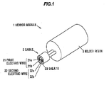
- FIG . 1 is a perspective view schematically showing an appearance of a sensor module according to a first embodiment of the invention.
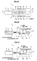
- FIG.2 A is a top view schematically showing a configuration example of the sensor module according to the first embodiment of the invention
- FIG.2 B is a cross-sectional view taken along the line A-A in FIG.2 A
- FIG.2 C is a side view schematically showing a configuration example of the sensor module according to the first embodiment of the invention.
- FIGs.2 A to 2 C show the molded resin 3 by a two-dot chain line.
- the sensor module 1 includes the cable 2, the molded resin 3 molding one end part of the cable 2 in the longitudinal direction and the sensor 4 (shown in FIG.2 ) connected to the dismal end part of the cable 2 in the molded resin 3.
- the molded resin 3 is formed of resin materials such as nylon, polyamide and polybutylene terephthalate (PBT) and, as shown in FIG.1 , has a cylindrical shape extending in the longitudinal direction of the cable 2.
- the molded resin 3 may include a glass fiber in order to enhance strength thereof.
- the molded resin 3 is not always needed to have a cylindrical shape.
- the molded resin 3 may have a rectangular cylindrical shape or a bombshell-like shape.
- the molded resin 3 is configured to mold one end part of the cable in the longitudinal direction and the whole of the sensor 4, but not limited to this, for example, the sensor 4 may be exposed to outside without being covered by the molded resin 3.
- the molded resin 3 is not necessarily required to mold the terminals of the cable 2, but the molded resin 3 has only to mold a part of the cable 2 in the longitudinal direction.
- the sensor 4 is, for example, a Hall switch including the measurement part 40 on which a Hall element or the like configured to detect magnetism is mounted, and a plurality (two in the embodiment) of the lead terminals 41, 42 disposed to one end part of the measurement part 40. It is to be noted that the sensor 4 is not limited to one configured to measure magnetism of a Hall switch, a Hall IC or the like, but the sensor 4 is needed only to be able to measure physical quantity in a state of being covered with the molded resin 3, and the sensor 4 may be one configured to measure temperature and oscillation as a target.
- the cable 2 includes the first electric wire 21 including the central conductor 21 a and the insulation 21 b covering the central conductor 21 a, the second electric wire 22 including the central conductor 22 a and the insulation 22 b covering the central conductor 22 a, and the sheath 23 covering the first electric wire 21 and the second electric wire 22.
- the end of first and second electric wires 21, 22 protrudes from the sheath 23 on the side of the molded resin 3.
- the first and second electric wires 21, 22 are configured such that a partial region including the end part, of the protruding part from the sheath 23 is covered with the molded resin 3.
- the central conductor 21 a exposed from the insulation 21 b is connected to one lead terminal 41 of the sensor 4, for example, by soldering.
- the central conductor 22 a exposed from the insulation 22 b is connected to another lead terminal 42 of the sensor 4
- the molded resin 3 is configured to mold the sensor 4 and a part, which protrudes from the sheath 23, of the first and second electric wires 21, 22 on the side of the end part while being apart from the sheath 23.
- the remaining part without being covered by the molded resin 3 is exposed.
- the molded resin 3 is disposed apart from the sheath 23 while contacting with the part with a smaller diameter than the sheath 23, of the first and second electric wires 21, 22 on the side of the end part. Thus it becomes possible to easily swing and bend the molded resin 3 relative to the cable 2.
- the molded resin 3 is disposed apart from the sheath 23 while contacting with the part with the smaller diameter than the sheath 23, of the first and second electric wires 21, 22 on the side of the end part.
- the surface area of the cable 2 contacting with the molded resin 3 is reduced comparing to the case that the molded resin 3 is also provided on the sheath 23.
- the first electric wire 21 is bent at the first and second bent parts 211, 212 in the molded resin 3. More specifically, the first electric wire 21 includes, other than the first and second bent parts 211, 212, the derivation part 213 derived from the molded resin 3, the first extending part 214 extending from the derivation part 213 to the first bent part 211, the second extending part 215 extending from the second bent part 212 to the side of the sensor 4, and the extension part 216 connecting between the first and second bent parts 211, 212.
- the second electric wire 22 is bent at the first and second bent parts 221, 222 in the molded resin 3, and the second electric wire 22 includes, other than the first and second bent parts 221, 222, the derivation part 223, the first and second extending parts 224, 225 and the extension part 226.
- the first and second extension parts 216, 226 in the first and second electric wires 21, 22 are respectively located in the molded resin 3 via the first bent part 211, 221 and the first extending part 214, 224 between the derivation part 213, 223 so as to extend in a direction intersected with respect to the derivation direction of the derivation part 213, 223. Further, it is preferable that the extension part 216, 226 extends in a direction intersected at the angle of 45 to 90 degrees with respect to the derivation direction of the derivation part 213, 223. Namely, it is preferable that the angle ⁇ in the FIGs.2 B and 2 C is 45 to 90 degrees.
- the "derivation direction” means a derived direction of the first and second electric wires 21, 22 from the end part of the molded resin 3.
- the derivation direction is different from a bent direction in a case that the derivation part 213, 216 is bent according to the use mode of the sensor module 1.
- the first electric wire 21 is bent at two positions of the first and second bent parts 211, 212, and the second electric wire 22 is bent at two positions of the first and second bent parts 221, 222, but not limited to this, the first and second electric wires 21, 22 are needed only to be bent at at least one bent part in the molded resin 3.
- the first and second electric wires 21, 22 are arranged apart from each other in the section where they are covered by the molded resin 3. Thereby, the molded resin 3 can penetrate between the first and second electric wires 21, 22 so as to cover the whole of the first and second electric wires 21, 22 in the circumferential direction. Thus, the contact area between the first and second electric wires 21, 22 and the molded resin 3 can be further increased.
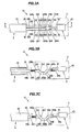
- FIG.3 A is a top view schematically showing a configuration example of the sensor module according to a second embodiment of the invention
- FIG.3 B is a cross-sectional view taken along the line B-B in FIG.3 A
- FIG.3C is a side view schematically showing a configuration example of the sensor module according to the second embodiment of the invention. It is to be noted that FIGs.3 A to 3 C show the molded resin 3 by a two-dot chain line.
- FIGs.3 A to 3 C with regard to the same constituent elements as those explained in the sensor module 1 according to the first embodiment, the same reference signs will be used, and the explanation will be omitted.
- the sensor module 10 includes the cable 2 including the first electric wire 24 including the central conductor 24 a and the insulation 24 b covering the central conductor 24 a, the second electric wire 25 including the central conductor 25 a and the insulation 25 b covering the central conductor 25 a, and the sheath 23 covering the first electric wire 24 and the second electric wire 25; the molded resin 3 molding one end part of the cable 2 in the longitudinal direction; and the sensor 4 connected to the distal end part of the cable 2 in the molded resin 3.
- the sensor module 10 is different in the structure of the first and second electric wires 24, 25 in the molded resin 3, from the structure of the first and second electric wires 21, 22 in the molded resin 3 of the sensor module 1 according to the first embodiment.
- the first electric wire 24 meanders in the molded resin 3 so as to be bent at the first to fourth bent parts 241 to 244.
- the first electric wire 24 includes, other than the first to fourth bent parts 241 to 244, the derivation part 245 derived from the molded resin 3, the first extending part 246a extending from the derivation part 245 to the first bent part 241, the second extending part 246 b extending between the second and third bent parts 242, 243, the third extending part 246 c extending from the fourth bent part 244 to the side of the sensor 4, the first extension part 247 connecting between the first and second bent parts 241, 242 and the second extension part 248 connecting between the third and fourth bent parts 243, 244.
- the first and second extension parts 247, 248 extend in a direction intersected with respect to the derivation direction of the derivation part 245.
- the intersection direction of the first extension part 247 and the intersection direction of the second extension part 248 are symmetrical with respect to the derivation direction of the derivation part 245. Namely, the intersection direction of the first extension part 247 and the intersection direction of the second extension part 248 are intersected with each other.
- the first extension part 247 is located in the molded resin 3 via the first bent part 241 and the first extending part 246 a between the derivation part 245, and the second extension part 248 is located in the molded resin 3 via the first to third bent parts 241 to 243, the first extension part 247, and the first and second extending parts 246 a, 246b between the derivation part 245.
- the first electric wire 24 meanders so as to be bent at the first to fourth bent parts 241 to 244, thereby the first extending part 246 a and the third extending part 246 c are located so as to be aligned along the extending direction.
- the first to the third extending parts 246 a, 246 b, 246 c extend in a direction parallel to each other, thus the third extending part 246 c is located on the extension of the extending direction of the first extending part 246 a.
- the second electric wire 25 meanders so as to be bent at the first to fourth bent parts 251 to 254 in the molded resin 3.
- the second electric wire 25 includes, other than the first to fourth bent parts 251 to 254, the derivation part 255 derived from the molded resin 3, the first extending part 256 a extending from the derivation part 255 to the first bent part 251, the second extending part 256 b extending between the second and third bent parts 252, 253, the third extending part 256 c extending from the fourth bent part 254 to the side of the sensor 4, the first extension part 257 connecting between the first and second bent parts 251, 252 and the second extension part 258 connecting between the third and fourth bent parts 253, 254.
- the first and second extension parts 257, 258 extend in a direction intersected with respect to the derivation direction of the derivation part 255, similarly to the first and second extension parts 247, 248 of the first electric wire 24.
- the intersection direction of the first extension part 257 with respect to the derivation direction of the derivation part 255 is intersected with the intersection direction of the second extension part 258 with respect to the derivation direction of the derivation part 255.
- the first extension part 257 is located in the molded resin 3 via the first bent part 251 and the first extending part 256 a between the derivation part 255
- the second extension part 258 is located in the molded resin 3 via the first to third bent parts 251 to 253, the first extension part 257, and the first and second extending parts 256 a, 256 b between the derivation part 255.
- the third extending part 256 c is located on the extension of the extending direction of the first extending part 256 a.
- first electric wire 24 meanders so as to be bent at four positions of the first to fourth bent parts 241 to 244, and the second electric wire 25 meanders so as to be bent at four positions of the first to fourth bent parts 251 to 254, but the number of the bent part is not particularly limited.
- the first and second electric wires 24, 25 may be respectively bent in an arc shape between the first bent part 241, 251 and the fourth bent part 244, 254.
- the same action and effect as those of (1) and (2) of the first embodiment can be also obtained.
- the first electric wire 24 meanders so as to be bent at the first to fourth bent parts 241 to 244, and the second electric wire 25 meanders so as to be bent at the first to fourth bent parts 251 to 254, thus the sensor module 10 can be prevented from being increased in size as a whole (specifically in the thickness of the molded resin 3 ), while the sensor module 10 makes it possible to include a plurality of the extension parts.
- the cable 2 has been configured to include the first and second electric wires 21, 22 and the sheath 23 covering the first and second electric wires 21, 22, the first and second electric wires 21, 22 including the central conductor 21 a, 22 a and the insulation 21 b, 22 b, but not limited to this, for example, the cable 2 may be a cable comprised of conductors and a sheath without including an insulation or the like, or a cable configured such that not less than 3 electric wires are covered with a sheath. Namely, a cable according to the purpose of use of the sensor module 1, 10 can be applied.
- the sensor module 1, 10 has been explained as one aspect of the cable with the molded resin, but not limited to this, for example, the cable with the molded resin can be applied to connectors and the like by connecting terminals to the distal end of the cable.
Landscapes
- Physics & Mathematics (AREA)
- Spectroscopy & Molecular Physics (AREA)
- Chemical & Material Sciences (AREA)
- Chemical Kinetics & Catalysis (AREA)
- General Physics & Mathematics (AREA)
- Insulated Conductors (AREA)
- Coupling Device And Connection With Printed Circuit (AREA)
- Processing Of Terminals (AREA)
- Cable Accessories (AREA)
- Details Of Connecting Devices For Male And Female Coupling (AREA)
- Transmission And Conversion Of Sensor Element Output (AREA)
Abstract
Description
- The invention relates to a cable with a molded resin that a part of the cable in a longitudinal direction thereof is covered by a molded resin.
- A cable with a molded resin is known in which an electronic component connected to an end part of a cable is covered by a molded resin (see e.g.
JP-A-H09-35820 - The cable disclosed in
JP-A-H09-35820 - The cable is a coaxial cable, and is configured such that internal conducting wires and external conducting wires exposed at the end part are respectively connected to circuit patterns formed on the circuit board. The molded resin integrally covers the connection end part, the circuit board and the electronic components in a state of being covered by the case.
- The cable disclosed in
JP-A-H09-35820 - It is an object of the invention to provide a cable with a molded resin that prevents a tensile force from acting on the end part of the cable even when the tensile force is applied to the cable outside the molded resin.
- According to one embodiment of the invention, a cable with a molded resin comprises:
- a cable comprising an electric wire and a sheath covering the electric wire, the electric wire comprising a central conductor and an insulation covering the central conductor; and
- a molded resin covering a part of the electric wire protruding from the sheath in a longitudinal direction thereof, the molded resin being apart from the sheath,
- wherein the electric wire is bent at not less than one bent part in the molded resin.
- Other embodiments of the invention are defined by the dependent claims.
- According to one embodiment of the invention, a cable with a molded resin can be provided that prevents a tensile force from acting on the end part of the cable even when the tensile force is applied to the cable outside the molded resin.
- The preferred embodiments according to the invention will be explained below referring to the drawings, wherein:
-
FIG.1 is a perspective view schematically showing an appearance of a sensor module according to a first embodiment of the invention; -
FIG.2A is a top view schematically showing a configuration example of the sensor module according to the first embodiment of the invention; -
FIG.2B is a cross-sectional view taken along the line A-A inFIG.2 A; -
FIG.2C is a side view schematically showing a configuration example of the sensor module according to the first embodiment of the invention; -
FIG.3A is a top view schematically showing a configuration example of the sensor module according to a second embodiment of the invention; -
FIG.3B is a cross-sectional view taken along the line B-B inFIG.3 A; and -
FIG.3C is a side view schematically showing a configuration example of the sensor module according to the second embodiment of the invention. - A sensor module according to the first embodiment of the invention is used, for example, as a vehicle mounted sensor or the like mounted on vehicles so as to measure a rotation number of a wheel, a rotation angle of a handle and the like in vehicles. The sensor module is one aspect of the cable with a molded resin of the invention.
-
FIG.1 is a perspective view schematically showing an appearance of a sensor module according to a first embodiment of the invention.FIG.2A is a top view schematically showing a configuration example of the sensor module according to the first embodiment of the invention,FIG.2B is a cross-sectional view taken along the line A-A inFIG.2A, and FIG.2C is a side view schematically showing a configuration example of the sensor module according to the first embodiment of the invention. It is to be noted thatFIGs.2A to 2C show themolded resin 3 by a two-dot chain line. - The
sensor module 1 includes thecable 2, themolded resin 3 molding one end part of thecable 2 in the longitudinal direction and the sensor 4 (shown inFIG.2 ) connected to the dismal end part of thecable 2 in themolded resin 3. - The molded
resin 3 is formed of resin materials such as nylon, polyamide and polybutylene terephthalate (PBT) and, as shown inFIG.1 , has a cylindrical shape extending in the longitudinal direction of thecable 2. The moldedresin 3 may include a glass fiber in order to enhance strength thereof. The moldedresin 3 is not always needed to have a cylindrical shape. For example, themolded resin 3 may have a rectangular cylindrical shape or a bombshell-like shape. - In the embodiment, the
molded resin 3 is configured to mold one end part of the cable in the longitudinal direction and the whole of thesensor 4, but not limited to this, for example, thesensor 4 may be exposed to outside without being covered by themolded resin 3. Namely, themolded resin 3 is not necessarily required to mold the terminals of thecable 2, but themolded resin 3 has only to mold a part of thecable 2 in the longitudinal direction. - The
sensor 4 is, for example, a Hall switch including themeasurement part 40 on which a Hall element or the like configured to detect magnetism is mounted, and a plurality (two in the embodiment) of thelead terminals measurement part 40. It is to be noted that thesensor 4 is not limited to one configured to measure magnetism of a Hall switch, a Hall IC or the like, but thesensor 4 is needed only to be able to measure physical quantity in a state of being covered with themolded resin 3, and thesensor 4 may be one configured to measure temperature and oscillation as a target. - The
cable 2 includes the firstelectric wire 21 including thecentral conductor 21a and theinsulation 21b covering thecentral conductor 21a, the secondelectric wire 22 including thecentral conductor 22a and theinsulation 22b covering thecentral conductor 22a, and thesheath 23 covering the firstelectric wire 21 and the secondelectric wire 22. The end of first and secondelectric wires sheath 23 on the side of the moldedresin 3. In other words, the first and secondelectric wires sheath 23 is covered with themolded resin 3. - As shown in
FIGs.2A and 2B , at the end part of the firstelectric wire 21 in themolded resin 3, thecentral conductor 21a exposed from theinsulation 21b is connected to onelead terminal 41 of thesensor 4, for example, by soldering. Similarly, at the end part of the secondelectric wire 22 in themolded resin 3, thecentral conductor 22a exposed from theinsulation 22b is connected to anotherlead terminal 42 of thesensor 4 - In the embodiment, in order to enhance flexibility in the end part of the sensor module 1 (namely, in order to allow the
molded resin 3 to be easily swinged and bent relative to the cable 2), themolded resin 3 is configured to mold thesensor 4 and a part, which protrudes from thesheath 23, of the first and secondelectric wires sheath 23. Thus, of the first and secondelectric wires sheath 23, the remaining part without being covered by the moldedresin 3 is exposed. - As described above, the
molded resin 3 is disposed apart from thesheath 23 while contacting with the part with a smaller diameter than thesheath 23, of the first and secondelectric wires resin 3 relative to thecable 2. - As described above, the
molded resin 3 is disposed apart from thesheath 23 while contacting with the part with the smaller diameter than thesheath 23, of the first and secondelectric wires cable 2 contacting with the moldedresin 3 is reduced comparing to the case that the moldedresin 3 is also provided on thesheath 23. Thus, when a tensile force is applied to thecable 2, more force can act on the end part of thecable 2 in the moldedresin 3. - In the embodiment, as shown in
FIG.2B , therefore, the firstelectric wire 21 is bent at the first andsecond bent parts molded resin 3. More specifically, the firstelectric wire 21 includes, other than the first andsecond bent parts derivation part 213 derived from themolded resin 3, the first extendingpart 214 extending from thederivation part 213 to thefirst bent part 211, the second extendingpart 215 extending from thesecond bent part 212 to the side of thesensor 4, and theextension part 216 connecting between the first andsecond bent parts - As shown in
FIG.2C , similarly to the firstelectric wire 21, the secondelectric wire 22 is bent at the first andsecond bent parts molded resin 3, and the secondelectric wire 22 includes, other than the first andsecond bent parts derivation part 223, the first and second extendingparts extension part 226. - The first and
second extension parts electric wires molded resin 3 via thefirst bent part part derivation part derivation part extension part derivation part FIGs.2B and 2C is 45 to 90 degrees. - Here, the "derivation direction" means a derived direction of the first and second
electric wires resin 3. For example, the derivation direction is different from a bent direction in a case that thederivation part sensor module 1. - In the embodiment, the first
electric wire 21 is bent at two positions of the first andsecond bent parts electric wire 22 is bent at two positions of the first andsecond bent parts electric wires molded resin 3. - In the
cable 2, when a tensile force T from outside in the derivation direction is applied to the first and secondelectric wires molded resin 3, a part of the tensile force transmitted is dispersed in theextension part extension part - The first and second
electric wires resin 3. Thereby, the moldedresin 3 can penetrate between the first and secondelectric wires electric wires electric wires resin 3 can be further increased. - According to the first embodiment explained above, the following action and effect can be obtained.
- (1) The cable 2 (the first and second
electric wires 21, 22) is bent at the firstbent part bent part resin 3, thus even if a tensile force is applied to thecable 2 from outside in the derivation direction, the tensile force acting on the side of the dismal end part of thecable 2 is reduced via the firstbent part bent part central conductor 21a of the firstelectric wire 21 and thelead terminal 41 of thesensor 4, and the connection part between thecentral conductor 22a of the secondelectric wire 22 and thelead terminal 42 of thesensor 4 is reduced, while the moldedresin 3 can be easily swinged and bent relative to thecable 2. - (2) The
extension part derivation part resin 3 via the firstbent part derivation part cable 2 from outside in the derivation direction is received by the whole of theextension part central conductor 21a of the firstelectric wire 21 and thelead terminal 41 of thesensor 4, and the connection part between thecentral conductor 22a of the secondelectric wire 22 and thelead terminal 42 of thesensor 4 is further reduced. - Next, the second embodiment according to the invention will be explained referring to
FIG.3 . -
FIG.3A is a top view schematically showing a configuration example of the sensor module according to a second embodiment of the invention,FIG.3B is a cross-sectional view taken along the line B-B inFIG.3A and FIG.3C is a side view schematically showing a configuration example of the sensor module according to the second embodiment of the invention. It is to be noted thatFIGs.3A to 3C show the moldedresin 3 by a two-dot chain line. - In
FIGs.3A to 3C , with regard to the same constituent elements as those explained in thesensor module 1 according to the first embodiment, the same reference signs will be used, and the explanation will be omitted. - The
sensor module 10 according to the embodiment includes thecable 2 including the firstelectric wire 24 including thecentral conductor 24a and theinsulation 24b covering thecentral conductor 24a, the secondelectric wire 25 including thecentral conductor 25a and theinsulation 25b covering thecentral conductor 25a, and thesheath 23 covering the firstelectric wire 24 and the secondelectric wire 25; the moldedresin 3 molding one end part of thecable 2 in the longitudinal direction; and thesensor 4 connected to the distal end part of thecable 2 in the moldedresin 3. - The
sensor module 10 is different in the structure of the first and secondelectric wires resin 3, from the structure of the first and secondelectric wires resin 3 of thesensor module 1 according to the first embodiment. - As shown in
FIG3B , the firstelectric wire 24 meanders in the moldedresin 3 so as to be bent at the first to fourthbent parts 241 to 244. - More specifically, the first
electric wire 24 includes, other than the first to fourthbent parts 241 to 244, thederivation part 245 derived from the moldedresin 3, the first extendingpart 246a extending from thederivation part 245 to the firstbent part 241, the second extendingpart 246b extending between the second and thirdbent parts part 246c extending from the fourthbent part 244 to the side of thesensor 4, thefirst extension part 247 connecting between the first and secondbent parts second extension part 248 connecting between the third and fourthbent parts - The first and
second extension parts derivation part 245. In the embodiment, the intersection direction of thefirst extension part 247 and the intersection direction of thesecond extension part 248 are symmetrical with respect to the derivation direction of thederivation part 245. Namely, the intersection direction of thefirst extension part 247 and the intersection direction of thesecond extension part 248 are intersected with each other. - The
first extension part 247 is located in the moldedresin 3 via the firstbent part 241 and the first extendingpart 246a between thederivation part 245, and thesecond extension part 248 is located in the moldedresin 3 via the first to thirdbent parts 241 to 243, thefirst extension part 247, and the first and second extendingparts derivation part 245. - As described above, the first
electric wire 24 meanders so as to be bent at the first to fourthbent parts 241 to 244, thereby the first extendingpart 246a and the third extendingpart 246c are located so as to be aligned along the extending direction. In the embodiment, the first to the third extendingparts part 246c is located on the extension of the extending direction of the first extendingpart 246a. - As shown in
FIG.3C , similarly to the firstelectric wire 24, the secondelectric wire 25 meanders so as to be bent at the first to fourthbent parts 251 to 254 in the moldedresin 3. - More specifically, the second
electric wire 25 includes, other than the first to fourthbent parts 251 to 254, thederivation part 255 derived from the moldedresin 3, the first extendingpart 256a extending from thederivation part 255 to the firstbent part 251, the second extendingpart 256b extending between the second and thirdbent parts part 256c extending from the fourthbent part 254 to the side of thesensor 4, thefirst extension part 257 connecting between the first and secondbent parts second extension part 258 connecting between the third and fourthbent parts - The first and
second extension parts derivation part 255, similarly to the first andsecond extension parts electric wire 24. The intersection direction of thefirst extension part 257 with respect to the derivation direction of thederivation part 255 is intersected with the intersection direction of thesecond extension part 258 with respect to the derivation direction of thederivation part 255. - The
first extension part 257 is located in the moldedresin 3 via the firstbent part 251 and the first extendingpart 256a between thederivation part 255, and thesecond extension part 258 is located in the moldedresin 3 via the first to thirdbent parts 251 to 253, thefirst extension part 257, and the first and second extendingparts derivation part 255. In addition, the third extendingpart 256c is located on the extension of the extending direction of the first extendingpart 256a. - In the embodiment, the first
electric wire 24 meanders so as to be bent at four positions of the first to fourthbent parts 241 to 244, and the secondelectric wire 25 meanders so as to be bent at four positions of the first to fourthbent parts 251 to 254, but the number of the bent part is not particularly limited. The first and secondelectric wires bent part bent part - In the
cable 2, when a tensile force T from outside in the derivation direction is applied to the first and secondelectric wires resin 3, a part of the tensile force transmitted is dispersed in thefirst extension part second extension part - According to the second embodiment explained above, the same action and effect as those of (1) and (2) of the first embodiment can be also obtained. In addition, the first
electric wire 24 meanders so as to be bent at the first to fourthbent parts 241 to 244, and the secondelectric wire 25 meanders so as to be bent at the first to fourthbent parts 251 to 254, thus thesensor module 10 can be prevented from being increased in size as a whole (specifically in the thickness of the molded resin 3), while thesensor module 10 makes it possible to include a plurality of the extension parts. - Next, technical ideas grasped from the above-mentioned embodiments will be described referring to reference signs and the like in the embodiments. It is to be noted that, however, each of the reference signs and the like in the following description does not limit the constituent elements in the scope of claims to members and the like shown in the embodiments specifically.
- [1] The cable with a molded resin (the
sensor module 1, 10), including the cable (2) including at least one electric wire (21, 22 / 24, 25) and a sheath (23) covering the electric wire (21, 22 / 24, 25), the electric wire (21, 22 / 24, 25) comprising the central conductor (21a, 22a /24a, 25a) and the insulation (21b, 22b /24b, 25b) covering the central conductor (21a, 22a /24a, 25a), and the molded resin (3) covering a part of the electric wire (21, 22 / 24, 25) in the longitudinal direction and disposed apart from the sheath (23), the electric wire (21, 22 / 24, 25) protruding from the sheath (23), wherein the electric wire (21, 22 / 24, 25) is bent at not less than one bent part (the firstbent part bent part bent parts 241 to 244, 251 to 254) in the molded resin (3). - [2] The cable with a molded resin (the
sensor module 1, 10) according to [1], wherein the electric wire (21, 22 / 24, 25) comprises the derivation part (213, 223 / 245, 255) derived from the molded resin (3) and the extension part (216, 226 / thefirst extension part second extension part 248, 258) extending in a direction intersected with respect to the derivation direction of the derivation part (213, 223 / 245, 255), wherein the extension part (216, 226 / thefirst extension part second extension part 248, 258) is located in the molded resin (3) via the bent part (the firstbent part - [3] The cable with a molded resin (the
sensor module 1, 10) according to [2], wherein the extension part (216, 226 / thefirst extension part second extension part 248, 258) extends in a direction intersected at the angle of 45 to 90 degrees with respect to the derivation direction. - [4] The cable with a molded resin (the sensor module 10) according to [1], wherein the electric wire (21, 22 / 24, 25) meanders in the molded resin (3) so as to be bent at a plurality of the bent parts (the first to fourth
bent parts 241 to 244, 251 to 254). - [5] The cable with a molded resin (the
sensor module 1, 10) according to [1], further comprising the sensor (4) connected to an end part of the electric wire (21, 22 / 24, 25) in the molded resin (3). - [6] The cable with a molded resin (the
sensor module 1, 10) according to [5], wherein the sensor (4) comprises the measurement part (40) with the element (a Hall element or the like) to detect magnetism mounted thereon and the lead terminal (41, 42) disposed at the measurement part (40) and wherein the central conductor (21a, 22a /24a, 25a) is connected to the lead terminal. - [7] The cable with a molded resin (the
sensor module 1, 10) according to [1], wherein the molded resin (3) comprises at least one of nylon, polyamide and polybutylene terephthalate (PBT). - [8] The cable with a molded resin (the
sensor module 1, 10) according to [7], wherein the molded resin (3) further comprises a glass fiber. - [9] The cable with a molded resin (the
sensor module 1, 10) according to [1], wherein the cable (2) comprises a plurality of the electric wires (21, 22 / 24, 25), and wherein the plurality of the electric wires (21, 22 / 24, 25) are arranged apart from each other in the molded resin (3). - Although the invention has been described with respect to the specific embodiments for complete and clear disclosure, the appended claims are not to be thus limited but are to be construed as embodying all modifications and alternative constructions that may occur to one skilled in the art which fairly fall within the basic teaching herein set forth.
- For example, in the above-mentioned embodiments, the
cable 2 has been configured to include the first and secondelectric wires sheath 23 covering the first and secondelectric wires electric wires central conductor insulation cable 2 may be a cable comprised of conductors and a sheath without including an insulation or the like, or a cable configured such that not less than 3 electric wires are covered with a sheath. Namely, a cable according to the purpose of use of thesensor module - In addition, in the above-mentioned embodiments, the
sensor module
Claims (9)
- A cable with a molded resin (1; 10), comprising:a cable (2) comprising an electric wire (21, 22; 24, 25) and a sheath (23) covering the electric wire, the electric wire comprising a central conductor (21a, 22a; 24a, 25a) and an insulation (21b, 22b; 24b, 25b) covering the central conductor; anda molded resin (3) covering a part of the electric wire protruding from the sheath (23) in a longitudinal direction thereof, the molded resin being apart from the sheath,wherein the electric wire (21, 22; 24, 25) is bent at not less than one bent part (211, 221; 212, 222; 241-244; 251-254) in the molded resin.
- The cable (1; 10) according to claim 1, wherein the electric wire comprises a derivation part (213, 223; 245, 255) derived from the molded resin (3) and an extension part (216, 226; 247, 257; 248, 258) extending in a direction intersected with a derivation direction of the derivation part, and
wherein the extension part is disposed in the molded resin such that the bent part falls between the derivation part and the extension part. - The cable (1; 10) according to claim 2, wherein the extension part (216, 226; 247, 257; 248, 258) extends in a direction intersected at an angle of 45 to 90 degrees with the derivation direction.
- The cable (1; 10) according to any one of claims 1 to 3, wherein the electric wire (21, 22; 24, 25) meanders in the molded resin (3) so as to be bent at a plurality of ones of the bent parts (211, 221; 212, 222; 241-244; 251-254).
- The cable (1; 10) according to any one of claims 1 to 4, further comprising a sensor (4) connected to an end part of the electric wire (21, 22; 24, 25) in the molded resin (3).
- The cable (1; 10) according to claim 5, wherein the sensor (4) comprises a measurement part (40) with an element to detect magnetism mounted thereon and a lead terminal (41, 42) disposed at the measurement part (40), and
wherein the central conductor (21a, 22a; 24a, 25a) is connected to the lead terminal (41, 42). - The cable (1; 10) according to any one of claims 1 to 6, wherein the molded resin (3) comprises one of nylon, polyamide and polybutylene terephthalate (PBT).
- The cable (1; 10) according to any one of claims 1 to 7, wherein the molded resin (3) comprises a glass fiber.
- The cable (1; 10) according to any one of claims 1 to 8, wherein the cable (2) comprises a plurality of ones of the electric wire (21, 22; 24, 25), and
wherein the plurality of the electric wires are arranged apart from each other in the molded resin (3).
Applications Claiming Priority (1)
| Application Number | Priority Date | Filing Date | Title |
|---|---|---|---|
| JP2014124649A JP6403088B2 (en) | 2014-06-17 | 2014-06-17 | Molded resin cable |
Publications (2)
| Publication Number | Publication Date |
|---|---|
| EP2958196A1 true EP2958196A1 (en) | 2015-12-23 |
| EP2958196B1 EP2958196B1 (en) | 2020-12-09 |
Family
ID=53396294
Family Applications (1)
| Application Number | Title | Priority Date | Filing Date |
|---|---|---|---|
| EP15171050.6A Active EP2958196B1 (en) | 2014-06-17 | 2015-06-08 | Cable with molded resin |
Country Status (4)
| Country | Link |
|---|---|
| US (1) | US9640302B2 (en) |
| EP (1) | EP2958196B1 (en) |
| JP (1) | JP6403088B2 (en) |
| CN (1) | CN204668598U (en) |
Families Citing this family (5)
| Publication number | Priority date | Publication date | Assignee | Title |
|---|---|---|---|---|
| JP6281461B2 (en) * | 2014-09-30 | 2018-02-21 | 日立金属株式会社 | Manufacturing method of cable with resin mold |
| JP6720495B2 (en) * | 2015-10-07 | 2020-07-08 | 日立金属株式会社 | Molded electric wire and molded cable, electric wire for molded electric wire and cable for molded cable |
| JP6838306B2 (en) * | 2016-07-08 | 2021-03-03 | 日立金属株式会社 | In-vehicle detection device |
| DE102017210979B4 (en) * | 2017-06-28 | 2024-02-15 | Vitesco Technologies Germany Gmbh | Method for producing an electrical component and electrical component |
| JP7363548B2 (en) * | 2020-02-07 | 2023-10-18 | 株式会社プロテリアル | Cable with sensor and its manufacturing method |
Citations (4)
| Publication number | Priority date | Publication date | Assignee | Title |
|---|---|---|---|---|
| JPH0935820A (en) | 1995-07-24 | 1997-02-07 | Taiyo Yuden Co Ltd | Connector with built-in electronic components |
| US20010010982A1 (en) * | 1999-02-25 | 2001-08-02 | Masaharu Sakaguchi | Wire module and method of producing same |
| US20070187869A1 (en) * | 2006-02-15 | 2007-08-16 | Siemens Vdo Automotive Corporation | Single mold active speed sensor |
| US20130203284A1 (en) * | 2010-03-09 | 2013-08-08 | Bontaz Centre | Device for producing a sealed electrical connection through a wall |
Family Cites Families (9)
| Publication number | Priority date | Publication date | Assignee | Title |
|---|---|---|---|---|
| JPH0335669U (en) * | 1989-08-14 | 1991-04-08 | ||
| JPH04141607A (en) * | 1990-10-02 | 1992-05-15 | Sumitomo Electric Ind Ltd | communication cable |
| US5074808A (en) * | 1991-02-06 | 1991-12-24 | Amp Incorporated | Molded strain relief in back shell |
| JP4768586B2 (en) * | 2006-11-28 | 2011-09-07 | 住電エレクトロニクス株式会社 | Sensor with signal cable and method of manufacturing the sensor |
| JP5668705B2 (en) * | 2011-06-15 | 2015-02-12 | 日立金属株式会社 | Cross-linked resin composition, and electric wire / cable and molded electric wire coated with cross-linked resin composition |
| JP2013026052A (en) * | 2011-07-22 | 2013-02-04 | Hitachi Cable Ltd | Resin mold structure with cable |
| EP2645490B1 (en) * | 2011-11-09 | 2018-01-03 | Fuji Electric Wire Industries CO., LTD. | Electrical wire wiring structure for plug |
| JP5573826B2 (en) * | 2011-12-16 | 2014-08-20 | 株式会社デンソー | Rotation detecting device and manufacturing method thereof |
| JP6015008B2 (en) * | 2012-01-23 | 2016-10-26 | アイシン精機株式会社 | Sensor |
-
2014
- 2014-06-17 JP JP2014124649A patent/JP6403088B2/en active Active
-
2015
- 2015-06-05 US US14/732,532 patent/US9640302B2/en not_active Expired - Fee Related
- 2015-06-05 CN CN201520382287.9U patent/CN204668598U/en not_active Expired - Lifetime
- 2015-06-08 EP EP15171050.6A patent/EP2958196B1/en active Active
Patent Citations (4)
| Publication number | Priority date | Publication date | Assignee | Title |
|---|---|---|---|---|
| JPH0935820A (en) | 1995-07-24 | 1997-02-07 | Taiyo Yuden Co Ltd | Connector with built-in electronic components |
| US20010010982A1 (en) * | 1999-02-25 | 2001-08-02 | Masaharu Sakaguchi | Wire module and method of producing same |
| US20070187869A1 (en) * | 2006-02-15 | 2007-08-16 | Siemens Vdo Automotive Corporation | Single mold active speed sensor |
| US20130203284A1 (en) * | 2010-03-09 | 2013-08-08 | Bontaz Centre | Device for producing a sealed electrical connection through a wall |
Also Published As
| Publication number | Publication date |
|---|---|
| CN204668598U (en) | 2015-09-23 |
| JP2016004694A (en) | 2016-01-12 |
| US9640302B2 (en) | 2017-05-02 |
| JP6403088B2 (en) | 2018-10-10 |
| EP2958196B1 (en) | 2020-12-09 |
| US20150364231A1 (en) | 2015-12-17 |
Similar Documents
| Publication | Publication Date | Title |
|---|---|---|
| US12080910B2 (en) | Wiring material and battery module | |
| US10381752B2 (en) | Module connector | |
| US9640302B2 (en) | Cable with molded resin | |
| US7722362B2 (en) | Sensor adaptor circuit housing incapsulating connection of an input connector with a wire | |
| US8851935B2 (en) | Electrical wire harness connector | |
| US20160233622A1 (en) | Electrical connector part having a resistance coding | |
| US9472914B2 (en) | Rotary connector having a positive temperature coefficient device | |
| US9124026B2 (en) | Cable assembly, electronic circuit module, and imaging apparatus | |
| US9362679B2 (en) | Insulation body of a plug-in connector | |
| US20110287659A1 (en) | Electric multiple distributor | |
| CN102735280B (en) | Sensor assembly and the method for manufacturing sensor assembly | |
| CN104040793B (en) | Wire with terminal | |
| US20150207258A1 (en) | Connecting cable | |
| US20090298327A1 (en) | Connecting module | |
| US10483703B2 (en) | Connector | |
| US6951475B2 (en) | Cable strain relief device | |
| US20180123300A1 (en) | Electronic controller | |
| US12160075B2 (en) | Rotary connector device and flat cable assembly for rotary connector device | |
| US5700152A (en) | Electrical terminal apparatus | |
| US20160163428A1 (en) | Apparatus to form a radiused bend in a flat flexible cable | |
| JP6180388B2 (en) | Flat cable | |
| KR101948103B1 (en) | Elctronic control device using bendable pcb | |
| KR101353014B1 (en) | Terminal member for control unit test apparatus and control unit test apparatus comprising thereof | |
| KR20110072648A (en) | Cables and Cable Connectors | |
| US10038257B2 (en) | Multi-core cable and multi-core cable with substrate |
Legal Events
| Date | Code | Title | Description |
|---|---|---|---|
| PUAI | Public reference made under article 153(3) epc to a published international application that has entered the european phase |
Free format text: ORIGINAL CODE: 0009012 |
|
| AK | Designated contracting states |
Kind code of ref document: A1 Designated state(s): AL AT BE BG CH CY CZ DE DK EE ES FI FR GB GR HR HU IE IS IT LI LT LU LV MC MK MT NL NO PL PT RO RS SE SI SK SM TR |
|
| AX | Request for extension of the european patent |
Extension state: BA ME |
|
| 17P | Request for examination filed |
Effective date: 20160615 |
|
| RBV | Designated contracting states (corrected) |
Designated state(s): AL AT BE BG CH CY CZ DE DK EE ES FI FR GB GR HR HU IE IS IT LI LT LU LV MC MK MT NL NO PL PT RO RS SE SI SK SM TR |
|
| STAA | Information on the status of an ep patent application or granted ep patent |
Free format text: STATUS: EXAMINATION IS IN PROGRESS |
|
| 17Q | First examination report despatched |
Effective date: 20170519 |
|
| RIC1 | Information provided on ipc code assigned before grant |
Ipc: H01B 7/24 20060101ALI20180917BHEP Ipc: H01B 3/47 20060101ALI20180917BHEP Ipc: H01B 3/42 20060101ALI20180917BHEP Ipc: H01B 3/30 20060101ALI20180917BHEP Ipc: H01R 13/58 20060101AFI20180917BHEP Ipc: G01D 11/24 20060101ALI20180917BHEP |
|
| GRAP | Despatch of communication of intention to grant a patent |
Free format text: ORIGINAL CODE: EPIDOSNIGR1 |
|
| STAA | Information on the status of an ep patent application or granted ep patent |
Free format text: STATUS: GRANT OF PATENT IS INTENDED |
|
| INTG | Intention to grant announced |
Effective date: 20200724 |
|
| GRAS | Grant fee paid |
Free format text: ORIGINAL CODE: EPIDOSNIGR3 |
|
| GRAA | (expected) grant |
Free format text: ORIGINAL CODE: 0009210 |
|
| STAA | Information on the status of an ep patent application or granted ep patent |
Free format text: STATUS: THE PATENT HAS BEEN GRANTED |
|
| AK | Designated contracting states |
Kind code of ref document: B1 Designated state(s): AL AT BE BG CH CY CZ DE DK EE ES FI FR GB GR HR HU IE IS IT LI LT LU LV MC MK MT NL NO PL PT RO RS SE SI SK SM TR |
|
| REG | Reference to a national code |
Ref country code: GB Ref legal event code: FG4D |
|
| REG | Reference to a national code |
Ref country code: AT Ref legal event code: REF Ref document number: 1344349 Country of ref document: AT Kind code of ref document: T Effective date: 20201215 Ref country code: CH Ref legal event code: EP |
|
| REG | Reference to a national code |
Ref country code: DE Ref legal event code: R096 Ref document number: 602015063140 Country of ref document: DE |
|
| REG | Reference to a national code |
Ref country code: IE Ref legal event code: FG4D |
|
| PG25 | Lapsed in a contracting state [announced via postgrant information from national office to epo] |
Ref country code: GR Free format text: LAPSE BECAUSE OF FAILURE TO SUBMIT A TRANSLATION OF THE DESCRIPTION OR TO PAY THE FEE WITHIN THE PRESCRIBED TIME-LIMIT Effective date: 20210310 Ref country code: NO Free format text: LAPSE BECAUSE OF FAILURE TO SUBMIT A TRANSLATION OF THE DESCRIPTION OR TO PAY THE FEE WITHIN THE PRESCRIBED TIME-LIMIT Effective date: 20210309 Ref country code: RS Free format text: LAPSE BECAUSE OF FAILURE TO SUBMIT A TRANSLATION OF THE DESCRIPTION OR TO PAY THE FEE WITHIN THE PRESCRIBED TIME-LIMIT Effective date: 20201209 Ref country code: FI Free format text: LAPSE BECAUSE OF FAILURE TO SUBMIT A TRANSLATION OF THE DESCRIPTION OR TO PAY THE FEE WITHIN THE PRESCRIBED TIME-LIMIT Effective date: 20201209 |
|
| REG | Reference to a national code |
Ref country code: AT Ref legal event code: MK05 Ref document number: 1344349 Country of ref document: AT Kind code of ref document: T Effective date: 20201209 |
|
| PG25 | Lapsed in a contracting state [announced via postgrant information from national office to epo] |
Ref country code: SE Free format text: LAPSE BECAUSE OF FAILURE TO SUBMIT A TRANSLATION OF THE DESCRIPTION OR TO PAY THE FEE WITHIN THE PRESCRIBED TIME-LIMIT Effective date: 20201209 Ref country code: LV Free format text: LAPSE BECAUSE OF FAILURE TO SUBMIT A TRANSLATION OF THE DESCRIPTION OR TO PAY THE FEE WITHIN THE PRESCRIBED TIME-LIMIT Effective date: 20201209 Ref country code: BG Free format text: LAPSE BECAUSE OF FAILURE TO SUBMIT A TRANSLATION OF THE DESCRIPTION OR TO PAY THE FEE WITHIN THE PRESCRIBED TIME-LIMIT Effective date: 20210309 |
|
| REG | Reference to a national code |
Ref country code: NL Ref legal event code: MP Effective date: 20201209 |
|
| PG25 | Lapsed in a contracting state [announced via postgrant information from national office to epo] |
Ref country code: NL Free format text: LAPSE BECAUSE OF FAILURE TO SUBMIT A TRANSLATION OF THE DESCRIPTION OR TO PAY THE FEE WITHIN THE PRESCRIBED TIME-LIMIT Effective date: 20201209 Ref country code: HR Free format text: LAPSE BECAUSE OF FAILURE TO SUBMIT A TRANSLATION OF THE DESCRIPTION OR TO PAY THE FEE WITHIN THE PRESCRIBED TIME-LIMIT Effective date: 20201209 |
|
| REG | Reference to a national code |
Ref country code: LT Ref legal event code: MG9D |
|
| PG25 | Lapsed in a contracting state [announced via postgrant information from national office to epo] |
Ref country code: SK Free format text: LAPSE BECAUSE OF FAILURE TO SUBMIT A TRANSLATION OF THE DESCRIPTION OR TO PAY THE FEE WITHIN THE PRESCRIBED TIME-LIMIT Effective date: 20201209 Ref country code: RO Free format text: LAPSE BECAUSE OF FAILURE TO SUBMIT A TRANSLATION OF THE DESCRIPTION OR TO PAY THE FEE WITHIN THE PRESCRIBED TIME-LIMIT Effective date: 20201209 Ref country code: PT Free format text: LAPSE BECAUSE OF FAILURE TO SUBMIT A TRANSLATION OF THE DESCRIPTION OR TO PAY THE FEE WITHIN THE PRESCRIBED TIME-LIMIT Effective date: 20210409 Ref country code: LT Free format text: LAPSE BECAUSE OF FAILURE TO SUBMIT A TRANSLATION OF THE DESCRIPTION OR TO PAY THE FEE WITHIN THE PRESCRIBED TIME-LIMIT Effective date: 20201209 Ref country code: EE Free format text: LAPSE BECAUSE OF FAILURE TO SUBMIT A TRANSLATION OF THE DESCRIPTION OR TO PAY THE FEE WITHIN THE PRESCRIBED TIME-LIMIT Effective date: 20201209 Ref country code: CZ Free format text: LAPSE BECAUSE OF FAILURE TO SUBMIT A TRANSLATION OF THE DESCRIPTION OR TO PAY THE FEE WITHIN THE PRESCRIBED TIME-LIMIT Effective date: 20201209 Ref country code: SM Free format text: LAPSE BECAUSE OF FAILURE TO SUBMIT A TRANSLATION OF THE DESCRIPTION OR TO PAY THE FEE WITHIN THE PRESCRIBED TIME-LIMIT Effective date: 20201209 |
|
| PG25 | Lapsed in a contracting state [announced via postgrant information from national office to epo] |
Ref country code: PL Free format text: LAPSE BECAUSE OF FAILURE TO SUBMIT A TRANSLATION OF THE DESCRIPTION OR TO PAY THE FEE WITHIN THE PRESCRIBED TIME-LIMIT Effective date: 20201209 Ref country code: AT Free format text: LAPSE BECAUSE OF FAILURE TO SUBMIT A TRANSLATION OF THE DESCRIPTION OR TO PAY THE FEE WITHIN THE PRESCRIBED TIME-LIMIT Effective date: 20201209 |
|
| REG | Reference to a national code |
Ref country code: DE Ref legal event code: R097 Ref document number: 602015063140 Country of ref document: DE |
|
| PG25 | Lapsed in a contracting state [announced via postgrant information from national office to epo] |
Ref country code: IS Free format text: LAPSE BECAUSE OF FAILURE TO SUBMIT A TRANSLATION OF THE DESCRIPTION OR TO PAY THE FEE WITHIN THE PRESCRIBED TIME-LIMIT Effective date: 20210409 |
|
| PLBE | No opposition filed within time limit |
Free format text: ORIGINAL CODE: 0009261 |
|
| STAA | Information on the status of an ep patent application or granted ep patent |
Free format text: STATUS: NO OPPOSITION FILED WITHIN TIME LIMIT |
|
| PG25 | Lapsed in a contracting state [announced via postgrant information from national office to epo] |
Ref country code: AL Free format text: LAPSE BECAUSE OF FAILURE TO SUBMIT A TRANSLATION OF THE DESCRIPTION OR TO PAY THE FEE WITHIN THE PRESCRIBED TIME-LIMIT Effective date: 20201209 Ref country code: IT Free format text: LAPSE BECAUSE OF FAILURE TO SUBMIT A TRANSLATION OF THE DESCRIPTION OR TO PAY THE FEE WITHIN THE PRESCRIBED TIME-LIMIT Effective date: 20201209 |
|
| 26N | No opposition filed |
Effective date: 20210910 |
|
| PG25 | Lapsed in a contracting state [announced via postgrant information from national office to epo] |
Ref country code: SI Free format text: LAPSE BECAUSE OF FAILURE TO SUBMIT A TRANSLATION OF THE DESCRIPTION OR TO PAY THE FEE WITHIN THE PRESCRIBED TIME-LIMIT Effective date: 20201209 Ref country code: ES Free format text: LAPSE BECAUSE OF FAILURE TO SUBMIT A TRANSLATION OF THE DESCRIPTION OR TO PAY THE FEE WITHIN THE PRESCRIBED TIME-LIMIT Effective date: 20201209 Ref country code: DK Free format text: LAPSE BECAUSE OF FAILURE TO SUBMIT A TRANSLATION OF THE DESCRIPTION OR TO PAY THE FEE WITHIN THE PRESCRIBED TIME-LIMIT Effective date: 20201209 |
|
| REG | Reference to a national code |
Ref country code: DE Ref legal event code: R119 Ref document number: 602015063140 Country of ref document: DE |
|
| PG25 | Lapsed in a contracting state [announced via postgrant information from national office to epo] |
Ref country code: MC Free format text: LAPSE BECAUSE OF FAILURE TO SUBMIT A TRANSLATION OF THE DESCRIPTION OR TO PAY THE FEE WITHIN THE PRESCRIBED TIME-LIMIT Effective date: 20201209 |
|
| REG | Reference to a national code |
Ref country code: CH Ref legal event code: PL |
|
| GBPC | Gb: european patent ceased through non-payment of renewal fee |
Effective date: 20210608 |
|
| REG | Reference to a national code |
Ref country code: BE Ref legal event code: MM Effective date: 20210630 |
|
| PG25 | Lapsed in a contracting state [announced via postgrant information from national office to epo] |
Ref country code: LU Free format text: LAPSE BECAUSE OF NON-PAYMENT OF DUE FEES Effective date: 20210608 |
|
| PG25 | Lapsed in a contracting state [announced via postgrant information from national office to epo] |
Ref country code: LI Free format text: LAPSE BECAUSE OF NON-PAYMENT OF DUE FEES Effective date: 20210630 Ref country code: IE Free format text: LAPSE BECAUSE OF NON-PAYMENT OF DUE FEES Effective date: 20210608 Ref country code: GB Free format text: LAPSE BECAUSE OF NON-PAYMENT OF DUE FEES Effective date: 20210608 Ref country code: DE Free format text: LAPSE BECAUSE OF NON-PAYMENT OF DUE FEES Effective date: 20220101 Ref country code: CH Free format text: LAPSE BECAUSE OF NON-PAYMENT OF DUE FEES Effective date: 20210630 |
|
| PG25 | Lapsed in a contracting state [announced via postgrant information from national office to epo] |
Ref country code: IS Free format text: LAPSE BECAUSE OF FAILURE TO SUBMIT A TRANSLATION OF THE DESCRIPTION OR TO PAY THE FEE WITHIN THE PRESCRIBED TIME-LIMIT Effective date: 20210409 |
|
| PG25 | Lapsed in a contracting state [announced via postgrant information from national office to epo] |
Ref country code: BE Free format text: LAPSE BECAUSE OF NON-PAYMENT OF DUE FEES Effective date: 20210630 |
|
| PG25 | Lapsed in a contracting state [announced via postgrant information from national office to epo] |
Ref country code: HU Free format text: LAPSE BECAUSE OF FAILURE TO SUBMIT A TRANSLATION OF THE DESCRIPTION OR TO PAY THE FEE WITHIN THE PRESCRIBED TIME-LIMIT; INVALID AB INITIO Effective date: 20150608 |
|
| PG25 | Lapsed in a contracting state [announced via postgrant information from national office to epo] |
Ref country code: CY Free format text: LAPSE BECAUSE OF FAILURE TO SUBMIT A TRANSLATION OF THE DESCRIPTION OR TO PAY THE FEE WITHIN THE PRESCRIBED TIME-LIMIT Effective date: 20201209 |
|
| PG25 | Lapsed in a contracting state [announced via postgrant information from national office to epo] |
Ref country code: MK Free format text: LAPSE BECAUSE OF FAILURE TO SUBMIT A TRANSLATION OF THE DESCRIPTION OR TO PAY THE FEE WITHIN THE PRESCRIBED TIME-LIMIT Effective date: 20201209 |
|
| PG25 | Lapsed in a contracting state [announced via postgrant information from national office to epo] |
Ref country code: TR Free format text: LAPSE BECAUSE OF FAILURE TO SUBMIT A TRANSLATION OF THE DESCRIPTION OR TO PAY THE FEE WITHIN THE PRESCRIBED TIME-LIMIT Effective date: 20201209 |
|
| PG25 | Lapsed in a contracting state [announced via postgrant information from national office to epo] |
Ref country code: MT Free format text: LAPSE BECAUSE OF FAILURE TO SUBMIT A TRANSLATION OF THE DESCRIPTION OR TO PAY THE FEE WITHIN THE PRESCRIBED TIME-LIMIT Effective date: 20201209 |
|
| PGFP | Annual fee paid to national office [announced via postgrant information from national office to epo] |
Ref country code: FR Payment date: 20260511 Year of fee payment: 12 |