EP2957852A1 - Flow deflectors - Google Patents
Flow deflectors Download PDFInfo
- Publication number
- EP2957852A1 EP2957852A1 EP14382234.4A EP14382234A EP2957852A1 EP 2957852 A1 EP2957852 A1 EP 2957852A1 EP 14382234 A EP14382234 A EP 14382234A EP 2957852 A1 EP2957852 A1 EP 2957852A1
- Authority
- EP
- European Patent Office
- Prior art keywords
- tubes
- bundle
- shell
- tubular body
- flow deflector
- Prior art date
- Legal status (The legal status is an assumption and is not a legal conclusion. Google has not performed a legal analysis and makes no representation as to the accuracy of the status listed.)
- Granted
Links
Images

Classifications
-
- F—MECHANICAL ENGINEERING; LIGHTING; HEATING; WEAPONS; BLASTING
- F28—HEAT EXCHANGE IN GENERAL
- F28F—DETAILS OF HEAT-EXCHANGE AND HEAT-TRANSFER APPARATUS, OF GENERAL APPLICATION
- F28F9/00—Casings; Header boxes; Auxiliary supports for elements; Auxiliary members within casings
- F28F9/005—Other auxiliary members within casings, e.g. internal filling means or sealing means
-
- F—MECHANICAL ENGINEERING; LIGHTING; HEATING; WEAPONS; BLASTING
- F28—HEAT EXCHANGE IN GENERAL
- F28F—DETAILS OF HEAT-EXCHANGE AND HEAT-TRANSFER APPARATUS, OF GENERAL APPLICATION
- F28F13/00—Arrangements for modifying heat-transfer, e.g. increasing, decreasing
- F28F13/06—Arrangements for modifying heat-transfer, e.g. increasing, decreasing by affecting the pattern of flow of the heat-exchange media
- F28F13/08—Arrangements for modifying heat-transfer, e.g. increasing, decreasing by affecting the pattern of flow of the heat-exchange media by varying the cross-section of the flow channels
-
- F—MECHANICAL ENGINEERING; LIGHTING; HEATING; WEAPONS; BLASTING
- F02—COMBUSTION ENGINES; HOT-GAS OR COMBUSTION-PRODUCT ENGINE PLANTS
- F02M—SUPPLYING COMBUSTION ENGINES IN GENERAL WITH COMBUSTIBLE MIXTURES OR CONSTITUENTS THEREOF
- F02M26/00—Engine-pertinent apparatus for adding exhaust gases to combustion-air, main fuel or fuel-air mixture, e.g. by exhaust gas recirculation [EGR] systems
- F02M26/13—Arrangement or layout of EGR passages, e.g. in relation to specific engine parts or for incorporation of accessories
- F02M26/22—Arrangement or layout of EGR passages, e.g. in relation to specific engine parts or for incorporation of accessories with coolers in the recirculation passage
- F02M26/29—Constructional details of the coolers, e.g. pipes, plates, ribs, insulation or materials
- F02M26/32—Liquid-cooled heat exchangers
-
- F—MECHANICAL ENGINEERING; LIGHTING; HEATING; WEAPONS; BLASTING
- F28—HEAT EXCHANGE IN GENERAL
- F28D—HEAT-EXCHANGE APPARATUS, NOT PROVIDED FOR IN ANOTHER SUBCLASS, IN WHICH THE HEAT-EXCHANGE MEDIA DO NOT COME INTO DIRECT CONTACT
- F28D21/00—Heat-exchange apparatus not covered by any of the groups F28D1/00 - F28D20/00
- F28D21/0001—Recuperative heat exchangers
- F28D21/0003—Recuperative heat exchangers the heat being recuperated from exhaust gases
-
- F—MECHANICAL ENGINEERING; LIGHTING; HEATING; WEAPONS; BLASTING
- F28—HEAT EXCHANGE IN GENERAL
- F28F—DETAILS OF HEAT-EXCHANGE AND HEAT-TRANSFER APPARATUS, OF GENERAL APPLICATION
- F28F9/00—Casings; Header boxes; Auxiliary supports for elements; Auxiliary members within casings
- F28F9/22—Arrangements for directing heat-exchange media into successive compartments, e.g. arrangements of guide plates
-
- F—MECHANICAL ENGINEERING; LIGHTING; HEATING; WEAPONS; BLASTING
- F28—HEAT EXCHANGE IN GENERAL
- F28D—HEAT-EXCHANGE APPARATUS, NOT PROVIDED FOR IN ANOTHER SUBCLASS, IN WHICH THE HEAT-EXCHANGE MEDIA DO NOT COME INTO DIRECT CONTACT
- F28D21/00—Heat-exchange apparatus not covered by any of the groups F28D1/00 - F28D20/00
- F28D2021/0019—Other heat exchangers for particular applications; Heat exchange systems not otherwise provided for
- F28D2021/008—Other heat exchangers for particular applications; Heat exchange systems not otherwise provided for for vehicles
-
- F—MECHANICAL ENGINEERING; LIGHTING; HEATING; WEAPONS; BLASTING
- F28—HEAT EXCHANGE IN GENERAL
- F28D—HEAT-EXCHANGE APPARATUS, NOT PROVIDED FOR IN ANOTHER SUBCLASS, IN WHICH THE HEAT-EXCHANGE MEDIA DO NOT COME INTO DIRECT CONTACT
- F28D7/00—Heat-exchange apparatus having stationary tubular conduit assemblies for both heat-exchange media, the media being in contact with different sides of a conduit wall
- F28D7/16—Heat-exchange apparatus having stationary tubular conduit assemblies for both heat-exchange media, the media being in contact with different sides of a conduit wall the conduits being arranged in parallel spaced relation
- F28D7/1684—Heat-exchange apparatus having stationary tubular conduit assemblies for both heat-exchange media, the media being in contact with different sides of a conduit wall the conduits being arranged in parallel spaced relation the conduits having a non-circular cross-section
-
- F—MECHANICAL ENGINEERING; LIGHTING; HEATING; WEAPONS; BLASTING
- F28—HEAT EXCHANGE IN GENERAL
- F28F—DETAILS OF HEAT-EXCHANGE AND HEAT-TRANSFER APPARATUS, OF GENERAL APPLICATION
- F28F2265/00—Safety or protection arrangements; Arrangements for preventing malfunction
- F28F2265/10—Safety or protection arrangements; Arrangements for preventing malfunction for preventing overheating, e.g. heat shields
Definitions
- the present invention relates to a device for deflecting coolant fluid flow in a heat exchanger, particularly a heat exchanger of an EGR ( Exhaust Gas Recirculation ) system, better cooling of the fluid to be cooled and flowing through the bundle of tubes of said heat exchanger being obtained.
- EGR Exhaust Gas Recirculation
- Heat exchangers comprise bundles of tubes which are housed in a shell, and a flow channel of a first fluid, the coolant fluid, is generated in the space existing between said tubes and the shell.
- the ratio of space existing between the shell and the tubes to space existing between the tubes themselves is relevant for first coolant fluid flow which tends to flow through said first space located between the shell and the tubes as there is less resistance, cooling efficiency being reduced.
- heat exchangers comprising floating cores where the bundle of tubes comprises an element in at least one of its ends allowing the longitudinal displacement necessary to compensate for differential thermal expansion between the core and the shell, such that said expansions do not generate stress.
- the present invention proposes a solution to the preceding problems by means of a flow deflection system.
- a first inventive aspect provides a flow deflector adapted for being installed in heat exchangers of the type comprising a shell with an inner chamber through which a first coolant fluid circulates and where said shell houses at least a bundle of tubes through which a second fluid to be cooled circulates, where between the bundle of tubes and the wall of the inner chamber of the shell there is a perimetral gap in at least one section of the length of the bundle of tubes.
- the deflector according to this first inventive aspect comprises:
- tubular body adapted for surrounding at least one section of the length of the bundle of tubes
- the space existing between the tubes of the bundle of tubes and the inner wall of the shell is defined as perimetral gap, whereas the space defined between the actual tubes of the bundle of tubes is referred to as inner space.
- the first fluid i.e., the coolant fluid
- the first fluid tends to circulate through the spaces offering less resistance, or in other words, where the section of the passage is larger.
- the first fluid preferably runs through the channel defined between the bundle of tubes and the inner wall of the shell, or perimetral gap, such that the flow rate of the first fluid intended for flowing through the space located between the tubes of the bundle of tubes, i.e., the inner space, is reduced, and heat is removed by convection.
- said heat exchanger has a perimetral gap between the inner wall of the shell and the tubes of the bundle of tubes in at least one section of the length of said tubes.
- Said perimetral gap allows mounting a floating core. Nevertheless, this perimetral gap generates a flow channel around the bundle of tubes for the first fluid different from the flow channel between the tubes of the bundle of tubes, or inner space, through which said first fluid must circulate.
- the flow deflector of the present invention allows minimizing the first coolant fluid flow rate through the first channel established through the perimetral gap located between the bundle of tubes and the inner wall of the shell.
- the deflector according to the first inventive aspect is adapted for restricting first fluid passage through the flow channel located in the perimetral gap, such that the flow is redirected towards the channel formed by the inner space. Therefore, the increase in flow rate through the channel formed by the inner space also causes an increase in speed, reducing the stagnant regions and therefore the occurrence of possible hot spots.
- the present flow deflector comprises a tubular body which is located surrounding a plurality of tubes of the bundle of tubes, preferably all of said bundle of tubes. This tubular body is extended in at least a longitudinal section of the tubes of the surrounded bundle of tubes.
- the tubular body defines a perimetral flow barrier the section of which can vary along the length of extension thereof such that once driven to the inner space, the fluid can no longer access the perimetral gap except for minimal leaks that may occur in areas where parts are attached to one another, for example.
- the flow deflector of the present invention further comprises a first expansion section located at one of the ends of the tubular body in the preferred example.
- This first expansion section defines a larger perimeter than the largest perimeter defined by the tubular body.
- the perimetral gap defined between the bundle of tubes and the inner wall of the shell is smaller in the area where the first expansion section is located than along the length covered by the tubular body.
- the first expansion section is located against the inner wall of the shell to prevent fluid passage through the perimetral gap.
- the transition between the first expansion section and the tubular body establishes a first coolant fluid flow passage restriction, such that the first coolant fluid is forced to circulate through the inner space.
- the first expansion section therefore acts as an inlet for the first coolant fluid which is collected by the area having a larger perimeter and forced to be introduced into the inner space.
- the flow deflector defined in the first inventive aspect concentrates the first coolant fluid in the space defined between the tubes of the bundle of tubes, i.e., it increases the first coolant fluid flow directed towards the bundle of tubes, such that cooling efficiency in said tubes increases.
- the flow deflector allows the heat exchanger to require a smaller amount of coolant since it improves the proportion of the amount of first coolant fluid intended for contacting with the outer surface of the tubes, removing heat by convection.
- the incorporation of the deflector according to the first inventive aspect allows using lower first fluid flow rates, maintaining heat exchanger efficiency.
- the part of the flow circulating through the perimetral gap reduces the flow circulating through the inner space, and to compensate for the reduction of discharged heat it is necessary to increase the total coolant fluid flow rate. For this reason, it is indicated that it is possible to reduce the first fluid flow rate in comparison with the exchanger without using the deflector according to the invention.
- the present deflector allows being used in heat exchangers with a floating core without hindering mounting due to the placement thereof on the tubes of the bundle of tubes of the tubular body and to the fact that it is not attached to the shell. This means that it does not restrict differential movement between the shell and the tubes of the bundle of tubes, so it does not interfere with the operation or the mounting of any type of core, be it a floating core or a rigid core.
- the flow deflector has a tubular body comprising a second expansion section located at the end of the tubular body opposite to the end where the first expansion section is located.
- a second expansion section in the deflector advantageously allows an oriented exit of the first coolant fluid.
- This second expansion section acts a funnel allowing the exit of the first fluid flow, preventing it from flowing back, creating recirculation areas, and from accessing the perimetral gap existing between the inside of the shell and the tubular body, surrounding the bundle of tubes.
- the flow deflector presents at least one elastically deformable expansion section to assure support against the wall of the inner chamber of the shell.
- This feature in at least one of the expansion sections allows supporting the flow deflector on the inner chamber of the shell. This advantageously reduces vibrations suffered by the bundle of tubes or at least causes a node in the vibration modes increasing the natural vibration frequency, reducing the probability of fatigue damage since the amplitude of core oscillations is reduced.
- the flow deflector presents a curved section in the region in at least one of the expansion sections which is adapted for contacting with the wall of the inner chamber of the shell to prevent wedging.
- This curved section in at least one of the expansion sections assures robuster support on the wall of the inner chamber of the shell.
- the flow deflector presents in the second expansion section at least one window to favor coolant fluid passage, both the entry and exit of said coolant fluid, between the inner space and the perimetral gap.
- the flow deflector presents a window that is prolonged along a region of the tubular body.
- the entry or exit of the first coolant fluid to/from the heat exchanger is established through the shell in most embodiments.
- the entry or exit of the flow restricted by means of the tubular body through a window is faster than through the tubes of the bundle of tubes along the entire tubular body of the deflector given that it allows the flow to have a path with less resistance.
- the flow deflector presents perimetral expansions in the tubular body for housing baffles of the bundle of tubes.
- Said perimetral expansions are sections along the tubular body where the perimeter, according to a section transverse to the longitudinal direction defined by the bundle of tubes, is greater than the perimeter defined by the tubular body, and less than or equal to the perimeter defined by the expansion section.
- the perimetral expansions advantageously allow housing flow deflector baffles located in the space between the tubes of the bundle of tubes. Said baffles guide the first coolant fluid flow according to a specific path inside the flow channel defined between the tubes of the bundle of tubes, assure the separation between the tubes and provide greater structural rigidity.
- the perimetral expansions advantageously provide axial retention of the flow deflector with respect to the tubes of the bundle of tubes, given that the baffles housed therein are fixed in the tubes of the bundle of tubes and the deflector is not attached by welding or by equivalent attachment means to any element of the exchanger.
- the flow deflector is made of die-cut and pressed sheet metal. This means that the process for manufacturing said deflector is a simple and low-cost process due to the simplicity of the operations necessary both for manufacture and for subsequent assembly in the operating position.
- the flow deflector presents elastically deformable expansion sections configured by means of longitudinal grooves making the deformation thereof easier by increasing flexibility.
- Longitudinal groove is understood as a groove extending according to the direction indicated by the longitudinal direction defined by the bundle of tubes.
- the expansion section can be configured with a curvature for being located against the inner wall of the shell without causing wedging.
- the groove is considered to be showing a longitudinal direction, even in this curved configuration, if the plane containing it is parallel to the longitudinal axis of the bundle of tubes. This will be the case of the embodiments described below.
- the longitudinal grooves allow the expansion sections to undergo greater deformation without negatively affecting the support they provide when contacting with the wall of the inner chamber of the shell.
- the sheet sections located between grooves contact with the wall, forcing the deformation thereof by bending such that they move closer to one another, the space formed by the grooves being reduced and assimilating the configuration that an expansion section without longitudinal grooves would have. Due to the deformation adopted by the sections located between grooves after insertion, this final configuration prevents the flow passage through the grooves since they are closed.
- This configuration advantageously means that the expansion sections with longitudinal grooves allow supporting the flow deflector against the wall of the inner chamber of the shell, thus reducing vibrations suffered by the bundle of tubes.
- This vibration damping is more efficient with longitudinal grooves given that they are more flexible and allow greater deformation.
- the flow deflector is configured in two or more portions attached to one another by clipping.
- the deflector is configured in two portions such that both portions enclose the bundle of tubes therein such that said portions are located in opposition.
- the different portions allow better adjustment in the position thereof to then be attached to one another through any attachment method allowing the parts to have no relative movement between them.
- the different parts are coupled to one another such that they are fixed together once the attachment is performed.
- Said attachment is preferably performed by clipping such that the portions of the flow deflector are provided both with flanges and housings for said flanges, allowing solid and at the same time removable anchoring of the attached parts forming the flow deflector.
- Another object of this invention is the heat exchanger comprising the deflector, the heat exchanger particularly comprising:
- a heat exchanger having these features advantageously allows more efficient cooling of the second fluid, given that it forces the first fluid to pass through the inside of the tubes of the bundle of tubes and prevents said first fluid from looking for paths through the space between the bundle of tubes and the shell, or perimetral gap.
- the cooling is more efficient and can be obtained with a smaller amount of first coolant fluid than in a heat exchanger that does not contain at least one flow deflector of this type.
- the present invention relates to a device for deflecting a first coolant fluid flow circulating through a heat exchanger.
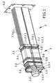
- Figure 1 shows a heat exchanger with a floating core, comprising a flow deflector (3) such as that of the present invention.
- Said heat exchanger comprises a core (2) formed by a bundle (2.1) of tubes, in this case planar tubes, a fixing baffle (2.2) located at one end of the bundle (2.1) of tubes of said core (2), and a bushing (2.3) located at the opposite end suitable for the floating attachment of the core (2).
- the bundle (2.1) of tubes is fixed to the fixing baffle (2.2), such that movement due to longitudinal expansion with respect to the shell (1) housing the bundle (2.1) of tubes is allowed at the end of the bushing (2.3) to reduce the thermal fatigue of the device during operation.
- the flow deflector (3) is formed by two portions attached to one another by means of clipping through an assembly of flanges (3.6) on each side.
- the flow deflector (3) has a tubular body (3.1) extending along a portion of the length of the bundle (2.1) of tubes, completely surrounding the tubes forming said bundle (2.1) of tubes.
- the flow deflector (3) comprises at its ends a first expansion section (3.2) and a second expansion section (3.3), having a larger perimeter than the tubular body (3.1) and in which a series of longitudinal grooves (3.2.1, 3.3.1) are machined.
- the portions giving rise to the deflector (3) are manufactured in die-cut and pressed sheet metal.
- the longitudinal grooves (3.2.1, 3.3.1) are obtained in these same die-cutting operations.
- the main function of the first expansion section (3.2) and the second expansion section (3.3) is to act as a funnel, directing the directed entry and exit of most of the first coolant fluid flow through the flow channel formed by the space comprised between the tubes of the bundle (2.1) of tubes, or inner space, preventing part of said flow from going through the space existing between the bundle (2.1) of tubes and the shell (1), or perimetral gap.
- the expression "most of the flow” is used since there may be small clearances or, as can be seen below, grooves (3.2.1, 3.3.1) which allow certain portions of the deflector to bend, giving rise to small amounts of flow compared with the main flow without these minor flows preventing the increase in heat exchanger efficiency.
- the flow deflector (3) also comprises a window (3.4) located at one of its ends, both on the tubular body (3.1) and on one of the expansion sections (3.2, 3.3).
- the flow deflector (3) also comprises a plurality of perimetral expansions (3.5) allowing both axially fixing the flow deflector (3), and housing a series of baffles (2.1.1) integral with the bundle (2.1) of tubes, which are in turn flow deflectors inside the channel formed between the tubes of the bundle (2.1) of tubes, or inner space.
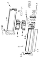
- Figure 2 shows a heat exchanger according to an exploded view with all its elements together with a flow deflector (3) such as that of the present invention.
- FIG. 3a and 3b show a section view of the shell (1) of the heat exchanger together with its inner chamber (H).
- the core (2) and the distribution of all its elements are also shown.
- the bundle (2.1) of tubes comprises a plurality of planar tubes which are attached at one of their ends to the fixing baffle (2.2), whereas their other end is attached to the bushing (2.3) allowing thermal expansion, and therefore enabling longitudinal movement of the tubes of the bundle (2.1) of tubes.
- the core (2) also has baffles (2.1.1) with holes in their entire longitudinal extension or only in part of said longitudinal extension, allowing said baffles (2.1.1) to be inserted in the tubes of the bundle (2.1) of tubes.
- These baffles (2.1.1) have regions for passage located alternately according to a transverse direction such that they modify the path of the first coolant fluid flow when such coolant fluid circulates through the channel defined between the tubes, or inner space.
- a flow deflector (3) is also shown, formed in this case by two portions attached to one another by means of clipping as seen in Figure 1 as well.
- This flow deflector (3) comprises at least as many perimetral expansions (3.5) as baffles (2.1.1) comprised in the core (2), where each of the expansions (3.5) houses the perimetral projection of each of the baffles (2.1.1). According to other embodiments, there may be more expansions (3.5) without all the expansions (3.5) having to house a baffle (2.1.1).
- expansions (3.5) coinciding with the baffles (2.1.1) of both exchangers are included such that there will be expansions (3.5) not housing a baffle (2.1.1) in any one of the exchangers.
- These expansions (3.5) not housing a baffle (2.1.1) do not reduce deflector efficiency.
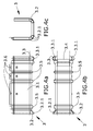
- FIG. 3a shows a plan view of a heat exchanger such as that of the preceding figures, already mounted.
- Said plan view is a section of the shell to allow observing the mounted system therein, and in which the main portions of said shell (1), such as the main body (1.1) of the shell, comprising the inner chamber (H) and therefore the bundle (2.1) of tubes, and a cover flange (1.2), are distinguished.
- Said flange (1.2) in contact with the fixing baffle (2.2), prevents the first coolant fluid from leaking out of the heat exchanger, in addition to keeping both the fixing baffle (2.2) and the corresponding end of the bundle (2.1) of tubes fixed in place.
- FIG 3b shows an elevational view of a heat exchanger such as that of the preceding figures, already mounted.
- Said elevational view is a cut through the shell to allow observing the inside of the mounted system, like in Figure 3a , and in which the main portions of said shell (1), such as the main body (1.1) of the shell, comprising the inner chamber (H) and therefore the bundle (2.1) of tubes, and the cover flange (1.2), are distinguished.
- This figure shows the flow deflector (3) formed by two portions, already mounted and attached by means of the flanges (3.6) and the corresponding housings, giving rise to a clipped attachment.
- Figures 4a-4c show different views of one of the portions of the flow deflector (3).
- a flow deflector (3) is mounted by combining two of these portions. The combination is possible since the flanges (3.6) and the housings holding these flanges (3.6) are positioned such that when two equal parts or portions are coupled to one another, the flanges (3.6) enter the corresponding housings.
- Figure 4a is an elevational view of the flow deflector (3) in which are distinguished both the tubular body (3.1) and the perimetral expansions (3.5) housing the baffles (2.1.1) which, in operating position, will coincide with one another according to the longitudinal direction defined by the bundle (2.1) of tubes.
- the flanges (3.6) that allow clipping are also distinguished.
- Said flanges (3.6) also have an assembly of projections that are coupled in the housings of the opposite portion and serve to keep said portions firmly attached.
- Figure 4b shows the plan view of the flow deflector (3), both the expansion sections (3.2, 3.3) and, like in the preceding figure, the perimetral expansions (3.5) being distinguished.
- the window (3.4) made on the tubular body (3.1) and on the second expansion section (3.3) is also shown.
- This window (3.4) is configured so that it is positioned in the region for accessing the inlet or outlet conduit (1.3, 1.4) of the first coolant fluid located in the shell (1) once the deflector (3) is mounted in the operating position on the bundle (2.1) of tubes.
- the expansion sections (3.2, 3.3) are formed according to a curved section and have longitudinal grooves (3.2.1, 3.3.1) obtained when die-cutting, for example, leaving between them elastically deformable sections adapted for bending.
- the deformation of the elastically deformable sections caused by the force exerted by the inner wall of the shell (1) gives rise to a configuration in which the expansion sections (3.2, 3.3) have grooves (3.2.1, 3.3.1) that are closed or closed to a greater extent such that the possible leak flow passage through these chinks is reduced.
- the width of the grooves (3.2.1, 3.3.1) is such that the elastically deformable sections adopt a closed configuration after the deformation caused by the shell (1), i.e., is reduced to not allow passage therethrough with the exception of positioning errors due to irregularities of the inner wall of the shell (1) or variations in the way of being deformed due to mounting.
- Figure 4c shows a side view of the flow deflector (3) where the curved section of the first expansion section (3.2) is also seen together with its longitudinal grooves (3.2.1, 3.3.1).
Abstract
Description
- The present invention relates to a device for deflecting coolant fluid flow in a heat exchanger, particularly a heat exchanger of an EGR (Exhaust Gas Recirculation) system, better cooling of the fluid to be cooled and flowing through the bundle of tubes of said heat exchanger being obtained.
- Heat exchangers comprise bundles of tubes which are housed in a shell, and a flow channel of a first fluid, the coolant fluid, is generated in the space existing between said tubes and the shell. A second fluid cooled by the first fluid flowing through the outside of the tubes, removing heat by convection, circulates inside the tubes forming the bundle.
- Two types of spaces are distinguished in this heat exchanger configuration, i.e., the space existing between the tubes of the bundle of tubes and the space between the bundle of tubes and the shell.
- When the heat exchanger has a very compact bundle of tubes, the ratio of space existing between the shell and the tubes to space existing between the tubes themselves is relevant for first coolant fluid flow which tends to flow through said first space located between the shell and the tubes as there is less resistance, cooling efficiency being reduced.
- The absence of cooling causes overheating in non-cooled areas with respect to other surrounding areas and therefore higher risk of thermal fatigue failure.
- To reduce this risk of thermal fatigue failure, there are heat exchangers comprising floating cores where the bundle of tubes comprises an element in at least one of its ends allowing the longitudinal displacement necessary to compensate for differential thermal expansion between the core and the shell, such that said expansions do not generate stress.
- To increase heat exchanger cooling efficiency, there are plates welded to the shell restricting the first coolant fluid flow through the space located between the shell and the bundle of tubes, concentrating this first fluid flow through the space located between tubes. Nevertheless, these welded plates make mounting a floating core in the heat exchanger difficult, and they cannot completely restrict the space since mechanical interferences with the core would be produced in the event of the existence of vibrations, which would end up causing structural damage.
- The present invention proposes a solution to the preceding problems by means of a flow deflection system.
- A first inventive aspect provides a flow deflector adapted for being installed in heat exchangers of the type comprising a shell with an inner chamber through which a first coolant fluid circulates and where said shell houses at least a bundle of tubes through which a second fluid to be cooled circulates, where between the bundle of tubes and the wall of the inner chamber of the shell there is a perimetral gap in at least one section of the length of the bundle of tubes. The deflector according to this first inventive aspect comprises:
- - a first expansion section arranged at one end of the tubular body such that the tubular body is extended longitudinally by means of the first expansion section where:
- o the first expansion section covers a larger perimeter than the perimeter covered by the tubular body to reduce the perimetral gap between the bundle of tubes and the wall of the inner chamber of the shell; and,
- o between the first expansion section and the tubular body there is a transition such that a first coolant fluid flow passage restriction is established for restricting it to the space between the tubes of the bundle of tubes. If the heat exchanger has a floating core, a space must be provided between the tubes of the bundle of tubes and the inner wall of the shell, or inner chamber, for mounting same.
- In the context of the invention, the space existing between the tubes of the bundle of tubes and the inner wall of the shell is defined as perimetral gap, whereas the space defined between the actual tubes of the bundle of tubes is referred to as inner space.
- If the heat exchanger has a very compact bundle of tubes, the ratio between the perimetral gap and the inner space is high. In these conditions, the first fluid, i.e., the coolant fluid, tends to circulate through the spaces offering less resistance, or in other words, where the section of the passage is larger. In case of a very compact bundle of tubes, the first fluid preferably runs through the channel defined between the bundle of tubes and the inner wall of the shell, or perimetral gap, such that the flow rate of the first fluid intended for flowing through the space located between the tubes of the bundle of tubes, i.e., the inner space, is reduced, and heat is removed by convection.
- In case of the heat exchanger for which the flow deflector is adapted, said heat exchanger has a perimetral gap between the inner wall of the shell and the tubes of the bundle of tubes in at least one section of the length of said tubes.
- Said perimetral gap allows mounting a floating core. Nevertheless, this perimetral gap generates a flow channel around the bundle of tubes for the first fluid different from the flow channel between the tubes of the bundle of tubes, or inner space, through which said first fluid must circulate.
- The flow deflector of the present invention allows minimizing the first coolant fluid flow rate through the first channel established through the perimetral gap located between the bundle of tubes and the inner wall of the shell.
- The deflector according to the first inventive aspect is adapted for restricting first fluid passage through the flow channel located in the perimetral gap, such that the flow is redirected towards the channel formed by the inner space. Therefore, the increase in flow rate through the channel formed by the inner space also causes an increase in speed, reducing the stagnant regions and therefore the occurrence of possible hot spots.
- The present flow deflector comprises a tubular body which is located surrounding a plurality of tubes of the bundle of tubes, preferably all of said bundle of tubes. This tubular body is extended in at least a longitudinal section of the tubes of the surrounded bundle of tubes.
- The tubular body defines a perimetral flow barrier the section of which can vary along the length of extension thereof such that once driven to the inner space, the fluid can no longer access the perimetral gap except for minimal leaks that may occur in areas where parts are attached to one another, for example.
- The flow deflector of the present invention further comprises a first expansion section located at one of the ends of the tubular body in the preferred example.
- This first expansion section defines a larger perimeter than the largest perimeter defined by the tubular body.
- Therefore, the perimetral gap defined between the bundle of tubes and the inner wall of the shell is smaller in the area where the first expansion section is located than along the length covered by the tubular body.
- In the preferred example, the first expansion section is located against the inner wall of the shell to prevent fluid passage through the perimetral gap. The transition between the first expansion section and the tubular body establishes a first coolant fluid flow passage restriction, such that the first coolant fluid is forced to circulate through the inner space. The first expansion section therefore acts as an inlet for the first coolant fluid which is collected by the area having a larger perimeter and forced to be introduced into the inner space.
- Advantageously, the flow deflector defined in the first inventive aspect concentrates the first coolant fluid in the space defined between the tubes of the bundle of tubes, i.e., it increases the first coolant fluid flow directed towards the bundle of tubes, such that cooling efficiency in said tubes increases.
- This means that the flow deflector allows the heat exchanger to require a smaller amount of coolant since it improves the proportion of the amount of first coolant fluid intended for contacting with the outer surface of the tubes, removing heat by convection. The incorporation of the deflector according to the first inventive aspect allows using lower first fluid flow rates, maintaining heat exchanger efficiency. In the state of the art, the part of the flow circulating through the perimetral gap reduces the flow circulating through the inner space, and to compensate for the reduction of discharged heat it is necessary to increase the total coolant fluid flow rate. For this reason, it is indicated that it is possible to reduce the first fluid flow rate in comparison with the exchanger without using the deflector according to the invention.
- As an additional advantage, the present deflector allows being used in heat exchangers with a floating core without hindering mounting due to the placement thereof on the tubes of the bundle of tubes of the tubular body and to the fact that it is not attached to the shell. This means that it does not restrict differential movement between the shell and the tubes of the bundle of tubes, so it does not interfere with the operation or the mounting of any type of core, be it a floating core or a rigid core.
- In a particular embodiment, the flow deflector has a tubular body comprising a second expansion section located at the end of the tubular body opposite to the end where the first expansion section is located.
- The presence of a second expansion section in the deflector advantageously allows an oriented exit of the first coolant fluid. This second expansion section acts a funnel allowing the exit of the first fluid flow, preventing it from flowing back, creating recirculation areas, and from accessing the perimetral gap existing between the inside of the shell and the tubular body, surrounding the bundle of tubes.
- In a particular embodiment, the flow deflector presents at least one elastically deformable expansion section to assure support against the wall of the inner chamber of the shell.
- This feature in at least one of the expansion sections allows supporting the flow deflector on the inner chamber of the shell. This advantageously reduces vibrations suffered by the bundle of tubes or at least causes a node in the vibration modes increasing the natural vibration frequency, reducing the probability of fatigue damage since the amplitude of core oscillations is reduced.
- In a particular embodiment, the flow deflector presents a curved section in the region in at least one of the expansion sections which is adapted for contacting with the wall of the inner chamber of the shell to prevent wedging.
- This curved section in at least one of the expansion sections assures robuster support on the wall of the inner chamber of the shell.
- In a particular embodiment, the flow deflector presents in the second expansion section at least one window to favor coolant fluid passage, both the entry and exit of said coolant fluid, between the inner space and the perimetral gap.
- In a particular embodiment, the flow deflector presents a window that is prolonged along a region of the tubular body.
- The entry or exit of the first coolant fluid to/from the heat exchanger is established through the shell in most embodiments. The entry or exit of the flow restricted by means of the tubular body through a window is faster than through the tubes of the bundle of tubes along the entire tubular body of the deflector given that it allows the flow to have a path with less resistance.
- In a particular embodiment, the flow deflector presents perimetral expansions in the tubular body for housing baffles of the bundle of tubes.
- Said perimetral expansions are sections along the tubular body where the perimeter, according to a section transverse to the longitudinal direction defined by the bundle of tubes, is greater than the perimeter defined by the tubular body, and less than or equal to the perimeter defined by the expansion section.
- The perimetral expansions advantageously allow housing flow deflector baffles located in the space between the tubes of the bundle of tubes. Said baffles guide the first coolant fluid flow according to a specific path inside the flow channel defined between the tubes of the bundle of tubes, assure the separation between the tubes and provide greater structural rigidity.
- On the other hand, the perimetral expansions advantageously provide axial retention of the flow deflector with respect to the tubes of the bundle of tubes, given that the baffles housed therein are fixed in the tubes of the bundle of tubes and the deflector is not attached by welding or by equivalent attachment means to any element of the exchanger.
- In a particular embodiment, the flow deflector is made of die-cut and pressed sheet metal. This means that the process for manufacturing said deflector is a simple and low-cost process due to the simplicity of the operations necessary both for manufacture and for subsequent assembly in the operating position.
- In a particular embodiment, the flow deflector presents elastically deformable expansion sections configured by means of longitudinal grooves making the deformation thereof easier by increasing flexibility. Longitudinal groove is understood as a groove extending according to the direction indicated by the longitudinal direction defined by the bundle of tubes. The expansion section can be configured with a curvature for being located against the inner wall of the shell without causing wedging. The groove is considered to be showing a longitudinal direction, even in this curved configuration, if the plane containing it is parallel to the longitudinal axis of the bundle of tubes. This will be the case of the embodiments described below.
- The longitudinal grooves allow the expansion sections to undergo greater deformation without negatively affecting the support they provide when contacting with the wall of the inner chamber of the shell. The insertion of the bundle of tubes in the shell, with the deflector placed in the bundle of tubes, entails bending the sheet sections located between grooves, and this bending is in turn possible as a result of the existence of said grooves. The sheet sections located between grooves contact with the wall, forcing the deformation thereof by bending such that they move closer to one another, the space formed by the grooves being reduced and assimilating the configuration that an expansion section without longitudinal grooves would have. Due to the deformation adopted by the sections located between grooves after insertion, this final configuration prevents the flow passage through the grooves since they are closed.
- This configuration advantageously means that the expansion sections with longitudinal grooves allow supporting the flow deflector against the wall of the inner chamber of the shell, thus reducing vibrations suffered by the bundle of tubes. This vibration damping is more efficient with longitudinal grooves given that they are more flexible and allow greater deformation.
- In a particular embodiment, the flow deflector is configured in two or more portions attached to one another by clipping.
- The advantage of configuring the flow deflector in two or more portions is that it can be more easily mounted on the heat exchanger. In one embodiment, the deflector is configured in two portions such that both portions enclose the bundle of tubes therein such that said portions are located in opposition.
- The different portions allow better adjustment in the position thereof to then be attached to one another through any attachment method allowing the parts to have no relative movement between them. The different parts are coupled to one another such that they are fixed together once the attachment is performed.
- Said attachment is preferably performed by clipping such that the portions of the flow deflector are provided both with flanges and housings for said flanges, allowing solid and at the same time removable anchoring of the attached parts forming the flow deflector.
- Another object of this invention is the heat exchanger comprising the deflector, the heat exchanger particularly comprising:
-
- a core comprising at least one bundle of tubes through which a second fluid to be cooled circulates where said shell houses the at least one bundle of tubes, and where between the bundle of tubes and the wall of the inner chamber of the shell, there is a perimetral gap in at least one section of the length of the bundle of tubes,
- a deflector according to the first inventive aspect located in the perimetral gap.
- A heat exchanger having these features advantageously allows more efficient cooling of the second fluid, given that it forces the first fluid to pass through the inside of the tubes of the bundle of tubes and prevents said first fluid from looking for paths through the space between the bundle of tubes and the shell, or perimetral gap.
- Furthermore, the cooling is more efficient and can be obtained with a smaller amount of first coolant fluid than in a heat exchanger that does not contain at least one flow deflector of this type.
- The foregoing and other features and advantages of the invention will become clearer based on the following detailed description of a preferred embodiment given only by way of illustrative and non-limiting example in reference to the attached drawings.
-
Figure 1 shows a perspective view of a heat exchanger with a flow deflector according to an embodiment of the invention. -
Figure 2 shows an exploded view of all the components of a heat exchanger such as that of the preceding figure. -
Figure 3a shows a plan view of a section according to a plane cutting through the shell but not the deflector of the heat exchanger shown inFigure 1 with all its components. -
Figure 3b shows an elevational view of a section according to a plane cutting through the shell but not the deflector of the heat exchanger shown inFigure 1 with all its components. -
Figure 4a shows an elevational view of a portion configuring the flow deflector through the attachment of two of these portions. -
Figure 4b shows a plan view of the same portion of the flow deflector. -
Figure 4c shows a side view of the same portion of the flow deflector. - According to the first inventive aspect, the present invention relates to a device for deflecting a first coolant fluid flow circulating through a heat exchanger.
-
Figure 1 shows a heat exchanger with a floating core, comprising a flow deflector (3) such as that of the present invention. - Said heat exchanger comprises a core (2) formed by a bundle (2.1) of tubes, in this case planar tubes, a fixing baffle (2.2) located at one end of the bundle (2.1) of tubes of said core (2), and a bushing (2.3) located at the opposite end suitable for the floating attachment of the core (2).
- The bundle (2.1) of tubes is fixed to the fixing baffle (2.2), such that movement due to longitudinal expansion with respect to the shell (1) housing the bundle (2.1) of tubes is allowed at the end of the bushing (2.3) to reduce the thermal fatigue of the device during operation.
- The flow deflector (3) according to this embodiment is formed by two portions attached to one another by means of clipping through an assembly of flanges (3.6) on each side.
- Once mounted around the core (2) of the heat exchanger, the flow deflector (3) has a tubular body (3.1) extending along a portion of the length of the bundle (2.1) of tubes, completely surrounding the tubes forming said bundle (2.1) of tubes.
- The flow deflector (3) comprises at its ends a first expansion section (3.2) and a second expansion section (3.3), having a larger perimeter than the tubular body (3.1) and in which a series of longitudinal grooves (3.2.1, 3.3.1) are machined. In this embodiment, the portions giving rise to the deflector (3) are manufactured in die-cut and pressed sheet metal. The longitudinal grooves (3.2.1, 3.3.1) are obtained in these same die-cutting operations.
- The main function of the first expansion section (3.2) and the second expansion section (3.3) is to act as a funnel, directing the directed entry and exit of most of the first coolant fluid flow through the flow channel formed by the space comprised between the tubes of the bundle (2.1) of tubes, or inner space, preventing part of said flow from going through the space existing between the bundle (2.1) of tubes and the shell (1), or perimetral gap. The expression "most of the flow" is used since there may be small clearances or, as can be seen below, grooves (3.2.1, 3.3.1) which allow certain portions of the deflector to bend, giving rise to small amounts of flow compared with the main flow without these minor flows preventing the increase in heat exchanger efficiency.
- To improve said exit of the first coolant fluid, the flow deflector (3) also comprises a window (3.4) located at one of its ends, both on the tubular body (3.1) and on one of the expansion sections (3.2, 3.3).
- The flow deflector (3) also comprises a plurality of perimetral expansions (3.5) allowing both axially fixing the flow deflector (3), and housing a series of baffles (2.1.1) integral with the bundle (2.1) of tubes, which are in turn flow deflectors inside the channel formed between the tubes of the bundle (2.1) of tubes, or inner space.
-
Figure 2 shows a heat exchanger according to an exploded view with all its elements together with a flow deflector (3) such as that of the present invention. - This figure and
Figures 3a and 3b show a section view of the shell (1) of the heat exchanger together with its inner chamber (H). - The core (2) and the distribution of all its elements are also shown. The bundle (2.1) of tubes comprises a plurality of planar tubes which are attached at one of their ends to the fixing baffle (2.2), whereas their other end is attached to the bushing (2.3) allowing thermal expansion, and therefore enabling longitudinal movement of the tubes of the bundle (2.1) of tubes. The core (2) also has baffles (2.1.1) with holes in their entire longitudinal extension or only in part of said longitudinal extension, allowing said baffles (2.1.1) to be inserted in the tubes of the bundle (2.1) of tubes. These baffles (2.1.1) have regions for passage located alternately according to a transverse direction such that they modify the path of the first coolant fluid flow when such coolant fluid circulates through the channel defined between the tubes, or inner space.
- A flow deflector (3) is also shown, formed in this case by two portions attached to one another by means of clipping as seen in
Figure 1 as well. - This flow deflector (3) comprises at least as many perimetral expansions (3.5) as baffles (2.1.1) comprised in the core (2), where each of the expansions (3.5) houses the perimetral projection of each of the baffles (2.1.1). According to other embodiments, there may be more expansions (3.5) without all the expansions (3.5) having to house a baffle (2.1.1). This is the case of deflectors manufactured with a single configuration which are valid for two different exchangers with baffle distributions that are also different. In this particular case, for example, expansions (3.5) coinciding with the baffles (2.1.1) of both exchangers are included such that there will be expansions (3.5) not housing a baffle (2.1.1) in any one of the exchangers. These expansions (3.5) not housing a baffle (2.1.1) do not reduce deflector efficiency.
-
Figure 3a shows a plan view of a heat exchanger such as that of the preceding figures, already mounted. Said plan view is a section of the shell to allow observing the mounted system therein, and in which the main portions of said shell (1), such as the main body (1.1) of the shell, comprising the inner chamber (H) and therefore the bundle (2.1) of tubes, and a cover flange (1.2), are distinguished. Said flange (1.2), in contact with the fixing baffle (2.2), prevents the first coolant fluid from leaking out of the heat exchanger, in addition to keeping both the fixing baffle (2.2) and the corresponding end of the bundle (2.1) of tubes fixed in place. -
Figure 3b shows an elevational view of a heat exchanger such as that of the preceding figures, already mounted. Said elevational view is a cut through the shell to allow observing the inside of the mounted system, like inFigure 3a , and in which the main portions of said shell (1), such as the main body (1.1) of the shell, comprising the inner chamber (H) and therefore the bundle (2.1) of tubes, and the cover flange (1.2), are distinguished. This figure shows the flow deflector (3) formed by two portions, already mounted and attached by means of the flanges (3.6) and the corresponding housings, giving rise to a clipped attachment. -
Figures 4a-4c show different views of one of the portions of the flow deflector (3). A flow deflector (3) is mounted by combining two of these portions. The combination is possible since the flanges (3.6) and the housings holding these flanges (3.6) are positioned such that when two equal parts or portions are coupled to one another, the flanges (3.6) enter the corresponding housings. -
Figure 4a is an elevational view of the flow deflector (3) in which are distinguished both the tubular body (3.1) and the perimetral expansions (3.5) housing the baffles (2.1.1) which, in operating position, will coincide with one another according to the longitudinal direction defined by the bundle (2.1) of tubes. The flanges (3.6) that allow clipping are also distinguished. Said flanges (3.6) also have an assembly of projections that are coupled in the housings of the opposite portion and serve to keep said portions firmly attached. -
Figure 4b shows the plan view of the flow deflector (3), both the expansion sections (3.2, 3.3) and, like in the preceding figure, the perimetral expansions (3.5) being distinguished. - The window (3.4) made on the tubular body (3.1) and on the second expansion section (3.3) is also shown. This window (3.4) is configured so that it is positioned in the region for accessing the inlet or outlet conduit (1.3, 1.4) of the first coolant fluid located in the shell (1) once the deflector (3) is mounted in the operating position on the bundle (2.1) of tubes.
- The expansion sections (3.2, 3.3) are formed according to a curved section and have longitudinal grooves (3.2.1, 3.3.1) obtained when die-cutting, for example, leaving between them elastically deformable sections adapted for bending.
Figures 3a and 3b depict these sections invading the space taken up by the inner wall of the shell (1). This depiction indicates that the insertion of the core (2) with the deflector (3) in the inner chamber (H) of the shell (1) causes these elastically deformable sections to bend. The deformation of the elastically deformable sections caused by the force exerted by the inner wall of the shell (1) gives rise to a configuration in which the expansion sections (3.2, 3.3) have grooves (3.2.1, 3.3.1) that are closed or closed to a greater extent such that the possible leak flow passage through these chinks is reduced. - Therefore, the width of the grooves (3.2.1, 3.3.1) is such that the elastically deformable sections adopt a closed configuration after the deformation caused by the shell (1), i.e., is reduced to not allow passage therethrough with the exception of positioning errors due to irregularities of the inner wall of the shell (1) or variations in the way of being deformed due to mounting.
- Likewise, there may be certain points that do not give rise to complete closure, such as the root of the grooves (3.2.1, 3.3.1), having a suitable radius preventing the occurrence of cracks due to concentrated stress.
-
Figure 4c shows a side view of the flow deflector (3) where the curved section of the first expansion section (3.2) is also seen together with its longitudinal grooves (3.2.1, 3.3.1).
Claims (11)
- A flow deflector (3) adapted for being installed in heat exchangers of the type comprising a shell (1) with an inner chamber (H) through which a first coolant fluid circulates and where said shell (1) houses at least a bundle (2.1) of tubes through which a second fluid to be cooled circulates, where between the bundle (2.1) of tubes and the wall of the inner chamber (H) of the shell (1) there is a perimetral gap in at least one section of the length of the bundle (2.1) of tubes, where said deflector (3) comprises:- a tubular body (3.1) adapted for surrounding at least one section of the length of the bundle (2.1) of tubes,- a first expansion section (3.2) arranged at one end of the tubular body (3.1) such that the tubular body (3.1) is extended longitudinally by means of the first expansion section (3.2) where:o the first expansion section (3.2) covers a larger perimeter than the perimeter covered by the tubular body (3.1) to reduce the perimetral gap between the bundle (2.1) of tubes and the wall of the inner chamber (H) of the shell (1); and,o between the first expansion section (3.2) and the tubular body (3.1) there is a transition such that a first coolant fluid flow passage restriction is established for restricting it to the space between the tubes of the bundle (2.1) of tubes.
- The flow deflector according to claim 1, where the tubular body (3.1) comprises a second expansion section (3.3) located at the end of the tubular body (3.1) opposite to the end where the first expansion section (3.2) is located.
- The flow deflector according to claim 1 or 2, where at least one of the expansion sections (3.2, 3.3) is elastically deformable to assure support against the wall of the inner chamber (H) of the shell (1).
- The flow deflector according to any of the preceding claims, where at least one of the expansion sections (3.2, 3.3) comprises a curved section in the region adapted for contacting with the wall of the inner chamber (H) of the shell (1) to prevent wedging.
- The flow deflector according to any of the preceding claims, where the second expansion section (3.3) has at least one window (3.4) to favor the coolant fluid passage through the space between the tubes of the bundle (2.1) of tubes and the gap between the bundle (2.1) of tubes and the wall of the inner chamber (H) of the shell (1).
- The flow deflector according to claim 5, where the window (3.4) is prolonged along a region of the tubular body (3.1).
- The flow deflector according to any of the preceding claims, where the tubular body (3.1) comprises perimetral expansions (3.5) for housing baffles (2.1.1) of the bundle (2.1) of tubes.
- The flow deflector according to any of the preceding claims, where the deflector (3) is made of die-cut and pressed sheet.
- The flow deflector according to any of the preceding claims, where the elastically deformable expansion sections (3.2, 3.3) are configured by means of longitudinal grooves (3.2.1, 3.3.1), according to the longitudinal direction defined by the bundle (2.1) of tubes, making deformation easier.
- The flow deflector according to any of the preceding claims, where the deflector (3) is configured in two or more portions attached to one another by clipping.
- A heat exchanger comprising:- a shell (1) with an inner chamber (H) through which a first coolant fluid circulates,- a core (2) comprising at least a bundle (2.1) of tubes through which a second fluid to be cooled circulates, where said shell (1) houses the at least one bundle of tubes (2.1), and where between the bundle (2.1) of tubes and the wall of the inner chamber (H) of the shell (1) there is a perimetral gap in at least one section of the length of the bundle (2.1) of tubes,- a deflector (3) according to any of claims 1 to 10 located in the perimetral gap.
Priority Applications (5)
| Application Number | Priority Date | Filing Date | Title |
|---|---|---|---|
| EP14382234.4A EP2957852B1 (en) | 2014-06-17 | 2014-06-17 | Flow deflectors |
| BR102015014389-3A BR102015014389A2 (en) | 2014-06-17 | 2015-06-17 | FLOW DEFLECTOR AND HEAT EXCHANGER |
| US14/741,571 US20150362264A1 (en) | 2014-06-17 | 2015-06-17 | Flow deflector |
| KR1020150085775A KR20150144723A (en) | 2014-06-17 | 2015-06-17 | Flow deflector |
| CN201510338282.0A CN105202965A (en) | 2014-06-17 | 2015-06-17 | Flow deflectors |
Applications Claiming Priority (1)
| Application Number | Priority Date | Filing Date | Title |
|---|---|---|---|
| EP14382234.4A EP2957852B1 (en) | 2014-06-17 | 2014-06-17 | Flow deflectors |
Publications (2)
| Publication Number | Publication Date |
|---|---|
| EP2957852A1 true EP2957852A1 (en) | 2015-12-23 |
| EP2957852B1 EP2957852B1 (en) | 2018-12-05 |
Family
ID=51357886
Family Applications (1)
| Application Number | Title | Priority Date | Filing Date |
|---|---|---|---|
| EP14382234.4A Not-in-force EP2957852B1 (en) | 2014-06-17 | 2014-06-17 | Flow deflectors |
Country Status (5)
| Country | Link |
|---|---|
| US (1) | US20150362264A1 (en) |
| EP (1) | EP2957852B1 (en) |
| KR (1) | KR20150144723A (en) |
| CN (1) | CN105202965A (en) |
| BR (1) | BR102015014389A2 (en) |
Cited By (2)
| Publication number | Priority date | Publication date | Assignee | Title |
|---|---|---|---|---|
| DE102017218254A1 (en) * | 2017-10-12 | 2019-04-18 | Mahle International Gmbh | Exhaust gas heat exchanger |
| DE102017130153A1 (en) * | 2017-12-15 | 2019-06-19 | Hanon Systems | Device for heat transfer |
Families Citing this family (4)
| Publication number | Priority date | Publication date | Assignee | Title |
|---|---|---|---|---|
| ES2632687B1 (en) * | 2016-03-14 | 2018-06-25 | Valeo Térmico, S. A. | HEAT EXCHANGER FOR GASES, ESPECIALLY OF EXHAUST GASES OF AN ENGINE |
| DE102016011254A1 (en) | 2016-09-20 | 2018-03-22 | Modine Manufacturing Company | Bypass blocking device for heat exchangers |
| ES2765014A1 (en) * | 2018-12-05 | 2020-06-05 | Valeo Termico Sa | HEAT EXCHANGER FOR GASES, ESPECIALLY FOR EXHAUST GASES FROM AN ENGINE (Machine-translation by Google Translate, not legally binding) |
| CN109855442B (en) * | 2018-12-29 | 2024-02-27 | 上海工程技术大学 | Medium participation radiation heating gasification device |
Citations (4)
| Publication number | Priority date | Publication date | Assignee | Title |
|---|---|---|---|---|
| BE477254A (en) * | ||||
| DE102006051000A1 (en) * | 2005-10-26 | 2007-07-12 | Behr Gmbh & Co. Kg | Exhaust gas heat exchanger for internal combustion engine of motor vehicle, has sealing unit provided in sectional contact with one of mediums, and turbulence generator provided within housing, where medium is passed within generator |
| EP1876391A1 (en) * | 2006-07-06 | 2008-01-09 | Balcke-Dürr GmbH | Heat Exchanger and Method for its Fabrication |
| JP2008297993A (en) * | 2007-05-31 | 2008-12-11 | Komatsu Ltd | Egr cooler |
Family Cites Families (9)
| Publication number | Priority date | Publication date | Assignee | Title |
|---|---|---|---|---|
| US1669291A (en) * | 1926-03-08 | 1928-05-08 | Foster Wheeler Corp | Heat exchanger |
| US1794336A (en) * | 1929-07-06 | 1931-02-24 | Alco Products Inc | Heat-exchanger apparatus |
| US2988335A (en) * | 1958-03-06 | 1961-06-13 | Gen Motors Corp | Heat exchangers |
| US3151674A (en) * | 1959-05-15 | 1964-10-06 | Licencia Talalmanyokat | Waer distributor chamber for heat exchangers and partitions therefor |
| FR1594463A (en) * | 1968-12-13 | 1970-06-01 | ||
| US4834173A (en) * | 1987-11-20 | 1989-05-30 | American Standard Inc. | Pressure actuated baffle seal |
| DE19849574B8 (en) * | 1998-10-27 | 2010-02-11 | Valeo Klimatechnik Gmbh & Co. Kg | Pipe connection between a collector of a motor vehicle heat exchanger and an outer pipe for the internal heat exchange fluid |
| DE10219964B4 (en) * | 2001-05-08 | 2009-10-29 | Umfotec Gmbh | RF attenuator |
| DE102009020306A1 (en) * | 2008-05-12 | 2010-02-11 | Modine Manufacturing Co., Racine | Heat exchanger and method of assembly |
-
2014
- 2014-06-17 EP EP14382234.4A patent/EP2957852B1/en not_active Not-in-force
-
2015
- 2015-06-17 BR BR102015014389-3A patent/BR102015014389A2/en not_active Application Discontinuation
- 2015-06-17 US US14/741,571 patent/US20150362264A1/en not_active Abandoned
- 2015-06-17 KR KR1020150085775A patent/KR20150144723A/en not_active Application Discontinuation
- 2015-06-17 CN CN201510338282.0A patent/CN105202965A/en active Pending
Patent Citations (4)
| Publication number | Priority date | Publication date | Assignee | Title |
|---|---|---|---|---|
| BE477254A (en) * | ||||
| DE102006051000A1 (en) * | 2005-10-26 | 2007-07-12 | Behr Gmbh & Co. Kg | Exhaust gas heat exchanger for internal combustion engine of motor vehicle, has sealing unit provided in sectional contact with one of mediums, and turbulence generator provided within housing, where medium is passed within generator |
| EP1876391A1 (en) * | 2006-07-06 | 2008-01-09 | Balcke-Dürr GmbH | Heat Exchanger and Method for its Fabrication |
| JP2008297993A (en) * | 2007-05-31 | 2008-12-11 | Komatsu Ltd | Egr cooler |
Cited By (5)
| Publication number | Priority date | Publication date | Assignee | Title |
|---|---|---|---|---|
| DE102017218254A1 (en) * | 2017-10-12 | 2019-04-18 | Mahle International Gmbh | Exhaust gas heat exchanger |
| US11655745B2 (en) | 2017-10-12 | 2023-05-23 | Mahle International Gmbh | Exhaust gas heat exchanger |
| DE102017130153A1 (en) * | 2017-12-15 | 2019-06-19 | Hanon Systems | Device for heat transfer |
| US10900446B2 (en) | 2017-12-15 | 2021-01-26 | Hanon Systems | Device for heat transfer |
| DE102017130153B4 (en) | 2017-12-15 | 2022-12-29 | Hanon Systems | Heat transfer device and method of making the device |
Also Published As
| Publication number | Publication date |
|---|---|
| CN105202965A (en) | 2015-12-30 |
| BR102015014389A2 (en) | 2017-07-11 |
| KR20150144723A (en) | 2015-12-28 |
| US20150362264A1 (en) | 2015-12-17 |
| EP2957852B1 (en) | 2018-12-05 |
Similar Documents
| Publication | Publication Date | Title |
|---|---|---|
| EP2957852B1 (en) | Flow deflectors | |
| KR101925201B1 (en) | Heat exchange device | |
| KR101974764B1 (en) | Heat recovery device and exhaust line fitted with such device | |
| EP2912296B1 (en) | Flow deflector | |
| CN106066128B (en) | Heat exchange device | |
| EP3029407A1 (en) | Grooved baffle for a heat exchanger | |
| US9400143B2 (en) | Device for reducing the vibrations of a tube bundle of a heat exchanger inside its shell | |
| JP2020516846A (en) | Heat exchanger for motor vehicles | |
| CN107850404B (en) | Shell-and-tube equipment with vibration-proof baffle and related assembly method | |
| CN109458279B (en) | Compact heat exchanger | |
| CN109149845B (en) | Totally enclosed rotating electrical machine and noise reduction structure | |
| CN112313468B (en) | Heat exchanger | |
| JP6135057B2 (en) | Intercooler for vehicle | |
| EP2955469A1 (en) | Baffle suitable for evaporators | |
| KR102406998B1 (en) | Intercooler | |
| JP5664433B2 (en) | Heat exchanger | |
| CN111148961B (en) | Exhaust gas heat exchanger | |
| CN109154478B (en) | Heat exchanger for gases, in particular for engine exhaust gases | |
| CN219141578U (en) | Heat exchanger | |
| JP5337840B2 (en) | Waste heat recovery device | |
| US11193715B2 (en) | Method and system for cooling a fluid with a microchannel evaporator | |
| JP2009074768A (en) | Heat exchanger | |
| EP3376147A1 (en) | Heat exchanger assembly | |
| TW202400936A (en) | Flow conditioning device for steam generator | |
| KR20200124582A (en) | Cooler for exhaust gas recirculation |
Legal Events
| Date | Code | Title | Description |
|---|---|---|---|
| PUAI | Public reference made under article 153(3) epc to a published international application that has entered the european phase |
Free format text: ORIGINAL CODE: 0009012 |
|
| AK | Designated contracting states |
Kind code of ref document: A1 Designated state(s): AL AT BE BG CH CY CZ DE DK EE ES FI FR GB GR HR HU IE IS IT LI LT LU LV MC MK MT NL NO PL PT RO RS SE SI SK SM TR |
|
| AX | Request for extension of the european patent |
Extension state: BA ME |
|
| 17P | Request for examination filed |
Effective date: 20160505 |
|
| RBV | Designated contracting states (corrected) |
Designated state(s): AL AT BE BG CH CY CZ DE DK EE ES FI FR GB GR HR HU IE IS IT LI LT LU LV MC MK MT NL NO PL PT RO RS SE SI SK SM TR |
|
| STAA | Information on the status of an ep patent application or granted ep patent |
Free format text: STATUS: EXAMINATION IS IN PROGRESS |
|
| 17Q | First examination report despatched |
Effective date: 20180205 |
|
| GRAP | Despatch of communication of intention to grant a patent |
Free format text: ORIGINAL CODE: EPIDOSNIGR1 |
|
| STAA | Information on the status of an ep patent application or granted ep patent |
Free format text: STATUS: GRANT OF PATENT IS INTENDED |
|
| RIC1 | Information provided on ipc code assigned before grant |
Ipc: F28D 21/00 20060101ALI20180219BHEP Ipc: F28D 7/16 20060101ALN20180219BHEP Ipc: F28F 9/00 20060101AFI20180219BHEP Ipc: F02M 26/32 20160101ALI20180219BHEP Ipc: F28F 13/08 20060101ALI20180219BHEP Ipc: F28F 9/22 20060101ALI20180219BHEP |
|
| INTG | Intention to grant announced |
Effective date: 20180309 |
|
| GRAJ | Information related to disapproval of communication of intention to grant by the applicant or resumption of examination proceedings by the epo deleted |
Free format text: ORIGINAL CODE: EPIDOSDIGR1 |
|
| STAA | Information on the status of an ep patent application or granted ep patent |
Free format text: STATUS: EXAMINATION IS IN PROGRESS |
|
| GRAP | Despatch of communication of intention to grant a patent |
Free format text: ORIGINAL CODE: EPIDOSNIGR1 |
|
| STAA | Information on the status of an ep patent application or granted ep patent |
Free format text: STATUS: GRANT OF PATENT IS INTENDED |
|
| INTC | Intention to grant announced (deleted) | ||
| INTG | Intention to grant announced |
Effective date: 20180709 |
|
| RIC1 | Information provided on ipc code assigned before grant |
Ipc: F28F 13/08 20060101ALI20180629BHEP Ipc: F02M 26/32 20160101ALI20180629BHEP Ipc: F28F 9/00 20060101AFI20180629BHEP Ipc: F28D 21/00 20060101ALI20180629BHEP Ipc: F28D 7/16 20060101ALN20180629BHEP Ipc: F28F 9/22 20060101ALI20180629BHEP |
|
| GRAS | Grant fee paid |
Free format text: ORIGINAL CODE: EPIDOSNIGR3 |
|
| GRAA | (expected) grant |
Free format text: ORIGINAL CODE: 0009210 |
|
| STAA | Information on the status of an ep patent application or granted ep patent |
Free format text: STATUS: THE PATENT HAS BEEN GRANTED |
|
| AK | Designated contracting states |
Kind code of ref document: B1 Designated state(s): AL AT BE BG CH CY CZ DE DK EE ES FI FR GB GR HR HU IE IS IT LI LT LU LV MC MK MT NL NO PL PT RO RS SE SI SK SM TR |
|
| REG | Reference to a national code |
Ref country code: GB Ref legal event code: FG4D |
|
| REG | Reference to a national code |
Ref country code: CH Ref legal event code: EP |
|
| REG | Reference to a national code |
Ref country code: AT Ref legal event code: REF Ref document number: 1073584 Country of ref document: AT Kind code of ref document: T Effective date: 20181215 |
|
| REG | Reference to a national code |
Ref country code: IE Ref legal event code: FG4D |
|
| REG | Reference to a national code |
Ref country code: DE Ref legal event code: R096 Ref document number: 602014037348 Country of ref document: DE |
|
| REG | Reference to a national code |
Ref country code: NL Ref legal event code: MP Effective date: 20181205 |
|
| REG | Reference to a national code |
Ref country code: AT Ref legal event code: MK05 Ref document number: 1073584 Country of ref document: AT Kind code of ref document: T Effective date: 20181205 |
|
| REG | Reference to a national code |
Ref country code: LT Ref legal event code: MG4D |
|
| PG25 | Lapsed in a contracting state [announced via postgrant information from national office to epo] |
Ref country code: FI Free format text: LAPSE BECAUSE OF FAILURE TO SUBMIT A TRANSLATION OF THE DESCRIPTION OR TO PAY THE FEE WITHIN THE PRESCRIBED TIME-LIMIT Effective date: 20181205 Ref country code: NO Free format text: LAPSE BECAUSE OF FAILURE TO SUBMIT A TRANSLATION OF THE DESCRIPTION OR TO PAY THE FEE WITHIN THE PRESCRIBED TIME-LIMIT Effective date: 20190305 Ref country code: HR Free format text: LAPSE BECAUSE OF FAILURE TO SUBMIT A TRANSLATION OF THE DESCRIPTION OR TO PAY THE FEE WITHIN THE PRESCRIBED TIME-LIMIT Effective date: 20181205 Ref country code: LT Free format text: LAPSE BECAUSE OF FAILURE TO SUBMIT A TRANSLATION OF THE DESCRIPTION OR TO PAY THE FEE WITHIN THE PRESCRIBED TIME-LIMIT Effective date: 20181205 Ref country code: BG Free format text: LAPSE BECAUSE OF FAILURE TO SUBMIT A TRANSLATION OF THE DESCRIPTION OR TO PAY THE FEE WITHIN THE PRESCRIBED TIME-LIMIT Effective date: 20190305 Ref country code: ES Free format text: LAPSE BECAUSE OF FAILURE TO SUBMIT A TRANSLATION OF THE DESCRIPTION OR TO PAY THE FEE WITHIN THE PRESCRIBED TIME-LIMIT Effective date: 20181205 Ref country code: LV Free format text: LAPSE BECAUSE OF FAILURE TO SUBMIT A TRANSLATION OF THE DESCRIPTION OR TO PAY THE FEE WITHIN THE PRESCRIBED TIME-LIMIT Effective date: 20181205 Ref country code: AT Free format text: LAPSE BECAUSE OF FAILURE TO SUBMIT A TRANSLATION OF THE DESCRIPTION OR TO PAY THE FEE WITHIN THE PRESCRIBED TIME-LIMIT Effective date: 20181205 |
|
| PG25 | Lapsed in a contracting state [announced via postgrant information from national office to epo] |
Ref country code: AL Free format text: LAPSE BECAUSE OF FAILURE TO SUBMIT A TRANSLATION OF THE DESCRIPTION OR TO PAY THE FEE WITHIN THE PRESCRIBED TIME-LIMIT Effective date: 20181205 Ref country code: RS Free format text: LAPSE BECAUSE OF FAILURE TO SUBMIT A TRANSLATION OF THE DESCRIPTION OR TO PAY THE FEE WITHIN THE PRESCRIBED TIME-LIMIT Effective date: 20181205 Ref country code: GR Free format text: LAPSE BECAUSE OF FAILURE TO SUBMIT A TRANSLATION OF THE DESCRIPTION OR TO PAY THE FEE WITHIN THE PRESCRIBED TIME-LIMIT Effective date: 20190306 Ref country code: SE Free format text: LAPSE BECAUSE OF FAILURE TO SUBMIT A TRANSLATION OF THE DESCRIPTION OR TO PAY THE FEE WITHIN THE PRESCRIBED TIME-LIMIT Effective date: 20181205 |
|
| PG25 | Lapsed in a contracting state [announced via postgrant information from national office to epo] |
Ref country code: NL Free format text: LAPSE BECAUSE OF FAILURE TO SUBMIT A TRANSLATION OF THE DESCRIPTION OR TO PAY THE FEE WITHIN THE PRESCRIBED TIME-LIMIT Effective date: 20181205 |
|
| PG25 | Lapsed in a contracting state [announced via postgrant information from national office to epo] |
Ref country code: CZ Free format text: LAPSE BECAUSE OF FAILURE TO SUBMIT A TRANSLATION OF THE DESCRIPTION OR TO PAY THE FEE WITHIN THE PRESCRIBED TIME-LIMIT Effective date: 20181205 Ref country code: IT Free format text: LAPSE BECAUSE OF FAILURE TO SUBMIT A TRANSLATION OF THE DESCRIPTION OR TO PAY THE FEE WITHIN THE PRESCRIBED TIME-LIMIT Effective date: 20181205 Ref country code: PT Free format text: LAPSE BECAUSE OF FAILURE TO SUBMIT A TRANSLATION OF THE DESCRIPTION OR TO PAY THE FEE WITHIN THE PRESCRIBED TIME-LIMIT Effective date: 20190405 Ref country code: PL Free format text: LAPSE BECAUSE OF FAILURE TO SUBMIT A TRANSLATION OF THE DESCRIPTION OR TO PAY THE FEE WITHIN THE PRESCRIBED TIME-LIMIT Effective date: 20181205 |
|
| PG25 | Lapsed in a contracting state [announced via postgrant information from national office to epo] |
Ref country code: SK Free format text: LAPSE BECAUSE OF FAILURE TO SUBMIT A TRANSLATION OF THE DESCRIPTION OR TO PAY THE FEE WITHIN THE PRESCRIBED TIME-LIMIT Effective date: 20181205 Ref country code: RO Free format text: LAPSE BECAUSE OF FAILURE TO SUBMIT A TRANSLATION OF THE DESCRIPTION OR TO PAY THE FEE WITHIN THE PRESCRIBED TIME-LIMIT Effective date: 20181205 Ref country code: IS Free format text: LAPSE BECAUSE OF FAILURE TO SUBMIT A TRANSLATION OF THE DESCRIPTION OR TO PAY THE FEE WITHIN THE PRESCRIBED TIME-LIMIT Effective date: 20190405 Ref country code: EE Free format text: LAPSE BECAUSE OF FAILURE TO SUBMIT A TRANSLATION OF THE DESCRIPTION OR TO PAY THE FEE WITHIN THE PRESCRIBED TIME-LIMIT Effective date: 20181205 Ref country code: SM Free format text: LAPSE BECAUSE OF FAILURE TO SUBMIT A TRANSLATION OF THE DESCRIPTION OR TO PAY THE FEE WITHIN THE PRESCRIBED TIME-LIMIT Effective date: 20181205 |
|
| REG | Reference to a national code |
Ref country code: DE Ref legal event code: R097 Ref document number: 602014037348 Country of ref document: DE |
|
| PLBE | No opposition filed within time limit |
Free format text: ORIGINAL CODE: 0009261 |
|
| STAA | Information on the status of an ep patent application or granted ep patent |
Free format text: STATUS: NO OPPOSITION FILED WITHIN TIME LIMIT |
|
| PG25 | Lapsed in a contracting state [announced via postgrant information from national office to epo] |
Ref country code: DK Free format text: LAPSE BECAUSE OF FAILURE TO SUBMIT A TRANSLATION OF THE DESCRIPTION OR TO PAY THE FEE WITHIN THE PRESCRIBED TIME-LIMIT Effective date: 20181205 Ref country code: SI Free format text: LAPSE BECAUSE OF FAILURE TO SUBMIT A TRANSLATION OF THE DESCRIPTION OR TO PAY THE FEE WITHIN THE PRESCRIBED TIME-LIMIT Effective date: 20181205 |
|
| 26N | No opposition filed |
Effective date: 20190906 |
|
| PG25 | Lapsed in a contracting state [announced via postgrant information from national office to epo] |
Ref country code: MC Free format text: LAPSE BECAUSE OF FAILURE TO SUBMIT A TRANSLATION OF THE DESCRIPTION OR TO PAY THE FEE WITHIN THE PRESCRIBED TIME-LIMIT Effective date: 20181205 |
|
| REG | Reference to a national code |
Ref country code: CH Ref legal event code: PL |
|
| GBPC | Gb: european patent ceased through non-payment of renewal fee |
Effective date: 20190617 |
|
| REG | Reference to a national code |
Ref country code: BE Ref legal event code: MM Effective date: 20190630 |
|
| PG25 | Lapsed in a contracting state [announced via postgrant information from national office to epo] |
Ref country code: TR Free format text: LAPSE BECAUSE OF FAILURE TO SUBMIT A TRANSLATION OF THE DESCRIPTION OR TO PAY THE FEE WITHIN THE PRESCRIBED TIME-LIMIT Effective date: 20181205 |
|
| PG25 | Lapsed in a contracting state [announced via postgrant information from national office to epo] |
Ref country code: GB Free format text: LAPSE BECAUSE OF NON-PAYMENT OF DUE FEES Effective date: 20190617 Ref country code: IE Free format text: LAPSE BECAUSE OF NON-PAYMENT OF DUE FEES Effective date: 20190617 |
|
| PG25 | Lapsed in a contracting state [announced via postgrant information from national office to epo] |
Ref country code: BE Free format text: LAPSE BECAUSE OF NON-PAYMENT OF DUE FEES Effective date: 20190630 Ref country code: CH Free format text: LAPSE BECAUSE OF NON-PAYMENT OF DUE FEES Effective date: 20190630 Ref country code: LU Free format text: LAPSE BECAUSE OF NON-PAYMENT OF DUE FEES Effective date: 20190617 Ref country code: LI Free format text: LAPSE BECAUSE OF NON-PAYMENT OF DUE FEES Effective date: 20190630 |
|
| PG25 | Lapsed in a contracting state [announced via postgrant information from national office to epo] |
Ref country code: FR Free format text: LAPSE BECAUSE OF NON-PAYMENT OF DUE FEES Effective date: 20190630 |
|
| PG25 | Lapsed in a contracting state [announced via postgrant information from national office to epo] |
Ref country code: CY Free format text: LAPSE BECAUSE OF FAILURE TO SUBMIT A TRANSLATION OF THE DESCRIPTION OR TO PAY THE FEE WITHIN THE PRESCRIBED TIME-LIMIT Effective date: 20181205 |
|
| PG25 | Lapsed in a contracting state [announced via postgrant information from national office to epo] |
Ref country code: MT Free format text: LAPSE BECAUSE OF FAILURE TO SUBMIT A TRANSLATION OF THE DESCRIPTION OR TO PAY THE FEE WITHIN THE PRESCRIBED TIME-LIMIT Effective date: 20181205 Ref country code: HU Free format text: LAPSE BECAUSE OF FAILURE TO SUBMIT A TRANSLATION OF THE DESCRIPTION OR TO PAY THE FEE WITHIN THE PRESCRIBED TIME-LIMIT; INVALID AB INITIO Effective date: 20140617 |
|
| PGFP | Annual fee paid to national office [announced via postgrant information from national office to epo] |
Ref country code: DE Payment date: 20210512 Year of fee payment: 8 |
|
| PG25 | Lapsed in a contracting state [announced via postgrant information from national office to epo] |
Ref country code: MK Free format text: LAPSE BECAUSE OF FAILURE TO SUBMIT A TRANSLATION OF THE DESCRIPTION OR TO PAY THE FEE WITHIN THE PRESCRIBED TIME-LIMIT Effective date: 20181205 |
|
| REG | Reference to a national code |
Ref country code: DE Ref legal event code: R119 Ref document number: 602014037348 Country of ref document: DE |
|
| PG25 | Lapsed in a contracting state [announced via postgrant information from national office to epo] |
Ref country code: DE Free format text: LAPSE BECAUSE OF NON-PAYMENT OF DUE FEES Effective date: 20230103 |