US4834173A - Pressure actuated baffle seal - Google Patents
Pressure actuated baffle seal Download PDFInfo
- Publication number
- US4834173A US4834173A US07/123,617 US12361787A US4834173A US 4834173 A US4834173 A US 4834173A US 12361787 A US12361787 A US 12361787A US 4834173 A US4834173 A US 4834173A
- Authority
- US
- United States
- Prior art keywords
- baffle
- tubes
- holes
- lips
- radial
- Prior art date
- Legal status (The legal status is an assumption and is not a legal conclusion. Google has not performed a legal analysis and makes no representation as to the accuracy of the status listed.)
- Expired - Fee Related
Links
Images


Classifications
-
- F—MECHANICAL ENGINEERING; LIGHTING; HEATING; WEAPONS; BLASTING
- F28—HEAT EXCHANGE IN GENERAL
- F28F—DETAILS OF HEAT-EXCHANGE AND HEAT-TRANSFER APPARATUS, OF GENERAL APPLICATION
- F28F9/00—Casings; Header boxes; Auxiliary supports for elements; Auxiliary members within casings
- F28F9/22—Arrangements for directing heat-exchange media into successive compartments, e.g. arrangements of guide plates
- F28F2009/222—Particular guide plates, baffles or deflectors, e.g. having particular orientation relative to an elongated casing or conduit
- F28F2009/226—Transversal partitions
-
- Y—GENERAL TAGGING OF NEW TECHNOLOGICAL DEVELOPMENTS; GENERAL TAGGING OF CROSS-SECTIONAL TECHNOLOGIES SPANNING OVER SEVERAL SECTIONS OF THE IPC; TECHNICAL SUBJECTS COVERED BY FORMER USPC CROSS-REFERENCE ART COLLECTIONS [XRACs] AND DIGESTS
- Y10—TECHNICAL SUBJECTS COVERED BY FORMER USPC
- Y10S—TECHNICAL SUBJECTS COVERED BY FORMER USPC CROSS-REFERENCE ART COLLECTIONS [XRACs] AND DIGESTS
- Y10S165/00—Heat exchange
- Y10S165/355—Heat exchange having separate flow passage for two distinct fluids
- Y10S165/40—Shell enclosed conduit assembly
- Y10S165/401—Shell enclosed conduit assembly including tube support or shell-side flow director
- Y10S165/416—Extending transverse of shell, e.g. fin, baffle
- Y10S165/42—Segmented plate
Definitions
- the subject invention generally pertains to baffles of shell-and-tube heat exchangers, and more specifically to seals associated with such baffles.
- Shell-and-tube heat exchangers often employ baffles for directing fluid through the shell in a tortuous path across the tubes.
- the baffles include holes through which the tubes extend, thereby enabling the baffles to traverse the tubes. It is important to seal any radial clearance that may exist between the holes and the tubes to prevent fluid from bypassing the baffle.
- Yet another object is to provide a seal that exerts a significantly lower radial sealing force during assembly than during operation which reduces the axial forces and minimizes damage to delicate tube fins when the tube is inserted through the baffle holes.
- a further object is to provide a baffle made of a unitary piece of plastic and having integral tube seals.
- a shell-and-tube heat exchanger includes a perforated plastic baffle for directing fluid in a tortuous path through the shell and across a bundle of heat exchanger tubes.
- the baffle traverses the tubes which extend through the holes in the baffle.
- the hole diameter is greater than the tube diameter to provide a radial clearance therebetween which accommodates radial tube misalignment within the hole and facilitates assembly.
- a thin flexible lip disposed around each hole tightly seals around each tube and extends upstream to prevent fluid from bypassing the baffle through the clearance.
- Each lip being exposed to both downstream fluid pressure (via the radial clearance) and upstream pressure, provides a pressure actuated seal that exerts a sealing force against the tubes that increase with the upstream-downstream pressure differential.
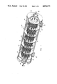
- FIG. 2 shows a longitudinal cross-section of the FIG. 1.
- FIG. 5 illustrates how the baffle seal accommodates misalignment and how the baffle can support the tube's weight.
- FIG. 6a-d illustrates the baffle accommodating various tube designs.
- the relatively large outer diameter 38 and the flexibility of lips 48 make seals 46 suitable for a variety of tube sizes and shapes as shown in FIGS. 6a-d.
- the inner diameter 50 of the unstretched lip 48 is smaller than the outer diameter 42 of a smooth land portion 54 of tube 14.
- the inner diameter 38 of holes 34 is larger than outer diameters 42 and 56 of both the land portion 54 and finned portion 58 respectively.
- diameter 42 is smaller than diameter 56; in FIG. 6b, diameter 42 is approximately equal to diameter 56; in FIG. 6c, diameter 42 is greater than diameter 56; and in FIG. 6d, tube 14 does not include a land portion 54.
- FIG. 6a illustrates the preferred embodiment, any of the tube designs of FIG. 6a-d would be acceptable, keeping in mind that the design shown in Figure d may result in some leakage across the seal.
- Baffle 16, of FIG. 7a is shown dividing fluid (water 28) between an upstream side 60 and a lower pressure downstream side 62.
- Inner diameter 38 being larger than tube diameter 42, exposes a backside 64 of the seal's lip to the lower downstream pressure, while a front side 66 of the seal's lip is exposed to the higher upstream pressure.
- the pressure differential across the baffle urges the seal's lip 48 downstream and radially against tube 14 to provide a pressure actuated seal.
- FIGS. 7b-h operate under the same basic principle.
- Baffle 16e of FIG. 7e, is a two-piece assembly having a thin flexible seal member 74e with a rigid back plate 76e.
Abstract
Description
Claims (2)
Priority Applications (4)
| Application Number | Priority Date | Filing Date | Title |
|---|---|---|---|
| US07/123,617 US4834173A (en) | 1987-11-20 | 1987-11-20 | Pressure actuated baffle seal |
| DE3811961A DE3811961A1 (en) | 1987-11-20 | 1988-04-11 | HEAT EXCHANGER |
| FR8805022A FR2623606A1 (en) | 1987-11-20 | 1988-04-15 | HEAT EXCHANGER HAVING CHICANES HAVING SEAL JOINTS |
| JP63143824A JPH01137190A (en) | 1987-11-20 | 1988-06-13 | Pressure drive baffle seal |
Applications Claiming Priority (1)
| Application Number | Priority Date | Filing Date | Title |
|---|---|---|---|
| US07/123,617 US4834173A (en) | 1987-11-20 | 1987-11-20 | Pressure actuated baffle seal |
Publications (1)
| Publication Number | Publication Date |
|---|---|
| US4834173A true US4834173A (en) | 1989-05-30 |
Family
ID=22409750
Family Applications (1)
| Application Number | Title | Priority Date | Filing Date |
|---|---|---|---|
| US07/123,617 Expired - Fee Related US4834173A (en) | 1987-11-20 | 1987-11-20 | Pressure actuated baffle seal |
Country Status (4)
| Country | Link |
|---|---|
| US (1) | US4834173A (en) |
| JP (1) | JPH01137190A (en) |
| DE (1) | DE3811961A1 (en) |
| FR (1) | FR2623606A1 (en) |
Cited By (34)
| Publication number | Priority date | Publication date | Assignee | Title |
|---|---|---|---|---|
| US5101892A (en) * | 1988-11-17 | 1992-04-07 | Kawasaki Jukogyo Kabushiki Kaisha | Heat exchanger |
| US5181561A (en) * | 1991-11-07 | 1993-01-26 | Lansing Overhaul And Repair, Inc. | Stiffener for use with a heat exchanger |
| US5285035A (en) * | 1992-11-10 | 1994-02-08 | Emerson Electric Co. | Dust proof electrical switch |
| US5641005A (en) * | 1994-12-02 | 1997-06-24 | Gas Research Institute | System and method for charging a container with pressurized gas |
| GB2313438A (en) * | 1996-05-22 | 1997-11-26 | Usui Kokusai Sangyo Kk | EGR gas cooler |
| US6092589A (en) * | 1997-12-16 | 2000-07-25 | York International Corporation | Counterflow evaporator for refrigerants |
| US20030173062A1 (en) * | 2002-03-15 | 2003-09-18 | H2Gen Innovations, Inc | Method and apparatus for minimizing adverse effects of thermal expansion in a heat exchange reactor |
| US20030178787A1 (en) * | 2002-03-19 | 2003-09-25 | Michael Christie | Self-sealing pass-through plate |
| US6772829B2 (en) * | 2001-07-05 | 2004-08-10 | Alan Lebrun | Heat exchange system and method of use |
| US20050019233A1 (en) * | 2003-07-25 | 2005-01-27 | Brewer John R. | Systems and apparatuses for stabilizing reactor furnace tubes |
| DE10333463A1 (en) * | 2003-07-22 | 2005-02-17 | Alstom Power Energy Recovery Gmbh | Tube heat exchanger |
| US20050100292A1 (en) * | 2003-11-10 | 2005-05-12 | Jds Uniphase Corporation | Transceiver guide rail with heat sink guide |
| KR100771075B1 (en) | 2007-05-30 | 2007-10-29 | 이만순 | Heat exchanger for chemical waste material |
| DE102006023639A1 (en) * | 2006-05-18 | 2007-11-22 | Technaflon Ag | Heat exchanger for recovery of heat from residual heat arising from oil-fired heating system |
| US20080006398A1 (en) * | 2006-06-22 | 2008-01-10 | Modine Manufacturing Company | Heat exchanger |
| US20080277009A1 (en) * | 2007-05-10 | 2008-11-13 | Fluid-Quip, Inc. | Multiple helical vortex baffle |
| US20090008070A1 (en) * | 2006-03-31 | 2009-01-08 | Mitsubishi Heavy Industries, Ltd. | Heat Transfer Tube Support Structure |
| US20090277606A1 (en) * | 2008-05-12 | 2009-11-12 | Reiss Iii Thomas J | Heat exchanger support and method of assembling a heat exchanger |
| US20100116478A1 (en) * | 2008-11-12 | 2010-05-13 | Exxonmobil Research And Engineering Company | Displaceable baffle for a heat exchanger and method for reducing vibration for the same |
| US20100276131A1 (en) * | 2007-09-11 | 2010-11-04 | Barwig Juergen | Heat exchanger, particularly for a motor vehicle |
| US20110067837A1 (en) * | 2006-06-22 | 2011-03-24 | Harald Schatz | Heat exchanger |
| US20110186276A1 (en) * | 2010-01-29 | 2011-08-04 | Casterton Joel T | Heat exchanger assembly and method |
| BE1018891A3 (en) * | 2009-09-23 | 2011-10-04 | Atlas Copco Airpower Nv | TUBE HEAT EXCHANGER. |
| US20110253341A1 (en) * | 2010-04-14 | 2011-10-20 | Saudi Arabian Oil Company | Auxiliary supports for heat exchanger tubes |
| CN103837024A (en) * | 2012-11-23 | 2014-06-04 | 宜兴市汇富机械设备有限公司 | Low fin type heat exchanger |
| CN103994689A (en) * | 2014-05-30 | 2014-08-20 | 威海石岛重工有限公司 | Guiding device of jacketed vessel |
| US20140262171A1 (en) * | 2013-03-14 | 2014-09-18 | Koch Heat Transfer Company, Lp | Tube bundle for shell-and-tube heat exchanger and method of constructing same |
| US20150362264A1 (en) * | 2014-06-17 | 2015-12-17 | Borgwarner Emissions Systems Spain, S.L.U. | Flow deflector |
| CN105806102A (en) * | 2016-05-31 | 2016-07-27 | 中冶焦耐工程技术有限公司 | Heat exchanger with flow guide device adopting self-supporting structure |
| US20170211895A1 (en) * | 2016-01-21 | 2017-07-27 | Fulton Group N.A., Inc. | Baffle assembly for a heat exchanger, heat exchanger including the baffle assembly, fluid heating system including the same, and methods of manufacture thereof |
| EP3364141A1 (en) * | 2017-02-15 | 2018-08-22 | Casale Sa | Shell-and-tube apparatus with baffles |
| US10247456B2 (en) * | 2010-10-27 | 2019-04-02 | Honeywell International Inc. | Integrated receiver and suction line heat exchanger for refrigerant systems |
| CN113405382A (en) * | 2021-06-25 | 2021-09-17 | 广州市壹套节能设备有限责任公司 | Shell and tube heat exchanger |
| CN113776375A (en) * | 2021-08-27 | 2021-12-10 | 核动力运行研究所 | Flexible support system for heat transfer tube bundle of heat exchanger |
Families Citing this family (2)
| Publication number | Priority date | Publication date | Assignee | Title |
|---|---|---|---|---|
| CN103557727A (en) * | 2013-11-25 | 2014-02-05 | 张家港市江南锅炉压力容器有限公司 | Heat exchanger |
| KR20210012573A (en) * | 2019-07-25 | 2021-02-03 | 엘지전자 주식회사 | Heat exchanger |
Citations (20)
| Publication number | Priority date | Publication date | Assignee | Title |
|---|---|---|---|---|
| DD80721A (en) * | ||||
| DE134984C (en) * | ||||
| AT72371B (en) * | 1914-03-27 | 1916-09-11 | Karel Schulz | Process for the manufacture of finned tubes. |
| US2256993A (en) * | 1940-07-18 | 1941-09-23 | Linde Air Prod Co | Heat exchange structure |
| US2873098A (en) * | 1955-10-03 | 1959-02-10 | Yates American Machine Co | Heat exchange apparatus |
| FR1296988A (en) * | 1961-08-07 | 1962-06-22 | Pintsch Bamag Ag | tubular heat exchanger with deflector baffles |
| US3182720A (en) * | 1961-12-27 | 1965-05-11 | Westinghouse Electric Corp | Heat exchange apparatus |
| US3447603A (en) * | 1967-07-03 | 1969-06-03 | Gen Electric | Means for resiliently mounting tubular members |
| US3616848A (en) * | 1966-04-01 | 1971-11-02 | Sulzer Ag | Support means for heat transfer device |
| US4159035A (en) * | 1974-05-30 | 1979-06-26 | Societe Anonyme Des Usines Chausson | Tube and tube-plate assembly with soft joints |
| US4159741A (en) * | 1974-10-25 | 1979-07-03 | Suddeutsche Kuhlerfabrik Julius Fr. Behr | Heat exchanger |
| US4316503A (en) * | 1979-10-12 | 1982-02-23 | Nippondenso Co., Ltd. | Solderless heat exchanger |
| SU985704A1 (en) * | 1981-04-10 | 1982-12-30 | Ордена Ленина И Ордена Трудового Красного Знамени Производственное Объединение "Невский Завод" Им.В.И.Ленина | Transverse guiding partition of shell-and-tube heat exchange |
| US4401157A (en) * | 1979-10-12 | 1983-08-30 | Valeo | Device for tightly assembling a collector and a water box in heat exchanger |
| US4456059A (en) * | 1981-09-14 | 1984-06-26 | Valeo | Heat exchanger having a bundle of parallel tubes, and method of assembling its component parts |
| US4475588A (en) * | 1981-09-28 | 1984-10-09 | Mcquay Inc. | Heat exchanger with tubes fixed at baffles |
| SU1198370A1 (en) * | 1984-01-13 | 1985-12-15 | Проектно-Конструкторский Технологический Экспериментальный Институт Машиностроения | Guide baffle of shell-tube heat exchanger |
| US4577380A (en) * | 1979-10-04 | 1986-03-25 | Heat Exchanger Industries, Inc. | Method of manufacturing heat exchangers |
| US4578850A (en) * | 1982-11-03 | 1986-04-01 | Danhart Energy Systems Limited | Method of manufacturing a heat exchanger |
| US4749031A (en) * | 1982-07-29 | 1988-06-07 | Nisshin Chemical Industry Co., Ltd. | Heat exchanging device having baffles and fluorocarbon tubes |
Family Cites Families (3)
| Publication number | Priority date | Publication date | Assignee | Title |
|---|---|---|---|---|
| US3311164A (en) * | 1964-01-02 | 1967-03-28 | Carrier Corp | Heat exchanger with expansible tube seal |
| CA935812A (en) * | 1970-04-23 | 1973-10-23 | M. Donaldson Desmond | Baffle for shell and tube heat exchangers |
| DE2339364A1 (en) * | 1973-08-03 | 1975-02-13 | Gea Luftkuehler Happel Gmbh | Tube nests for gas or liquid heat-exchanger - with truncated-conical rounded-corner triangular-sectioned holes in tube plates |
-
1987
- 1987-11-20 US US07/123,617 patent/US4834173A/en not_active Expired - Fee Related
-
1988
- 1988-04-11 DE DE3811961A patent/DE3811961A1/en not_active Withdrawn
- 1988-04-15 FR FR8805022A patent/FR2623606A1/en active Pending
- 1988-06-13 JP JP63143824A patent/JPH01137190A/en active Pending
Patent Citations (20)
| Publication number | Priority date | Publication date | Assignee | Title |
|---|---|---|---|---|
| DD80721A (en) * | ||||
| DE134984C (en) * | ||||
| AT72371B (en) * | 1914-03-27 | 1916-09-11 | Karel Schulz | Process for the manufacture of finned tubes. |
| US2256993A (en) * | 1940-07-18 | 1941-09-23 | Linde Air Prod Co | Heat exchange structure |
| US2873098A (en) * | 1955-10-03 | 1959-02-10 | Yates American Machine Co | Heat exchange apparatus |
| FR1296988A (en) * | 1961-08-07 | 1962-06-22 | Pintsch Bamag Ag | tubular heat exchanger with deflector baffles |
| US3182720A (en) * | 1961-12-27 | 1965-05-11 | Westinghouse Electric Corp | Heat exchange apparatus |
| US3616848A (en) * | 1966-04-01 | 1971-11-02 | Sulzer Ag | Support means for heat transfer device |
| US3447603A (en) * | 1967-07-03 | 1969-06-03 | Gen Electric | Means for resiliently mounting tubular members |
| US4159035A (en) * | 1974-05-30 | 1979-06-26 | Societe Anonyme Des Usines Chausson | Tube and tube-plate assembly with soft joints |
| US4159741A (en) * | 1974-10-25 | 1979-07-03 | Suddeutsche Kuhlerfabrik Julius Fr. Behr | Heat exchanger |
| US4577380A (en) * | 1979-10-04 | 1986-03-25 | Heat Exchanger Industries, Inc. | Method of manufacturing heat exchangers |
| US4316503A (en) * | 1979-10-12 | 1982-02-23 | Nippondenso Co., Ltd. | Solderless heat exchanger |
| US4401157A (en) * | 1979-10-12 | 1983-08-30 | Valeo | Device for tightly assembling a collector and a water box in heat exchanger |
| SU985704A1 (en) * | 1981-04-10 | 1982-12-30 | Ордена Ленина И Ордена Трудового Красного Знамени Производственное Объединение "Невский Завод" Им.В.И.Ленина | Transverse guiding partition of shell-and-tube heat exchange |
| US4456059A (en) * | 1981-09-14 | 1984-06-26 | Valeo | Heat exchanger having a bundle of parallel tubes, and method of assembling its component parts |
| US4475588A (en) * | 1981-09-28 | 1984-10-09 | Mcquay Inc. | Heat exchanger with tubes fixed at baffles |
| US4749031A (en) * | 1982-07-29 | 1988-06-07 | Nisshin Chemical Industry Co., Ltd. | Heat exchanging device having baffles and fluorocarbon tubes |
| US4578850A (en) * | 1982-11-03 | 1986-04-01 | Danhart Energy Systems Limited | Method of manufacturing a heat exchanger |
| SU1198370A1 (en) * | 1984-01-13 | 1985-12-15 | Проектно-Конструкторский Технологический Экспериментальный Институт Машиностроения | Guide baffle of shell-tube heat exchanger |
Cited By (62)
| Publication number | Priority date | Publication date | Assignee | Title |
|---|---|---|---|---|
| US5101892A (en) * | 1988-11-17 | 1992-04-07 | Kawasaki Jukogyo Kabushiki Kaisha | Heat exchanger |
| US5181561A (en) * | 1991-11-07 | 1993-01-26 | Lansing Overhaul And Repair, Inc. | Stiffener for use with a heat exchanger |
| US5285035A (en) * | 1992-11-10 | 1994-02-08 | Emerson Electric Co. | Dust proof electrical switch |
| US5641005A (en) * | 1994-12-02 | 1997-06-24 | Gas Research Institute | System and method for charging a container with pressurized gas |
| GB2313438A (en) * | 1996-05-22 | 1997-11-26 | Usui Kokusai Sangyo Kk | EGR gas cooler |
| US5915472A (en) * | 1996-05-22 | 1999-06-29 | Usui Kokusai Sangyo Kaisha Limited | Apparatus for cooling EGR gas |
| GB2313438B (en) * | 1996-05-22 | 2000-11-08 | Usui Kokusai Sangyo Kk | Apparatus for cooling egr gas |
| US6092589A (en) * | 1997-12-16 | 2000-07-25 | York International Corporation | Counterflow evaporator for refrigerants |
| US6530421B1 (en) | 1997-12-16 | 2003-03-11 | York International Corporation | Counterflow evaporator for refrigerants |
| US6772829B2 (en) * | 2001-07-05 | 2004-08-10 | Alan Lebrun | Heat exchange system and method of use |
| AU2003225596B2 (en) * | 2002-03-15 | 2008-07-10 | L'air Liquide Societe Anonyme Pour L'etude Et L'exploitation Des Procedes Georges Claude | Method and apparatus for minimizing adverse effects of thermal expansion in a heat exchange reactor |
| WO2003078044A2 (en) * | 2002-03-15 | 2003-09-25 | H2Gen Innovations, Inc. | Method and apparatus for minimizing adverse effects of thermal expansion in a heat exchange reactor |
| WO2003078044A3 (en) * | 2002-03-15 | 2005-01-27 | H2Gen Innovations Inc | Method and apparatus for minimizing adverse effects of thermal expansion in a heat exchange reactor |
| US20030173062A1 (en) * | 2002-03-15 | 2003-09-18 | H2Gen Innovations, Inc | Method and apparatus for minimizing adverse effects of thermal expansion in a heat exchange reactor |
| US7117934B2 (en) | 2002-03-15 | 2006-10-10 | H2Gen Innovations, Inc. | Method and apparatus for minimizing adverse effects of thermal expansion in a heat exchange reactor |
| CN100545568C (en) * | 2002-03-15 | 2009-09-30 | H2Gen创新公司 | Be used for making the method and apparatus of the thermal expansion side effect minimum of heat exchange reactor |
| US20030178787A1 (en) * | 2002-03-19 | 2003-09-25 | Michael Christie | Self-sealing pass-through plate |
| US7121557B2 (en) * | 2002-03-19 | 2006-10-17 | Parker-Hannifin Corporation | Self-sealing pass-through plate |
| DE10333463A1 (en) * | 2003-07-22 | 2005-02-17 | Alstom Power Energy Recovery Gmbh | Tube heat exchanger |
| DE10333463C5 (en) * | 2003-07-22 | 2014-04-24 | Alstom Technology Ltd. | Tube heat exchanger |
| DE10333463B4 (en) * | 2003-07-22 | 2006-05-04 | Alstom Power Energy Recovery Gmbh | Tube heat exchanger |
| US20070181292A1 (en) * | 2003-07-22 | 2007-08-09 | Jiri Jekerle | Tube bundle heat exchanger |
| US20050019233A1 (en) * | 2003-07-25 | 2005-01-27 | Brewer John R. | Systems and apparatuses for stabilizing reactor furnace tubes |
| US7048041B2 (en) * | 2003-07-25 | 2006-05-23 | Stone & Webster Process Technology, Inc. | Systems and apparatuses for stabilizing reactor furnace tubes |
| WO2005012861A3 (en) * | 2003-07-25 | 2006-01-12 | Stone & Webster Process Tech | Systems and apparatuses for stabilizing reactor furnace tubes |
| WO2005012861A2 (en) * | 2003-07-25 | 2005-02-10 | Stone & Webster Process Technology, Inc. | Systems and apparatuses for stabilizing reactor furnace tubes |
| US7048452B2 (en) * | 2003-11-10 | 2006-05-23 | Jds Uniphase Corporation | Transceiver guide rail with heat sink guide |
| US20050100292A1 (en) * | 2003-11-10 | 2005-05-12 | Jds Uniphase Corporation | Transceiver guide rail with heat sink guide |
| US8573288B2 (en) * | 2006-03-31 | 2013-11-05 | Mitsubishi Heavy Industries, Ltd. | Heat transfer tube support structure |
| US20090008070A1 (en) * | 2006-03-31 | 2009-01-08 | Mitsubishi Heavy Industries, Ltd. | Heat Transfer Tube Support Structure |
| DE102006023639B4 (en) * | 2006-05-18 | 2009-06-18 | Technaflon Ag | Heat exchange device |
| DE102006023639A1 (en) * | 2006-05-18 | 2007-11-22 | Technaflon Ag | Heat exchanger for recovery of heat from residual heat arising from oil-fired heating system |
| US8978740B2 (en) | 2006-06-22 | 2015-03-17 | Modine Manufacturing Company | Heat exchanger |
| US20110067837A1 (en) * | 2006-06-22 | 2011-03-24 | Harald Schatz | Heat exchanger |
| US9933216B2 (en) | 2006-06-22 | 2018-04-03 | Modine Manufacturing Company | Heat exchanger |
| US8033323B2 (en) | 2006-06-22 | 2011-10-11 | Modine Manufacturing Company | Heat exchanger |
| CN101093153B (en) * | 2006-06-22 | 2013-06-12 | 摩丁制造公司 | Heat exchanger |
| US20080006398A1 (en) * | 2006-06-22 | 2008-01-10 | Modine Manufacturing Company | Heat exchanger |
| US20080277009A1 (en) * | 2007-05-10 | 2008-11-13 | Fluid-Quip, Inc. | Multiple helical vortex baffle |
| US8696192B2 (en) * | 2007-05-10 | 2014-04-15 | Fluid-Quip, Inc. | Multiple helical vortex baffle |
| KR100771075B1 (en) | 2007-05-30 | 2007-10-29 | 이만순 | Heat exchanger for chemical waste material |
| US20100276131A1 (en) * | 2007-09-11 | 2010-11-04 | Barwig Juergen | Heat exchanger, particularly for a motor vehicle |
| US8720534B2 (en) * | 2007-09-11 | 2014-05-13 | Behr Gmbh & Co. Kg | Heat exchanger, particularly for a motor vehicle |
| US20090277606A1 (en) * | 2008-05-12 | 2009-11-12 | Reiss Iii Thomas J | Heat exchanger support and method of assembling a heat exchanger |
| US20100116478A1 (en) * | 2008-11-12 | 2010-05-13 | Exxonmobil Research And Engineering Company | Displaceable baffle for a heat exchanger and method for reducing vibration for the same |
| BE1018891A3 (en) * | 2009-09-23 | 2011-10-04 | Atlas Copco Airpower Nv | TUBE HEAT EXCHANGER. |
| US20110186276A1 (en) * | 2010-01-29 | 2011-08-04 | Casterton Joel T | Heat exchanger assembly and method |
| US9403204B2 (en) | 2010-01-29 | 2016-08-02 | Modine Manufacturing Company | Heat exchanger assembly and method |
| US20110253341A1 (en) * | 2010-04-14 | 2011-10-20 | Saudi Arabian Oil Company | Auxiliary supports for heat exchanger tubes |
| US10247456B2 (en) * | 2010-10-27 | 2019-04-02 | Honeywell International Inc. | Integrated receiver and suction line heat exchanger for refrigerant systems |
| CN103837024A (en) * | 2012-11-23 | 2014-06-04 | 宜兴市汇富机械设备有限公司 | Low fin type heat exchanger |
| US20140262171A1 (en) * | 2013-03-14 | 2014-09-18 | Koch Heat Transfer Company, Lp | Tube bundle for shell-and-tube heat exchanger and method of constructing same |
| CN103994689A (en) * | 2014-05-30 | 2014-08-20 | 威海石岛重工有限公司 | Guiding device of jacketed vessel |
| US20150362264A1 (en) * | 2014-06-17 | 2015-12-17 | Borgwarner Emissions Systems Spain, S.L.U. | Flow deflector |
| US20170211895A1 (en) * | 2016-01-21 | 2017-07-27 | Fulton Group N.A., Inc. | Baffle assembly for a heat exchanger, heat exchanger including the baffle assembly, fluid heating system including the same, and methods of manufacture thereof |
| CN109312997A (en) * | 2016-01-21 | 2019-02-05 | 杭州富尔顿热能设备有限公司 | Baffle group component, the heat exchanger including the baffle group component, fluid heating system and its manufacturing method including the heat exchanger for heat exchanger |
| CN105806102A (en) * | 2016-05-31 | 2016-07-27 | 中冶焦耐工程技术有限公司 | Heat exchanger with flow guide device adopting self-supporting structure |
| EP3364141A1 (en) * | 2017-02-15 | 2018-08-22 | Casale Sa | Shell-and-tube apparatus with baffles |
| WO2018149639A1 (en) | 2017-02-15 | 2018-08-23 | Casale Sa | Shell-and-tube apparatus with baffles |
| CN113405382A (en) * | 2021-06-25 | 2021-09-17 | 广州市壹套节能设备有限责任公司 | Shell and tube heat exchanger |
| CN113776375A (en) * | 2021-08-27 | 2021-12-10 | 核动力运行研究所 | Flexible support system for heat transfer tube bundle of heat exchanger |
| CN113776375B (en) * | 2021-08-27 | 2024-03-19 | 核动力运行研究所 | Flexible supporting system for heat transfer tube bundle of heat exchanger |
Also Published As
| Publication number | Publication date |
|---|---|
| DE3811961A1 (en) | 1989-06-01 |
| FR2623606A1 (en) | 1989-05-26 |
| JPH01137190A (en) | 1989-05-30 |
Similar Documents
| Publication | Publication Date | Title |
|---|---|---|
| US4834173A (en) | Pressure actuated baffle seal | |
| US4821797A (en) | Fluid cooler | |
| US4732176A (en) | Isolating member in an in-line type accumulator | |
| US4551140A (en) | Tube for medical instruments and medical bag device having the same | |
| CA2164930A1 (en) | Elongated Heat Exchanger Tubes Having Internal Stiffening Structure | |
| EP0069487B1 (en) | Drip irrigation conduit and method of making the same | |
| WO1999051908A1 (en) | Connector for tubular members | |
| KR930013547A (en) | Flexible connector | |
| US3411198A (en) | Explosive expansion of tubes into tube sheets | |
| CA2241618A1 (en) | Tube and shell heat exchanger with baffle | |
| KR970047780A (en) | Rocket propulsion chamber | |
| CA2029792A1 (en) | Connector for multiple lines | |
| JPH0440636B2 (en) | ||
| US4213640A (en) | Coupling for interconnecting conduits | |
| JPS63160647A (en) | Gastrointestinal artificial ostomy jig | |
| US4225438A (en) | Support member for use with semipermeable membrane | |
| KR960002975A (en) | Adapter for connecting the tube to the animal | |
| JPS59164894A (en) | Compression and sealing of tube in multitubular type heat exchanger | |
| CN214197660U (en) | Easy dismounting's car hard tube way connection structure | |
| CA2132603A1 (en) | Heat Trap for Use with Hot Water Heaters and Storage Systems | |
| JPH0818089B2 (en) | Flexible tube and manufacturing method thereof | |
| US11333439B2 (en) | Centre body in spiral heat exchanger | |
| JPH03207993A (en) | Multitube type heat exchanger | |
| US4008157A (en) | End seal construction for semipermeable membrane | |
| US20230341196A1 (en) | Connecting pipe assembly and heat exchanger |
Legal Events
| Date | Code | Title | Description |
|---|---|---|---|
| AS | Assignment |
Owner name: AMERICAN STANDARD, INC., NEW YORK, NEW YORK A CORP Free format text: ASSIGNMENT OF ASSIGNORS INTEREST.;ASSIGNOR:WEISS, BRUCE W.;REEL/FRAME:004811/0994 Effective date: 19870910 Owner name: AMERICAN STANDARD, INC., NEW YORK, NEW YORK A CORP Free format text: ASSIGNMENT OF ASSIGNORS INTEREST.;ASSIGNOR:DICKEY, ALAN;REEL/FRAME:004811/0995 Effective date: 19871010 |
|
| AS | Assignment |
Owner name: BANKERS TRUST COMPANY Free format text: SECURITY INTEREST;ASSIGNOR:AMERICAN STANDARD INC., A DE. CORP.,;REEL/FRAME:004905/0035 Effective date: 19880624 Owner name: BANKERS TRUST COMPANY, 4 ALBANY STREET, 9TH FLOOR, Free format text: SECURITY INTEREST;ASSIGNOR:TRANE AIR CONDITIONING COMPANY, A DE CORP.;REEL/FRAME:004905/0213 Effective date: 19880624 Owner name: BANKERS TRUST COMPANY, NEW YORK Free format text: SECURITY INTEREST;ASSIGNOR:TRANE AIR CONDITIONING COMPANY, A DE CORP.;REEL/FRAME:004905/0213 Effective date: 19880624 |
|
| FEPP | Fee payment procedure |
Free format text: PAYOR NUMBER ASSIGNED (ORIGINAL EVENT CODE: ASPN); ENTITY STATUS OF PATENT OWNER: LARGE ENTITY |
|
| FPAY | Fee payment |
Year of fee payment: 4 |
|
| AS | Assignment |
Owner name: CHEMICAL BANK, AS COLLATERAL AGENT, NEW YORK Free format text: ASSIGNMENT OF SECURITY INTEREST;ASSIGNOR:BANKERS TRUST COMPANY, AS COLLATERAL TRUSTEE;REEL/FRAME:006565/0753 Effective date: 19930601 Owner name: CHEMICAL BANK, AS COLLATERAL AGENT, NEW YORK Free format text: ASSIGNMENT OF ASSIGNORS INTEREST;ASSIGNOR:AMERICAN STANDARD INC.;REEL/FRAME:006566/0170 Effective date: 19930601 |
|
| REMI | Maintenance fee reminder mailed | ||
| LAPS | Lapse for failure to pay maintenance fees | ||
| FP | Lapsed due to failure to pay maintenance fee |
Effective date: 19970604 |
|
| AS | Assignment |
Owner name: AMERICAN STANDARD, INC., NEW JERSEY Free format text: RELEASE OF SECURITY INTEREST (RE-RECORD TO CORRECT DUPLICATES SUBMITTED BY CUSTOMER. THE NEW SCHEDULE CHANGES THE TOTAL NUMBER OF PROPERTY NUMBERS INVOLVED FROM 1133 TO 794. THIS RELEASE OF SECURITY INTEREST WAS PREVIOUSLY RECORDED AT REEL 8869, FRAME 0001.);ASSIGNOR:CHASE MANHATTAN BANK, THE (FORMERLY KNOWN AS CHEMICAL BANK);REEL/FRAME:009123/0300 Effective date: 19970801 |
|
| AS | Assignment |
Owner name: AMERICAN STANDARD, INC., NEW JERSEY Free format text: RELEASE OF SECURITY INTEREST;ASSIGNOR:CHASE MANHATTAN BANK, THE (FORMERLY KNOWN AS CHEMICAL BANK);REEL/FRAME:008869/0001 Effective date: 19970801 |
|
| STCH | Information on status: patent discontinuation |
Free format text: PATENT EXPIRED DUE TO NONPAYMENT OF MAINTENANCE FEES UNDER 37 CFR 1.362 |