EP2957835A1 - Procédé de recirculation des gaz d'échappement provenant d'une chambre de combustion d'un brûleur d'une turbine à gaz et turbine à gaz pour l'exécution de ce procédé - Google Patents
Procédé de recirculation des gaz d'échappement provenant d'une chambre de combustion d'un brûleur d'une turbine à gaz et turbine à gaz pour l'exécution de ce procédé Download PDFInfo
- Publication number
- EP2957835A1 EP2957835A1 EP14172924.4A EP14172924A EP2957835A1 EP 2957835 A1 EP2957835 A1 EP 2957835A1 EP 14172924 A EP14172924 A EP 14172924A EP 2957835 A1 EP2957835 A1 EP 2957835A1
- Authority
- EP
- European Patent Office
- Prior art keywords
- combustion chamber
- combustor
- gas turbine
- liner wall
- venturi
- Prior art date
- Legal status (The legal status is an assumption and is not a legal conclusion. Google has not performed a legal analysis and makes no representation as to the accuracy of the status listed.)
- Granted
Links
Images


Classifications
-
- F—MECHANICAL ENGINEERING; LIGHTING; HEATING; WEAPONS; BLASTING
- F02—COMBUSTION ENGINES; HOT-GAS OR COMBUSTION-PRODUCT ENGINE PLANTS
- F02C—GAS-TURBINE PLANTS; AIR INTAKES FOR JET-PROPULSION PLANTS; CONTROLLING FUEL SUPPLY IN AIR-BREATHING JET-PROPULSION PLANTS
- F02C3/00—Gas-turbine plants characterised by the use of combustion products as the working fluid
- F02C3/34—Gas-turbine plants characterised by the use of combustion products as the working fluid with recycling of part of the working fluid, i.e. semi-closed cycles with combustion products in the closed part of the cycle
-
- F—MECHANICAL ENGINEERING; LIGHTING; HEATING; WEAPONS; BLASTING
- F23—COMBUSTION APPARATUS; COMBUSTION PROCESSES
- F23C—METHODS OR APPARATUS FOR COMBUSTION USING FLUID FUEL OR SOLID FUEL SUSPENDED IN A CARRIER GAS OR AIR
- F23C9/00—Combustion apparatus characterised by arrangements for returning combustion products or flue gases to the combustion chamber
- F23C9/08—Combustion apparatus characterised by arrangements for returning combustion products or flue gases to the combustion chamber for reducing temperature in combustion chamber, e.g. for protecting walls of combustion chamber
-
- F—MECHANICAL ENGINEERING; LIGHTING; HEATING; WEAPONS; BLASTING
- F23—COMBUSTION APPARATUS; COMBUSTION PROCESSES
- F23R—GENERATING COMBUSTION PRODUCTS OF HIGH PRESSURE OR HIGH VELOCITY, e.g. GAS-TURBINE COMBUSTION CHAMBERS
- F23R3/00—Continuous combustion chambers using liquid or gaseous fuel
- F23R3/02—Continuous combustion chambers using liquid or gaseous fuel characterised by the air-flow or gas-flow configuration
- F23R3/04—Air inlet arrangements
- F23R3/06—Arrangement of apertures along the flame tube
-
- F—MECHANICAL ENGINEERING; LIGHTING; HEATING; WEAPONS; BLASTING
- F23—COMBUSTION APPARATUS; COMBUSTION PROCESSES
- F23R—GENERATING COMBUSTION PRODUCTS OF HIGH PRESSURE OR HIGH VELOCITY, e.g. GAS-TURBINE COMBUSTION CHAMBERS
- F23R3/00—Continuous combustion chambers using liquid or gaseous fuel
- F23R3/42—Continuous combustion chambers using liquid or gaseous fuel characterised by the arrangement or form of the flame tubes or combustion chambers
- F23R3/46—Combustion chambers comprising an annular arrangement of several essentially tubular flame tubes within a common annular casing or within individual casings
-
- F—MECHANICAL ENGINEERING; LIGHTING; HEATING; WEAPONS; BLASTING
- F23—COMBUSTION APPARATUS; COMBUSTION PROCESSES
- F23C—METHODS OR APPARATUS FOR COMBUSTION USING FLUID FUEL OR SOLID FUEL SUSPENDED IN A CARRIER GAS OR AIR
- F23C2202/00—Fluegas recirculation
- F23C2202/30—Premixing fluegas with combustion air
-
- F—MECHANICAL ENGINEERING; LIGHTING; HEATING; WEAPONS; BLASTING
- F23—COMBUSTION APPARATUS; COMBUSTION PROCESSES
- F23C—METHODS OR APPARATUS FOR COMBUSTION USING FLUID FUEL OR SOLID FUEL SUSPENDED IN A CARRIER GAS OR AIR
- F23C2900/00—Special features of, or arrangements for combustion apparatus using fluid fuels or solid fuels suspended in air; Combustion processes therefor
- F23C2900/09002—Specific devices inducing or forcing flue gas recirculation
Definitions
- the present invention relates to the technology of gas turbines. It refers to a method for recirculation of exhaust gas from a combustion chamber of a combustor of a gas turbine according to the preamble of claim 1.
- the reheat system (sequential combustion) or staged system that is for example incorporated in a gas turbine of the GT24 type of the applicant, proved to excel in achieving very low emissions at high firing temperature.
- Such combustion system fulfills also a number of stringent requirements such as: low pressure drop, low cooling air consumption, long lifetime and fuel flexibility.
- One of the key elements such systems rely on, is the mixing level achieved between hot gas and fuel or fuel /air mixture before the flame.
- the inventive method for recirculation of exhaust gas from a combustion chamber of a combustor of a gas turbine back to the supply side of said combustor is characterized in that a partial flow of the exhaust gas in said combustion chamber is directly extracted from said combustion chamber and internally fed back to an entrance of the combustor through an internal channel of said combustor.
- said partial flow of the exhaust gas is extracted by means of a Venturi arrangement, which is provided at said combustion chamber, and which is operated by a pressurized fluid.
- said pressurized fluid is compressed air
- said internal channel is a cooling air channel
- said exhaust gas is recirculated as part of a mixed exhaust gas/air recirculation flow.
- said combustion chamber is confined by a combustor liner wall, said Venturi arrangement is provided at the outside of said combustor liner wall, and said partial flow of the exhaust gas is extracted through a suction hole in said combustor liner wall.
- said combustion chamber is confined by a combustor liner wall, said Venturi arrangement is integrated into said combustor liner wall, and said partial flow of the exhaust gas is extracted through a suction hole in said combustor liner wall.
- said compressed air flows through a cooling air channel at the outside of and parallel to, said combustor liner wall, said Venturi arrangement is arranged within said cooling air channel, and most of the compressed air passing said Venturi arrangement is guided through said Venturi arrangement.
- part of said compressed air passing said Venturi arrangement is guided outside along said Venturi arrangement through a separate cooling air flow path provided between said Venturi arrangement and said combustor liner wall.
- said Venturi arrangement comprises a separate nozzle and a separate diffusor, and the nozzle is arranged within the combustion chamber and ejects compressed air through said suction hole into said diffusor, which is arranged outside said combustor liner wall.
- said compressed air is supplied from a compressor of said gas turbine or from an external compressed air storage, and said compressed air flows along said combustion chamber in a direction opposite to said exhaust gas.
- the mass flow of said pressurized fluid through said Venturi arrangement is controlled by a valve mechanism.
- the inventive gas turbine comprises at least one combustion chamber for generating hot gas by burning a fuel/air mixture, which combustion chamber opens with a transition section into a subsequent turbine section, whereby said at least one combustion chamber is surrounded by a cooling air channel, through which compressed cooling air flows opposite to said hot gas in said combustion chamber
- combustion chamber and said adjacent cooling air channel are separated by a combustor liner wall, and that there a suction holes provided in said combustor liner wall at places, where the static pressure is low enough that exhaust gas is sucked through said suction holes into said cooling air channel.
- Venturi arrangements are provided at said suction holes in order to generate the necessary low static pressure.
- Venturi arrangements are provided at Venturi arrangement locations in said transition section of said combustion chamber.
- said gas turbine is provided with sequential combustion and comprises first and second combustion chambers and related first and second subsequent turbine sections, whereby Venturi arrangements are provided at first and/or second combustion chambers at respective Venturi arrangement locations.
- said gas turbine has an annular combustion chamber with respect to a machine axis of said gas turbine.
- said gas turbine has a plurality of combustion chambers in a circumferential arrangement around a machine axis of said gas turbine.
- said gas turbine has a silo-type combustion chambers arranged perpendicular to a machine axis of said gas turbine.
- said gas turbine comprises a compressor, and that said compressed cooling air flowing through said cooling air channel is supplied by said compressor.
- Venturi arrangements are provided at the outside of said combustor liner wall.
- Venturi arrangements are integrated into said combustor liner wall.
- said Venturi arrangements each comprise a separate nozzle and a separate diffusor, and that the nozzle is arranged within the combustion chamber and ejects compressed air through a respective suction hole into said diffusor, which is arranged outside said combustor liner wall.
- Venturi arrangements each comprise a separate nozzle and a separate diffusor being arranged one after the other along a common axis.
- the mass flow of said pressurized fluid through said Venturi arrangements is controlled by a valve mechanism.
- Venturi nozzles can have a circular cross section, as for example in a constriction of a pipe.
- other cross sections are conceivable.
- a constriction between two parallel plates in which the flow area is defined by the height of a channel between the two plates be also used to accelerate the inflow of pressurized by a reduction in channel height, which leads to a reduction in static pressure which in turn can be used to intake exhaust gases from a combustor.
- the dynamic pressure can be recovered to deliver a mixture of exhaust gas and inflow of pressurized fluid.
- a system in which a novel passive flue gas recirculation is proposed.
- the recirculation is done inside the engine directly at the combustors.
- Such configuration could be well suited for sequential annular combustion systems (as in the GT24/GT26, see Fig. 5 ), for annular combustion (GT13E2, see Fig. 6 ), for can combustor configurations (see Fig. 7 ) or silo combustors (GT11 N2, see Fig. 8 ).
- the system for the recirculation of exhaust gas should be designed to be able to recirculate 10-50 %. That means the flue gas (or exhaust gas) content in the air/flue gas mixture is in a range of 10 to 50%.
- a combustor liner wall 13 encloses the combustion chamber 11 of a combustor 10 of a gas turbine.
- Exhaust gas (flue gas) 18 flows in this example from right to left in order to leave the combustor and enter a subsequent turbine section with rotating blades (not shown).
- a cooling air channel 12 is arranged outside the combustor liner wall 13 .
- Compressed air 19 flows opposite to exhaust gas flow 18 along cooling air channel 12 to cool the combustor liner wall 13 and later on to be mixed with fuel to enter the combustor through respective burners (see for example burners 24, 26 in Fig. 5 ).
- a suction hole or flue gas exit 17 is provided in the combustor liner wall 13.
- the suction hole or flue gas exit 17 is preferentially located in a place of the cooling air supply, where a low static pressure and high flow velocity of the cooling air is reached.
- a preferred construction option for generating such low static pressure is a Venturi arrangement (Venturi ejector) 14 comprising a nozzle 15 and a diffuser 16, whereby the exit plane of the flue gas pipe coming from the suction hole 17 is located in the area of the Venturi arrangement 14 with the smallest cross section (see Fig. 2 ).
- the compressed air 19 is moving along the combustor liner wall 13 towards the burner, where it enters the combustion chamber 11.
- the air is accelerated and a surrounding low pressure region created.
- exhaust gas 18a is sucked out of the combustor (combustion chamber 11) and entrained into the high velocity air jet resulting in a mixed exhaust gas/air flow 20.
- the process of exhaust gas extraction can be optimized for minimal pressure loss.
- a sufficient long path between the Venturi arrangement 14 and the burner at the upstream end of the combustor 10 will ensure good mixing between the ejected exhaust gas 18a and the compressed air 19.
- the air mass flow through the Venturi arrangement 14 can be regulated by a valve mechanism (not shown).
- nozzle 15 of a Venturi arrangement 14' could be placed inside the combustor 10' or combustion chamber 11, as it will be cooled by the air flowing inside.
- the diffuser 16 is directly connected to suction hole 17.
- the whole arrangement is oriented perpendicular to the direction of the compressed air flow 19 in cooling air channel 12. The function will be the same as explained in Fig. 2 .
- FIG. 4 shows a suitable embodiment in form of a Venturi arrangement 14 similar to the one of Fig. 2 .
- an improved cooling of combustion chamber 11 of combustor 10" is achieved by providing a separate cooling air flow path 21, wherein a partial flow 19b of compressed air is used to thermally separate the Venturi arrangement 14 and mixed exhaust gas/air flow 20 from the combustor liner wall 13.
- the air mass flow and subsequently the exhaust gas recirculation could be adjusted by valves or flaps.
- process could be driven by steam instead of compressed air.
- Venturi arrangements of the kind shown in Fig. 2-4 can be used in various types of gas turbines at respective Venturi arrangement locations A-E ( Fig. 5-8 ).
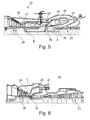
- Fig. 5 shows a section through a gas turbine 22 of the well-known GT24/26 type with sequential combustion comprising first and second combustion chambers 25, 27, first and second burners 24, 26, and first and second turbine sections 28, 28'. Venturi arrangements are located at specific Venturi arrangement locations A and B at the transition between combustion chambers 25, 27 and turbine sections 28, 28'.
- the compressed air is generated in this case by a compressor 23 of the gas turbine 22 and supplied through a plenum 29.
- Fig. 6 shows a section through a gas turbine 30 of the well-known GT13E2 type with an annular combustion chamber 25 and specific Venturi arrangement locations C between the combustor with its combustion chamber 25 and burners 24 and the turbine section 28.
- a compressor 23 supplies compressed air via a plenum 29.
- Fig. 7 shows a section through a different gas turbine 31 (a) with a plurality of individual, circumferentially arranged combustion chambers 25' (b) (can combustor configuration) and specific Venturi arrangement locations D at the transition sections 35 between combustion chambers 25' and a subsequent turbine section 28.
- a compressor 23 supplies compressed air via a plenum 29.
- Fig. 8 shows in a perspective view a gas turbine 32 of the well-known GT11 N2 type with a silo-type combustor with a combustion chamber 34 and burners 33 and specific Venturi arrangement locations E in the transition section 35 between combustion chamber 34 and turbine section 28.
- a compressor 23 supplies compressed air.
- the cooling air (or compressed air) driving the Venturi ejector can be taken from a compressor plenum (29) or cooling air pipes (e.g. for the GT 24/26 type of Fig. 5 compressor exit air or high pressure cooling air can be used to drive the recirculation of the second combustor 26, 27).
- a control valve and/or booster/blower can be arranged to control the cooling air flow and thereby the amount of recirculated hot gas.
- a possible operating concept can for example have a high recirculation rate at low part load (e.g. up to 50 or 60% rel. load) to increase the combustor inlet temperature due to the recirculation of hot flue gas.
- low part load e.g. up to 50 or 60% rel. load
- the recirculation can be increased again to reduce NO x emission due to the reduction of oxygen concentration in the combustor inlet gas with high recirculation rate.
- re-cooled compressed air can be used to drive the Venturi injector.
- the temperature can be controlled to control the recirculation rate.
Landscapes
- Engineering & Computer Science (AREA)
- Chemical & Material Sciences (AREA)
- Combustion & Propulsion (AREA)
- Mechanical Engineering (AREA)
- General Engineering & Computer Science (AREA)
- Life Sciences & Earth Sciences (AREA)
- Sustainable Development (AREA)
- Turbine Rotor Nozzle Sealing (AREA)
Priority Applications (4)
| Application Number | Priority Date | Filing Date | Title |
|---|---|---|---|
| EP14172924.4A EP2957835B1 (fr) | 2014-06-18 | 2014-06-18 | Procédé de recirculation des gaz d'échappement provenant d'une chambre de combustion d'un brûleur d'une turbine à gaz et turbine à gaz pour l'exécution de ce procédé |
| JP2015121004A JP2016003853A (ja) | 2014-06-18 | 2015-06-16 | ガスタービンの燃焼器の燃焼室から排ガスを再循環する方法及び前記方法を行うためのガスタービン |
| US14/741,838 US20150369126A1 (en) | 2014-06-18 | 2015-06-17 | Method for recirculation of exhaust gas from a combustion chamber of a combustor of a gas turbine and gas turbine for doncuting said method |
| CN201510339608.1A CN105276616A (zh) | 2014-06-18 | 2015-06-18 | 用于使排气再循环的方法和用于执行所述方法的燃气涡轮 |
Applications Claiming Priority (1)
| Application Number | Priority Date | Filing Date | Title |
|---|---|---|---|
| EP14172924.4A EP2957835B1 (fr) | 2014-06-18 | 2014-06-18 | Procédé de recirculation des gaz d'échappement provenant d'une chambre de combustion d'un brûleur d'une turbine à gaz et turbine à gaz pour l'exécution de ce procédé |
Publications (2)
| Publication Number | Publication Date |
|---|---|
| EP2957835A1 true EP2957835A1 (fr) | 2015-12-23 |
| EP2957835B1 EP2957835B1 (fr) | 2018-03-21 |
Family
ID=50942610
Family Applications (1)
| Application Number | Title | Priority Date | Filing Date |
|---|---|---|---|
| EP14172924.4A Not-in-force EP2957835B1 (fr) | 2014-06-18 | 2014-06-18 | Procédé de recirculation des gaz d'échappement provenant d'une chambre de combustion d'un brûleur d'une turbine à gaz et turbine à gaz pour l'exécution de ce procédé |
Country Status (4)
| Country | Link |
|---|---|
| US (1) | US20150369126A1 (fr) |
| EP (1) | EP2957835B1 (fr) |
| JP (1) | JP2016003853A (fr) |
| CN (1) | CN105276616A (fr) |
Cited By (1)
| Publication number | Priority date | Publication date | Assignee | Title |
|---|---|---|---|---|
| CN113834080A (zh) * | 2021-09-30 | 2021-12-24 | 湖州市检验检测中心 | 一种用于化工甲醛、木业能源综合利用方法及设备 |
Families Citing this family (13)
| Publication number | Priority date | Publication date | Assignee | Title |
|---|---|---|---|---|
| GB2544520A (en) * | 2015-11-19 | 2017-05-24 | Edwards Ltd | Effluent gas treatment apparatus and method |
| CN105570931B (zh) * | 2015-12-30 | 2017-12-01 | 中国科学院工程热物理研究所 | 一种可引射燃烧器出口流体的燃烧器 |
| KR101931968B1 (ko) * | 2016-12-21 | 2018-12-24 | 두산중공업 주식회사 | 연도 가스 재순환 연소기를 포함하는 터빈. |
| US10316803B2 (en) | 2017-09-25 | 2019-06-11 | Woodward, Inc. | Passive pumping for recirculating exhaust gas |
| US10995705B2 (en) | 2019-02-07 | 2021-05-04 | Woodward, Inc. | Modular exhaust gas recirculation system |
| EP3973160B1 (fr) * | 2019-05-21 | 2023-08-02 | Hyliion Holdings Corp. | Corps d'appareils de chauffage monolithiques |
| US10995706B1 (en) * | 2019-11-22 | 2021-05-04 | Weichai Power Co., Ltd. | Gas mixing device and a natural gas engine |
| CN110822950B (zh) * | 2019-11-22 | 2020-10-27 | 湖北和乐门业有限公司 | 一种余热利用系统及方法 |
| CN213175878U (zh) | 2020-01-08 | 2021-05-11 | 伍德沃德有限公司 | 排气气体再循环混合器和发动机系统 |
| CN112393259A (zh) * | 2020-11-13 | 2021-02-23 | 山东四达工贸股份有限公司 | 酚醛树脂涂布作业中的烘干及废气处理方法 |
| US11174809B1 (en) | 2020-12-15 | 2021-11-16 | Woodward, Inc. | Controlling an internal combustion engine system |
| US11215132B1 (en) | 2020-12-15 | 2022-01-04 | Woodward, Inc. | Controlling an internal combustion engine system |
| CN115977837B (zh) * | 2023-03-17 | 2023-07-18 | 潍柴动力股份有限公司 | 车辆废气再循环管路及设计车辆废气再循环管路的方法 |
Citations (16)
| Publication number | Priority date | Publication date | Assignee | Title |
|---|---|---|---|---|
| US3949548A (en) | 1974-06-13 | 1976-04-13 | Lockwood Jr Hanford N | Gas turbine regeneration system |
| DE3411444A1 (de) | 1984-01-31 | 1985-08-01 | BBC Aktiengesellschaft Brown, Boveri & Cie., Baden, Aargau | Gasturbinenkraftwerk mit luftspeicherung und verfahren zum betrieb desselben |
| US4609342A (en) | 1983-01-10 | 1986-09-02 | Automotive Engine Associates | Abatement of NOx from heterogeneous combustion sources by ultrahomogeneous air-EGR mixing |
| US5351474A (en) | 1991-12-18 | 1994-10-04 | General Electric Company | Combustor external air staging device |
| GB2288011A (en) * | 1994-04-02 | 1995-10-04 | Abb Management Ag | Combustion chamber with premixing burners |
| US5645410A (en) | 1994-11-19 | 1997-07-08 | Asea Brown Boveri Ag | Combustion chamber with multi-stage combustion |
| JPH11304151A (ja) | 1998-04-21 | 1999-11-05 | Mitsubishi Heavy Ind Ltd | 拡散燃焼型ガスタービン |
| EP0985882A1 (fr) * | 1998-09-10 | 2000-03-15 | Asea Brown Boveri AG | Amortissement des vibrations dans des combusteurs |
| US6192688B1 (en) | 1996-05-02 | 2001-02-27 | General Electric Co. | Premixing dry low nox emissions combustor with lean direct injection of gas fule |
| EP1752616A2 (fr) | 2005-03-31 | 2007-02-14 | ALSTOM Technology Ltd | Installation de turbine à gaz |
| WO2008155242A1 (fr) | 2007-06-19 | 2008-12-24 | Alstom Technology Ltd | Installation de turbine à gaz avec recirculation des gaz d'échappement |
| EP2211109A1 (fr) | 2009-01-23 | 2010-07-28 | Alstom Technology Ltd | Brûleur de turbine à gaz et procédé pour mélanger un carburant avec un flux gazeux |
| WO2011037646A1 (fr) | 2009-09-24 | 2011-03-31 | Siemens Energy, Inc. | Ensemble buse à combustible utilisé dans un appareil de combustion de moteur de turbine à gaz |
| WO2011054757A2 (fr) | 2009-11-07 | 2011-05-12 | Alstom Technology Ltd | Système d'injection pour brûleur de réchauffage avec lances à combustible |
| WO2011054766A2 (fr) | 2009-11-07 | 2011-05-12 | Alstom Technology Ltd | Système d'injection de brûleur de postcombustion |
| US20130340404A1 (en) * | 2012-06-22 | 2013-12-26 | General Electric Company | Hot egr driven by turbomachinery |
Family Cites Families (14)
| Publication number | Priority date | Publication date | Assignee | Title |
|---|---|---|---|---|
| US3918262A (en) * | 1974-09-05 | 1975-11-11 | Ford Motor Co | Hot exhaust gas recirculating system for a stirling engine |
| US5135387A (en) * | 1989-10-19 | 1992-08-04 | It-Mcgill Environmental Systems, Inc. | Nitrogen oxide control using internally recirculated flue gas |
| US5240409A (en) * | 1992-04-10 | 1993-08-31 | Institute Of Gas Technology | Premixed fuel/air burners |
| US5542840A (en) * | 1994-01-26 | 1996-08-06 | Zeeco Inc. | Burner for combusting gas and/or liquid fuel with low NOx production |
| AU681271B2 (en) * | 1994-06-07 | 1997-08-21 | Westinghouse Electric Corporation | Method and apparatus for sequentially staged combustion using a catalyst |
| US6925809B2 (en) * | 1999-02-26 | 2005-08-09 | R. Jan Mowill | Gas turbine engine fuel/air premixers with variable geometry exit and method for controlling exit velocities |
| US20020139119A1 (en) * | 2001-04-02 | 2002-10-03 | Touchton George L. | Combustor with inlet temperature control |
| JP2005140358A (ja) * | 2003-11-05 | 2005-06-02 | Nissan Motor Co Ltd | 燃焼器 |
| DE102006009153A1 (de) * | 2006-02-24 | 2007-08-30 | Mahle International Gmbh | Abgasrückführeinrichtung |
| DE102006000174B9 (de) * | 2006-04-13 | 2009-04-16 | Honeywell Technologies Sarl | Öl-Vormischbrenner und Betriebsverfahren dafür |
| US8397482B2 (en) * | 2008-05-15 | 2013-03-19 | General Electric Company | Dry 3-way catalytic reduction of gas turbine NOx |
| US8904802B2 (en) * | 2011-06-30 | 2014-12-09 | General Electric Company | Turbomachine combustor assembly including a vortex modification system |
| US9260974B2 (en) * | 2011-12-16 | 2016-02-16 | General Electric Company | System and method for active clearance control |
| US8707673B1 (en) * | 2013-01-04 | 2014-04-29 | General Electric Company | Articulated transition duct in turbomachine |
-
2014
- 2014-06-18 EP EP14172924.4A patent/EP2957835B1/fr not_active Not-in-force
-
2015
- 2015-06-16 JP JP2015121004A patent/JP2016003853A/ja active Pending
- 2015-06-17 US US14/741,838 patent/US20150369126A1/en not_active Abandoned
- 2015-06-18 CN CN201510339608.1A patent/CN105276616A/zh active Pending
Patent Citations (16)
| Publication number | Priority date | Publication date | Assignee | Title |
|---|---|---|---|---|
| US3949548A (en) | 1974-06-13 | 1976-04-13 | Lockwood Jr Hanford N | Gas turbine regeneration system |
| US4609342A (en) | 1983-01-10 | 1986-09-02 | Automotive Engine Associates | Abatement of NOx from heterogeneous combustion sources by ultrahomogeneous air-EGR mixing |
| DE3411444A1 (de) | 1984-01-31 | 1985-08-01 | BBC Aktiengesellschaft Brown, Boveri & Cie., Baden, Aargau | Gasturbinenkraftwerk mit luftspeicherung und verfahren zum betrieb desselben |
| US5351474A (en) | 1991-12-18 | 1994-10-04 | General Electric Company | Combustor external air staging device |
| GB2288011A (en) * | 1994-04-02 | 1995-10-04 | Abb Management Ag | Combustion chamber with premixing burners |
| US5645410A (en) | 1994-11-19 | 1997-07-08 | Asea Brown Boveri Ag | Combustion chamber with multi-stage combustion |
| US6192688B1 (en) | 1996-05-02 | 2001-02-27 | General Electric Co. | Premixing dry low nox emissions combustor with lean direct injection of gas fule |
| JPH11304151A (ja) | 1998-04-21 | 1999-11-05 | Mitsubishi Heavy Ind Ltd | 拡散燃焼型ガスタービン |
| EP0985882A1 (fr) * | 1998-09-10 | 2000-03-15 | Asea Brown Boveri AG | Amortissement des vibrations dans des combusteurs |
| EP1752616A2 (fr) | 2005-03-31 | 2007-02-14 | ALSTOM Technology Ltd | Installation de turbine à gaz |
| WO2008155242A1 (fr) | 2007-06-19 | 2008-12-24 | Alstom Technology Ltd | Installation de turbine à gaz avec recirculation des gaz d'échappement |
| EP2211109A1 (fr) | 2009-01-23 | 2010-07-28 | Alstom Technology Ltd | Brûleur de turbine à gaz et procédé pour mélanger un carburant avec un flux gazeux |
| WO2011037646A1 (fr) | 2009-09-24 | 2011-03-31 | Siemens Energy, Inc. | Ensemble buse à combustible utilisé dans un appareil de combustion de moteur de turbine à gaz |
| WO2011054757A2 (fr) | 2009-11-07 | 2011-05-12 | Alstom Technology Ltd | Système d'injection pour brûleur de réchauffage avec lances à combustible |
| WO2011054766A2 (fr) | 2009-11-07 | 2011-05-12 | Alstom Technology Ltd | Système d'injection de brûleur de postcombustion |
| US20130340404A1 (en) * | 2012-06-22 | 2013-12-26 | General Electric Company | Hot egr driven by turbomachinery |
Cited By (1)
| Publication number | Priority date | Publication date | Assignee | Title |
|---|---|---|---|---|
| CN113834080A (zh) * | 2021-09-30 | 2021-12-24 | 湖州市检验检测中心 | 一种用于化工甲醛、木业能源综合利用方法及设备 |
Also Published As
| Publication number | Publication date |
|---|---|
| US20150369126A1 (en) | 2015-12-24 |
| CN105276616A (zh) | 2016-01-27 |
| JP2016003853A (ja) | 2016-01-12 |
| EP2957835B1 (fr) | 2018-03-21 |
Similar Documents
| Publication | Publication Date | Title |
|---|---|---|
| EP2957835B1 (fr) | Procédé de recirculation des gaz d'échappement provenant d'une chambre de combustion d'un brûleur d'une turbine à gaz et turbine à gaz pour l'exécution de ce procédé | |
| EP2912381B1 (fr) | Combustion séquentielle avec mélangeur de gaz d'appoint | |
| US10634357B2 (en) | Sequential combustion with dilution gas mixer | |
| US8281601B2 (en) | Systems and methods for reintroducing gas turbine combustion bypass flow | |
| JP6138584B2 (ja) | タービンエンジンに使用するための燃料注入組立体及びそれを組み立てる方法 | |
| KR101774093B1 (ko) | 가스 터빈 엔진에서 사용되는 스테이지가 형성되고 접선방향으로 형성된 연료-공기 노즐을 가진 캔-애뉼러형 연소실 | |
| JP6779651B2 (ja) | 燃料ノズルを有するシステムおよび方法 | |
| EP2894405B1 (fr) | Dispositif à combustion séquentielle avec un gaz de dilution | |
| JP2008215646A (ja) | 燃料ノズル装置、ガスタービンおよび燃料ノズル装置の制御方法 | |
| RU2570480C2 (ru) | Способ смешивания разбавляющего воздуха в системе последовательного сгорания газовой турбины | |
| US10215417B2 (en) | Sequential combustor arrangement with a mixer | |
| JP2018508735A (ja) | 排気再循環を有するガスタービンエンジン内の高い体積酸化剤流量のためのシステム及び方法 | |
| JP2008274774A (ja) | ガスタービン燃焼器およびガスタービン | |
| US10968781B2 (en) | System and method for cooling discharge flow | |
| CN106468449B (zh) | 带有用于稀释的冷却气体的连续燃烧布置 | |
| EP2828581B1 (fr) | Dispositif de combustion |
Legal Events
| Date | Code | Title | Description |
|---|---|---|---|
| PUAI | Public reference made under article 153(3) epc to a published international application that has entered the european phase |
Free format text: ORIGINAL CODE: 0009012 |
|
| 17P | Request for examination filed |
Effective date: 20140618 |
|
| AK | Designated contracting states |
Kind code of ref document: A1 Designated state(s): AL AT BE BG CH CY CZ DE DK EE ES FI FR GB GR HR HU IE IS IT LI LT LU LV MC MK MT NL NO PL PT RO RS SE SI SK SM TR |
|
| AX | Request for extension of the european patent |
Extension state: BA ME |
|
| RAP1 | Party data changed (applicant data changed or rights of an application transferred) |
Owner name: GENERAL ELECTRIC TECHNOLOGY GMBH |
|
| RAP1 | Party data changed (applicant data changed or rights of an application transferred) |
Owner name: ANSALDO ENERGIA SWITZERLAND AG |
|
| GRAP | Despatch of communication of intention to grant a patent |
Free format text: ORIGINAL CODE: EPIDOSNIGR1 |
|
| INTG | Intention to grant announced |
Effective date: 20170922 |
|
| GRAS | Grant fee paid |
Free format text: ORIGINAL CODE: EPIDOSNIGR3 |
|
| GRAA | (expected) grant |
Free format text: ORIGINAL CODE: 0009210 |
|
| AK | Designated contracting states |
Kind code of ref document: B1 Designated state(s): AL AT BE BG CH CY CZ DE DK EE ES FI FR GB GR HR HU IE IS IT LI LT LU LV MC MK MT NL NO PL PT RO RS SE SI SK SM TR |
|
| REG | Reference to a national code |
Ref country code: GB Ref legal event code: FG4D |
|
| REG | Reference to a national code |
Ref country code: CH Ref legal event code: EP |
|
| REG | Reference to a national code |
Ref country code: AT Ref legal event code: REF Ref document number: 981515 Country of ref document: AT Kind code of ref document: T Effective date: 20180415 |
|
| REG | Reference to a national code |
Ref country code: IE Ref legal event code: FG4D |
|
| REG | Reference to a national code |
Ref country code: DE Ref legal event code: R096 Ref document number: 602014022517 Country of ref document: DE |
|
| REG | Reference to a national code |
Ref country code: NL Ref legal event code: MP Effective date: 20180321 |
|
| PG25 | Lapsed in a contracting state [announced via postgrant information from national office to epo] |
Ref country code: HR Free format text: LAPSE BECAUSE OF FAILURE TO SUBMIT A TRANSLATION OF THE DESCRIPTION OR TO PAY THE FEE WITHIN THE PRESCRIBED TIME-LIMIT Effective date: 20180321 Ref country code: CY Free format text: LAPSE BECAUSE OF FAILURE TO SUBMIT A TRANSLATION OF THE DESCRIPTION OR TO PAY THE FEE WITHIN THE PRESCRIBED TIME-LIMIT Effective date: 20180321 Ref country code: LT Free format text: LAPSE BECAUSE OF FAILURE TO SUBMIT A TRANSLATION OF THE DESCRIPTION OR TO PAY THE FEE WITHIN THE PRESCRIBED TIME-LIMIT Effective date: 20180321 Ref country code: NO Free format text: LAPSE BECAUSE OF FAILURE TO SUBMIT A TRANSLATION OF THE DESCRIPTION OR TO PAY THE FEE WITHIN THE PRESCRIBED TIME-LIMIT Effective date: 20180621 Ref country code: FI Free format text: LAPSE BECAUSE OF FAILURE TO SUBMIT A TRANSLATION OF THE DESCRIPTION OR TO PAY THE FEE WITHIN THE PRESCRIBED TIME-LIMIT Effective date: 20180321 |
|
| PGFP | Annual fee paid to national office [announced via postgrant information from national office to epo] |
Ref country code: DE Payment date: 20180625 Year of fee payment: 5 |
|
| REG | Reference to a national code |
Ref country code: LT Ref legal event code: MG4D |
|
| REG | Reference to a national code |
Ref country code: AT Ref legal event code: MK05 Ref document number: 981515 Country of ref document: AT Kind code of ref document: T Effective date: 20180321 |
|
| PG25 | Lapsed in a contracting state [announced via postgrant information from national office to epo] |
Ref country code: LV Free format text: LAPSE BECAUSE OF FAILURE TO SUBMIT A TRANSLATION OF THE DESCRIPTION OR TO PAY THE FEE WITHIN THE PRESCRIBED TIME-LIMIT Effective date: 20180321 Ref country code: BG Free format text: LAPSE BECAUSE OF FAILURE TO SUBMIT A TRANSLATION OF THE DESCRIPTION OR TO PAY THE FEE WITHIN THE PRESCRIBED TIME-LIMIT Effective date: 20180621 Ref country code: GR Free format text: LAPSE BECAUSE OF FAILURE TO SUBMIT A TRANSLATION OF THE DESCRIPTION OR TO PAY THE FEE WITHIN THE PRESCRIBED TIME-LIMIT Effective date: 20180622 Ref country code: RS Free format text: LAPSE BECAUSE OF FAILURE TO SUBMIT A TRANSLATION OF THE DESCRIPTION OR TO PAY THE FEE WITHIN THE PRESCRIBED TIME-LIMIT Effective date: 20180321 Ref country code: SE Free format text: LAPSE BECAUSE OF FAILURE TO SUBMIT A TRANSLATION OF THE DESCRIPTION OR TO PAY THE FEE WITHIN THE PRESCRIBED TIME-LIMIT Effective date: 20180321 |
|
| PG25 | Lapsed in a contracting state [announced via postgrant information from national office to epo] |
Ref country code: AL Free format text: LAPSE BECAUSE OF FAILURE TO SUBMIT A TRANSLATION OF THE DESCRIPTION OR TO PAY THE FEE WITHIN THE PRESCRIBED TIME-LIMIT Effective date: 20180321 Ref country code: RO Free format text: LAPSE BECAUSE OF FAILURE TO SUBMIT A TRANSLATION OF THE DESCRIPTION OR TO PAY THE FEE WITHIN THE PRESCRIBED TIME-LIMIT Effective date: 20180321 Ref country code: ES Free format text: LAPSE BECAUSE OF FAILURE TO SUBMIT A TRANSLATION OF THE DESCRIPTION OR TO PAY THE FEE WITHIN THE PRESCRIBED TIME-LIMIT Effective date: 20180321 Ref country code: PL Free format text: LAPSE BECAUSE OF FAILURE TO SUBMIT A TRANSLATION OF THE DESCRIPTION OR TO PAY THE FEE WITHIN THE PRESCRIBED TIME-LIMIT Effective date: 20180321 Ref country code: NL Free format text: LAPSE BECAUSE OF FAILURE TO SUBMIT A TRANSLATION OF THE DESCRIPTION OR TO PAY THE FEE WITHIN THE PRESCRIBED TIME-LIMIT Effective date: 20180321 Ref country code: IT Free format text: LAPSE BECAUSE OF FAILURE TO SUBMIT A TRANSLATION OF THE DESCRIPTION OR TO PAY THE FEE WITHIN THE PRESCRIBED TIME-LIMIT Effective date: 20180321 Ref country code: EE Free format text: LAPSE BECAUSE OF FAILURE TO SUBMIT A TRANSLATION OF THE DESCRIPTION OR TO PAY THE FEE WITHIN THE PRESCRIBED TIME-LIMIT Effective date: 20180321 |
|
| PG25 | Lapsed in a contracting state [announced via postgrant information from national office to epo] |
Ref country code: SM Free format text: LAPSE BECAUSE OF FAILURE TO SUBMIT A TRANSLATION OF THE DESCRIPTION OR TO PAY THE FEE WITHIN THE PRESCRIBED TIME-LIMIT Effective date: 20180321 Ref country code: AT Free format text: LAPSE BECAUSE OF FAILURE TO SUBMIT A TRANSLATION OF THE DESCRIPTION OR TO PAY THE FEE WITHIN THE PRESCRIBED TIME-LIMIT Effective date: 20180321 Ref country code: CZ Free format text: LAPSE BECAUSE OF FAILURE TO SUBMIT A TRANSLATION OF THE DESCRIPTION OR TO PAY THE FEE WITHIN THE PRESCRIBED TIME-LIMIT Effective date: 20180321 Ref country code: SK Free format text: LAPSE BECAUSE OF FAILURE TO SUBMIT A TRANSLATION OF THE DESCRIPTION OR TO PAY THE FEE WITHIN THE PRESCRIBED TIME-LIMIT Effective date: 20180321 |
|
| PG25 | Lapsed in a contracting state [announced via postgrant information from national office to epo] |
Ref country code: PT Free format text: LAPSE BECAUSE OF FAILURE TO SUBMIT A TRANSLATION OF THE DESCRIPTION OR TO PAY THE FEE WITHIN THE PRESCRIBED TIME-LIMIT Effective date: 20180723 |
|
| REG | Reference to a national code |
Ref country code: DE Ref legal event code: R097 Ref document number: 602014022517 Country of ref document: DE |
|
| PLBE | No opposition filed within time limit |
Free format text: ORIGINAL CODE: 0009261 |
|
| STAA | Information on the status of an ep patent application or granted ep patent |
Free format text: STATUS: NO OPPOSITION FILED WITHIN TIME LIMIT |
|
| PG25 | Lapsed in a contracting state [announced via postgrant information from national office to epo] |
Ref country code: DK Free format text: LAPSE BECAUSE OF FAILURE TO SUBMIT A TRANSLATION OF THE DESCRIPTION OR TO PAY THE FEE WITHIN THE PRESCRIBED TIME-LIMIT Effective date: 20180321 |
|
| REG | Reference to a national code |
Ref country code: CH Ref legal event code: PL |
|
| 26N | No opposition filed |
Effective date: 20190102 |
|
| GBPC | Gb: european patent ceased through non-payment of renewal fee |
Effective date: 20180621 |
|
| REG | Reference to a national code |
Ref country code: BE Ref legal event code: MM Effective date: 20180630 |
|
| REG | Reference to a national code |
Ref country code: IE Ref legal event code: MM4A |
|
| PG25 | Lapsed in a contracting state [announced via postgrant information from national office to epo] |
Ref country code: LU Free format text: LAPSE BECAUSE OF NON-PAYMENT OF DUE FEES Effective date: 20180618 Ref country code: MC Free format text: LAPSE BECAUSE OF FAILURE TO SUBMIT A TRANSLATION OF THE DESCRIPTION OR TO PAY THE FEE WITHIN THE PRESCRIBED TIME-LIMIT Effective date: 20180321 |
|
| PG25 | Lapsed in a contracting state [announced via postgrant information from national office to epo] |
Ref country code: LI Free format text: LAPSE BECAUSE OF NON-PAYMENT OF DUE FEES Effective date: 20180630 Ref country code: GB Free format text: LAPSE BECAUSE OF NON-PAYMENT OF DUE FEES Effective date: 20180621 Ref country code: FR Free format text: LAPSE BECAUSE OF NON-PAYMENT OF DUE FEES Effective date: 20180630 Ref country code: CH Free format text: LAPSE BECAUSE OF NON-PAYMENT OF DUE FEES Effective date: 20180630 Ref country code: IE Free format text: LAPSE BECAUSE OF NON-PAYMENT OF DUE FEES Effective date: 20180618 |
|
| PG25 | Lapsed in a contracting state [announced via postgrant information from national office to epo] |
Ref country code: BE Free format text: LAPSE BECAUSE OF NON-PAYMENT OF DUE FEES Effective date: 20180630 Ref country code: SI Free format text: LAPSE BECAUSE OF FAILURE TO SUBMIT A TRANSLATION OF THE DESCRIPTION OR TO PAY THE FEE WITHIN THE PRESCRIBED TIME-LIMIT Effective date: 20180321 |
|
| REG | Reference to a national code |
Ref country code: DE Ref legal event code: R119 Ref document number: 602014022517 Country of ref document: DE |
|
| PG25 | Lapsed in a contracting state [announced via postgrant information from national office to epo] |
Ref country code: MT Free format text: LAPSE BECAUSE OF NON-PAYMENT OF DUE FEES Effective date: 20180618 |
|
| PG25 | Lapsed in a contracting state [announced via postgrant information from national office to epo] |
Ref country code: TR Free format text: LAPSE BECAUSE OF FAILURE TO SUBMIT A TRANSLATION OF THE DESCRIPTION OR TO PAY THE FEE WITHIN THE PRESCRIBED TIME-LIMIT Effective date: 20180321 |
|
| PG25 | Lapsed in a contracting state [announced via postgrant information from national office to epo] |
Ref country code: DE Free format text: LAPSE BECAUSE OF NON-PAYMENT OF DUE FEES Effective date: 20200101 |
|
| PG25 | Lapsed in a contracting state [announced via postgrant information from national office to epo] |
Ref country code: HU Free format text: LAPSE BECAUSE OF FAILURE TO SUBMIT A TRANSLATION OF THE DESCRIPTION OR TO PAY THE FEE WITHIN THE PRESCRIBED TIME-LIMIT; INVALID AB INITIO Effective date: 20140618 Ref country code: MK Free format text: LAPSE BECAUSE OF NON-PAYMENT OF DUE FEES Effective date: 20180321 |
|
| PG25 | Lapsed in a contracting state [announced via postgrant information from national office to epo] |
Ref country code: IS Free format text: LAPSE BECAUSE OF FAILURE TO SUBMIT A TRANSLATION OF THE DESCRIPTION OR TO PAY THE FEE WITHIN THE PRESCRIBED TIME-LIMIT Effective date: 20180721 |