EP2957741B1 - Vorrichtung zur energierückgewinnung über einen rankine-kreisprozess - Google Patents
Vorrichtung zur energierückgewinnung über einen rankine-kreisprozess Download PDFInfo
- Publication number
- EP2957741B1 EP2957741B1 EP15169813.1A EP15169813A EP2957741B1 EP 2957741 B1 EP2957741 B1 EP 2957741B1 EP 15169813 A EP15169813 A EP 15169813A EP 2957741 B1 EP2957741 B1 EP 2957741B1
- Authority
- EP
- European Patent Office
- Prior art keywords
- fluid
- expansion member
- valve
- passage
- loop
- Prior art date
- Legal status (The legal status is an assumption and is not a legal conclusion. Google has not performed a legal analysis and makes no representation as to the accuracy of the status listed.)
- Active
Links
Images

Classifications
-
- F—MECHANICAL ENGINEERING; LIGHTING; HEATING; WEAPONS; BLASTING
- F01—MACHINES OR ENGINES IN GENERAL; ENGINE PLANTS IN GENERAL; STEAM ENGINES
- F01N—GAS-FLOW SILENCERS OR EXHAUST APPARATUS FOR MACHINES OR ENGINES IN GENERAL; GAS-FLOW SILENCERS OR EXHAUST APPARATUS FOR INTERNAL-COMBUSTION ENGINES
- F01N5/00—Exhaust or silencing apparatus combined or associated with devices profiting by exhaust energy
- F01N5/02—Exhaust or silencing apparatus combined or associated with devices profiting by exhaust energy the devices using heat
-
- F—MECHANICAL ENGINEERING; LIGHTING; HEATING; WEAPONS; BLASTING
- F01—MACHINES OR ENGINES IN GENERAL; ENGINE PLANTS IN GENERAL; STEAM ENGINES
- F01K—STEAM ENGINE PLANTS; STEAM ACCUMULATORS; ENGINE PLANTS NOT OTHERWISE PROVIDED FOR; ENGINES USING SPECIAL WORKING FLUIDS OR CYCLES
- F01K5/00—Plants characterised by use of means for storing steam in an alkali to increase steam pressure, e.g. of Honigmann or Koenemann type
-
- F—MECHANICAL ENGINEERING; LIGHTING; HEATING; WEAPONS; BLASTING
- F01—MACHINES OR ENGINES IN GENERAL; ENGINE PLANTS IN GENERAL; STEAM ENGINES
- F01N—GAS-FLOW SILENCERS OR EXHAUST APPARATUS FOR MACHINES OR ENGINES IN GENERAL; GAS-FLOW SILENCERS OR EXHAUST APPARATUS FOR INTERNAL-COMBUSTION ENGINES
- F01N2240/00—Combination or association of two or more different exhaust treating devices, or of at least one such device with an auxiliary device, not covered by indexing codes F01N2230/00 or F01N2250/00, one of the devices being
- F01N2240/02—Combination or association of two or more different exhaust treating devices, or of at least one such device with an auxiliary device, not covered by indexing codes F01N2230/00 or F01N2250/00, one of the devices being a heat exchanger
-
- Y—GENERAL TAGGING OF NEW TECHNOLOGICAL DEVELOPMENTS; GENERAL TAGGING OF CROSS-SECTIONAL TECHNOLOGIES SPANNING OVER SEVERAL SECTIONS OF THE IPC; TECHNICAL SUBJECTS COVERED BY FORMER USPC CROSS-REFERENCE ART COLLECTIONS [XRACs] AND DIGESTS
- Y02—TECHNOLOGIES OR APPLICATIONS FOR MITIGATION OR ADAPTATION AGAINST CLIMATE CHANGE
- Y02T—CLIMATE CHANGE MITIGATION TECHNOLOGIES RELATED TO TRANSPORTATION
- Y02T10/00—Road transport of goods or passengers
- Y02T10/10—Internal combustion engine [ICE] based vehicles
- Y02T10/12—Improving ICE efficiencies
Definitions
- the present invention relates to a Rankine loop energy recovery device.
- the invention also relates to an expansion member for a Rankine loop energy recovery device and a vehicle equipped with such a device.
- the problem underlying the invention is to overcome the problems of the prior art and to provide an exhaust energy recovery device suitable for life situations where power to the line exhaust may be insufficient, while remaining compact.
- control means comprise means for determining information representative of the power available at the hot source and control means adapted to control the blocking means based on this representative information acquired.
- the device of the invention comprises an electric generator cooperating with the transmission means for converting the mechanical energy produced by the expansion member into electrical energy, the electric generator acting as locking means.
- the branch circuit is distinct from the expansion member.
- the branch circuit is integrated with the expansion member.
- the inner passage comprises a phase change material.
- the expansion member is a spiro-orbital type expansion member.
- the invention also relates to a motor vehicle comprising an internal combustion engine connected to an exhaust line, characterized in that it comprises a Rankine loop energy recovery device of the invention in thermal contact with the line. exhaust as a hot source.
- the invention also relates to a motor vehicle comprising an internal combustion engine connected to an exhaust line, characterized in that it comprises a Rankine loop energy recovery device in its variant where the branch circuit is integrated the detent member coupled to the exhaust line as a hot source and comprising an expansion member of the invention.
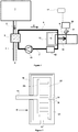
- a motor vehicle is equipped with an internal combustion engine 1 for its setting in motion.
- the internal combustion engine 1 produces exhaust gases 2 which are discharged to an external environment 3 via an exhaust line 4.
- thermodynamic loop energy recovery device in thermal contact with the exhaust line 4 as a hot source.
- the Rankine loop energy recovery device comprises a heat exchange loop 6 inside which a working fluid 7 circulates.
- a heat exchanger 5 is disposed in the heat exchange loop 6, in thermal contact with the exhaust line 4 as a hot source so as to capture the calories conveyed by the exhaust gases 2 to transfer them to the working fluid 7 .
- the heat exchanger 5 intended to transfer heat from the exhaust line 4 to the working fluid 7 preferably constitutes an evaporator for the working fluid 7, such that the latter changes from a liquid state to a vapor state. inside the heat exchanger 5.
- the fluid 7 is in the high-pressure vapor state between the heat exchanger 5 and the spiro-orbital expansion element 9, that the fluid 7 is in the low-pressure vapor state between 9 and spiro-orbital expansion element and the condenser 12, that the fluid 7 is in the low pressure liquid state between the condenser 12 and the pump 13, and that the fluid 7 is in the state of high-pressure liquid between the pump 13 and the heat exchanger 5.
- the working fluid 7 may for example be water.
- the non-return valve 16 is a passive valve in the sense that it is not directly controlled by an external source of energy, electrical for example.
- the non-return valve 16 is normally closed.
- the branch circuit is distinct from the expansion member 9. It consists, for example, of a line external to the expansion member 9.
- the energy recovery device further comprises an electric generator 14 cooperating with the transmission means formed by the shaft 11 to convert the mechanical energy produced by the expansion member 9 in electrical energy.
- the energy recovery device further comprises control means 17 of the electric generator 14.
- the control means 17 may be in the form of a computer equipped with electronics capable of regulating the speed of rotation of the generator 14.
- the electric generator 14 thus acts as means for blocking the transmission means.
- the control means 17 include means for determining information representative of the power available at the hot source.
- the control means 17 also include means for controlling the electric generator 14 according to this acquired information.
- the control means 17 drives the electric generator 14 so as to prevent it from rotating.
- the rotation of the electric generator 14 is blocked, the rotation of the expansion member 9 is also blocked and the pressure of the fluid 7 increases in the loop 6 upstream of the expansion member 9 to exert on the valve 16 the determined calibration effort beyond which the valve 16 opens to allow the passage of the fluid 7 in the branch circuit 15.
- the control means 14 authorizes and controls the generator 14 so as to allow rotation thereof.
- the rotation of the electric generator 14 is allowed, the rotation of the expansion member 9 is also and the pressure of the fluid 7 in the loop 6 upstream of the expansion member 9 decreases until s 'exerts on the valve 16 a force less than the effort of the determined setting effort.
- the valve 16 then closes to prevent the passage of fluid in the bypass circuit.
- control means 17 also comprise means for determining the pressure and / or the temperature of the working fluid 7.
- control means are adapted to also take into account the pressure and the determined temperature of the fluid 7, in the control of the electric generator 14.
- the non-return valve 16 allows the working fluid 7 to bypass the expansion member 9 when the fluid 7 has not yet reached the conditions under which it can be operated.
- expansion member 9 ' for a Rankine loop energy recovery device in which the branch circuit is integrated with the trigger member 9'.
- the expansion member 9 ' is here a spiro-orbital type member, it therefore comprises a fixed turn 22 and a mobile coil 23 to which is connected the power transmission shaft 11.
- the fixed turn 22 is engaged in the mobile turn 23, the mobile turn 23 being movable relative to the fixed turn 22.
- the detent 9 comprises a casing 18 having an inlet 19 and a fluid outlet 20 7 work.
- the casing 18 comprises an internal passage 21 arranged in the thickness of the casing 18. This internal passage 21 connects the inlet 19 to the outlet 20 of fluid 7 working.
- the internal passage 21 acts as a bypass circuit.
- the passive non-return valve 16 is disposed in the internal passage 21.
- the figure 3 has two check valves 16, but one can suffice.
- the non-return valve comprises a closure element 24 of the internal passage intended to seal the inlet 19 of the internal passage 21, a return spring 25, whose dimensioning makes it possible to adjust the tare effort.
- the spring bears on the closure member 24 on one side and on a support 26 serving as a stop for the return spring 25.
- the support may comprise an orifice 27 for the passage of the fluid in the internal passage 21.
- the energy recovery device presented to the figure 1 differs in that the external bypass circuit 15 and its non-return valve 16 is replaced by the internal passage 21 equipped with the non-return valve 16.
- Such an embodiment makes it possible to reduce the bulk of the energy recovery device.
- the inner passage 21 may comprise a phase change material, which may be porous, for storing heat from the working fluid as it circulates through the internal passage 21; that is, when the shaft 11 is locked in rotation. This improves the energy efficiency of the expansion member 9 ', because it will suffer less heat losses.
- the relaxation member for a Rankine loop recovery device may be of the piston, screw, centrifugal turbine or axial turbine type.
- the blocking means of the transmission means may be other than an electric generator.
- the blocking means may be in the form of friction braking means.
Landscapes
- Engineering & Computer Science (AREA)
- Chemical & Material Sciences (AREA)
- Combustion & Propulsion (AREA)
- Mechanical Engineering (AREA)
- General Engineering & Computer Science (AREA)
- Engine Equipment That Uses Special Cycles (AREA)
Claims (10)
- Vorrichtung zur Energierückgewinnung über einen Rankine-Kreisprozess, der Folgendes umfasst:- eine Wärmeaustauschschleife (6) mit einer Wärmequelle, in der ein Arbeitsfluid (7) zirkuliert,- ein Spannungsorgan (9), das in der Schleife (6) angeordnet ist, das fähig ist, die Energie, die von dem Entspannen des Fluids (7) stammt, in mechanische Energie umzuwandeln,- einen Fluidabzweigungskreislauf (15), der die stromaufwärtige Seite des Entspannungsorgans (9) mit der stromabwärtigen Seite des Entspannungsamts (9) verbindet,- Mittel zum Übertragen der mechanischen Energie, die von dem Entspannungsorgan (9) erzeugt wird,Vorrichtung dadurch gekennzeichnet, dass sie außerdem Folgendes umfasst:- Blockierungsmittel der Übertragungsmittel,- Steuermittel (17) der Blockierungsmittel,- ein passives Rückschlagventil (16), das auf eine bestimmte Einstellungskraft eingestellt und in dem Fluidabzweigungskreislauf (15) angeordnet ist,- wobei die Steuermittel und die Klappe (16) konzipiert sind, um derart zusammenzuwirken, dass,• wenn die an der Wärmequelle verfügbare Leistung niedriger ist als ein vorbestimmter Leistungsschwellenwert, die Steuermittel (17) die Übertragungsmittel blockieren, damit der Druck des Fluids (7) in der Schleife (6) zunimmt, bis auf die Klappe (16) eine Kraft ausgeübt wird, die größer ist als die bestimmte Einstellungskraft, wobei sich die Klappe (16) öffnet, um das Durchgehen des Fluids (7) in den Fluidabzweigungskreislauf (15) zu gestatten.• wenn die Leistung, die an der Wärmequelle verfügbar ist, größer ist als der vorbestimmte Leistungsschwellenwert, die Steuermittel (17) die Übertragungsmittel nicht blockieren, damit der Druck des Fluids (7) in der Schleife (6) abnimmt, bis auf die Klappe (16) eine Kraft des Fluids (7) auf der Klappe (16) ausgeübt wird, die niedriger ist als die Einstellungskraft, wobei sich die Klappe (16) daher schließt, um die Passage des Fluids (7) in den Fluidabzweigungskreislauf (15) zu verhindern.
- Vorrichtung nach Anspruch 1, dadurch gekennzeichnet, dass die Steuermittel (17) Mittel zum Bestimmen einer Information umfassen, die für die Leistung repräsentativ ist, die an der Wärmequelle verfügbar ist, und Mittel zum Steuern, die angepasst sind, um die Blockierungsmittel in Abhängigkeit von dieser erfassten repräsentativen Information zu steuern.
- Vorrichtung nach Anspruch 1 oder 2, dadurch gekennzeichnet, dass sie einen Stromerzeuger (14) umfasst, der mit den Übertragungsmitteln zusammenwirkt, um die von dem Entspannungsorgan (9) erzeugte mechanische Energie in elektrische Energie umzuwandeln, wobei der Stromerzeuger (14) Blockierungsmittel bildet.
- Vorrichtung nach einem der Ansprüche 1 bis 3, dadurch gekennzeichnet, dass der Fluidabzweigungskreislauf (15) von dem Entspannungsorgan (9) getrennt ist.
- Vorrichtung nach einem der Ansprüche 1 bis 3, dadurch gekennzeichnet, dass der Abzweigungskreislauf in das Entspannungsorgan (9') integriert ist.
- Entspannungsorgan (9') für eine Energierückgewinnungsvorrichtung über einen Rankine-Kreisprozess nach Anspruch 5, das ein Gehäuse (18) umfasst, wobei das Gehäuse einen Eingang (19) und einen Ausgang (20) von Arbeitsfluid (7) umfasst,
Entspannungsorgan (9') dadurch gekennzeichnet, dass das Gehäuse (18) Folgendes umfasst:- eine interne Passage (21), die in der Stärke des Gehäuses (18) eingerichtet ist und den Eingang (19) mit dem Ausgang (20) von Arbeitsfluid verbindet, die dazu bestimmt ist, als Abzweigkreislauf zu dienen,- wobei das passive Rückschlagventil (16), das auf eine bestimmte Einstellungskraft eingestellt ist, in der internen Passage (21) derart angeordnet ist, dass:• wenn die Kraft des Fluids (7) auf dem Ventil (16) niedriger ist als die Einstellungskraft, das Ventil (16) geschlossen ist, um das Durchgehen des Fluids (7) in der internen Passage (21) zu verhindern,• wenn die Kraft des Fluids (7) auf dem Ventil (16) größer ist als die Einstellungskraft, das Ventil (16) offen ist, um das Durchgehen des Fluids (7) in der internen Passage (21) zu gestatten. - Entspannungsorgan (9') nach Anspruch 6, dadurch gekennzeichnet, dass die interne Passage (21) ein Phasenwechselmaterial umfasst.
- Entspannungsorgan (9') nach Anspruch 6 oder Anspruch 7, dadurch gekennzeichnet, dass es sich um ein Entspannungsorgan des Scroll-Typs handelt.
- Kraftfahrzeug, das eine Brennkraftmaschine umfasst, die mit einem Auspuffstrang (4) verbunden ist, dadurch gekennzeichnet, dass es eine Energierückgewinnungsvorrichtung über einen Rankine-Kreisprozess nach einem der Ansprüche 1 bis 4 in Wärmeberührung mit dem Abgasstrang (4) als Wärmequelle umfasst.
- Kraftfahrzeug, das eine Brennkraftmaschine umfasst, die mit einem Abgasstrang (4) verbunden ist, dadurch gekennzeichnet, dass es eine Energierückgewinnungsvorrichtung über einen Rankine-Kreisprozess nach Anspruch 5 umfasst, der mit dem Abgasstrang (4) als Wärmequelle gekoppelt ist und ein Entspannungsorgan (9') nach einem der Ansprüche 6 bis 8 umfasst.
Applications Claiming Priority (1)
| Application Number | Priority Date | Filing Date | Title |
|---|---|---|---|
| FR1455621A FR3022580A1 (fr) | 2014-06-19 | 2014-06-19 | Dispositif de recuperation d'energie a boucle de rankine |
Publications (2)
| Publication Number | Publication Date |
|---|---|
| EP2957741A1 EP2957741A1 (de) | 2015-12-23 |
| EP2957741B1 true EP2957741B1 (de) | 2016-12-28 |
Family
ID=51894118
Family Applications (1)
| Application Number | Title | Priority Date | Filing Date |
|---|---|---|---|
| EP15169813.1A Active EP2957741B1 (de) | 2014-06-19 | 2015-05-29 | Vorrichtung zur energierückgewinnung über einen rankine-kreisprozess |
Country Status (2)
| Country | Link |
|---|---|
| EP (1) | EP2957741B1 (de) |
| FR (1) | FR3022580A1 (de) |
Family Cites Families (6)
| Publication number | Priority date | Publication date | Assignee | Title |
|---|---|---|---|---|
| CN101243243A (zh) * | 2005-06-16 | 2008-08-13 | Utc电力公司 | 机械并热配接到驱动公共负载的发动机上的有机朗肯循环 |
| JP5106464B2 (ja) | 2009-03-30 | 2012-12-26 | サンデン株式会社 | 流体機械、当該流体機械を用いた冷媒回路及び廃熱利用装置 |
| DE102010042405B4 (de) * | 2010-10-13 | 2024-06-27 | Robert Bosch Gmbh | Vorrichtung und Verfahren zur Abwärmenutzung einer Brennkraftmaschine |
| DE102011076093A1 (de) * | 2011-05-19 | 2012-11-22 | Robert Bosch Gmbh | Vorrichtung und Verfahren zur Nutzung der Abwärme einer Brennkraftmaschine |
| DE102011076405A1 (de) * | 2011-05-24 | 2012-11-29 | Robert Bosch Gmbh | Verfahren zur Nutzung der Abwärme einer Brennkraftmaschine |
| JP2014238007A (ja) * | 2011-09-30 | 2014-12-18 | 日産自動車株式会社 | ランキンサイクルシステム |
-
2014
- 2014-06-19 FR FR1455621A patent/FR3022580A1/fr not_active Withdrawn
-
2015
- 2015-05-29 EP EP15169813.1A patent/EP2957741B1/de active Active
Non-Patent Citations (1)
| Title |
|---|
| None * |
Also Published As
| Publication number | Publication date |
|---|---|
| FR3022580A1 (fr) | 2015-12-25 |
| EP2957741A1 (de) | 2015-12-23 |
Similar Documents
| Publication | Publication Date | Title |
|---|---|---|
| EP2587006B1 (de) | Vorrichtung zur Kontrolle eines geschlossenen Kreislaufs, der wie ein Rankine-Kreislauf funktioniert, und Kreislauf, bei dem ein solches Verfahren zum Einsatz kommt | |
| EP2933444A1 (de) | Vorrichtung zur Kontrolle eines geschlossenen Kreislaufs, der wie ein Rankine-Kreislauf funktioniert, und Kreislauf, bei dem ein solches Verfahren zum Einsatz kommt | |
| WO2001087653A1 (fr) | Dispositif de regulation thermique perfectionne a pompe a chaleur pour vehicule automobile | |
| WO2001087651A1 (fr) | Dispositif optimise de regulation thermique a pompe a chaleur pour vehicule automobile | |
| EP3564504B1 (de) | Kühlsystem eines verbrennungsmotors mit zwei thermostaten und mit einem rankine kreislauf | |
| EP2815153B1 (de) | Hydraulischer hybridantrieb mit einem hydraulikkreis | |
| FR3004487A1 (fr) | Procede de controle du fonctionnement d'un circuit ferme fonctionnant selon un cycle de rankine et circuit utilisant un tel procede. | |
| EP3500734B1 (de) | Gemäss einem rankine-kreislauf funktionierender geschlossener schaltkreis mit einer notstoppvorrichtung für den schaltkreis und verfahren mit solch einem schaltkreis | |
| WO2017198965A1 (fr) | Systeme reversible pour la dissipation de puissances thermiques generees dans un moteur a turbine a gaz | |
| EP3359794B1 (de) | Vorrichtung zum schmieren eines lagers mit aufnahme einer drehwelle eines elements eines geschlossenen kreislaufs mit betrieb in einem rankine-zyklus und verfahren mit solch einer vorrichtung | |
| EP2957741B1 (de) | Vorrichtung zur energierückgewinnung über einen rankine-kreisprozess | |
| FR3033290A1 (fr) | Circuit de climatisation de vehicule automobile | |
| WO2017063907A1 (fr) | Dispositif d'isolation thermique entre une turbine dont la roue est entraînée en rotation par un fluide chaud et une génératrice électrique avec un rotor accouplé à cette roue, notamment pour une turbogénératrice | |
| EP1977096B1 (de) | Vorrichtung zur beschleuningung der erhöhung der schmieröltemperatur eines verbrennungsmotors mit einem abgas-turbolader | |
| FR2995497A1 (fr) | Systeme de refroidissement d'au moins un dispositif electronique d'un turbomoteur d'aeronef. | |
| EP3433550B1 (de) | Klimaanlagenkreislauf eines kraftfahrzeugs | |
| FR3033394A1 (fr) | Circuit de gestion thermique | |
| EP2937235B1 (de) | Wärmesteuerungsvorrichtung für kraftfahrzeug | |
| FR3030700A1 (fr) | Circuit de climatisation de vehicule automobile | |
| FR3001794A1 (fr) | Sous-refroidisseur actif pour systeme de climatisation | |
| FR3084913A1 (fr) | Systeme thermique a circuit rankine | |
| FR3077122A1 (fr) | Systeme a cycle thermodynamique de rankine integre a une boucle de climatisation pour vehicule automobile | |
| WO2019115122A1 (fr) | Ensemble de turbopompe electrifiee pour un circuit ferme, en particulier de type a cycle de rankine, comportant un refroidissement integre | |
| FR2903145A1 (fr) | Dispositif et procede pour le demarrage a froid d'un moteur a combustion interne | |
| WO2014095592A1 (fr) | Systeme de regulation d'une detente d'un fluide refrigerant |
Legal Events
| Date | Code | Title | Description |
|---|---|---|---|
| PUAI | Public reference made under article 153(3) epc to a published international application that has entered the european phase |
Free format text: ORIGINAL CODE: 0009012 |
|
| AK | Designated contracting states |
Kind code of ref document: A1 Designated state(s): AL AT BE BG CH CY CZ DE DK EE ES FI FR GB GR HR HU IE IS IT LI LT LU LV MC MK MT NL NO PL PT RO RS SE SI SK SM TR |
|
| AX | Request for extension of the european patent |
Extension state: BA ME |
|
| 17P | Request for examination filed |
Effective date: 20160607 |
|
| RBV | Designated contracting states (corrected) |
Designated state(s): AL AT BE BG CH CY CZ DE DK EE ES FI FR GB GR HR HU IE IS IT LI LT LU LV MC MK MT NL NO PL PT RO RS SE SI SK SM TR |
|
| GRAP | Despatch of communication of intention to grant a patent |
Free format text: ORIGINAL CODE: EPIDOSNIGR1 |
|
| INTG | Intention to grant announced |
Effective date: 20160812 |
|
| GRAS | Grant fee paid |
Free format text: ORIGINAL CODE: EPIDOSNIGR3 |
|
| GRAA | (expected) grant |
Free format text: ORIGINAL CODE: 0009210 |
|
| AK | Designated contracting states |
Kind code of ref document: B1 Designated state(s): AL AT BE BG CH CY CZ DE DK EE ES FI FR GB GR HR HU IE IS IT LI LT LU LV MC MK MT NL NO PL PT RO RS SE SI SK SM TR |
|
| REG | Reference to a national code |
Ref country code: GB Ref legal event code: FG4D Free format text: NOT ENGLISH |
|
| REG | Reference to a national code |
Ref country code: CH Ref legal event code: EP |
|
| REG | Reference to a national code |
Ref country code: AT Ref legal event code: REF Ref document number: 857499 Country of ref document: AT Kind code of ref document: T Effective date: 20170115 |
|
| REG | Reference to a national code |
Ref country code: DE Ref legal event code: R084 Ref document number: 602015001117 Country of ref document: DE |
|
| REG | Reference to a national code |
Ref country code: IE Ref legal event code: FG4D Free format text: LANGUAGE OF EP DOCUMENT: FRENCH |
|
| REG | Reference to a national code |
Ref country code: DE Ref legal event code: R096 Ref document number: 602015001117 Country of ref document: DE |
|
| PG25 | Lapsed in a contracting state [announced via postgrant information from national office to epo] |
Ref country code: LV Free format text: LAPSE BECAUSE OF FAILURE TO SUBMIT A TRANSLATION OF THE DESCRIPTION OR TO PAY THE FEE WITHIN THE PRESCRIBED TIME-LIMIT Effective date: 20161228 |
|
| REG | Reference to a national code |
Ref country code: FR Ref legal event code: PLFP Year of fee payment: 3 |
|
| REG | Reference to a national code |
Ref country code: LT Ref legal event code: MG4D |
|
| PG25 | Lapsed in a contracting state [announced via postgrant information from national office to epo] |
Ref country code: NO Free format text: LAPSE BECAUSE OF FAILURE TO SUBMIT A TRANSLATION OF THE DESCRIPTION OR TO PAY THE FEE WITHIN THE PRESCRIBED TIME-LIMIT Effective date: 20170328 Ref country code: LT Free format text: LAPSE BECAUSE OF FAILURE TO SUBMIT A TRANSLATION OF THE DESCRIPTION OR TO PAY THE FEE WITHIN THE PRESCRIBED TIME-LIMIT Effective date: 20161228 Ref country code: GR Free format text: LAPSE BECAUSE OF FAILURE TO SUBMIT A TRANSLATION OF THE DESCRIPTION OR TO PAY THE FEE WITHIN THE PRESCRIBED TIME-LIMIT Effective date: 20170329 Ref country code: SE Free format text: LAPSE BECAUSE OF FAILURE TO SUBMIT A TRANSLATION OF THE DESCRIPTION OR TO PAY THE FEE WITHIN THE PRESCRIBED TIME-LIMIT Effective date: 20161228 |
|
| REG | Reference to a national code |
Ref country code: NL Ref legal event code: MP Effective date: 20161228 |
|
| REG | Reference to a national code |
Ref country code: AT Ref legal event code: MK05 Ref document number: 857499 Country of ref document: AT Kind code of ref document: T Effective date: 20161228 |
|
| PG25 | Lapsed in a contracting state [announced via postgrant information from national office to epo] |
Ref country code: FI Free format text: LAPSE BECAUSE OF FAILURE TO SUBMIT A TRANSLATION OF THE DESCRIPTION OR TO PAY THE FEE WITHIN THE PRESCRIBED TIME-LIMIT Effective date: 20161228 Ref country code: RS Free format text: LAPSE BECAUSE OF FAILURE TO SUBMIT A TRANSLATION OF THE DESCRIPTION OR TO PAY THE FEE WITHIN THE PRESCRIBED TIME-LIMIT Effective date: 20161228 Ref country code: HR Free format text: LAPSE BECAUSE OF FAILURE TO SUBMIT A TRANSLATION OF THE DESCRIPTION OR TO PAY THE FEE WITHIN THE PRESCRIBED TIME-LIMIT Effective date: 20161228 |
|
| PG25 | Lapsed in a contracting state [announced via postgrant information from national office to epo] |
Ref country code: NL Free format text: LAPSE BECAUSE OF FAILURE TO SUBMIT A TRANSLATION OF THE DESCRIPTION OR TO PAY THE FEE WITHIN THE PRESCRIBED TIME-LIMIT Effective date: 20161228 |
|
| PG25 | Lapsed in a contracting state [announced via postgrant information from national office to epo] |
Ref country code: CZ Free format text: LAPSE BECAUSE OF FAILURE TO SUBMIT A TRANSLATION OF THE DESCRIPTION OR TO PAY THE FEE WITHIN THE PRESCRIBED TIME-LIMIT Effective date: 20161228 Ref country code: RO Free format text: LAPSE BECAUSE OF FAILURE TO SUBMIT A TRANSLATION OF THE DESCRIPTION OR TO PAY THE FEE WITHIN THE PRESCRIBED TIME-LIMIT Effective date: 20161228 Ref country code: IS Free format text: LAPSE BECAUSE OF FAILURE TO SUBMIT A TRANSLATION OF THE DESCRIPTION OR TO PAY THE FEE WITHIN THE PRESCRIBED TIME-LIMIT Effective date: 20170428 Ref country code: SK Free format text: LAPSE BECAUSE OF FAILURE TO SUBMIT A TRANSLATION OF THE DESCRIPTION OR TO PAY THE FEE WITHIN THE PRESCRIBED TIME-LIMIT Effective date: 20161228 Ref country code: EE Free format text: LAPSE BECAUSE OF FAILURE TO SUBMIT A TRANSLATION OF THE DESCRIPTION OR TO PAY THE FEE WITHIN THE PRESCRIBED TIME-LIMIT Effective date: 20161228 |
|
| RAP2 | Party data changed (patent owner data changed or rights of a patent transferred) |
Owner name: PSA AUTOMOBILES SA |
|
| PG25 | Lapsed in a contracting state [announced via postgrant information from national office to epo] |
Ref country code: LU Free format text: LAPSE BECAUSE OF NON-PAYMENT OF DUE FEES Effective date: 20170531 Ref country code: AT Free format text: LAPSE BECAUSE OF FAILURE TO SUBMIT A TRANSLATION OF THE DESCRIPTION OR TO PAY THE FEE WITHIN THE PRESCRIBED TIME-LIMIT Effective date: 20161228 Ref country code: IT Free format text: LAPSE BECAUSE OF FAILURE TO SUBMIT A TRANSLATION OF THE DESCRIPTION OR TO PAY THE FEE WITHIN THE PRESCRIBED TIME-LIMIT Effective date: 20161228 Ref country code: BG Free format text: LAPSE BECAUSE OF FAILURE TO SUBMIT A TRANSLATION OF THE DESCRIPTION OR TO PAY THE FEE WITHIN THE PRESCRIBED TIME-LIMIT Effective date: 20170328 Ref country code: ES Free format text: LAPSE BECAUSE OF FAILURE TO SUBMIT A TRANSLATION OF THE DESCRIPTION OR TO PAY THE FEE WITHIN THE PRESCRIBED TIME-LIMIT Effective date: 20161228 Ref country code: PL Free format text: LAPSE BECAUSE OF FAILURE TO SUBMIT A TRANSLATION OF THE DESCRIPTION OR TO PAY THE FEE WITHIN THE PRESCRIBED TIME-LIMIT Effective date: 20161228 Ref country code: PT Free format text: LAPSE BECAUSE OF FAILURE TO SUBMIT A TRANSLATION OF THE DESCRIPTION OR TO PAY THE FEE WITHIN THE PRESCRIBED TIME-LIMIT Effective date: 20170428 Ref country code: SM Free format text: LAPSE BECAUSE OF FAILURE TO SUBMIT A TRANSLATION OF THE DESCRIPTION OR TO PAY THE FEE WITHIN THE PRESCRIBED TIME-LIMIT Effective date: 20161228 |
|
| REG | Reference to a national code |
Ref country code: DE Ref legal event code: R097 Ref document number: 602015001117 Country of ref document: DE |
|
| PLBE | No opposition filed within time limit |
Free format text: ORIGINAL CODE: 0009261 |
|
| STAA | Information on the status of an ep patent application or granted ep patent |
Free format text: STATUS: NO OPPOSITION FILED WITHIN TIME LIMIT |
|
| PG25 | Lapsed in a contracting state [announced via postgrant information from national office to epo] |
Ref country code: DK Free format text: LAPSE BECAUSE OF FAILURE TO SUBMIT A TRANSLATION OF THE DESCRIPTION OR TO PAY THE FEE WITHIN THE PRESCRIBED TIME-LIMIT Effective date: 20161228 |
|
| 26N | No opposition filed |
Effective date: 20170929 |
|
| PG25 | Lapsed in a contracting state [announced via postgrant information from national office to epo] |
Ref country code: MC Free format text: LAPSE BECAUSE OF FAILURE TO SUBMIT A TRANSLATION OF THE DESCRIPTION OR TO PAY THE FEE WITHIN THE PRESCRIBED TIME-LIMIT Effective date: 20161228 |
|
| REG | Reference to a national code |
Ref country code: IE Ref legal event code: MM4A |
|
| PG25 | Lapsed in a contracting state [announced via postgrant information from national office to epo] |
Ref country code: SI Free format text: LAPSE BECAUSE OF FAILURE TO SUBMIT A TRANSLATION OF THE DESCRIPTION OR TO PAY THE FEE WITHIN THE PRESCRIBED TIME-LIMIT Effective date: 20161228 |
|
| PG25 | Lapsed in a contracting state [announced via postgrant information from national office to epo] |
Ref country code: LU Free format text: LAPSE BECAUSE OF NON-PAYMENT OF DUE FEES Effective date: 20170529 |
|
| REG | Reference to a national code |
Ref country code: FR Ref legal event code: PLFP Year of fee payment: 4 |
|
| REG | Reference to a national code |
Ref country code: BE Ref legal event code: MM Effective date: 20170531 |
|
| PG25 | Lapsed in a contracting state [announced via postgrant information from national office to epo] |
Ref country code: IE Free format text: LAPSE BECAUSE OF NON-PAYMENT OF DUE FEES Effective date: 20170529 |
|
| REG | Reference to a national code |
Ref country code: FR Ref legal event code: CA Effective date: 20180312 Ref country code: FR Ref legal event code: CD Owner name: PEUGEOT CITROEN AUTOMOBILES SA, FR Effective date: 20180312 |
|
| PG25 | Lapsed in a contracting state [announced via postgrant information from national office to epo] |
Ref country code: BE Free format text: LAPSE BECAUSE OF NON-PAYMENT OF DUE FEES Effective date: 20170531 |
|
| PG25 | Lapsed in a contracting state [announced via postgrant information from national office to epo] |
Ref country code: MT Free format text: LAPSE BECAUSE OF FAILURE TO SUBMIT A TRANSLATION OF THE DESCRIPTION OR TO PAY THE FEE WITHIN THE PRESCRIBED TIME-LIMIT Effective date: 20161228 |
|
| REG | Reference to a national code |
Ref country code: CH Ref legal event code: PL |
|
| PG25 | Lapsed in a contracting state [announced via postgrant information from national office to epo] |
Ref country code: LI Free format text: LAPSE BECAUSE OF NON-PAYMENT OF DUE FEES Effective date: 20180531 Ref country code: CH Free format text: LAPSE BECAUSE OF NON-PAYMENT OF DUE FEES Effective date: 20180531 |
|
| PG25 | Lapsed in a contracting state [announced via postgrant information from national office to epo] |
Ref country code: HU Free format text: LAPSE BECAUSE OF FAILURE TO SUBMIT A TRANSLATION OF THE DESCRIPTION OR TO PAY THE FEE WITHIN THE PRESCRIBED TIME-LIMIT; INVALID AB INITIO Effective date: 20150529 |
|
| PG25 | Lapsed in a contracting state [announced via postgrant information from national office to epo] |
Ref country code: CY Free format text: LAPSE BECAUSE OF FAILURE TO SUBMIT A TRANSLATION OF THE DESCRIPTION OR TO PAY THE FEE WITHIN THE PRESCRIBED TIME-LIMIT Effective date: 20161228 |
|
| PG25 | Lapsed in a contracting state [announced via postgrant information from national office to epo] |
Ref country code: MK Free format text: LAPSE BECAUSE OF FAILURE TO SUBMIT A TRANSLATION OF THE DESCRIPTION OR TO PAY THE FEE WITHIN THE PRESCRIBED TIME-LIMIT Effective date: 20161228 |
|
| GBPC | Gb: european patent ceased through non-payment of renewal fee |
Effective date: 20190529 |
|
| PG25 | Lapsed in a contracting state [announced via postgrant information from national office to epo] |
Ref country code: TR Free format text: LAPSE BECAUSE OF FAILURE TO SUBMIT A TRANSLATION OF THE DESCRIPTION OR TO PAY THE FEE WITHIN THE PRESCRIBED TIME-LIMIT Effective date: 20161228 |
|
| PG25 | Lapsed in a contracting state [announced via postgrant information from national office to epo] |
Ref country code: GB Free format text: LAPSE BECAUSE OF NON-PAYMENT OF DUE FEES Effective date: 20190529 |
|
| PG25 | Lapsed in a contracting state [announced via postgrant information from national office to epo] |
Ref country code: AL Free format text: LAPSE BECAUSE OF FAILURE TO SUBMIT A TRANSLATION OF THE DESCRIPTION OR TO PAY THE FEE WITHIN THE PRESCRIBED TIME-LIMIT Effective date: 20161228 |
|
| PGFP | Annual fee paid to national office [announced via postgrant information from national office to epo] |
Ref country code: DE Payment date: 20250423 Year of fee payment: 11 |
|
| PGFP | Annual fee paid to national office [announced via postgrant information from national office to epo] |
Ref country code: FR Payment date: 20250423 Year of fee payment: 11 |