EP2957700B1 - Roof window operator - Google Patents
Roof window operator Download PDFInfo
- Publication number
- EP2957700B1 EP2957700B1 EP14166314.6A EP14166314A EP2957700B1 EP 2957700 B1 EP2957700 B1 EP 2957700B1 EP 14166314 A EP14166314 A EP 14166314A EP 2957700 B1 EP2957700 B1 EP 2957700B1
- Authority
- EP
- European Patent Office
- Prior art keywords
- winding drum
- operating
- drive unit
- sash
- drive shaft
- Prior art date
- Legal status (The legal status is an assumption and is not a legal conclusion. Google has not performed a legal analysis and makes no representation as to the accuracy of the status listed.)
- Active
Links
- 238000004804 winding Methods 0.000 claims description 76
- 230000033001 locomotion Effects 0.000 claims description 7
- 230000001419 dependent effect Effects 0.000 claims description 2
- 230000008878 coupling Effects 0.000 description 4
- 238000010168 coupling process Methods 0.000 description 4
- 238000005859 coupling reaction Methods 0.000 description 4
- 238000004140 cleaning Methods 0.000 description 3
- 238000009434 installation Methods 0.000 description 2
- 238000004519 manufacturing process Methods 0.000 description 2
- 238000011161 development Methods 0.000 description 1
- 230000018109 developmental process Effects 0.000 description 1
Images


Classifications
-
- E—FIXED CONSTRUCTIONS
- E05—LOCKS; KEYS; WINDOW OR DOOR FITTINGS; SAFES
- E05F—DEVICES FOR MOVING WINGS INTO OPEN OR CLOSED POSITION; CHECKS FOR WINGS; WING FITTINGS NOT OTHERWISE PROVIDED FOR, CONCERNED WITH THE FUNCTIONING OF THE WING
- E05F1/00—Closers or openers for wings, not otherwise provided for in this subclass
- E05F1/002—Closers or openers for wings, not otherwise provided for in this subclass controlled by automatically acting means
- E05F1/008—Closers or openers for wings, not otherwise provided for in this subclass controlled by automatically acting means by time control
-
- E—FIXED CONSTRUCTIONS
- E05—LOCKS; KEYS; WINDOW OR DOOR FITTINGS; SAFES
- E05F—DEVICES FOR MOVING WINGS INTO OPEN OR CLOSED POSITION; CHECKS FOR WINGS; WING FITTINGS NOT OTHERWISE PROVIDED FOR, CONCERNED WITH THE FUNCTIONING OF THE WING
- E05F1/00—Closers or openers for wings, not otherwise provided for in this subclass
- E05F1/002—Closers or openers for wings, not otherwise provided for in this subclass controlled by automatically acting means
- E05F1/004—Closers or openers for wings, not otherwise provided for in this subclass controlled by automatically acting means by thermostats, rain, wind or noise
-
- E—FIXED CONSTRUCTIONS
- E05—LOCKS; KEYS; WINDOW OR DOOR FITTINGS; SAFES
- E05F—DEVICES FOR MOVING WINGS INTO OPEN OR CLOSED POSITION; CHECKS FOR WINGS; WING FITTINGS NOT OTHERWISE PROVIDED FOR, CONCERNED WITH THE FUNCTIONING OF THE WING
- E05F1/00—Closers or openers for wings, not otherwise provided for in this subclass
- E05F1/002—Closers or openers for wings, not otherwise provided for in this subclass controlled by automatically acting means
- E05F1/006—Closers or openers for wings, not otherwise provided for in this subclass controlled by automatically acting means by emergency conditions, e.g. fire
-
- E—FIXED CONSTRUCTIONS
- E05—LOCKS; KEYS; WINDOW OR DOOR FITTINGS; SAFES
- E05F—DEVICES FOR MOVING WINGS INTO OPEN OR CLOSED POSITION; CHECKS FOR WINGS; WING FITTINGS NOT OTHERWISE PROVIDED FOR, CONCERNED WITH THE FUNCTIONING OF THE WING
- E05F15/00—Power-operated mechanisms for wings
- E05F15/60—Power-operated mechanisms for wings using electrical actuators
- E05F15/603—Power-operated mechanisms for wings using electrical actuators using rotary electromotors
- E05F15/611—Power-operated mechanisms for wings using electrical actuators using rotary electromotors for swinging wings
- E05F15/627—Power-operated mechanisms for wings using electrical actuators using rotary electromotors for swinging wings operated by flexible elongated pulling elements, e.g. belts, chains or cables
-
- E—FIXED CONSTRUCTIONS
- E05—LOCKS; KEYS; WINDOW OR DOOR FITTINGS; SAFES
- E05F—DEVICES FOR MOVING WINGS INTO OPEN OR CLOSED POSITION; CHECKS FOR WINGS; WING FITTINGS NOT OTHERWISE PROVIDED FOR, CONCERNED WITH THE FUNCTIONING OF THE WING
- E05F15/00—Power-operated mechanisms for wings
- E05F15/70—Power-operated mechanisms for wings with automatic actuation
- E05F15/71—Power-operated mechanisms for wings with automatic actuation responsive to temperature changes, rain, wind or noise
-
- E—FIXED CONSTRUCTIONS
- E05—LOCKS; KEYS; WINDOW OR DOOR FITTINGS; SAFES
- E05F—DEVICES FOR MOVING WINGS INTO OPEN OR CLOSED POSITION; CHECKS FOR WINGS; WING FITTINGS NOT OTHERWISE PROVIDED FOR, CONCERNED WITH THE FUNCTIONING OF THE WING
- E05F15/00—Power-operated mechanisms for wings
- E05F15/70—Power-operated mechanisms for wings with automatic actuation
- E05F15/72—Power-operated mechanisms for wings with automatic actuation responsive to emergency conditions, e.g. fire
-
- E—FIXED CONSTRUCTIONS
- E05—LOCKS; KEYS; WINDOW OR DOOR FITTINGS; SAFES
- E05F—DEVICES FOR MOVING WINGS INTO OPEN OR CLOSED POSITION; CHECKS FOR WINGS; WING FITTINGS NOT OTHERWISE PROVIDED FOR, CONCERNED WITH THE FUNCTIONING OF THE WING
- E05F15/00—Power-operated mechanisms for wings
- E05F15/70—Power-operated mechanisms for wings with automatic actuation
- E05F15/79—Power-operated mechanisms for wings with automatic actuation using time control
-
- E—FIXED CONSTRUCTIONS
- E05—LOCKS; KEYS; WINDOW OR DOOR FITTINGS; SAFES
- E05Y—INDEXING SCHEME RELATING TO HINGES OR OTHER SUSPENSION DEVICES FOR DOORS, WINDOWS OR WINGS AND DEVICES FOR MOVING WINGS INTO OPEN OR CLOSED POSITION, CHECKS FOR WINGS AND WING FITTINGS NOT OTHERWISE PROVIDED FOR, CONCERNED WITH THE FUNCTIONING OF THE WING
- E05Y2201/00—Constructional elements; Accessories therefore
- E05Y2201/20—Brakes; Disengaging means, e.g. clutches; Holders, e.g. locks; Stops; Accessories therefore
- E05Y2201/214—Disengaging means
- E05Y2201/216—Clutches
-
- E—FIXED CONSTRUCTIONS
- E05—LOCKS; KEYS; WINDOW OR DOOR FITTINGS; SAFES
- E05Y—INDEXING SCHEME RELATING TO HINGES OR OTHER SUSPENSION DEVICES FOR DOORS, WINDOWS OR WINGS AND DEVICES FOR MOVING WINGS INTO OPEN OR CLOSED POSITION, CHECKS FOR WINGS AND WING FITTINGS NOT OTHERWISE PROVIDED FOR, CONCERNED WITH THE FUNCTIONING OF THE WING
- E05Y2900/00—Application of doors, windows, wings or fittings thereof
- E05Y2900/10—Application of doors, windows, wings or fittings thereof for buildings or parts thereof
- E05Y2900/13—Application of doors, windows, wings or fittings thereof for buildings or parts thereof characterised by the type of wing
- E05Y2900/148—Windows
- E05Y2900/152—Roof windows
Definitions
- the present invention relates to a roof window operating arrangement for closing of a roof window comprising a sash and a frame, in which an operator housing is adapted to be connected to one of the frame or sash and from where an operating element extends and is adapted to releasably connect to the corresponding opposite sash or frame, in which the operator housing is provided with a drive unit comprising an electric motor connected to a drive shaft, the drive shaft being further arranged with a winding drum, the winding drum being actuated by one end of a spring, the opposite end of the spring being connected to a fixed point, such as the operator housing, where the winding drum is arranged to wind up the operating element.
- Windows of this kind are often installed out of reach high in the ceiling of a roof, which makes them difficult to manually open or close. They are therefore often equipped with an electrically driven operating arrangement, with which an opening or closing of the roof window may be controlled by for example a remote control handled by a user. Such roof window operating arrangements are therefore often of a somewhat complex structure being equipped with for example power demanding drive units, which controls a connection element connecting the sash and frame.
- FIG. 1 856 358 B1 An example of such a roof window comprising an electrically driven operating arrangement can be found in Applicant's European patent EP 1 856 358 B1 .
- This document discloses an operating arrangement with an operator housing connected to a frame and an operating element extending from the frame to the sash, to which it releasably connects with a part thereof.
- the operator housing is provided with an operator chain, working as the operating element and being operated by the operator housing when closing and opening the window.
- This kind of electrically driven operating arrangement has a fairly complex coupling between the sash and frame due to the forces exerted during operation thereof.
- the releasable coupling is in more detail provided by a male part attached to an end of the chain, which male part connects with a female part of the window frame.
- the connection between the male and female part may be released by exerting a certain amount of force to overcome a frictional and/or elastic resistance provided by the connection.
- the components of the releasable connection may be hard to reach and the decoupling of the sash and frame hard to manually handle. Even if provided in reach in the ceiling of a roof such electrically driven operating arrangements are often expensive to produce and require a certain power in order to be operated. Moreover, they may not be manually overruled, for example such as to be closed by hand, since they are electrically driven and thereby self locking.
- EP 2 508 704 A2 including a gear in which decoupling of cogwheels from the gear is carried out by pulling a cord
- DE 20 2004 008762 U1 describing a closing mechanism with a pulling cord to be hung on a snaphook when cleaning the window.
- a roof window operating arrangement which in an active state of the drive unit rotates the winding drum in a first direction, whereby the operating element is wound up.
- the force created by the drive unit in the active state is big enough to rotate the winding drum, such that the operator element not only winds up on the winding drum but also closes the roof window automatically.
- the inactive state of the operating arrangement provides the winding drum with a free-wheeled mechanism in a first and a second direction, such that the operating element of the operating arrangement can be controlled manually, that is for example be unwound without substantially resistance.
- This type of operating arrangement is not only influenced by the force created by the drive unit, but also actuated by the force of a spring. With this spring force an automated winding up of the operating element, when the drive unit is in an inactive state, is achieved.
- a two-part control mechanism which is influenced by the force of the drive unit or the spring, such that an operating arrangement is provided which in an active as well as in an inactive state is able to automatic wind up the operating element, while at the same time preserving low resistance when unwinding of the same.
- the two-part control mechanism of the operating arrangement may thereby be activated by a user handling a window of the kind mentioned in the introduction. When a user opens the window the operating element is wound out from the operator housing, i.e. the winding drum, where it extends from a sash or frame to the corresponding opposite frame or sash.
- the operating element may manually be released from a part of the sash, whereby the force created in the spring, from the unwinding of the operating element, is biased such as to automatically wind up the operating element.
- the operating element is not a disturbing factor hanging freely from the operator housing when released from a part of the sash.
- the arrangement of the drive unit creates a power strong enough to wind up the operating element whereby the window is closed.
- the operating arrangement can be manually handled during opening as well as closing of the window, while preserving the automation of the roof window during for example closure thereof.
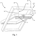
- Fig. 1 a schematic view of a window 1 provided with an operating arrangement 10 according to an embodiment of the invention is shown.
- the window 1 comprises a sash 2 and a frame 3, wherein the sash 2 pivots substantially about the centre of the frame 3 during opening thereof.
- the frame 3 has, in a manner known per se, a bottom member, a top member, and two side members, which together define a frame plane, and the sash 2 has, in a corresponding manner, a bottom member, a top member, and two side members encasing a pane (not shown) and defining a sash plane. Only the top member 2a of the sash 2 and the top member 3a of the frame 3 will be referred to in more detail.
- the window may for instance be a roof window to be built into an inclined roof surface (not shown).
- the window 1 is provided with an operating arrangement 10, for closing of the window 1.
- the operating arrangement 10 is provided with an operator housing 20 which is adapted to be connected to one of the frame 3 or sash 2 from where an operating element 30 extends and is adapted to releasably connect to the corresponding opposite sash 2 or frame 3.
- this arrangement causes the operating element 30 to extend in a direction of pivotal movement of the sash 2, during opening of the window 1, as for example shown in Fig 7 .
- the operator housing 20 is connected to a top member 3a of the frame 3, from where the operating element 30 extends and is adapted to releasably connect to a part of the top member 2a of the sash 2.
- the releasable connection between the sash 2 and frame 3 is adapted to be disconnected to manually handle the window 1 for example to a pivoted position, which is not limited to a certain degree of pivoting movement, as for example shown in Fig. 8 .
- the operating element 30 could be a cord or a wire, both of which types of material are cheap in production and easy to install. Furthermore the use of a cord or wire requires less power to control compared to for example the prior art use of chains.
- the operating element 30 is releasably connected to a holding element 31, provided on a part of the sash 2.
- This connection of the operating element 30 to the holding element 31 provides an easy installation as well as handling of the releasable connection.
- the operating element 30 is, in the embodiments shown in Figs 3 and 5 , provided with an engagement element 132, 232, which engages with the holding element 131, 231.
- the specific part of the sash to which the holding element 31 is provided is on an operating flap 4.
- Such operating flap 4 is often provided on the sash 2 in order to create a user-friendly handling of the window.
- the operating element 30 is connected to a holding element 31 provided in connection with the operating flap 4 connected to the sash 2.
- opening of the window 1 by a user gripping the operating flap 4 causes the operating element 30 to unwind from the operator housing 20 and extend in a direction following the movement of the operating flap 4.
- a closure of the window 1 and/or flap 4 itself causes the operating element 30 to wind up in the operator housing 20, creating a secure locking thereof, as illustrated in Fig 7(b) and (c) .
- Figs 1 , 7 and 8 only show an embodiment comprising an operating flap 4, in which a holding element 31 is arranged, the invention should not be limited thereto.
- the holding element could be provided directly on a part of the sash, such as a groove in the sash or for example the holding element could be a bracket fastened on the sash itself.
- This simple operating arrangement provides an improved operating arrangement which is easier to install in a window.
- the operator housing of the operating arrangement could simply be mounted on the frame by means of screws or the like, and the holding element could likewise simply be screwed into the operation flap of the sash or the sash itself.
- the releasable connection between the sash 2 and frame 3 is in a stepwise manner illustrated in Fig. 8(a) and (b) .
- a user may grip the operating flap 4 in order to open the window 1.
- the user may decouple the operating element 30 from the sash 2, as illustrated in Fig. 8(a) , whereby the operator housing 20 automatically winds up the operating element 30 as seen in Fig. 8(b) .
- the operating element 30 is not a disturbing element hanging freely, while for example cleaning the window.
- FIG. 2 shows a schematic view of an operator housing 20, where the operator housing 20 is provided with a drive unit 21 connected to a drive shaft 22, the drive shaft 22 being further arranged with a winding drum 23, where the winding drum 23 is actuated by one end of a spring 24, the opposite end of the spring being connected to a fixation point 25 such as the operator housing 20.
- the winding drum 23 is arranged to wind up the operating element 30, such that when in an active state of the drive unit 21, the drive shaft 22 rotates the winding drum 23 in a first direction winding up the operating element 30, and when in an inactive state the winding drum 23 is free-wheeled in a first and a second direction.
- the winding drum 23 may be rotated in a first and second direction without substantially resistance.
- the operating element 30 may therefore be unwound from the winding drum 23 without substantially resistance, such that it is easily handled during operation of the window.
- the operator may have feedback sensors to enable the operator to transmit the window position information i.e. whether the window is open or closed and secured.
- the winding drum 23 may furthermore be actuated by the force of the spring 24, which in the embodiment shown is a wrap spring 24 creating an automatic winding up of the operating element 30.
- This automated winding up of the operating element 30 is especially advantageous when pivoting the window substantially 180 degrees during for example cleaning of the window, since no operating element 30 in this way freely hangs down from the window frame creating an unwanted disturbing object.
- Other possible springs such as a torsion spring or a coil spring could be other possible choices of springs used as a biasing force.
- the drive unit 21 comprises an electric motor connected to the drive shaft 22, such as a reduction gear axle.
- the winding up of the operating element 31 may be electrically driven, which creates enough power for the window to automatically windup the operating element 30 and close the window, without any manually control by a user.
- the reduction gear may be provided in order to control the winding up of the operating element 30, such that the operating flap 4 and/or the window is closed in a proper manner. That is the reduction gear drives the drive shaft, such that a smooth non rapid closure of the window is achieved.
- the operator housing 20 of Fig. 2 is in more detail provided with a one-way clutch system 40, which is arranged to engage with the winding drum 23 in an active state of the drive unit, and disengage with the winding drum in an inactive state thereof.
- a one-way clutch system 40 may be arranged in several different ways, where a few non-limiting examples will be explained in the following in connection with the invention.
- connection element 141 for example a pawl, such as to provide a one-way clutch 140 in the direction of rotation of the motor 121 winding up the operating element 130.
- the connection between the drive shaft 122 and connection element 141 is provided by a cover element 142, which is arranged with a slit 143, in which a protrusion 144 on the connection element 141 engages.
- the connection element 141 is furthermore connected to an anchor plate 145 which rotates with the drive shaft 122.
- the one-way clutch 140 is configured to engage the drive shaft 122 with the winding drum 123 in the active state of the motor 121 and disengage the drive shaft 122 from the winding drum 123 in the inactive state.
- the engagement and disengagement between the winding drum 123 and the drive shaft 122 is obtained by the connection element 141 being forced, through the connection of the protrusion 144 in the slit 143, to engage with one end 148 in a groove 146 in the winding drum 123, best illustrated in Fig. 4 , whereby a coupling between the winding drum 123 and drive shaft 122 is obtained, when the drive unit 121 is in an active state.
- the winding drum 123 In an inactive state of the drive unit 121, the winding drum 123 is able to be rotated substantially without any resistance, due to the free-wheeled motion provided by the one-way clutch system 140.
- the end 148 of the connection element 141 decouples from the groove 146 in the winding drum 123, such that a free-wheeled motion is obtained.
- the rotation of the winding drum 123 influences the spring 124, which is tensioned such that it in an inactive state is able to wind up the operating element 130 automatically when this is released from the holding element 131.
- the drive unit 121 is arranged at an end opposite of the one-way clutch system 140.
- the spring 124 is in one end connected to a part of the housing 125 and in the other to the winding drum 123.
- the drive unit 221 is provided in the same end of the drive shaft 222 as the one-way clutch system 240, as shown in the operator housing 220 of Fig. 5 .
- the drive shaft 222 is connected to a part of the housing through a fixation point and in the other end the drive unit 221 is connected to the one-way clutch system 240.
- the one-way clutch system 240 of this embodiment is provided by a hub 241 which in an active state of the drive unit 221 is rotated, whereby the hub 241 engages with rollers 246 attached to the winding drum 223.
- This engagement creates a locking between the hub 241 and winding drum 223, such that the winding drum 223 is rotated in the direction of rotation of the drive unit 221, where the drive unit 221 may be comprised by an electrical motor. Furthermore when in an inactive state of the drive unit 221, a counter clock wise rotation of the winding drum 223 is able to disengage the roller 246 from the hub 241, such that a free-wheeled motion of the winding drum 223 is obtained, in a manner as explained in the previous embodiment.
- the winding drum 223 may as described in the previous embodiment also be influenced by the tensioning of the spring 224 connected through fixation point 225 to the housing, such that an automatic winding up of the operating element 230 is obtained when the operating element 230 is released from the holding element 231.
- the operating arrangement 10 may be provided with a control unit (not shown), which detects an opening of the window and further closes the window after a specified time interval. In case the window is opened and not manually closed again, the control unit thereby automatically closes the window. This is for example an advantageous if leaving a house without remembering to close the windows, which then automatically closes after a specified set time interval.
- the control unit may therefore be equipped with a timer, which is set to close the window after a given time. This time could for example in a given interval in minutes or hours, preferably 2-30 minutes.
- the time interval in which the window is set to close may be adjusted by a button provided on the operator housing. In this way the timer may be easily set by user.
- the time for closing the window may for example be indicated by the amount the window is opened, so a small opening equals that the window is to be closed soon i.e. 3 minutes, and a large opening equals the window is to be closed later i.e. 30 minutes.
- the operating arrangement could furthermore be equipped with a rain sensor.
- the rain sensor being able to detect rain drops falling on the window, causing the control unit to be activated to close the window automatically.
- the operating arrangement may be activated and close the window based on a signal from a remote or a mobile phone for example when a user leaves the building. And the operating arrangement may provide window status information so a user can verify whether the window is closed or open.
- the operating element may preferably automatically join with the holding element when the window is moved to a closed position, such that a secured automatic closing of the window is obtained.
- the operating arrangement could be battery powered.
- the operating arrangement could be equipped with a battery power sensor, which would create an alarm when the battery runs out of power and should be changed.
- roof windows often employ friction hinges that allow the user to position the window in an open position and the hinges will keep the window in that position.
- the disclosed operator is well suited for such windows.
Description
- The present invention relates to a roof window operating arrangement for closing of a roof window comprising a sash and a frame, in which an operator housing is adapted to be connected to one of the frame or sash and from where an operating element extends and is adapted to releasably connect to the corresponding opposite sash or frame, in which the operator housing is provided with a drive unit comprising an electric motor connected to a drive shaft, the drive shaft being further arranged with a winding drum, the winding drum being actuated by one end of a spring, the opposite end of the spring being connected to a fixed point, such as the operator housing, where the winding drum is arranged to wind up the operating element.
- Windows of this kind are often installed out of reach high in the ceiling of a roof, which makes them difficult to manually open or close. They are therefore often equipped with an electrically driven operating arrangement, with which an opening or closing of the roof window may be controlled by for example a remote control handled by a user. Such roof window operating arrangements are therefore often of a somewhat complex structure being equipped with for example power demanding drive units, which controls a connection element connecting the sash and frame.
- As with all windows there are demands for the windows being provided with emergency escape means, for example in the case of fire. The operating arrangements provided to control the windows are therefore often provided with releasable attachment means between the sash and frame, such that the window may be pivoted to such an extent as to create an emergency escape.
- An example of such a roof window comprising an electrically driven operating arrangement can be found in Applicant's
European patent EP 1 856 358 B1 . This document discloses an operating arrangement with an operator housing connected to a frame and an operating element extending from the frame to the sash, to which it releasably connects with a part thereof. In more detail, the operator housing is provided with an operator chain, working as the operating element and being operated by the operator housing when closing and opening the window. This kind of electrically driven operating arrangement has a fairly complex coupling between the sash and frame due to the forces exerted during operation thereof. The releasable coupling is in more detail provided by a male part attached to an end of the chain, which male part connects with a female part of the window frame. The connection between the male and female part may be released by exerting a certain amount of force to overcome a frictional and/or elastic resistance provided by the connection. - Although such existing releasable operating arrangements may be installed quite easily, their complex arrangement and secure coupling between the male and female part may however still be difficult to install properly, this due to the series of components which have to be fitted together, with regard to for example mutual position.
- Furthermore, if installed high in the ceiling of a roof the components of the releasable connection may be hard to reach and the decoupling of the sash and frame hard to manually handle. Even if provided in reach in the ceiling of a roof such electrically driven operating arrangements are often expensive to produce and require a certain power in order to be operated. Moreover, they may not be manually overruled, for example such as to be closed by hand, since they are electrically driven and thereby self locking.
- Therefore an increased demand of operating arrangements, which are in reach for manually handling of a roof window exist, such as for example a more simple operating arrangements which is cheaper in production and easier to install and operate.
- Further examples of prior art arrangements are found in
EP 2 508 704 A2DE 20 2004 008762 U1 - With this background it is the object of the present invention to provide a roof window operating arrangement according to the introduction, which operating arrangement is less demanding and complex in installation and which furthermore provides for an improved ease of handling.
- This and further objects are met by the provision of a roof window operating arrangement of the kind mentioned in the introduction and which is furthermore characterised by the features of the characterising portion of each of
independent claims - Thereby a roof window operating arrangement is provided which in an active state of the drive unit rotates the winding drum in a first direction, whereby the operating element is wound up. The force created by the drive unit in the active state is big enough to rotate the winding drum, such that the operator element not only winds up on the winding drum but also closes the roof window automatically. The inactive state of the operating arrangement provides the winding drum with a free-wheeled mechanism in a first and a second direction, such that the operating element of the operating arrangement can be controlled manually, that is for example be unwound without substantially resistance.
- This type of operating arrangement is not only influenced by the force created by the drive unit, but also actuated by the force of a spring. With this spring force an automated winding up of the operating element, when the drive unit is in an inactive state, is achieved.
- Hereby a two-part control mechanism is provided, which is influenced by the force of the drive unit or the spring, such that an operating arrangement is provided which in an active as well as in an inactive state is able to automatic wind up the operating element, while at the same time preserving low resistance when unwinding of the same. The two-part control mechanism of the operating arrangement may thereby be activated by a user handling a window of the kind mentioned in the introduction. When a user opens the window the operating element is wound out from the operator housing, i.e. the winding drum, where it extends from a sash or frame to the corresponding opposite frame or sash. During pivoting of the window, the operating element may manually be released from a part of the sash, whereby the force created in the spring, from the unwinding of the operating element, is biased such as to automatically wind up the operating element. In this way the operating element is not a disturbing factor hanging freely from the operator housing when released from a part of the sash. Furthermore the arrangement of the drive unit creates a power strong enough to wind up the operating element whereby the window is closed.
- In this way the operating arrangement can be manually handled during opening as well as closing of the window, while preserving the automation of the roof window during for example closure thereof.
- Further presently preferred embodiments and further advantageous will be apparent from the following detailed description and the dependent claims.
- The invention will be described in more detail below by means of non-limiting examples of embodiments and reference to the schematic drawings, in which
-
Fig. 1 is a schematic view of a window provided with an operating arrangement according to an embodiment of the invention, -
Fig. 2 is a schematic view of an operator housing of an operating arrangement according to an embodiment of the invention, -
Fig. 3 shows a schematic view of the interior of an operator housing according to an embodiment of the invention, -
Fig. 4 shows the one-way clutch system according to the embodiment ofFig. 3 , -
Fig. 5 shows a schematic view of the interior of the operator housing in another embodiment of the invention, -
Fig. 6 shows the one-way clutch system according to the embodiment ofFig. 5 , -
Fig. 7 shows a schematic view of handling a roof window arranged with an operating arrangement according to an embodiment of the invention, where the operating element is not released, -
Fig. 8 shows another schematic view of handling a roof window arranged with an operating arrangement according to an embodiment of the invention, where the operating element is released. - In
Fig. 1 a schematic view of awindow 1 provided with anoperating arrangement 10 according to an embodiment of the invention is shown. Thewindow 1 comprises asash 2 and aframe 3, wherein the sash 2 pivots substantially about the centre of theframe 3 during opening thereof. Theframe 3 has, in a manner known per se, a bottom member, a top member, and two side members, which together define a frame plane, and thesash 2 has, in a corresponding manner, a bottom member, a top member, and two side members encasing a pane (not shown) and defining a sash plane. Only thetop member 2a of thesash 2 and thetop member 3a of theframe 3 will be referred to in more detail. The window may for instance be a roof window to be built into an inclined roof surface (not shown). - The
window 1 is provided with anoperating arrangement 10, for closing of thewindow 1. Theoperating arrangement 10 is provided with anoperator housing 20 which is adapted to be connected to one of theframe 3 orsash 2 from where anoperating element 30 extends and is adapted to releasably connect to the correspondingopposite sash 2 orframe 3. - In general this arrangement causes the
operating element 30 to extend in a direction of pivotal movement of thesash 2, during opening of thewindow 1, as for example shown inFig 7 . - In the embodiment shown in
Fig. 1 theoperator housing 20 is connected to atop member 3a of theframe 3, from where theoperating element 30 extends and is adapted to releasably connect to a part of thetop member 2a of thesash 2. The releasable connection between thesash 2 andframe 3 is adapted to be disconnected to manually handle thewindow 1 for example to a pivoted position, which is not limited to a certain degree of pivoting movement, as for example shown inFig. 8 . - The
operating element 30 could be a cord or a wire, both of which types of material are cheap in production and easy to install. Furthermore the use of a cord or wire requires less power to control compared to for example the prior art use of chains. - In more detail shown in
Fig. 1 theoperating element 30 is releasably connected to aholding element 31, provided on a part of thesash 2. This connection of theoperating element 30 to theholding element 31 provides an easy installation as well as handling of the releasable connection. For providing a proper engagement between theoperating element 30 and theholding element 31, theoperating element 30 is, in the embodiments shown inFigs 3 and5 , provided with anengagement element holding element - In the embodiment shown in
Fig. 1 , the specific part of the sash to which theholding element 31 is provided, is on anoperating flap 4.Such operating flap 4 is often provided on thesash 2 in order to create a user-friendly handling of the window. In the embodiment shown it is seen how theoperating element 30 is connected to aholding element 31 provided in connection with theoperating flap 4 connected to thesash 2. As illustrated in more detail inFig. 7(a) opening of thewindow 1 by a user gripping theoperating flap 4, causes theoperating element 30 to unwind from theoperator housing 20 and extend in a direction following the movement of theoperating flap 4. Furthermore a closure of thewindow 1 and/orflap 4 itself causes theoperating element 30 to wind up in theoperator housing 20, creating a secure locking thereof, as illustrated inFig 7(b) and (c) . AlthoughFigs 1 ,7 and8 only show an embodiment comprising anoperating flap 4, in which aholding element 31 is arranged, the invention should not be limited thereto. The holding element could be provided directly on a part of the sash, such as a groove in the sash or for example the holding element could be a bracket fastened on the sash itself. - This simple operating arrangement provides an improved operating arrangement which is easier to install in a window. The operator housing of the operating arrangement could simply be mounted on the frame by means of screws or the like, and the holding element could likewise simply be screwed into the operation flap of the sash or the sash itself.
- The releasable connection between the
sash 2 andframe 3 is in a stepwise manner illustrated inFig. 8(a) and (b) . Here it is seen how a user may grip theoperating flap 4 in order to open thewindow 1. When pulled down to a certain height, the user may decouple theoperating element 30 from thesash 2, as illustrated inFig. 8(a) , whereby theoperator housing 20 automatically winds up the operatingelement 30 as seen inFig. 8(b) . In this way the operatingelement 30 is not a disturbing element hanging freely, while for example cleaning the window. - Bearing in mind the preceding description of the general arrangement and handling of the operating arrangement according to the invention, a more detailed description of examples of an operator housing and its function with regards to handling of the window will be described in the following.
- Referring to
Fig. 2 , which shows a schematic view of anoperator housing 20, where theoperator housing 20 is provided with adrive unit 21 connected to adrive shaft 22, thedrive shaft 22 being further arranged with a windingdrum 23, where the windingdrum 23 is actuated by one end of aspring 24, the opposite end of the spring being connected to a fixation point 25 such as theoperator housing 20. With this arrangement the windingdrum 23 is arranged to wind up the operatingelement 30, such that when in an active state of thedrive unit 21, thedrive shaft 22 rotates the windingdrum 23 in a first direction winding up the operatingelement 30, and when in an inactive state the windingdrum 23 is free-wheeled in a first and a second direction. By free-wheeled should be understood that the windingdrum 23 may be rotated in a first and second direction without substantially resistance. The operatingelement 30 may therefore be unwound from the windingdrum 23 without substantially resistance, such that it is easily handled during operation of the window. Generally the operator may have feedback sensors to enable the operator to transmit the window position information i.e. whether the window is open or closed and secured. - The winding
drum 23 may furthermore be actuated by the force of thespring 24, which in the embodiment shown is awrap spring 24 creating an automatic winding up of the operatingelement 30. This automated winding up of the operatingelement 30 is especially advantageous when pivoting the window substantially 180 degrees during for example cleaning of the window, since no operatingelement 30 in this way freely hangs down from the window frame creating an unwanted disturbing object. Other possible springs, such as a torsion spring or a coil spring could be other possible choices of springs used as a biasing force. - Preferably the
drive unit 21 comprises an electric motor connected to thedrive shaft 22, such as a reduction gear axle. With this arrangement the winding up of the operatingelement 31 may be electrically driven, which creates enough power for the window to automatically windup the operatingelement 30 and close the window, without any manually control by a user. Furthermore the reduction gear may be provided in order to control the winding up of the operatingelement 30, such that theoperating flap 4 and/or the window is closed in a proper manner. That is the reduction gear drives the drive shaft, such that a smooth non rapid closure of the window is achieved. - The
operator housing 20 ofFig. 2 is in more detail provided with a one-wayclutch system 40, which is arranged to engage with the windingdrum 23 in an active state of the drive unit, and disengage with the winding drum in an inactive state thereof. Such one-way clutch system may be arranged in several different ways, where a few non-limiting examples will be explained in the following in connection with the invention. - An embodiment of the operator housing is in more detail shown in
Fig. 3 . Here the one-wayclutch system 140 is provided by thedrive shaft 122 being connected to the windingdrum 123 by aconnection element 141, for example a pawl, such as to provide a one-way clutch 140 in the direction of rotation of themotor 121 winding up theoperating element 130. The connection between thedrive shaft 122 andconnection element 141 is provided by acover element 142, which is arranged with aslit 143, in which aprotrusion 144 on theconnection element 141 engages. Theconnection element 141 is furthermore connected to ananchor plate 145 which rotates with thedrive shaft 122. In this way the one-way clutch 140 is configured to engage thedrive shaft 122 with the windingdrum 123 in the active state of themotor 121 and disengage thedrive shaft 122 from the windingdrum 123 in the inactive state. The engagement and disengagement between the windingdrum 123 and thedrive shaft 122 is obtained by theconnection element 141 being forced, through the connection of theprotrusion 144 in theslit 143, to engage with oneend 148 in agroove 146 in the windingdrum 123, best illustrated inFig. 4 , whereby a coupling between the windingdrum 123 and driveshaft 122 is obtained, when thedrive unit 121 is in an active state. In this way a locking mechanism between the windingdrum 123 and thedrive shaft 122 is obtained, such that a rotation of thedrive unit 121 rotates thedrive shaft 122 and forces the windingdrum 123 to rotate in the direction of thedrive shaft 122 causing theoperating element 130 to wind up in theoperator housing 120. - In an inactive state of the
drive unit 121, the windingdrum 123 is able to be rotated substantially without any resistance, due to the free-wheeled motion provided by the one-wayclutch system 140. When rotating the windingdrum 123 counter clock wise, compared to the arrows ofFig. 4 , theend 148 of theconnection element 141 decouples from thegroove 146 in the windingdrum 123, such that a free-wheeled motion is obtained. - Furthermore the rotation of the winding
drum 123 influences thespring 124, which is tensioned such that it in an inactive state is able to wind up theoperating element 130 automatically when this is released from the holdingelement 131. - In the embodiment shown in
Fig. 3 , thedrive unit 121 is arranged at an end opposite of the one-wayclutch system 140. Thespring 124 is in one end connected to a part of thehousing 125 and in the other to the windingdrum 123. - In another embodiment of the invention the
drive unit 221 is provided in the same end of thedrive shaft 222 as the one-wayclutch system 240, as shown in theoperator housing 220 ofFig. 5 . Here thedrive shaft 222 is connected to a part of the housing through a fixation point and in the other end thedrive unit 221 is connected to the one-wayclutch system 240. The one-wayclutch system 240 of this embodiment is provided by ahub 241 which in an active state of thedrive unit 221 is rotated, whereby thehub 241 engages withrollers 246 attached to the windingdrum 223. This engagement creates a locking between thehub 241 and windingdrum 223, such that the windingdrum 223 is rotated in the direction of rotation of thedrive unit 221, where thedrive unit 221 may be comprised by an electrical motor. Furthermore when in an inactive state of thedrive unit 221, a counter clock wise rotation of the windingdrum 223 is able to disengage theroller 246 from thehub 241, such that a free-wheeled motion of the windingdrum 223 is obtained, in a manner as explained in the previous embodiment. - In this embodiment the winding
drum 223 may as described in the previous embodiment also be influenced by the tensioning of thespring 224 connected throughfixation point 225 to the housing, such that an automatic winding up of theoperating element 230 is obtained when theoperating element 230 is released from the holdingelement 231. - In further developments of the embodiments described, the operating
arrangement 10 may be provided with a control unit (not shown), which detects an opening of the window and further closes the window after a specified time interval. In case the window is opened and not manually closed again, the control unit thereby automatically closes the window. This is for example an advantageous if leaving a house without remembering to close the windows, which then automatically closes after a specified set time interval. The control unit may therefore be equipped with a timer, which is set to close the window after a given time. This time could for example in a given interval in minutes or hours, preferably 2-30 minutes. The time interval in which the window is set to close, may be adjusted by a button provided on the operator housing. In this way the timer may be easily set by user. The time for closing the window may for example be indicated by the amount the window is opened, so a small opening equals that the window is to be closed soon i.e. 3 minutes, and a large opening equals the window is to be closed later i.e. 30 minutes. - The operating arrangement could furthermore be equipped with a rain sensor. The rain sensor being able to detect rain drops falling on the window, causing the control unit to be activated to close the window automatically. The operating arrangement may be activated and close the window based on a signal from a remote or a mobile phone for example when a user leaves the building. And the operating arrangement may provide window status information so a user can verify whether the window is closed or open.
- With the automatic closure of the window, whether due to rain or a timer set to close after a specified time, the operating element may preferably automatically join with the holding element when the window is moved to a closed position, such that a secured automatic closing of the window is obtained.
- Instead of being electrically powered the operating arrangement could be battery powered. In this case the operating arrangement could be equipped with a battery power sensor, which would create an alarm when the battery runs out of power and should be changed.
- Generally roof windows often employ friction hinges that allow the user to position the window in an open position and the hinges will keep the window in that position. The disclosed operator is well suited for such windows.
Claims (14)
- A roof window operating arrangement (10) for closing of a roof window (1) comprising a sash (2) and a frame (3), wherein the operating arrangement comprises an operator housing (120) which is adapted to be connected to one of the frame (3) or sash (2) and from where an operating element (130) extends and is adapted to releasably connect to the corresponding opposite sash (2) or frame (3), wherein the operator housing (120) is provided with a drive unit (121) comprising an electric motor connected to a drive shaft (122) of the operating arrangement, the drive shaft (122) being further arranged with a winding drum (123), the winding drum (123) being actuated by one end of a spring (124), the opposite end of the spring being connected to a fixed point (125) such as the operator housing (120), wherein the winding drum (123) is arranged to wind up the operating element (130), characterized in that the operating arrangement comprises a one-way clutch system (140) which is arranged to engage the drive unit (121) with the winding drum (23) in an active state and disengage the drive unit (121) from the winding drum in an inactive state, wherein the one-way clutch system (140) is provided by the drive shaft (122) being connected to the winding drum (123) by a connection element (141), such as to provide a one-way clutch (140) in the direction of rotation of the motor (121) winding up the operating element (130), wherein the connection between the drive shaft (122) and the connection element (141) is provided by a cover element (142), which is arranged with a slit (143), in which a protrusion (144) on the connection element (141) engages, wherein the connection element (141) is furthermore connected to an anchor plate (145) which rotates with the drive shaft (122), and that the one-way clutch (140) is configured to engage the drive shaft (122) with the winding drum (123) in the active state of the drive unit (121) and disengage the drive shaft (122) from the winding drum (123) in the inactive state of the drive unit (121), wherein the engagement and disengagement between the winding drum (123) and the drive shaft (122) is obtained by the connection element (141) being forced, through the connection of the protrusion (144) in the slit (143), to engage with one end (148) in a groove (146) in the winding drum (123), and that when in the active state of the drive unit (121), the drive shaft (122) rotates the winding drum (123) in a first direction winding up the operating element (130), and when in the inactive state the winding drum (123) is free-wheeled in a first and a second direction, and that the winding drum (123) is furthermore influenced by the force of the spring (124) creating an automatic winding up of the operating element (130) when the drive unit is in an inactive state.
- A roof window operating arrangement (10) for closing of a roof window (1) comprising a sash (2) and a frame (3), wherein the operating arrangement comprises an operator housing (220) which is adapted to be connected to one of the frame (3) or sash (2) and from where an operating element (230) extends and is adapted to releasably connect to the corresponding opposite sash (2) or frame (3), wherein the operator housing (220) is provided with a drive unit (221) comprising an electric motor connected to a drive shaft (222) of the operating arrangement, the drive shaft (222) being further arranged with a winding drum (223), the winding drum (223) being actuated by one end of a spring (224), the opposite end of the spring being connected to a fixed point (225) such as the operator housing (220), wherein the winding drum (223) is arranged to wind up the operating element (230), characterized in that the operating arrangement comprises a one-way clutch system (240) which is arranged to engage the drive unit (221) with the winding drum (223) in an active state, and disengage the drive unit (221) from the winding drum in an inactive state, and that the drive unit (221) is provided in the same end of the drive shaft (222) as the one-way clutch system (240), the drive shaft (222) being connected to a part of the housing through a fixation point and in the other end the drive unit (221) is connected to the one-way clutch system (240), and that the one-way clutch system (240) is provided by a hub (241) which in an active state of the drive unit (221) is rotated, whereby the hub (241) engages with rollers (246) attached to the winding drum (223), creating a locking between the hub (241) and the winding drum (223), such that the winding drum (223) is rotated in the direction of rotation of the drive unit (221), and that when in an inactive state of the drive unit (221), a counter clock wise rotation of the winding drum (223) is able to disengage the roller (246) from the hub (241), such that a free-wheeled motion of the winding drum (223) is obtained, and that when in the active state of the drive unit (221), the drive shaft (222) rotates the winding drum (223) in a first direction winding up the operating element (230), and when in the inactive state the winding drum (223) is free-wheeled in a first and a second direction, and that the winding drum (223) is furthermore influenced by the force of the spring (224) creating an automatic winding up of the operating element (230) when the drive unit is in an inactive state.
- A roof window comprising a roof window operating arrangement (10) according to claim 1 or 2, wherein the operator housing (120; 220) is connected to the frame (3) and the operating element (130; 230) is releasably connected to the sash (2) or vice versa.
- A roof window according to claim 3, wherein the operating element (130; 230) is releasably connected to a holding element (131; 231) such as a bracket, provided on a part of the sash (2).
- A roof window according to claim 4, wherein the holding element (131; 231) is provided in connection with an operating flap (4) connected to the sash (2).
- A roof window according to any of claims 4 to 5, wherein the operating element (130; 230) is adapted to automatically join with the holding element (131; 231) when the window is moved to a closed position.
- A roof window according to any one of claims 3 to 6, wherein the operating element (130; 230) is a cord or a wire.
- A roof window according to any one of claims 3 to 7, when dependent on claim 1, wherein the drive unit (121; 221) comprises an electric motor connected to the drive shaft (122; 222), such as a reduction gear axle.
- A roof window according to any one of claims 3 to 8, wherein the operating arrangement (10) is provided with a control unit, which detects an opening of the window and closes the window after a specified time interval.
- A roof window according to any one of claims 3 to 9, wherein the operating arrangement (10) is provided with a rain sensor.
- A roof window according to any one of claims 3 to 10, wherein the operating arrangement (10) is electrically powered.
- A roof window according to any one of claims 3 to 11, wherein the operating arrangement (10) is battery powered.
- A roof window according to any one of claims 3 to 12 comprising a pivoting sash (2) and a frame (3), wherein the sash (2) pivots substantially about the centre of the frame (3).
- A roof window according to any one of claims 3 to 13 wherein the operating arrangement (10) is configured to automatically close the window (1) without preventing manual opening and closing of the window (1).
Priority Applications (1)
| Application Number | Priority Date | Filing Date | Title |
|---|---|---|---|
| EP14166314.6A EP2957700B1 (en) | 2014-04-29 | 2014-04-29 | Roof window operator |
Applications Claiming Priority (1)
| Application Number | Priority Date | Filing Date | Title |
|---|---|---|---|
| EP14166314.6A EP2957700B1 (en) | 2014-04-29 | 2014-04-29 | Roof window operator |
Publications (2)
| Publication Number | Publication Date |
|---|---|
| EP2957700A1 EP2957700A1 (en) | 2015-12-23 |
| EP2957700B1 true EP2957700B1 (en) | 2021-08-11 |
Family
ID=50588570
Family Applications (1)
| Application Number | Title | Priority Date | Filing Date |
|---|---|---|---|
| EP14166314.6A Active EP2957700B1 (en) | 2014-04-29 | 2014-04-29 | Roof window operator |
Country Status (1)
| Country | Link |
|---|---|
| EP (1) | EP2957700B1 (en) |
Families Citing this family (9)
| Publication number | Priority date | Publication date | Assignee | Title |
|---|---|---|---|---|
| CN106677660B (en) * | 2016-12-30 | 2018-03-23 | 深圳春沐源控股有限公司 | Rotating window, method and device for controlling window rotation |
| CN108678589B (en) * | 2017-06-21 | 2020-02-14 | 江苏易明昌建设工程有限公司 | Hinge mechanism and window with same |
| CN107060568B (en) * | 2017-06-21 | 2018-02-16 | 广东皇派家居科技有限公司 | The window that a kind of rainy day automatic slowly based on water freezing triggering is closed |
| EP3505696B1 (en) | 2018-01-02 | 2024-03-27 | VKR Holding A/S | Automated window for installation in an inclined roof |
| CN109505480A (en) * | 2018-12-29 | 2019-03-22 | 苏州市富尔达科技股份有限公司 | A kind of automatic warming shutting window device |
| CN109538058A (en) * | 2018-12-29 | 2019-03-29 | 苏州市富尔达科技股份有限公司 | A kind of warming fire prevention shutting window device |
| KR102076822B1 (en) * | 2019-06-11 | 2020-02-12 | 서종용 | Automatic window opening and closing device |
| EP3770355B1 (en) * | 2019-07-24 | 2022-06-29 | VKR Holding A/S | A roof window arrangement comprising a manual operating assembly with an integrated control part |
| EP3770356B1 (en) * | 2019-07-24 | 2022-06-29 | VKR Holding A/S | An upgrade kit for roof window comprising a manual operating assembly, and a roof window arrangement comprising such an upgrade kit |
Family Cites Families (3)
| Publication number | Priority date | Publication date | Assignee | Title |
|---|---|---|---|---|
| DE202004008762U1 (en) * | 2003-10-15 | 2004-09-30 | Merkle, Hans | Automatic roof light closer connects pull rope to spring as engaged or released off signal-responsive geared electromotor submitting to rain sensor. |
| PL1856358T3 (en) | 2005-02-28 | 2009-12-31 | Vkr Holding As | Releasable coupling |
| DE102011001156A1 (en) * | 2011-03-09 | 2012-09-13 | Hans Arnhold | window closer |
-
2014
- 2014-04-29 EP EP14166314.6A patent/EP2957700B1/en active Active
Non-Patent Citations (1)
| Title |
|---|
| None * |
Also Published As
| Publication number | Publication date |
|---|---|
| EP2957700A1 (en) | 2015-12-23 |
Similar Documents
| Publication | Publication Date | Title |
|---|---|---|
| EP2957700B1 (en) | Roof window operator | |
| US10975619B2 (en) | Methods and apparatus to control architectural opening covering assemblies | |
| EP2719854B1 (en) | Methods and apparatus to control an architectural opening covering assembly | |
| AU2011326816B2 (en) | Modular anti-reversible power spring apparatus and method | |
| KR100706328B1 (en) | Apparatus for openning and closing of a slide door | |
| EP2924209B1 (en) | An openable roof window with active lock | |
| KR101390363B1 (en) | Sliding door apparatus | |
| JP7040751B2 (en) | Switchgear | |
| JP2010007408A (en) | Door having tension spring counter weight, and its actuator | |
| US20210396063A1 (en) | Shaft mounted overhead door operator, clutch and kit therefor | |
| JP4829607B2 (en) | Automatic opening and closing device of bay window | |
| JPH0330559Y2 (en) |
Legal Events
| Date | Code | Title | Description |
|---|---|---|---|
| PUAI | Public reference made under article 153(3) epc to a published international application that has entered the european phase |
Free format text: ORIGINAL CODE: 0009012 |
|
| AK | Designated contracting states |
Kind code of ref document: A1 Designated state(s): AL AT BE BG CH CY CZ DE DK EE ES FI FR GB GR HR HU IE IS IT LI LT LU LV MC MK MT NL NO PL PT RO RS SE SI SK SM TR |
|
| AX | Request for extension of the european patent |
Extension state: BA ME |
|
| 17P | Request for examination filed |
Effective date: 20151229 |
|
| RBV | Designated contracting states (corrected) |
Designated state(s): AL AT BE BG CH CY CZ DE DK EE ES FI FR GB GR HR HU IE IS IT LI LT LU LV MC MK MT NL NO PL PT RO RS SE SI SK SM TR |
|
| STAA | Information on the status of an ep patent application or granted ep patent |
Free format text: STATUS: EXAMINATION IS IN PROGRESS |
|
| 17Q | First examination report despatched |
Effective date: 20190201 |
|
| STAA | Information on the status of an ep patent application or granted ep patent |
Free format text: STATUS: EXAMINATION IS IN PROGRESS |
|
| GRAP | Despatch of communication of intention to grant a patent |
Free format text: ORIGINAL CODE: EPIDOSNIGR1 |
|
| STAA | Information on the status of an ep patent application or granted ep patent |
Free format text: STATUS: GRANT OF PATENT IS INTENDED |
|
| INTG | Intention to grant announced |
Effective date: 20210316 |
|
| GRAS | Grant fee paid |
Free format text: ORIGINAL CODE: EPIDOSNIGR3 |
|
| GRAA | (expected) grant |
Free format text: ORIGINAL CODE: 0009210 |
|
| STAA | Information on the status of an ep patent application or granted ep patent |
Free format text: STATUS: THE PATENT HAS BEEN GRANTED |
|
| AK | Designated contracting states |
Kind code of ref document: B1 Designated state(s): AL AT BE BG CH CY CZ DE DK EE ES FI FR GB GR HR HU IE IS IT LI LT LU LV MC MK MT NL NO PL PT RO RS SE SI SK SM TR |
|
| REG | Reference to a national code |
Ref country code: GB Ref legal event code: FG4D |
|
| REG | Reference to a national code |
Ref country code: CH Ref legal event code: EP |
|
| REG | Reference to a national code |
Ref country code: DE Ref legal event code: R096 Ref document number: 602014079327 Country of ref document: DE |
|
| REG | Reference to a national code |
Ref country code: IE Ref legal event code: FG4D Ref country code: AT Ref legal event code: REF Ref document number: 1419562 Country of ref document: AT Kind code of ref document: T Effective date: 20210915 |
|
| REG | Reference to a national code |
Ref country code: LT Ref legal event code: MG9D |
|
| REG | Reference to a national code |
Ref country code: NL Ref legal event code: MP Effective date: 20210811 |
|
| REG | Reference to a national code |
Ref country code: AT Ref legal event code: MK05 Ref document number: 1419562 Country of ref document: AT Kind code of ref document: T Effective date: 20210811 |
|
| PG25 | Lapsed in a contracting state [announced via postgrant information from national office to epo] |
Ref country code: RS Free format text: LAPSE BECAUSE OF FAILURE TO SUBMIT A TRANSLATION OF THE DESCRIPTION OR TO PAY THE FEE WITHIN THE PRESCRIBED TIME-LIMIT Effective date: 20210811 Ref country code: SE Free format text: LAPSE BECAUSE OF FAILURE TO SUBMIT A TRANSLATION OF THE DESCRIPTION OR TO PAY THE FEE WITHIN THE PRESCRIBED TIME-LIMIT Effective date: 20210811 Ref country code: HR Free format text: LAPSE BECAUSE OF FAILURE TO SUBMIT A TRANSLATION OF THE DESCRIPTION OR TO PAY THE FEE WITHIN THE PRESCRIBED TIME-LIMIT Effective date: 20210811 Ref country code: LT Free format text: LAPSE BECAUSE OF FAILURE TO SUBMIT A TRANSLATION OF THE DESCRIPTION OR TO PAY THE FEE WITHIN THE PRESCRIBED TIME-LIMIT Effective date: 20210811 Ref country code: AT Free format text: LAPSE BECAUSE OF FAILURE TO SUBMIT A TRANSLATION OF THE DESCRIPTION OR TO PAY THE FEE WITHIN THE PRESCRIBED TIME-LIMIT Effective date: 20210811 Ref country code: BG Free format text: LAPSE BECAUSE OF FAILURE TO SUBMIT A TRANSLATION OF THE DESCRIPTION OR TO PAY THE FEE WITHIN THE PRESCRIBED TIME-LIMIT Effective date: 20211111 Ref country code: PT Free format text: LAPSE BECAUSE OF FAILURE TO SUBMIT A TRANSLATION OF THE DESCRIPTION OR TO PAY THE FEE WITHIN THE PRESCRIBED TIME-LIMIT Effective date: 20211213 Ref country code: NO Free format text: LAPSE BECAUSE OF FAILURE TO SUBMIT A TRANSLATION OF THE DESCRIPTION OR TO PAY THE FEE WITHIN THE PRESCRIBED TIME-LIMIT Effective date: 20211111 Ref country code: ES Free format text: LAPSE BECAUSE OF FAILURE TO SUBMIT A TRANSLATION OF THE DESCRIPTION OR TO PAY THE FEE WITHIN THE PRESCRIBED TIME-LIMIT Effective date: 20210811 Ref country code: FI Free format text: LAPSE BECAUSE OF FAILURE TO SUBMIT A TRANSLATION OF THE DESCRIPTION OR TO PAY THE FEE WITHIN THE PRESCRIBED TIME-LIMIT Effective date: 20210811 |
|
| PG25 | Lapsed in a contracting state [announced via postgrant information from national office to epo] |
Ref country code: PL Free format text: LAPSE BECAUSE OF FAILURE TO SUBMIT A TRANSLATION OF THE DESCRIPTION OR TO PAY THE FEE WITHIN THE PRESCRIBED TIME-LIMIT Effective date: 20210811 Ref country code: LV Free format text: LAPSE BECAUSE OF FAILURE TO SUBMIT A TRANSLATION OF THE DESCRIPTION OR TO PAY THE FEE WITHIN THE PRESCRIBED TIME-LIMIT Effective date: 20210811 Ref country code: GR Free format text: LAPSE BECAUSE OF FAILURE TO SUBMIT A TRANSLATION OF THE DESCRIPTION OR TO PAY THE FEE WITHIN THE PRESCRIBED TIME-LIMIT Effective date: 20211112 |
|
| PG25 | Lapsed in a contracting state [announced via postgrant information from national office to epo] |
Ref country code: NL Free format text: LAPSE BECAUSE OF FAILURE TO SUBMIT A TRANSLATION OF THE DESCRIPTION OR TO PAY THE FEE WITHIN THE PRESCRIBED TIME-LIMIT Effective date: 20210811 |
|
| PG25 | Lapsed in a contracting state [announced via postgrant information from national office to epo] |
Ref country code: DK Free format text: LAPSE BECAUSE OF FAILURE TO SUBMIT A TRANSLATION OF THE DESCRIPTION OR TO PAY THE FEE WITHIN THE PRESCRIBED TIME-LIMIT Effective date: 20210811 |
|
| REG | Reference to a national code |
Ref country code: DE Ref legal event code: R097 Ref document number: 602014079327 Country of ref document: DE |
|
| PG25 | Lapsed in a contracting state [announced via postgrant information from national office to epo] |
Ref country code: SM Free format text: LAPSE BECAUSE OF FAILURE TO SUBMIT A TRANSLATION OF THE DESCRIPTION OR TO PAY THE FEE WITHIN THE PRESCRIBED TIME-LIMIT Effective date: 20210811 Ref country code: SK Free format text: LAPSE BECAUSE OF FAILURE TO SUBMIT A TRANSLATION OF THE DESCRIPTION OR TO PAY THE FEE WITHIN THE PRESCRIBED TIME-LIMIT Effective date: 20210811 Ref country code: RO Free format text: LAPSE BECAUSE OF FAILURE TO SUBMIT A TRANSLATION OF THE DESCRIPTION OR TO PAY THE FEE WITHIN THE PRESCRIBED TIME-LIMIT Effective date: 20210811 Ref country code: EE Free format text: LAPSE BECAUSE OF FAILURE TO SUBMIT A TRANSLATION OF THE DESCRIPTION OR TO PAY THE FEE WITHIN THE PRESCRIBED TIME-LIMIT Effective date: 20210811 Ref country code: CZ Free format text: LAPSE BECAUSE OF FAILURE TO SUBMIT A TRANSLATION OF THE DESCRIPTION OR TO PAY THE FEE WITHIN THE PRESCRIBED TIME-LIMIT Effective date: 20210811 Ref country code: AL Free format text: LAPSE BECAUSE OF FAILURE TO SUBMIT A TRANSLATION OF THE DESCRIPTION OR TO PAY THE FEE WITHIN THE PRESCRIBED TIME-LIMIT Effective date: 20210811 |
|
| PLBE | No opposition filed within time limit |
Free format text: ORIGINAL CODE: 0009261 |
|
| STAA | Information on the status of an ep patent application or granted ep patent |
Free format text: STATUS: NO OPPOSITION FILED WITHIN TIME LIMIT |
|
| 26N | No opposition filed |
Effective date: 20220512 |
|
| PG25 | Lapsed in a contracting state [announced via postgrant information from national office to epo] |
Ref country code: IT Free format text: LAPSE BECAUSE OF FAILURE TO SUBMIT A TRANSLATION OF THE DESCRIPTION OR TO PAY THE FEE WITHIN THE PRESCRIBED TIME-LIMIT Effective date: 20210811 |
|
| PG25 | Lapsed in a contracting state [announced via postgrant information from national office to epo] |
Ref country code: SI Free format text: LAPSE BECAUSE OF FAILURE TO SUBMIT A TRANSLATION OF THE DESCRIPTION OR TO PAY THE FEE WITHIN THE PRESCRIBED TIME-LIMIT Effective date: 20210811 |
|
| REG | Reference to a national code |
Ref country code: CH Ref legal event code: PL |
|
| GBPC | Gb: european patent ceased through non-payment of renewal fee |
Effective date: 20220429 |
|
| REG | Reference to a national code |
Ref country code: BE Ref legal event code: MM Effective date: 20220430 |
|
| PG25 | Lapsed in a contracting state [announced via postgrant information from national office to epo] |
Ref country code: MC Free format text: LAPSE BECAUSE OF FAILURE TO SUBMIT A TRANSLATION OF THE DESCRIPTION OR TO PAY THE FEE WITHIN THE PRESCRIBED TIME-LIMIT Effective date: 20210811 Ref country code: LU Free format text: LAPSE BECAUSE OF NON-PAYMENT OF DUE FEES Effective date: 20220429 Ref country code: LI Free format text: LAPSE BECAUSE OF NON-PAYMENT OF DUE FEES Effective date: 20220430 Ref country code: GB Free format text: LAPSE BECAUSE OF NON-PAYMENT OF DUE FEES Effective date: 20220429 Ref country code: CH Free format text: LAPSE BECAUSE OF NON-PAYMENT OF DUE FEES Effective date: 20220430 |
|
| PG25 | Lapsed in a contracting state [announced via postgrant information from national office to epo] |
Ref country code: BE Free format text: LAPSE BECAUSE OF NON-PAYMENT OF DUE FEES Effective date: 20220430 |
|
| PG25 | Lapsed in a contracting state [announced via postgrant information from national office to epo] |
Ref country code: IE Free format text: LAPSE BECAUSE OF NON-PAYMENT OF DUE FEES Effective date: 20220429 |
|
| PGFP | Annual fee paid to national office [announced via postgrant information from national office to epo] |
Ref country code: FR Payment date: 20230328 Year of fee payment: 10 |
|
| PGFP | Annual fee paid to national office [announced via postgrant information from national office to epo] |
Ref country code: DE Payment date: 20230307 Year of fee payment: 10 |
|
| PG25 | Lapsed in a contracting state [announced via postgrant information from national office to epo] |
Ref country code: HU Free format text: LAPSE BECAUSE OF FAILURE TO SUBMIT A TRANSLATION OF THE DESCRIPTION OR TO PAY THE FEE WITHIN THE PRESCRIBED TIME-LIMIT; INVALID AB INITIO Effective date: 20140429 |