EP2957513A1 - Label peeling device, fluid ejection device, and label peeling method - Google Patents
Label peeling device, fluid ejection device, and label peeling method Download PDFInfo
- Publication number
- EP2957513A1 EP2957513A1 EP15172695.7A EP15172695A EP2957513A1 EP 2957513 A1 EP2957513 A1 EP 2957513A1 EP 15172695 A EP15172695 A EP 15172695A EP 2957513 A1 EP2957513 A1 EP 2957513A1
- Authority
- EP
- European Patent Office
- Prior art keywords
- peeling
- label
- label paper
- unit
- labels
- Prior art date
- Legal status (The legal status is an assumption and is not a legal conclusion. Google has not performed a legal analysis and makes no representation as to the accuracy of the status listed.)
- Granted
Links
- 239000012530 fluid Substances 0.000 title claims description 30
- 238000000034 method Methods 0.000 title claims description 9
- 238000012546 transfer Methods 0.000 claims description 5
- 230000007246 mechanism Effects 0.000 claims description 2
- 206010040844 Skin exfoliation Diseases 0.000 description 402
- NJPPVKZQTLUDBO-UHFFFAOYSA-N novaluron Chemical compound C1=C(Cl)C(OC(F)(F)C(OC(F)(F)F)F)=CC=C1NC(=O)NC(=O)C1=C(F)C=CC=C1F NJPPVKZQTLUDBO-UHFFFAOYSA-N 0.000 description 8
- 238000001514 detection method Methods 0.000 description 5
- 239000000523 sample Substances 0.000 description 4
- 238000011144 upstream manufacturing Methods 0.000 description 4
- 238000004891 communication Methods 0.000 description 3
- 230000006870 function Effects 0.000 description 3
- 239000011435 rock Substances 0.000 description 3
- 230000008859 change Effects 0.000 description 2
- 239000003086 colorant Substances 0.000 description 2
- 230000007423 decrease Effects 0.000 description 2
- 230000008569 process Effects 0.000 description 2
- 230000009471 action Effects 0.000 description 1
- 230000001154 acute effect Effects 0.000 description 1
- 238000005452 bending Methods 0.000 description 1
- 230000005540 biological transmission Effects 0.000 description 1
- 239000011248 coating agent Substances 0.000 description 1
- 238000010586 diagram Methods 0.000 description 1
- 239000000463 material Substances 0.000 description 1
- 238000012986 modification Methods 0.000 description 1
- 230000004048 modification Effects 0.000 description 1
- 238000012545 processing Methods 0.000 description 1
- 238000001454 recorded image Methods 0.000 description 1
- 238000000926 separation method Methods 0.000 description 1
Images







Classifications
-
- B—PERFORMING OPERATIONS; TRANSPORTING
- B32—LAYERED PRODUCTS
- B32B—LAYERED PRODUCTS, i.e. PRODUCTS BUILT-UP OF STRATA OF FLAT OR NON-FLAT, e.g. CELLULAR OR HONEYCOMB, FORM
- B32B43/00—Operations specially adapted for layered products and not otherwise provided for, e.g. repairing; Apparatus therefor
- B32B43/006—Delaminating
-
- B—PERFORMING OPERATIONS; TRANSPORTING
- B41—PRINTING; LINING MACHINES; TYPEWRITERS; STAMPS
- B41J—TYPEWRITERS; SELECTIVE PRINTING MECHANISMS, i.e. MECHANISMS PRINTING OTHERWISE THAN FROM A FORME; CORRECTION OF TYPOGRAPHICAL ERRORS
- B41J3/00—Typewriters or selective printing or marking mechanisms characterised by the purpose for which they are constructed
- B41J3/407—Typewriters or selective printing or marking mechanisms characterised by the purpose for which they are constructed for marking on special material
- B41J3/4075—Tape printers; Label printers
-
- B—PERFORMING OPERATIONS; TRANSPORTING
- B65—CONVEYING; PACKING; STORING; HANDLING THIN OR FILAMENTARY MATERIAL
- B65C—LABELLING OR TAGGING MACHINES, APPARATUS, OR PROCESSES
- B65C9/00—Details of labelling machines or apparatus
- B65C9/0006—Removing backing sheets
-
- B—PERFORMING OPERATIONS; TRANSPORTING
- B32—LAYERED PRODUCTS
- B32B—LAYERED PRODUCTS, i.e. PRODUCTS BUILT-UP OF STRATA OF FLAT OR NON-FLAT, e.g. CELLULAR OR HONEYCOMB, FORM
- B32B38/00—Ancillary operations in connection with laminating processes
- B32B38/10—Removing layers, or parts of layers, mechanically or chemically
-
- B—PERFORMING OPERATIONS; TRANSPORTING
- B65—CONVEYING; PACKING; STORING; HANDLING THIN OR FILAMENTARY MATERIAL
- B65C—LABELLING OR TAGGING MACHINES, APPARATUS, OR PROCESSES
- B65C9/00—Details of labelling machines or apparatus
- B65C9/0006—Removing backing sheets
- B65C2009/0009—Removing backing sheets by means of a peeling tip
-
- Y—GENERAL TAGGING OF NEW TECHNOLOGICAL DEVELOPMENTS; GENERAL TAGGING OF CROSS-SECTIONAL TECHNOLOGIES SPANNING OVER SEVERAL SECTIONS OF THE IPC; TECHNICAL SUBJECTS COVERED BY FORMER USPC CROSS-REFERENCE ART COLLECTIONS [XRACs] AND DIGESTS
- Y10—TECHNICAL SUBJECTS COVERED BY FORMER USPC
- Y10T—TECHNICAL SUBJECTS COVERED BY FORMER US CLASSIFICATION
- Y10T156/00—Adhesive bonding and miscellaneous chemical manufacture
- Y10T156/11—Methods of delaminating, per se; i.e., separating at bonding face
- Y10T156/1105—Delaminating process responsive to feed or shape at delamination
-
- Y—GENERAL TAGGING OF NEW TECHNOLOGICAL DEVELOPMENTS; GENERAL TAGGING OF CROSS-SECTIONAL TECHNOLOGIES SPANNING OVER SEVERAL SECTIONS OF THE IPC; TECHNICAL SUBJECTS COVERED BY FORMER USPC CROSS-REFERENCE ART COLLECTIONS [XRACs] AND DIGESTS
- Y10—TECHNICAL SUBJECTS COVERED BY FORMER USPC
- Y10T—TECHNICAL SUBJECTS COVERED BY FORMER US CLASSIFICATION
- Y10T156/00—Adhesive bonding and miscellaneous chemical manufacture
- Y10T156/11—Methods of delaminating, per se; i.e., separating at bonding face
- Y10T156/1168—Gripping and pulling work apart during delaminating
- Y10T156/1174—Using roller for delamination [e.g., roller pairs operating at differing speeds or directions, etc.]
-
- Y—GENERAL TAGGING OF NEW TECHNOLOGICAL DEVELOPMENTS; GENERAL TAGGING OF CROSS-SECTIONAL TECHNOLOGIES SPANNING OVER SEVERAL SECTIONS OF THE IPC; TECHNICAL SUBJECTS COVERED BY FORMER USPC CROSS-REFERENCE ART COLLECTIONS [XRACs] AND DIGESTS
- Y10—TECHNICAL SUBJECTS COVERED BY FORMER USPC
- Y10T—TECHNICAL SUBJECTS COVERED BY FORMER US CLASSIFICATION
- Y10T156/00—Adhesive bonding and miscellaneous chemical manufacture
- Y10T156/11—Methods of delaminating, per se; i.e., separating at bonding face
- Y10T156/1168—Gripping and pulling work apart during delaminating
- Y10T156/1195—Delaminating from release surface
-
- Y—GENERAL TAGGING OF NEW TECHNOLOGICAL DEVELOPMENTS; GENERAL TAGGING OF CROSS-SECTIONAL TECHNOLOGIES SPANNING OVER SEVERAL SECTIONS OF THE IPC; TECHNICAL SUBJECTS COVERED BY FORMER USPC CROSS-REFERENCE ART COLLECTIONS [XRACs] AND DIGESTS
- Y10—TECHNICAL SUBJECTS COVERED BY FORMER USPC
- Y10T—TECHNICAL SUBJECTS COVERED BY FORMER US CLASSIFICATION
- Y10T156/00—Adhesive bonding and miscellaneous chemical manufacture
- Y10T156/17—Surface bonding means and/or assemblymeans with work feeding or handling means
- Y10T156/1788—Work traversing type and/or means applying work to wall or static structure
- Y10T156/179—Work traversing type and/or means applying work to wall or static structure with liquid applying means
-
- Y—GENERAL TAGGING OF NEW TECHNOLOGICAL DEVELOPMENTS; GENERAL TAGGING OF CROSS-SECTIONAL TECHNOLOGIES SPANNING OVER SEVERAL SECTIONS OF THE IPC; TECHNICAL SUBJECTS COVERED BY FORMER USPC CROSS-REFERENCE ART COLLECTIONS [XRACs] AND DIGESTS
- Y10—TECHNICAL SUBJECTS COVERED BY FORMER USPC
- Y10T—TECHNICAL SUBJECTS COVERED BY FORMER US CLASSIFICATION
- Y10T156/00—Adhesive bonding and miscellaneous chemical manufacture
- Y10T156/19—Delaminating means
- Y10T156/1906—Delaminating means responsive to feed or shape at delamination
-
- Y—GENERAL TAGGING OF NEW TECHNOLOGICAL DEVELOPMENTS; GENERAL TAGGING OF CROSS-SECTIONAL TECHNOLOGIES SPANNING OVER SEVERAL SECTIONS OF THE IPC; TECHNICAL SUBJECTS COVERED BY FORMER USPC CROSS-REFERENCE ART COLLECTIONS [XRACs] AND DIGESTS
- Y10—TECHNICAL SUBJECTS COVERED BY FORMER USPC
- Y10T—TECHNICAL SUBJECTS COVERED BY FORMER US CLASSIFICATION
- Y10T156/00—Adhesive bonding and miscellaneous chemical manufacture
- Y10T156/19—Delaminating means
- Y10T156/195—Delaminating roller means
- Y10T156/1956—Roller pair delaminating means
-
- Y—GENERAL TAGGING OF NEW TECHNOLOGICAL DEVELOPMENTS; GENERAL TAGGING OF CROSS-SECTIONAL TECHNOLOGIES SPANNING OVER SEVERAL SECTIONS OF THE IPC; TECHNICAL SUBJECTS COVERED BY FORMER USPC CROSS-REFERENCE ART COLLECTIONS [XRACs] AND DIGESTS
- Y10—TECHNICAL SUBJECTS COVERED BY FORMER USPC
- Y10T—TECHNICAL SUBJECTS COVERED BY FORMER US CLASSIFICATION
- Y10T156/00—Adhesive bonding and miscellaneous chemical manufacture
- Y10T156/19—Delaminating means
- Y10T156/1994—Means for delaminating from release surface
Definitions
- the present disclosure relates to a label peeling device that separates the labels from the liner backing of label paper.
- Label peeling devices that have a take-up roller for rewinding label paper conveyed from a label printer, a motor that drives the take-up roller, a peeling plate disposed between the label printer and the take-up roller to peel labels from the liner backing by bending the liner, an air cylinder that moves the peeling plate forward and back in the conveyance direction of the label paper, and a suction pad that holds the printing surface of the label, are known from the literature. When the printing surface of a label is held by the suction pad, this label peeling device separates the label from the liner by the air cylinder moving the peeling plate toward the label printer while rewinding the liner onto the take-up roller. See, for example, JP-A-2009-012851 .
- the peeling member When the peeling member is moved by an air cylinder while rewinding the label paper by driving a motor as in the label peeling device described in JP-A-2009-012851 , the peeling member may move quickly irrespective of how fast the label paper is being rewound. Because the peeling member separates from the label paper when this happens, the liner is not folded back by the peeling plate and the label cannot be peeled from the liner.
- the present invention provides a label peeling device, a fluid ejection device, and a peeling method, having the features of the respective independent claims.
- a label peeling device has a peeling unit that peels labels from label paper fed from a fluid ejection device that ejects fluid onto the label paper, the label paper including labels and a liner to which the labels are affixed.
- the peeling unit includes: a peeling member is configured to move bi-directionally between a start peeling position and an end peeling position, and fold back the liner portion of the label paper; and a conveyance unit that is disposed to the conveyance path of the label paper downstream from the peeling member and conveys the label paper.
- the peeling member is configured to move between the start peeling position and the end peeling position.
- a fluid ejection device includes: a fluid ejection unit that ejects fluid onto label paper, the label paper including labels and a liner to which the labels are affixed; and a peeling unit that is disposed to the label paper conveyance path and peels labels from label paper.
- the peeling unit includes a peeling member that is configured to move between a start peeling position and an end peeling position, and fold back the liner; and a conveyance unit that is disposed to the label paper conveyance path downstream from the peeling member and conveys the label paper.
- the peeling member is configured to move between the start peeling position and the end peeling position.
- the fluid ejection device may include the label peeling device described above.
- Some embodiments relate to a peeling method of a label peeling device having a peeling member that peels labels from label paper fed from a fluid ejection device that ejects fluid onto the label paper, the label paper including labels and a liner to which the labels are affixed, and a conveyance unit that is disposed downstream from the peeling member and conveys the label paper.
- the peeling method includes moving the peeling member from the start peeling position to the end peeling position to peel the labels from the liner.
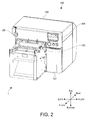
- a label peeling device 1 may be used installed to the front of the label printer 100, or more particularly to the paper exit side of the label printer 100.
- the label printer 100 is therefore described first below.
- the label printer 100 Based on image data e.g. received from a communicatively connected computer (not shown in the figure), the label printer 100 records images on the label paper P using an inkjet printhead. Note that the label printer 100 can also be used without the label peeling device 1 installed. The label peeling device 1 may therefore be installed to the label printer 100 as an optional device.
- the label paper P has a continuous liner (such as a web liner, for example) Pa, and multiple labels Pb affixed to the liner Pa with a substantially equal gap between adjacent labels Pb.
- the liner Pa and labels Pb are not limited to any particular type of material.
- the label paper P in this embodiment is provided as roll paper R, but is not so limited and may be fanfold paper, for example.
- the label printer 100 has a basically rectangular box-like case 101.
- a roll paper cover 102, discharge table 103, release lever 104, power switch 105, operating panel 106, and ink cartridge cover 107 may be disposed to the front of the case 101 where the paper exit is located.
- a roll paper supply unit 108, paper feed roller 109, platen 111, and recording head 112 may be disposed inside the case 101.
- the recording head 112 in this example is an example of a fluid ejection unit.
- the roll paper cover 102 is normally locked in a position covering the front of the roll paper supply unit 108.
- the user may work the release lever 104 to unlock the roll paper cover 102.
- the user may rotate the roll paper cover 102 together with the discharge table 103 and release lever 104 forward pivoting at the bottom of the roll paper cover 102, and thereby open the roll paper supply unit 108.
- the discharge table 103 functions as a support for receiving the discharged label paper P. If the label peeling device 1 is installed, the discharged label paper P is not received by the discharge table 103 , and is instead passed to the label peelingdevice 1.
- the discharge table 103 is basically trapezoidal when seen from the side, and may engage a table receiving part 17 (described further below) of the label peeling device 1.
- the roll paper R is loaded into the roll paper supply unit 108.
- the paper feed roller 109 may be a nip roller, for example.
- the paper feed roller 109 feeds the label paper P forward, that is, pulls the label paper P from the roll paper supply unit 108 and conveys it toward the recording head 112 (exemplarily embodying a fluid ejection unit) .
- the paper feed roller 109 can also back feed the label paper P, that is, convey the label paper P back into the roll paper supply unit 108.
- the recording head 112 may have a plurality of inkjet heads for multiple colors of ink, such as the four CMYK colors, for example.
- the recording head 112 ejects ink and may record color images on the labels Pb of the label paper P conveyed over the platen 111. After passing the recording head 112, the label paper P is conveyed to the label peeling device 1 installed to the front of the label printer 100.
- the label peeling device 1 peels the labels Pb from the liner Pa of the label paper P conveyed e.g. from the label printer 100.
- the label peeling device 1 may be employed for peeling the labels Pb from the liner Pa of label paper P conveyed from any source for conveying the label paper, including, but not being limited to, the label printer 100.
- the label peeling device 1 may have a support base 2, holding unit 3, left guide rail 4, right guide rail 5, peeling unit 6, peeling unit moving unit 7, linear encoder 8, slack detector 9, and label detector 11.
- peeling unit 6 is an example of the peeling unit in the accompanying claims
- peeling unit moving unit 7 is an example of a return unit.
- the support base 2 supports other parts of the label peeling device 1.
- the support base 2 may include a base plate 12, left panel 13, a right panel (not shown in the figure), a back panel 15, and an inclined panel 16.
- the base plate 12 is substantially rectangular.
- the left panel 13 and the right panel are affixed to the left and right edge areas of the base plate 12.
- the left panel 13 and the right panel are also substantially rectangular.
- the table receiving part 17 is formed as a substantially trapezoidal notch in the top of the back end of the left panel 13 and right panel.
- the table receiving part 17 accepts the left and right sides of the discharge table 103.
- a drive pulley 53 and driven pulleys 54 are rotatably supported by the right panel.
- the inclined panel 16 is disposed between the left panel 13 and right panel at an angle descending toward the front of the label peeling device 1. After the labels Pb are removed by the peeling unit 6, the liner Pa is received by the inclined panel 16 and is fed at an angle descending toward the front along the top of the inclined panel 16.
- the holding unit 3 has a holding position where it holds the label paper P conveyed from the label printer 100, and a release position where it does not hold the label paper P.
- the holding unit 3 may include a support pedestal 18, a gripping member 19, and a gripping motor 21 (see FIG. 10 ).
- the support pedestal 18 may be attached to the top back part of the left panel 13 and right panel spanning the gap between the left panel 13 and right panel.
- the gripping member 19 may be disposed substantially in the middle between the left and right ends of the support pedestal 18, and is substantially rectangular and long left to right.
- the gripping member 19 can move to and away from the support pedestal 18 between a holding position ( FIG. 12 (d) ) where the label paper P is held with the support pedestal 18 (i.e. the label paper is pinched between the gripping member 19 and the support pedestal 18), and a release position ( FIG. 12 (a) to (c) ) where the label paper P is not held.
- the holding unit 3 may be said to be movable between the holding position in which the label paper P is held (e.g. pinched) by the holding unit 3, and a release position in which the label paper P is not held (e.g. pinched) by the holding unit.
- the gripping motor 21 is the drive source for moving the gripping member 19 between the holding position and the release position.
- an air cylinder, solenoid, or other drive means other than a motor may be used as the drive source that moves the gripping member 19 between the holding position and the release position.
- the user may also manually move the gripping member 19 between the holding position and release position.
- the gripping motor 21 may be said to be an example of an actuation unit for moving the holding unit 3 between the holding position and the release position, i.e. for moving the gripping member 19 between the holding position and the release position.
- the left guide rail 4 and right guide rail 5 extend on the front-rear axis, and guide movement of the peeling unit 6 between the front and back.
- the front end of the left guide rail 4 is supported by the left panel 13 through a support bracket 22, and the back end of the left guide rail 4 is supported by the left panel 13 through the support pedestal 18.
- the front end of the right guide rail 5 is likewise supported by the right panel through another support bracket 22, and the back end of the right guide rail 5 is supported by the right panel through the support pedestal 18.
- the peeling unit 6 peels the labels Pb from the liner Pa of the label paper P conveyed from e.g. the label printer 100.
- the peeling unit 6 is disposed in front of the holding unit 3, that is, downstream from the holding unit 3 on the conveyance path of the label paper P. Note that upstream and downstream as used herein are referenced to the normal forward conveyance direction of the label paper P.
- the peeling unit 6 can move bi-directionally between a start peeling position ( FIG. 12 (a) to (d) ) separated from the holding unit 3, and an end peeling position ( FIG. 13 (e) and (f) ) near the holding unit 3.
- the peeling unit 6 peels the labels Pb from the liner Pa by moving from the start peeling position to the end peeling position while the label paper P is held by the holding unit 3.
- the peeling unit 6 peels the labels Pb from the liner Pa by moving towards the holding unit 3 while the holding unit 3 is in the holding position and holds the label paper P.
- the labels Pb are peeled from the liner Pa from the downstream side to the upstream side of the label paper P conveyance path.
- the peeling unit 6 may include a first peeling part 23 and a second peeling part 24.
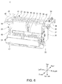
- the second peeling part 24 is disposed pivotably to the first peeling part 23 e.g. on a cover rail 25 at the bottom of the second peeling part 24. More specifically, the second peeling part 24 pivots between a closed position (see FIG. 4 ) closing the front of the first peeling part 23, and an open position (see FIG. 6 ) that opens the front of the first peeling part 23.
- the user may rotate the second peeling part 24 from the closed position to the open position.
- the liner Pa from which the labels Pb are removed is fed between the first peeling part 23 and second peeling part 24 to the inclined panel 16.
- the first peeling part 23 may include a peeler frame 26, a guide mount 27, a peeling member 28, a peeling member support 29, a peeling conveyance motor 31, and a peeling drive roller 32.
- the peeler frame 26 supports the other parts of the first peeling part 23.
- the peeler frame 26 is basically like a box that is open to the top and front.
- the guide mount 27 is for mounting the peeling unit 6 slidably front and back (i.e. in the conveyance direction and opposite the conveyance direction) on the left guide rail 4 and right guide rail 5.
- the guide mount 27 may include a left mount 33, a right mount 34, and a connector 35.
- the connector 35 extends left and right, and connects the left mount 33 and the right mount 34.
- the left mount 33 is fastened to the left top end of the peeler frame 26.
- a left guide engaging part 36 that is U-shaped when seen from the front is disposed to the front end of the left mount 33.
- the left guide engaging part 36 engages the left guide rail 4 from the inside (right side).
- the right mount 34 is fastened to the right top end of the peeler frame 26.
- Right guide engaging parts 37 that are U-shaped when seen from the front are disposed to the front and back ends of the right mount 34.
- the right guide engaging parts 37 engage the right guide rail 5 from the inside (left side).
- a guide roller 38 is disposed on the outside side (right side) of each right guide engaging part 37.
- an endless belt 56 described further below may be fastened to the bottom of the right mount 34.
- a linear detector 59 described further below may be disposed above the right mount 34.
- the peeling member 28 peels a label Pb from the liner Pa. Only the liner Pa part of the label paper P is bent back by the peeling member 28.
- the peeling member 28 is disposed to the top of the peeling member support 29 in front of the connector 35 between the left mount 33 and right mount 34.
- the narrow flat front side of the peeling member 28 is long left to right, and bends 90 degrees or more down.
- the peeling member 28 thus has a peeling edge 39 along the front forming an acute angle.
- the liner Pa is folded back at this peeling edge 39.
- a (substantially vertical) rocking rail (pivoting rail; not shown in the figure) is formed protruding down from the middle of the peeling member 28 between the left and right ends. This rocking rail engages a rocking channel (not shown in the figure) disposed to the top of the peeling member support 29.
- the peeling member 28 can rock (pivot) through a plane substantially parallel to the top of a conveyance surface extending from the holding unit 3 to the peeling member 28, that is, substantially parallel to the top of the peeling member 28.
- the peeling member 28 If the peeling member 28 is stationary and the label paper P is set at an angle to the peeling member 28 as shown in FIG. 8 (a) , the label paper P will lift away from the peeling member 28 and peeling the labels Pb may not be possible. However, because the peeling member 28 in this embodiment of the invention can rock as shown in FIG. 8 (b) , the peeling member 28 will rock and follow the label paper P even if the label paper P is set at an angle to the peeling member 28. As a result, labels Pb can be appropriately peeled from the liner Pa by suppressing separation of the label paper P from the peeling member 28.
- a transverse middle member 41 may be disposed between the peeling member 28 and connector 35.
- a longitudinal middle member 42 may be disposed between the left and right ends of the peeling member 28 and the left mount 33 and right mount 34.
- a gap allowing the peeling member 28 to move is provided between the peeling member 28 and the transverse middle member 41, and between the peeling member 28 and the longitudinal middle members 42.
- the peeling member support 29 is disposed between the left and right walls of the peeler frame 26.
- the rocking channel engaged by the rocking rail may be disposed e.g. in the left-right middle part of the top of the peel ing member support 2 9 as described above.
- a detector window 43 may be opened in the front of the peeling member support 29 in the middle between the left and right ends.
- the detection probe 44 of the slack detector 9 may protrude from the detector window 43.
- the peeling conveyance motor 31 drives the peeling drive roller 32 forward and reverse.
- the peeling conveyance motor 31 is fixed to the inside of the left wall of the peeler frame 26.
- a transmission gear 45 that transfers drive power from the peeling conveyance motor 31 to the peeling drive roller 32 is disposed to the outside of the left wall of the peeler frame 26.
- the peeling drive roller 32 and the driven peeling roller 48 disposed to the second peeling part 24 exemplarily embody a peeling conveyance roller 46, which may be a nip roller unit, for example, that rotates and conveys the label paper P.
- the peeling conveyance roller 46 may be said to function as a conveyance unit for conveying the label paper P.
- the peeling conveyance roller 46 is located on the downstream side of the peeling member 28 on the label paper P conveyance path.
- the peeling conveyance roller 46 can convey the label paper P forward (forward feed) or in reverse (back feed).
- the peeling drive roller 32 extends left and right with the ends supported rotatably by the left wall and right wall of the peeler frame 26.
- the second peeling part 24 may include a peeler cover 47 and the driven peeling roller 48.
- the peeler cover 47 is shaped like a box that is open near the bottom of the back.
- the peeler cover 47 is rotatably attached to the peeler frame 26 by the cover rail 25.
- the label detector 11 may be disposed to the top of the peeler cover 47.
- the driven peeling roller 48 extends left and right, and the ends thereof are rotatably supported by the peeler cover 47.
- the driven peeling roller 48 rotates following the peeling drive roller 32.
- the driven peeling roller 48 and peeling drive roller 32 may be integrated with the peeling member 28 through the peeler frame 26. More specifically, the peeling conveyance roller 46 exemplarily embodied by the peeling drive roller 32 and driven peeling roller 48 may move in unison with the peeling member 28 bi-directionally between the start peeling position and end peeling position. In other words, the conveyance unit may move in unison with the peeling member 28. Therefore, change in the turning angle ⁇ of the liner Pa created by the peeling member 28 and peeling conveyance roller 46 when the peeling member 28 moves to and away from the holding unit 3 can be suppressed (see FIG. 13 (e) ). As a result, labels Pb can be peeled consistently from the liner Pa.
- the peeling unit 6 By feeding the label paper P forward by the peeling conveyance roller 46, the peeling unit 6 thus comprised moves itself from the start peeling position to the end peeling position. More specifically, when the label paper P is held by the holding unit 3 and the label paper P is fed forward by the peeling conveyance roller 46, the label paper P becomes taut. The peeling unit 6 is then pushed by the taut label paper P and moves from the start peeling position to the end peeling position (i. e. towards the holding unit 3) . More specifically, the tension on the label paper P causes the peeling unit 6 to move from the start peeling position to the end peeling position.
- the peeling unit moving unit 7 moves the peeling unit 6 back to the start peeling position.
- the peeling unit moving unit 7 may include a peeling unit moving motor 51, a moving gear 52, a drive pulley 53, two driven pulleys 54, a tension pulley 55, the endless belt 56, and a torque limiter 57.
- the moving gear 52, drive pulley 53, two driven pulleys 54, tension pulley 55, and endless belt 56 exemplarily embody a power transfer mechanism that transfers drive power from the peeling unit moving motor 51 to the peeling unit 6.
- the peeling unit moving motor 51 is the drive source for moving the peeling unit 6 from the end peeling position to the start peeling position.
- the peeling unit moving motor 51 is fastened to the base plate 12.
- the moving gear 52 meshes with the output gear (not shown in the figure) fastened to the output shaft of the peeling unit moving motor 51.
- the drive pulley 53 has teeth, and is fastened coaxially to the right side of the moving gear 52.
- the drive pulley 53 and moving gear 52 are rotatably supported at the bottom of the right panel.
- the two driven pulleys 54 are rotatably supported at the top of the right panel.
- the two driven pulleys 54 are disposed front and back on a line substantially parallel to the right guide rail 5.
- the tension pulley 55 is disposed between the drive pulley 53 and the rear driven pulley 54.
- the tension pulley 55 pushes against the outside surface of the endless belt 56, causing the endless belt 56 to curve around the tension pulley 55 and applying tension to the endless belt 56.
- the endless belt 56 has teeth, and is mounted on the drive pulley 53 and two driven pulleys 54.
- the right mount 34 described above is fastened to the endless belt 56 between the two driven pulleys 54.
- the direction of drive pulley 53 rotation when turning counterclockwise as seen from the right is referred to below as the first direction of rotation Da1, and the direction of rotation when turning clockwise is second direction of rotation Da2.
- the direction of endless belt 56 rotation when travelling counterclockwise as seen from the right is referred to below as the first direction of travel Db1, and the direction of rotation when travelling clockwise is second direction of travel Db2.
- the peeling unit moving motor 51 of the peeling unit moving unit 7 rotationally drives the drive pulley 53 in the first direction of rotation Da1
- the endless belt 56 moves in the first direction of travel Db1
- the peeling unit 6 moves from the end peeling position to the start peeling position (see FIG. 9A ) .
- the peeling unit 6 is pushed by the label paper P and moves from the start peeling position to the end peeling position, i.e. towards the holding unit 3.
- the endless belt 56 travels in the second direction of travel Db2, and the drive pulley 53 turns in the second direction of rotation Da2 (see FIG. 9B ).
- the torque limiter 57 is coaxially connected to the left side of the moving gear 52.
- the torque limiter 57 limits the torque in the second direction of rotation Da2 of the drive pulley 53 to a set torque limit.
- the linear encoder 8 detects the position of the peeling unit 6 on the front-back axis.
- the linear encoder 8 includes a linear scale 58 and linear detector 59.
- the linear scale 58 is disposed above the right guide rail 5 and substantially parallel to the right guide rail 5. More specifically, the linear scale 58 extends between the start peeling position and end peeling position.
- the linear scale 58 has a scale of slits (not shown in the figure) .
- the linear detector 59 is disposed to the top of the right mount 34.
- a photo interrupter for example, may be used as the linear detector 59.
- the linear encoder 8 outputs a pulse signal to a controller 60 in conjunction with movement of the peeling unit 6.
- the slack detector 9 detects slack in the label paper P between the peeling member 28 and peeling drive roller 32.
- a microswitch for example, may be used as the slack detector 9.
- the detection probe 44 of the slack detector 9 protrudes from the detector window 43 as described above.
- the detection probe 44 When the slack in the label paper P between the peeling member 28 and peeling drive roller 32 is less than a specific amount, the detection probe 44 is pushed by the label paper P and recedes into the detector window 43, and the slack detector 9 turns on. That there is less than the specific amount of slack in the label paper P, or more specifically that there is no slack in the label paper P, is thus detected.
- the detection probe 44 protrudes from the detector window 43, and the slack detector 9 turns off. That the slack in the label paper P exceeds the limit, or more specifically that there is slack in the label paper P, is thus detected.
- the label detector 11 detects if a label Pb has been removed from the liner Pa.
- the label detector 11 is disposed to the top of the peeler cover 47 in the middle between the left and right ends.
- a reflective photo interrupter for example, may be used as the label detector 11.
- the label detector 11 outputs a Low signal to the controller 60 described further below when a label Pb is left on the liner Pa. If the label Pb has been removed from the liner Pa, the label detector 11 outputs a High signal (exemplarily embodying a signal indicating that the label Pb has been removed from the liner Pa) to the controller 60.
- the Low and High output states of the detection signal may obviously be reversed.
- the label peeling device 1 has a controller 60 and a communication unit 70.
- the communication unit 70 is communicatively connected between the controller 60 and an external device such as the label printer 100, for example.
- the communication unit 70 receives and supplies data from the external device to the controller 60.
- the controller 60 includes a CPU (central processing unit) and memory.
- the gripping motor 21, peeling conveyance motor 31, and peeling unit moving motor 51 are connected through drivers (not shown) to the output side of the controller 60.
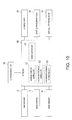
- the controller 60 functionally includes a peeling distance setting unit 61, a movement distance setting unit 62, a movement distance computing unit 63, and a motor control unit 64. These function units are embodied by the cooperation of the hardware of the controller 60 and software stored in memory.
- the peeling distance setting unit 61 sets a peeling distance A.
- the movement distance setting unit 62 sets a peeling unit movement distance C by adding a specific additional distance B to the peeling distance A.
- peeling distance A additional distance B
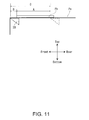
- peeling unit movement distance C are described next with reference to FIG. 11 .
- the peeling distance A is the distance at which a label Pb separates from the liner Pa in the lengthwise direction of the label paper P.
- the peeling distance setting unit 61 may set the peeling distance A based on the length of the label Pb acquired from the label printer 100, or based on a value input by the user, for example. Note that peeling distance A is preferably slightly shorter than the length of the label Pb in the conveyance direction.
- the additional distance B is equal to the distance between the peeling member 28 when the peeling unit 6 is at the start peeling position, and the downstream end of the label Pb. More specifically, the peeling member 28 starts moving from the position additional distance B downstream from the downstream end of the label Pb. Note that the additional distance B maybe 0 mm, but is preferably several millimeters so that peeling starts reliably from the downstream end of the label Pb.
- the peeling unit movement distance C is the distance between the start peeling position and the end peeling position of the peeling unit 6.
- the peeling unit movement distance C corresponds to (e.g. is determined as) the sum of the peeling distance A and the additional distance B.
- the movement distance computing unit 63 calculates the position from the peeling unit 6 to the start peeling position or the end peeling position, that is, the distance the peeling unit 6 has moved.
- the motor control unit 64 controls driving the gripping motor 21, peeling conveyance motor 31, and peeling unit moving motor 51.
- the motor control unit 64 moves the peeling unit 6 by the peeling unit movement distance C set by the movement distance setting unit 62.
- the motor control unit 64 therefore controls driving the peeling conveyance motor 31 based on the movement distance of the peeling unit 6 output from the movement distance computing unit 63.
- the peeling unit 6 can be moved from the start peeling position to the end peeling position according to the peeling unit movement distance C that was set.
- the peeling unit 6 therefore moves from the start peeling position to the end peeling position according to the length of the label Pb when the peeling distance setting unit 61 sets the peeling distance A based on the length of the label Pb.
- the amount corresponding to the length of the label Pb can therefore be peeled.
- the motor control unit 64 moves the peeling unit 6 the peeling unit movement distance C set by the movement distance setting unit 62.
- the motor control unit 64 therefore controls driving the peeling unit moving motor 51 based on the movement distance of the peeling unit 6 outputs from the movement distance computing unit 63.
- the peeling unit 6 can be moved from the end peeling position to the start peeling position according to the peeling unit movement distance C that was set.
- the peeling unit 6 therefore moves from the end peeling position to the start peeling position according to the length of the label Pb when the peeling distance setting unit 61 sets the peeling distance A based on the length of the label Pb. For example, when the length of the label Pb is long, the start peeling position moves to a position further forward.
- start peeling position may be fixed and the end peeling position changed according to the peeling unit movement distance C, or both the start peeling position and the end peeling position may change according to the peeling unit movement distance C.
- the motor control unit 64 blocks driving the peeling unit moving motor 51. More specifically, the motor control unit 64 prevents driving peeling unit moving motor 51 after the peeling unit 6 moves from the start peeling position to the end peeling position if the label Pb has not been peeled from the liner Pa. This prevents a label Pb that was peeled from the liner Pa from sticking to the liner Pa again. If the label detector 11 outputs a High signal, that is, the label Pb was removed from the liner Pa, the motor control unit 64 enables driving the peeling unit moving motor 51.
- the motor control unit 64 also controls the peeling conveyance motor 31 based on the output of the slack detector 9.
- the operation of the label peeling device 1 for peeling a label Pb from the liner Pa e.g. after an image has been printed on the label Pb by the label printer 100 is described next with reference to FIG. 12 and FIG. 13 .
- FIG. 12 (a) shows a label Pb to be printed when positioned to the recording head 112.
- the holding unit 3 of the label peeling device 1 is in the release position.
- the peeling unit 6 is in the start peeling position.
- the label printer 100 ejects ink from the recording head 112 to record an image on the label Pb while conveying the label paper P with the paper feed roller 109 as shown in FIG. 12 (b) .
- the label peeling device 1 conveys the label paper P with slack by the peeling conveyance roller 46.
- the paper feed roller 109 and peeling conveyance roller 46 convey the label paper P forward with slack until the label Pb with the recorded image reaches the peeling position.
- the peeling position is the position where the downstream end of the label Pb is the additional distance B upstream from the peeling member 28 (i.e. from the peeling edge 39 of the peeling member 28) .
- the holding unit 3 goes to the holding position and the label paper P is held by the holding unit 3.
- the peeling conveyance roller 46 feeds the label paper P by the peeling unit movement distance C while the label paper P is kept taut as shown in FIG. 13 (e) .
- the peeling unit 6 moves from the start peeling position to the end peeling position.
- the label Pb is peeled for the peeling distance A from the downstream end of the label Pb.
- the upstream end of the label Pb remains affixed to the liner Pa (e.g. if the peeling distance A is chosen slightly shorter than the length of the label Pb).
- the label Pb may be removed from the liner Pa by the user.
- the user can therefore get a label Pb that has been desirably printed.
- the label detector 11 outputs a High signal to the controller 60.
- the motor control unit 64 allows driving the peeling unit moving motor 51 again.
- the peeling unit moving unit 7 moves the peeling unit 6 by the peeling unit movement distance C from the end peeling position to the start peeling position while reversing the label paper P with the peeling conveyance roller 46.
- the distance by which the label paper P is fed at this time is sufficient to assure that there is slack in the label paper P even after the peeling unit 6 returns to the start peeling position.
- the peeling conveyance roller 46 reversing the label paper P simultaneously to the peeling unit 6 moving from the end pee ling posit ion to the start pee ling posit ion, the peeling unit 6 can move smoothly without interference from the label paper P even if the label paper P is still held by the holding unit 3 when the peeling unit 6 moves from the end peeling position to the start peeling position. Note that there is no need for the label paper P to be reversed simultaneously to the peeling unit 6 moving from the end peeling position to the start peeling position, and the peeling unit 6 may be moved after the label paper P has been reversed.
- the holding unit 3 is moved to the release position by driving the gripping motor 21 and moving the gripping member 19 to the release position.
- the label paper P is then reversed with slack therein by the paper feed roller 109 and peeling conveyance roller 46 until the next label Pb reaches the start printing position. This completes the complete operating sequence for printing and peeling one label Pb.
- the label peeling device 1 conveys the label paper P with slack.
- creating a difference between the actual conveyance distance of the label paper P and the rotational feed distance of the paper feed roller 109, that is, the outside circumference of the paper feed roller 109 multiplied by the number of paper feed roller 109 revolutions, can be suppressed. This is described further below.
- the label paper P is conveyed forward with the rotational conveyance speed Vpe of the peeling conveyance roller 46 greater than the rotational conveyance speed Vpf of the paper feed roller 109.
- the slack in the label paper P decreases between the paper feed roller 109 and peeling conveyance roller 46.
- the rotational conveyance speed Vpf of the paper feed roller 109 is the product of the outside circumference of the paper feed roller 109 multiplied by the rotational speed of the paper feed roller 109.
- the rotational conveyance speed Vpe of the peeling conveyance roller 46 is the product of the outside circumference of the peeling conveyance roller 46 multiplied by the rotational speed of the peeling conveyance roller 46.
- a specific amount or more of slack can therefore be constantly maintained by repeating this process.
- the actual conveyance of the label paper P becoming greater than the rotational conveyance distance of the paper feed roller 109 during forward conveyance can therefore be suppressed.
- the label paper P is conveyed in reverse with the rotational conveyance speed Vpe of the peeling conveyance roller 46 greater than the rotational conveyance speed Vpf of the paper feed roller 109.
- the slack in the label paper P increases between the paper feed roller 109 and peeling conveyance roller 46.
- the slack detector 9 turns off and slack in the label paper P is detected.
- the motor control unit 64 stops driving the peeling conveyance roller 46 after a delay, that is, after waiting a specific time. As a result, the peeling conveyance roller 46 stops back feeding the label paper P. The paper feed roller 109 continues turning at this time. As a result, the slack in the label paper P decreases.
- the peeling unit 6 moves from the start peeling position to the end peeling position by being pushed by the label paper P according to the conveyance speed of the label paper P by the peeling conveyance roller 46. Therefore, the peeling member 28 separating from the label paper P is suppressed, and excess slack developing in the label paper P is suppressed. As a result, the label paper P can be reliably folded back by the peeling member 28. In addition, the labels Pb can be reliably peeled from the liner Pa.
- the label peeling device 1 may be incorporated in the label printer 100. More specifically, the label printer 100 may be configured with the holding unit 3, peeling unit 6, and other parts of the label peeling device 1.
- the fluid ejection device is also not limited to one that ejects ink, and may eject any desirable fluid, including coating agents and other types of fluids.
Landscapes
- Labeling Devices (AREA)
- Folding Of Thin Sheet-Like Materials, Special Discharging Devices, And Others (AREA)
- Ink Jet (AREA)
Abstract
Description
- The present disclosure relates to a label peeling device that separates the labels from the liner backing of label paper.
- Label peeling devices that have a take-up roller for rewinding label paper conveyed from a label printer, a motor that drives the take-up roller, a peeling plate disposed between the label printer and the take-up roller to peel labels from the liner backing by bending the liner, an air cylinder that moves the peeling plate forward and back in the conveyance direction of the label paper, and a suction pad that holds the printing surface of the label, are known from the literature. When the printing surface of a label is held by the suction pad, this label peeling device separates the label from the liner by the air cylinder moving the peeling plate toward the label printer while rewinding the liner onto the take-up roller. See, for example,
JP-A-2009-012851 - When the peeling member is moved by an air cylinder while rewinding the label paper by driving a motor as in the label peeling device described in
JP-A-2009-012851 - In view of the above problem, the present invention provides a label peeling device, a fluid ejection device, and a peeling method, having the features of the respective independent claims.
- In some embodiments, a label peeling device has a peeling unit that peels labels from label paper fed from a fluid ejection device that ejects fluid onto the label paper, the label paper including labels and a liner to which the labels are affixed. The peeling unit includes: a peeling member is configured to move bi-directionally between a start peeling position and an end peeling position, and fold back the liner portion of the label paper; and a conveyance unit that is disposed to the conveyance path of the label paper downstream from the peeling member and conveys the label paper. The peeling member is configured to move between the start peeling position and the end peeling position.
- In some embodiments, a fluid ejection device includes: a fluid ejection unit that ejects fluid onto label paper, the label paper including labels and a liner to which the labels are affixed; and a peeling unit that is disposed to the label paper conveyance path and peels labels from label paper. The peeling unit includes a peeling member that is configured to move between a start peeling position and an end peeling position, and fold back the liner; and a conveyance unit that is disposed to the label paper conveyance path downstream from the peeling member and conveys the label paper. The peeling member is configured to move between the start peeling position and the end peeling position. The fluid ejection device may include the label peeling device described above.
- Some embodiments relate to a peeling method of a label peeling device having a peeling member that peels labels from label paper fed from a fluid ejection device that ejects fluid onto the label paper, the label paper including labels and a liner to which the labels are affixed, and a conveyance unit that is disposed downstream from the peeling member and conveys the label paper. The peeling method includes moving the peeling member from the start peeling position to the end peeling position to peel the labels from the liner.
-
-
FIG. 1 is an oblique view of an example of a label peeling device according to a preferred embodiment of the invention when not installed to the label printer. -
FIG. 2 is an oblique view of the example of the label peeling device when installed to the label printer. -
FIG. 3 illustrates an example of the configuration of the label peeling device and label printer. -
FIG. 4 is an oblique view of the example of the label peeling device. -
FIG. 5 is a section view of the example of the label peeling device. -
FIG. 6 is an oblique view of an example of a peeling unit of the label peeling device. -
FIG. 7 is an oblique view of the example of the peeling unit from a different angle than inFIG. 6 . -
FIG. 8A and FIG. 8B are oblique views exemplarily describing the rocking action of a peeling member of the peeling unit. -
FIG. 9A exemplarily illustrates operation of the peeling unit moving unit when the peeling unit moves from the end peeling position to the start peeling position, andFIG. 9B exemplarily illustrates operation of the peeling unit moving unit when the peeling unit moves from the start peeling position to the end peeling position. -
FIG. 10 is a block diagram of an example of a control system of the label peeling device. -
FIG. 11 is used to exemplarily describe the peeling distance, additional distance, and peeling unit movement distance. -
FIG. 12 exemplarily illustrates the operation that peels a label from the liner in a label peeling device after recording an image on the label in a label printer. -
FIG. 13 continues exemplary illustration of the operation shown inFIG. 12 of peeling a label from the liner in a label peeling device after recording an image on the label in a label printer. -
FIG. 14 exemplarily illustrates the operation controlling the peeling feed roller based on output from a slack detector when feeding the label paper forward. -
FIG. 15 exemplarily illustrates the operation controlling the peeling feed roller based on output from a slack detector when feeding the label paper in reverse. - Exemplary embodiments of a label peeling device according to the present invention are described below with reference to the accompanying figures.
- Note that the disclosure is described using the directions top, bottom, left, right, front, and rear as shown in the figures, but these directions are for descriptive convenience only, and the invention is obviously not limited to these directions.
- As shown in
FIG. 1 to FIG. 3 , alabel peeling device 1 according to the invention may be used installed to the front of thelabel printer 100, or more particularly to the paper exit side of thelabel printer 100. Thelabel printer 100 is therefore described first below. - Based on image data e.g. received from a communicatively connected computer (not shown in the figure), the
label printer 100 records images on the label paper P using an inkjet printhead. Note that thelabel printer 100 can also be used without thelabel peeling device 1 installed. Thelabel peeling device 1 may therefore be installed to thelabel printer 100 as an optional device. - The label paper P has a continuous liner (such as a web liner, for example) Pa, and multiple labels Pb affixed to the liner Pa with a substantially equal gap between adjacent labels Pb. The liner Pa and labels Pb are not limited to any particular type of material. The label paper P in this embodiment is provided as roll paper R, but is not so limited and may be fanfold paper, for example.
- The
label printer 100 has a basically rectangular box-like case 101. Aroll paper cover 102, discharge table 103,release lever 104,power switch 105,operating panel 106, andink cartridge cover 107 may be disposed to the front of thecase 101 where the paper exit is located. A rollpaper supply unit 108,paper feed roller 109,platen 111, and recordinghead 112 may be disposed inside thecase 101. - The
recording head 112 in this example is an example of a fluid ejection unit. - The
roll paper cover 102 is normally locked in a position covering the front of the rollpaper supply unit 108. To replace the roll paper R, for example, the user may work the release lever 104 to unlock theroll paper cover 102. As a result, the user may rotate theroll paper cover 102 together with the discharge table 103 and release lever 104 forward pivoting at the bottom of theroll paper cover 102, and thereby open the rollpaper supply unit 108. - If the
label peeling device 1 is not installed, the discharge table 103 functions as a support for receiving the discharged label paper P. If thelabel peeling device 1 is installed, the discharged label paper P is not received by the discharge table 103 , and is instead passed to thelabel peelingdevice 1. The discharge table 103 is basically trapezoidal when seen from the side, and may engage a table receiving part 17 (described further below) of thelabel peeling device 1. - The roll paper R is loaded into the roll
paper supply unit 108. Thepaper feed roller 109 may be a nip roller, for example. Thepaper feed roller 109 feeds the label paper P forward, that is, pulls the label paper P from the rollpaper supply unit 108 and conveys it toward the recording head 112 (exemplarily embodying a fluid ejection unit) . Thepaper feed roller 109 can also back feed the label paper P, that is, convey the label paper P back into the rollpaper supply unit 108. Therecording head 112 may have a plurality of inkjet heads for multiple colors of ink, such as the four CMYK colors, for example. Therecording head 112 ejects ink and may record color images on the labels Pb of the label paper P conveyed over theplaten 111. After passing therecording head 112, the label paper P is conveyed to thelabel peeling device 1 installed to the front of thelabel printer 100. - The
label peeling device 1 is described next. Thelabel peeling device 1 peels the labels Pb from the liner Pa of the label paper P conveyed e.g. from thelabel printer 100. Notably, thelabel peeling device 1 may be employed for peeling the labels Pb from the liner Pa of label paper P conveyed from any source for conveying the label paper, including, but not being limited to, thelabel printer 100. - As shown in
FIG. 4 andFIG. 5 , thelabel peeling device 1 may have asupport base 2, holdingunit 3,left guide rail 4,right guide rail 5, peelingunit 6, peelingunit moving unit 7,linear encoder 8,slack detector 9, andlabel detector 11. - Note that the
peeling unit 6 is an example of the peeling unit in the accompanying claims, and the peelingunit moving unit 7 is an example of a return unit. - The
support base 2 supports other parts of thelabel peeling device 1. Thesupport base 2 may include abase plate 12, leftpanel 13, a right panel (not shown in the figure), aback panel 15, and aninclined panel 16. - The
base plate 12 is substantially rectangular. Theleft panel 13 and the right panel are affixed to the left and right edge areas of thebase plate 12. Theleft panel 13 and the right panel are also substantially rectangular. - The
table receiving part 17 is formed as a substantially trapezoidal notch in the top of the back end of theleft panel 13 and right panel. When thelabel peeling device 1 is installed to thelabel printer 100, thetable receiving part 17 accepts the left and right sides of the discharge table 103. Adrive pulley 53 and drivenpulleys 54 are rotatably supported by the right panel. - The
inclined panel 16 is disposed between theleft panel 13 and right panel at an angle descending toward the front of thelabel peeling device 1. After the labels Pb are removed by thepeeling unit 6, the liner Pa is received by theinclined panel 16 and is fed at an angle descending toward the front along the top of theinclined panel 16. - The holding
unit 3 has a holding position where it holds the label paper P conveyed from thelabel printer 100, and a release position where it does not hold the label paper P. The holdingunit 3 may include asupport pedestal 18, a grippingmember 19, and a gripping motor 21 (seeFIG. 10 ). - The
support pedestal 18 may be attached to the top back part of theleft panel 13 and right panel spanning the gap between theleft panel 13 and right panel. The grippingmember 19 may be disposed substantially in the middle between the left and right ends of thesupport pedestal 18, and is substantially rectangular and long left to right. The grippingmember 19 can move to and away from thesupport pedestal 18 between a holding position (FIG. 12 (d) ) where the label paper P is held with the support pedestal 18 (i.e. the label paper is pinched between the grippingmember 19 and the support pedestal 18), and a release position (FIG. 12 (a) to (c) ) where the label paper P is not held. Accordingly, the holdingunit 3 may be said to be movable between the holding position in which the label paper P is held (e.g. pinched) by the holdingunit 3, and a release position in which the label paper P is not held (e.g. pinched) by the holding unit. - The
gripping motor 21 is the drive source for moving the grippingmember 19 between the holding position and the release position. Note that an air cylinder, solenoid, or other drive means other than a motor may be used as the drive source that moves the grippingmember 19 between the holding position and the release position. The user may also manually move the grippingmember 19 between the holding position and release position. Thus, thegripping motor 21 may be said to be an example of an actuation unit for moving the holdingunit 3 between the holding position and the release position, i.e. for moving the grippingmember 19 between the holding position and the release position. - The
left guide rail 4 andright guide rail 5 extend on the front-rear axis, and guide movement of thepeeling unit 6 between the front and back. The front end of theleft guide rail 4 is supported by theleft panel 13 through asupport bracket 22, and the back end of theleft guide rail 4 is supported by theleft panel 13 through thesupport pedestal 18. The front end of theright guide rail 5 is likewise supported by the right panel through anothersupport bracket 22, and the back end of theright guide rail 5 is supported by the right panel through thesupport pedestal 18. - The
peeling unit 6 peels the labels Pb from the liner Pa of the label paper P conveyed from e.g. thelabel printer 100. Thepeeling unit 6 is disposed in front of the holdingunit 3, that is, downstream from the holdingunit 3 on the conveyance path of the label paper P. Note that upstream and downstream as used herein are referenced to the normal forward conveyance direction of the label paper P. - The
peeling unit 6 can move bi-directionally between a start peeling position (FIG. 12 (a) to (d) ) separated from the holdingunit 3, and an end peeling position (FIG. 13 (e) and (f) ) near the holdingunit 3. Thepeeling unit 6 peels the labels Pb from the liner Pa by moving from the start peeling position to the end peeling position while the label paper P is held by the holdingunit 3. In other words, thepeeling unit 6 peels the labels Pb from the liner Pa by moving towards the holdingunit 3 while the holdingunit 3 is in the holding position and holds the label paper P. As a result, the labels Pb are peeled from the liner Pa from the downstream side to the upstream side of the label paper P conveyance path. - Note that the end peeling position is fixed in this embodiment, and the start peeling position moves according to the peeling unit movement distance C described below.
- As shown in
FIG. 4 to FIG. 7 , thepeeling unit 6 may include afirst peeling part 23 and asecond peeling part 24. Thesecond peeling part 24 is disposed pivotably to the first peelingpart 23 e.g. on acover rail 25 at the bottom of thesecond peeling part 24. More specifically, thesecond peeling part 24 pivots between a closed position (seeFIG. 4 ) closing the front of the first peelingpart 23, and an open position (seeFIG. 6 ) that opens the front of the first peelingpart 23. When setting the label paper P in thepeeling unit 6, the user may rotate thesecond peeling part 24 from the closed position to the open position. The user then may insert the leading end of the label paper P between the peeling drive roller 32 (described further below) of the first peelingpart 23, and the driven peeling roller 48 (described further below) of thesecond peeling part 24. The user then may return thesecond peeling part 24 to the closed position. This loads the label paper P in thepeeling unit 6. The liner Pa from which the labels Pb are removed is fed between the first peelingpart 23 and second peelingpart 24 to theinclined panel 16. - The
first peeling part 23 may include apeeler frame 26, aguide mount 27, a peelingmember 28, a peelingmember support 29, a peelingconveyance motor 31, and a peelingdrive roller 32. - The
peeler frame 26 supports the other parts of the first peelingpart 23. Thepeeler frame 26 is basically like a box that is open to the top and front. - The
guide mount 27 is for mounting thepeeling unit 6 slidably front and back (i.e. in the conveyance direction and opposite the conveyance direction) on theleft guide rail 4 andright guide rail 5. The guide mount 27 may include aleft mount 33, aright mount 34, and aconnector 35. Theconnector 35 extends left and right, and connects theleft mount 33 and theright mount 34. - The
left mount 33 is fastened to the left top end of thepeeler frame 26. A leftguide engaging part 36 that is U-shaped when seen from the front is disposed to the front end of theleft mount 33. The leftguide engaging part 36 engages theleft guide rail 4 from the inside (right side). - The
right mount 34 is fastened to the right top end of thepeeler frame 26. Rightguide engaging parts 37 that are U-shaped when seen from the front are disposed to the front and back ends of theright mount 34. The rightguide engaging parts 37 engage theright guide rail 5 from the inside (left side). - A
guide roller 38 is disposed on the outside side (right side) of each rightguide engaging part 37. When the leftguide engaging part 36 and rightguide engaging parts 37 are respectively engaged with theleft guide rail 4 andright guide rail 5, and thepeeling unit 6 moves between the front and back, theguide rollers 38 roll along the outside (right side) of theright guide rail 5. - Note than an
endless belt 56 described further below may be fastened to the bottom of theright mount 34. Alinear detector 59 described further below may be disposed above theright mount 34. - When the
peeling unit 6 moves from the start peeling position to the end peeling position, the peelingmember 28 peels a label Pb from the liner Pa. Only the liner Pa part of the label paper P is bent back by the peelingmember 28. The peelingmember 28 is disposed to the top of the peelingmember support 29 in front of theconnector 35 between theleft mount 33 andright mount 34. - The narrow flat front side of the peeling
member 28 is long left to right, and bends 90 degrees or more down. The peelingmember 28 thus has a peelingedge 39 along the front forming an acute angle. - The liner Pa is folded back at this peeling
edge 39. A (substantially vertical) rocking rail (pivoting rail; not shown in the figure) is formed protruding down from the middle of the peelingmember 28 between the left and right ends. This rocking rail engages a rocking channel (not shown in the figure) disposed to the top of the peelingmember support 29. As a result, the peelingmember 28 can rock (pivot) through a plane substantially parallel to the top of a conveyance surface extending from the holdingunit 3 to the peelingmember 28, that is, substantially parallel to the top of the peelingmember 28. - If the peeling
member 28 is stationary and the label paper P is set at an angle to the peelingmember 28 as shown inFIG. 8 (a) , the label paper P will lift away from the peelingmember 28 and peeling the labels Pb may not be possible. However, because the peelingmember 28 in this embodiment of the invention can rock as shown inFIG. 8 (b) , the peelingmember 28 will rock and follow the label paper P even if the label paper P is set at an angle to the peelingmember 28. As a result, labels Pb can be appropriately peeled from the liner Pa by suppressing separation of the label paper P from the peelingmember 28. - A transverse
middle member 41 may be disposed between the peelingmember 28 andconnector 35. A longitudinalmiddle member 42 may be disposed between the left and right ends of the peelingmember 28 and theleft mount 33 andright mount 34. A gap allowing the peelingmember 28 to move is provided between the peelingmember 28 and the transversemiddle member 41, and between the peelingmember 28 and the longitudinalmiddle members 42. - The peeling
member support 29 is disposed between the left and right walls of thepeeler frame 26. The rocking channel engaged by the rocking rail may be disposed e.g. in the left-right middle part of the top of the peeling member support 2 9 as described above. Adetector window 43 may be opened in the front of the peelingmember support 29 in the middle between the left and right ends. Thedetection probe 44 of theslack detector 9 may protrude from thedetector window 43. - The peeling
conveyance motor 31 drives the peelingdrive roller 32 forward and reverse. The peelingconveyance motor 31 is fixed to the inside of the left wall of thepeeler frame 26. Atransmission gear 45 that transfers drive power from the peelingconveyance motor 31 to the peelingdrive roller 32 is disposed to the outside of the left wall of thepeeler frame 26. - The peeling
drive roller 32 and the driven peelingroller 48 disposed to thesecond peeling part 24 exemplarily embody a peelingconveyance roller 46, which may be a nip roller unit, for example, that rotates and conveys the label paper P. The peelingconveyance roller 46 may be said to function as a conveyance unit for conveying the label paper P. - The peeling
conveyance roller 46 is located on the downstream side of the peelingmember 28 on the label paper P conveyance path. The peelingconveyance roller 46 can convey the label paper P forward (forward feed) or in reverse (back feed). The peelingdrive roller 32 extends left and right with the ends supported rotatably by the left wall and right wall of thepeeler frame 26. - The
second peeling part 24 may include apeeler cover 47 and the driven peelingroller 48. - The
peeler cover 47 is shaped like a box that is open near the bottom of the back. Thepeeler cover 47 is rotatably attached to thepeeler frame 26 by thecover rail 25. - The
label detector 11 may be disposed to the top of thepeeler cover 47. - The driven peeling
roller 48 extends left and right, and the ends thereof are rotatably supported by thepeeler cover 47. The driven peelingroller 48 rotates following the peelingdrive roller 32. - The driven peeling
roller 48 and peelingdrive roller 32 may be integrated with the peelingmember 28 through thepeeler frame 26. More specifically, the peelingconveyance roller 46 exemplarily embodied by the peelingdrive roller 32 and driven peelingroller 48 may move in unison with the peelingmember 28 bi-directionally between the start peeling position and end peeling position. In other words, the conveyance unit may move in unison with the peelingmember 28. Therefore, change in the turning angle θ of the liner Pa created by the peelingmember 28 and peelingconveyance roller 46 when the peelingmember 28 moves to and away from the holdingunit 3 can be suppressed (seeFIG. 13 (e) ). As a result, labels Pb can be peeled consistently from the liner Pa. - By feeding the label paper P forward by the peeling
conveyance roller 46, thepeeling unit 6 thus comprised moves itself from the start peeling position to the end peeling position. More specifically, when the label paper P is held by the holdingunit 3 and the label paper P is fed forward by the peelingconveyance roller 46, the label paper P becomes taut. Thepeeling unit 6 is then pushed by the taut label paper P and moves from the start peeling position to the end peeling position (i. e. towards the holding unit 3) . More specifically, the tension on the label paper P causes thepeeling unit 6 to move from the start peeling position to the end peeling position. - After the
peeling unit 6 has moved to the end peeling position, the peelingunit moving unit 7 moves thepeeling unit 6 back to the start peeling position. - The peeling
unit moving unit 7 may include a peelingunit moving motor 51, a movinggear 52, adrive pulley 53, two drivenpulleys 54, atension pulley 55, theendless belt 56, and atorque limiter 57. The movinggear 52, drivepulley 53, two drivenpulleys 54,tension pulley 55, andendless belt 56 exemplarily embody a power transfer mechanism that transfers drive power from the peelingunit moving motor 51 to thepeeling unit 6. - The peeling
unit moving motor 51 is the drive source for moving thepeeling unit 6 from the end peeling position to the start peeling position. The peelingunit moving motor 51 is fastened to thebase plate 12. The movinggear 52 meshes with the output gear (not shown in the figure) fastened to the output shaft of the peelingunit moving motor 51. - The
drive pulley 53 has teeth, and is fastened coaxially to the right side of the movinggear 52. Thedrive pulley 53 and movinggear 52 are rotatably supported at the bottom of the right panel. - The two driven
pulleys 54 are rotatably supported at the top of the right panel. The two drivenpulleys 54 are disposed front and back on a line substantially parallel to theright guide rail 5. - The
tension pulley 55 is disposed between thedrive pulley 53 and the rear drivenpulley 54. Thetension pulley 55 pushes against the outside surface of theendless belt 56, causing theendless belt 56 to curve around thetension pulley 55 and applying tension to theendless belt 56. - The
endless belt 56 has teeth, and is mounted on thedrive pulley 53 and two drivenpulleys 54. Theright mount 34 described above is fastened to theendless belt 56 between the two drivenpulleys 54. - As shown in
FIG. 9 , the direction ofdrive pulley 53 rotation when turning counterclockwise as seen from the right is referred to below as the first direction of rotation Da1, and the direction of rotation when turning clockwise is second direction of rotation Da2. Likewise, the direction ofendless belt 56 rotation when travelling counterclockwise as seen from the right is referred to below as the first direction of travel Db1, and the direction of rotation when travelling clockwise is second direction of travel Db2. - When the peeling
unit moving motor 51 of the peelingunit moving unit 7 rotationally drives thedrive pulley 53 in the first direction of rotation Da1, theendless belt 56 moves in the first direction of travel Db1, and thepeeling unit 6 moves from the end peeling position to the start peeling position (seeFIG. 9A ) . As described above, when the label paper P is held by the holdingunit 3 and the peelingconveyance motor 31 conveys the label paper P forward, thepeeling unit 6 is pushed by the label paper P and moves from the start peeling position to the end peeling position, i.e. towards the holdingunit 3. At this time, theendless belt 56 travels in the second direction of travel Db2, and thedrive pulley 53 turns in the second direction of rotation Da2 (seeFIG. 9B ). - The
torque limiter 57 is coaxially connected to the left side of the movinggear 52. Thetorque limiter 57 limits the torque in the second direction of rotation Da2 of thedrive pulley 53 to a set torque limit. As a result, when thepeeling unit 6 moves from the start peeling position to the end peeling position, a substantially constant load is applied to thepeeling unit 6. Tension corresponding to the load applied to thepeeling unit 6 by thetorque limiter 57 is therefore applied to the label paper P folded back by the peelingmember 28. As a result, the label paper P can be appropriately folded back by the peelingmember 28. - The
linear encoder 8 detects the position of thepeeling unit 6 on the front-back axis. Thelinear encoder 8 includes alinear scale 58 andlinear detector 59. Thelinear scale 58 is disposed above theright guide rail 5 and substantially parallel to theright guide rail 5. More specifically, thelinear scale 58 extends between the start peeling position and end peeling position. - The
linear scale 58 has a scale of slits (not shown in the figure) . Thelinear detector 59 is disposed to the top of theright mount 34. A photo interrupter, for example, may be used as thelinear detector 59. Thelinear encoder 8 outputs a pulse signal to acontroller 60 in conjunction with movement of thepeeling unit 6. - The
slack detector 9 detects slack in the label paper P between the peelingmember 28 and peelingdrive roller 32. A microswitch, for example, may be used as theslack detector 9. Thedetection probe 44 of theslack detector 9 protrudes from thedetector window 43 as described above. - When the slack in the label paper P between the peeling
member 28 and peelingdrive roller 32 is less than a specific amount, thedetection probe 44 is pushed by the label paper P and recedes into thedetector window 43, and theslack detector 9 turns on. That there is less than the specific amount of slack in the label paper P, or more specifically that there is no slack in the label paper P, is thus detected. - However, if the slack in the label paper P between the peeling
member 28 and peelingdrive roller 32 exceeds this specific amount, thedetection probe 44 protrudes from thedetector window 43, and theslack detector 9 turns off. That the slack in the label paper P exceeds the limit, or more specifically that there is slack in the label paper P, is thus detected. - The
label detector 11 detects if a label Pb has been removed from the liner Pa. Thelabel detector 11 is disposed to the top of thepeeler cover 47 in the middle between the left and right ends. A reflective photo interrupter, for example, may be used as thelabel detector 11. Thelabel detector 11 outputs a Low signal to thecontroller 60 described further below when a label Pb is left on the liner Pa. If the label Pb has been removed from the liner Pa, thelabel detector 11 outputs a High signal (exemplarily embodying a signal indicating that the label Pb has been removed from the liner Pa) to thecontroller 60. The Low and High output states of the detection signal may obviously be reversed. - An example of the control system of the
label peeling device 1 according to this embodiment is described next with reference toFIG. 10 . As shown inFIG. 10 , thelabel peeling device 1 has acontroller 60 and acommunication unit 70. - The
communication unit 70 is communicatively connected between thecontroller 60 and an external device such as thelabel printer 100, for example. Thecommunication unit 70 receives and supplies data from the external device to thecontroller 60. - The
controller 60 includes a CPU (central processing unit) and memory. Thegripping motor 21, peelingconveyance motor 31, and peelingunit moving motor 51 are connected through drivers (not shown) to the output side of thecontroller 60. - The
controller 60 functionally includes a peelingdistance setting unit 61, a movementdistance setting unit 62, a movementdistance computing unit 63, and amotor control unit 64. These function units are embodied by the cooperation of the hardware of thecontroller 60 and software stored in memory. - The peeling
distance setting unit 61 sets a peeling distance A. The movementdistance setting unit 62 sets a peeling unit movement distance C by adding a specific additional distance B to the peeling distance A. - The peeling distance A, additional distance B, and peeling unit movement distance C are described next with reference to
FIG. 11 . - The peeling distance A is the distance at which a label Pb separates from the liner Pa in the lengthwise direction of the label paper P. The peeling
distance setting unit 61 may set the peeling distance A based on the length of the label Pb acquired from thelabel printer 100, or based on a value input by the user, for example. Note that peeling distance A is preferably slightly shorter than the length of the label Pb in the conveyance direction. - The additional distance B is equal to the distance between the peeling
member 28 when thepeeling unit 6 is at the start peeling position, and the downstream end of the label Pb. More specifically, the peelingmember 28 starts moving from the position additional distance B downstream from the downstream end of the label Pb. Note that the additional distance B maybe 0 mm, but is preferably several millimeters so that peeling starts reliably from the downstream end of the label Pb. - The peeling unit movement distance C is the distance between the start peeling position and the end peeling position of the
peeling unit 6. The peeling unit movement distance C corresponds to (e.g. is determined as) the sum of the peeling distance A and the additional distance B. - By counting the pulse signals output from the
linear encoder 8, the movementdistance computing unit 63 calculates the position from thepeeling unit 6 to the start peeling position or the end peeling position, that is, the distance thepeeling unit 6 has moved. - The
motor control unit 64 controls driving thegripping motor 21, peelingconveyance motor 31, and peelingunit moving motor 51. - To move the
peeling unit 6 from the start peeling position to the end peeling position, themotor control unit 64 moves thepeeling unit 6 by the peeling unit movement distance C set by the movementdistance setting unit 62. Themotor control unit 64 therefore controls driving the peelingconveyance motor 31 based on the movement distance of thepeeling unit 6 output from the movementdistance computing unit 63. As a result, thepeeling unit 6 can be moved from the start peeling position to the end peeling position according to the peeling unit movement distance C that was set. Thepeeling unit 6 therefore moves from the start peeling position to the end peeling position according to the length of the label Pb when the peelingdistance setting unit 61 sets the peeling distance A based on the length of the label Pb. The amount corresponding to the length of the label Pb can therefore be peeled. - To move the
peeling unit 6 from the end peeling position to the start peeling position, themotor control unit 64 moves thepeeling unit 6 the peeling unit movement distance C set by the movementdistance setting unit 62. Themotor control unit 64 therefore controls driving the peelingunit moving motor 51 based on the movement distance of thepeeling unit 6 outputs from the movementdistance computing unit 63. As a result, thepeeling unit 6 can be moved from the end peeling position to the start peeling position according to the peeling unit movement distance C that was set. Thepeeling unit 6 therefore moves from the end peeling position to the start peeling position according to the length of the label Pb when the peelingdistance setting unit 61 sets the peeling distance A based on the length of the label Pb. For example, when the length of the label Pb is long, the start peeling position moves to a position further forward. - Note that the start peeling position may be fixed and the end peeling position changed according to the peeling unit movement distance C, or both the start peeling position and the end peeling position may change according to the peeling unit movement distance C.
- When the label paper P is advanced by the peeling
conveyance roller 46 and thelabel detector 11 outputs a Low signal (exemplarily embodying a signal indicating that the label Pb has not been removed from the liner Pa), themotor control unit 64 blocks driving the peelingunit moving motor 51. More specifically, themotor control unit 64 prevents driving peelingunit moving motor 51 after thepeeling unit 6 moves from the start peeling position to the end peeling position if the label Pb has not been peeled from the liner Pa. This prevents a label Pb that was peeled from the liner Pa from sticking to the liner Pa again. If thelabel detector 11 outputs a High signal, that is, the label Pb was removed from the liner Pa, themotor control unit 64 enables driving the peelingunit moving motor 51. - As further described below, the
motor control unit 64 also controls the peelingconveyance motor 31 based on the output of theslack detector 9. - The operation of the
label peeling device 1 for peeling a label Pb from the liner Pa e.g. after an image has been printed on the label Pb by thelabel printer 100 is described next with reference toFIG. 12 andFIG. 13 . -
FIG. 12 (a) shows a label Pb to be printed when positioned to therecording head 112. The holdingunit 3 of thelabel peeling device 1 is in the release position. Thepeeling unit 6 is in the start peeling position. - From this position, the
label printer 100 ejects ink from therecording head 112 to record an image on the label Pb while conveying the label paper P with thepaper feed roller 109 as shown inFIG. 12 (b) . At this time, thelabel peeling device 1 conveys the label paper P with slack by the peelingconveyance roller 46. - Next, as shown in
FIG. 12 (c) , thepaper feed roller 109 and peelingconveyance roller 46 convey the label paper P forward with slack until the label Pb with the recorded image reaches the peeling position. The peeling position is the position where the downstream end of the label Pb is the additional distance B upstream from the peeling member 28 (i.e. from the peelingedge 39 of the peeling member 28) . As a result, when the label paper P is delivered from thelabel printer 100, excess slack developing in the label paper P can be prevented by the peelingconveyance roller 46 feeding the label paper P forward. - Next, as shown in
FIG. 12 (d) , the holdingunit 3 goes to the holding position and the label paper P is held by the holdingunit 3. - While the holding
unit 3 continues holding the label paper P, the peelingconveyance roller 46 feeds the label paper P by the peeling unit movement distance C while the label paper P is kept taut as shown inFIG. 13 (e) . As a result, thepeeling unit 6 moves from the start peeling position to the end peeling position. As a result, the label Pb is peeled for the peeling distance A from the downstream end of the label Pb. - Note that when the
peeling unit 6 is at the end peeling position, the upstream end of the label Pb remains affixed to the liner Pa (e.g. if the peeling distance A is chosen slightly shorter than the length of the label Pb). - Next, as shown in
FIG. 13 (f) , the label Pb may be removed from the liner Pa by the user. The user can therefore get a label Pb that has been desirably printed. When the label Pb is removed from the liner Pa, thelabel detector 11 outputs a High signal to thecontroller 60. As a result, themotor control unit 64 allows driving the peelingunit moving motor 51 again. - Next, as shown in
FIG. 13 (g) , the peelingunit moving unit 7 moves thepeeling unit 6 by the peeling unit movement distance C from the end peeling position to the start peeling position while reversing the label paper P with the peelingconveyance roller 46. The distance by which the label paper P is fed at this time is sufficient to assure that there is slack in the label paper P even after thepeeling unit 6 returns to the start peeling position. By the peelingconveyance roller 46 reversing the label paper P simultaneously to thepeeling unit 6 moving from the end pee ling posit ion to the start pee ling posit ion, thepeeling unit 6 can move smoothly without interference from the label paper P even if the label paper P is still held by the holdingunit 3 when thepeeling unit 6 moves from the end peeling position to the start peeling position. Note that there is no need for the label paper P to be reversed simultaneously to thepeeling unit 6 moving from the end peeling position to the start peeling position, and thepeeling unit 6 may be moved after the label paper P has been reversed. - Next, as shown in
FIG. 13 (h) , the holdingunit 3 is moved to the release position by driving thegripping motor 21 and moving the grippingmember 19 to the release position. The label paper P is then reversed with slack therein by thepaper feed roller 109 and peelingconveyance roller 46 until the next label Pb reaches the start printing position. This completes the complete operating sequence for printing and peeling one label Pb. - As described above, when the label paper P is conveyed with the holding
unit 3 in the release position, thelabel peeling device 1 conveys the label paper P with slack. As a result, creating a difference between the actual conveyance distance of the label paper P and the rotational feed distance of thepaper feed roller 109, that is, the outside circumference of thepaper feed roller 109 multiplied by the number ofpaper feed roller 109 revolutions, can be suppressed. This is described further below. - Conveying the label paper P forward is described next.
- As shown in
FIG. 14 (a) , starting with theslack detector 9 off (i.e. the slack in the label paper P between the peelingmember 28 and peelingdrive roller 32 is detected to exceed the specific amount), the label paper P is conveyed forward with the rotational conveyance speed Vpe of the peelingconveyance roller 46 greater than the rotational conveyance speed Vpf of thepaper feed roller 109. As a result, the slack in the label paper P decreases between thepaper feed roller 109 and peelingconveyance roller 46. - Note that the rotational conveyance speed Vpf of the
paper feed roller 109 is the product of the outside circumference of thepaper feed roller 109 multiplied by the rotational speed of thepaper feed roller 109. The rotational conveyance speed Vpe of the peelingconveyance roller 46 is the product of the outside circumference of the peelingconveyance roller 46 multiplied by the rotational speed of the peelingconveyance roller 46. - As shown in
FIG. 14 (b) , when the slack in the label paper P becomes less than the specific amount, theslack detector 9 turns on and No Slack is detected. When theslack detector 9 is on, themotor control unit 64 stops the peelingconveyance roller 46. As a result, the peelingconveyance roller 46 stops forward conveyance of the label paper P. Thepaper feed roller 109 continues turning at this time. As a result, the slack in the label paper P increases. - As shown in
FIG. 14 (c) , when the slack in the label paper P reaches the specific amount, theslack detector 9 turns off and slack is detected in the label paper P. - As shown in
FIG. 14 (a) , when theslack detector 9 turns off, themotor control unit 64 resumes driving the peelingconveyance roller 46 after a delay, that is, after waiting a specific time. As a result, the peelingconveyance roller 46 resumes feeding the label paper P forward. - A specific amount or more of slack can therefore be constantly maintained by repeating this process. The actual conveyance of the label paper P becoming greater than the rotational conveyance distance of the
paper feed roller 109 during forward conveyance can therefore be suppressed. - Reverse conveyance of the label paper P is described next.
- As shown in
FIG. 15 (a) , starting with theslack detector 9 on (No Slack), the label paper P is conveyed in reverse with the rotational conveyance speed Vpe of the peelingconveyance roller 46 greater than the rotational conveyance speed Vpf of thepaper feed roller 109. As a result, the slack in the label paper P increases between thepaper feed roller 109 and peelingconveyance roller 46. - As shown in
FIG. 15 (b) , when the slack in the label paper P equals or exceeds the specific amount, theslack detector 9 turns off and slack in the label paper P is detected. - As shown in
FIG. 15 (c) , when theslack detector 9 then turns off, themotor control unit 64 stops driving the peelingconveyance roller 46 after a delay, that is, after waiting a specific time. As a result, the peelingconveyance roller 46 stops back feeding the label paper P. Thepaper feed roller 109 continues turning at this time. As a result, the slack in the label paper P decreases. - When the slack in the label paper P is less than the specific amount as shown in
FIG. 15 (a) and theslack detector 9 turns on, No Slack is detected. When theslack detector 9 turns on, themotor control unit 64 resumes driving the peelingconveyance roller 46. As a result, the peelingconveyance roller 46 resumes reversing the label paper P. By repeating this process, a specific amount of slack can be constantly maintained. The actual conveyance of the label paper P becoming less than the rotational conveyance distance of thepaper feed roller 109 during reverse conveyance can therefore be suppressed. - As described above, with the
label peeling device 1 according to this embodiment, thepeeling unit 6 moves from the start peeling position to the end peeling position by being pushed by the label paper P according to the conveyance speed of the label paper P by the peelingconveyance roller 46. Therefore, the peelingmember 28 separating from the label paper P is suppressed, and excess slack developing in the label paper P is suppressed. As a result, the label paper P can be reliably folded back by the peelingmember 28. In addition, the labels Pb can be reliably peeled from the liner Pa. - The invention is not limited to the foregoing and can be modified as described below.
- For example, a configuration in which the peeling
conveyance roller 46 does not move and only the peelingmember 28 moves between the start peeling position and end peeling position is conceivable. - Further alternatively, the
label peeling device 1 may be incorporated in thelabel printer 100. More specifically, thelabel printer 100 may be configured with the holdingunit 3, peelingunit 6, and other parts of thelabel peeling device 1. - The fluid ejection device is also not limited to one that ejects ink, and may eject any desirable fluid, including coating agents and other types of fluids.
- The invention being thus described, it will be obvious that it may be varied in many ways. Such variations are not to be regarded as a departure from the spirit and scope of the invention, and all such modifications as would be obvious to one skilled in the art are intended to be included within the scope of the following claims.
Claims (12)
- A label peeling device (1) having a peeling unit (6) configured to peel labels from label paper (P) fed from a fluid ejection device configured to eject fluid onto the label paper (P), the label paper (P) including labels (Pb) and a liner (Pa) to which the labels (Pb) are affixed,
the peeling unit (6) comprising:a peeling member (28) that is disposed movably between a start peeling position and an end peeling position, and is configured to fold back the liner (Pa); anda conveyance unit that is disposed to a conveyance path of the label paper (P) on the downstream side of the peeling member (28) and is configured to convey the label paper (P),wherein the peeling member (28) is configured to peel the labels (Pb) from the liner (Pa) by moving from the start peeling position to the end peeling position. - The label peeling device (1) described in claim 1, further comprising:a holding unit (3) movable between a holding position in which the holding unit (3) holds the label paper (P) conveyed from the fluid ejection device, and a release position in which the holding unit (3) does not hold the label paper (P);wherein the peeling member (28) is disposed downstream from the holding unit (3).
- The label peeling device (1) described in claim 2, wherein:the peeling member (28) is configured to move from the start peeling position to the end peeling position when being pushed by the label paper (P) when the label paper (P) is conveyed by the conveyance unit while being held by the holding unit (3).
- The label peeling device (1) described in any one of claims 1 to 3, further comprising:a load unit configured to apply a load resisting movement of the peeling member (28) from the start peeling position to the end peeling position.
- The label peeling device (1) described in claim 4, further comprising:a return unit (7) configured to move the peeling member (28) from the end peeling position to the start peeling position after the peeling member (28) has moved from the start peeling position to the end peeling position,wherein the return unit (7) includes:a drive source (51) configured to move the peeling member (28) from the end peeling position to the start peeling position; anda power transfer mechanism (52-56) that includes a pulley and is configured to transfer drive power from the drive source (51) to the peeling member (28),wherein the drive source (51) is configured to move the peeling member (28) from the end peeling position to the start peeling position by rotationally driving the pulley in a first direction of rotation;the pulley is configured to turn in a second direction of rotation opposite the first direction of rotation when the peeling member (28) moves from the start peeling position to the end peeling position; andthe load unit includes a torque limiter (57) that is connected to the pulley and that is configured to limit the torque of the pulley in the second direction of rotation.
- The label peeling device (1) described in claim 2 or 3, or in claim 4 or 5 in their dependence on claim 2, wherein:the peeling member (28) is disposed rockably in a plane substantially parallel to the conveyance surface from the holding unit (3) to the peeling member (28).
- A fluid ejection device comprising:a fluid ejection unit configured to eject fluid onto label paper (P), the label paper (P) including labels (Pb) and a liner (Pa) to which the labels (Pb) are affixed; andthe label peeling device (1) described in any one of claims 1 to 6.
- A fluid ejection device comprising:a fluid ejection unit configured to eject fluid onto label paper (P), the label paper (P) including labels (Pb) and a liner (Pa) to which the labels (Pb) are affixed; anda peeling unit (6) that is disposed to a label paper (P) conveyance path of the label paper (P) and is configured to peel labels (Pb) from the label paper (P), wherein the peeling unit (6) includes:a peeling member (28) that is disposed movably between a start peeling position and an end peeling position, and is configured to fold back the liner (Pa); anda conveyance unit that is disposed to the conveyance path downstream from the peeling member (28) and is configured to convey the label paper (P),wherein the peeling member (28) is configured to peel the labels (Pb) from the liner (Pa) by moving from the start peeling position to the end peeling position.
- The fluid ejection device described in claim 8, further comprising:a holding unit (3) movable between a holding position in which the holding unit (3) holds the label paper (P) conveyed from the fluid ejection unit, and a release position in which the holding unit (3) does not hold the label paper (P),wherein the peeling member (28) is disposed downstream from the holding unit (3).
- The fluid ejection device described in claim 9, wherein:the peeling member (28) configured to move from the start peeling position to the end peeling position when being pushed by the label paper (P) when the label paper (P) is conveyed by the conveyance unit while being held by the holding unit (3).
- A peeling method of a label peeling device (1) having a peeling member (28) that peels labels (Pb) from label paper (P) fed from a fluid ejection device that ejects fluid onto the label paper (P), the label paper (P) including labels (Pb) and a liner (Pa) to which the labels (Pb) are affixed, and a conveyance unit that is disposed downstream from the peeling member (28) and conveys the label paper (P), the peeling method comprising:moving the peeling member (28) from a start peeling position to an end peeling position to peel the labels (Pb) from the liner (Pa).
- The peeling method of a label peeling device (1) described in claim 11, wherein:the label peeling device (1) also has a holding unit (3) that has a hold position in which it holds the label paper (P) conveyed from the fluid ejection device, and a release position in which it does not hold the label paper (P); andthe peeling member (28) moves from the start peeling position to the end peeling position when being pushed by the label paper (P) when the label paper (P) is conveyed by the conveyance unit while being held by the holding unit (3).
Applications Claiming Priority (1)
| Application Number | Priority Date | Filing Date | Title |
|---|---|---|---|
| JP2014125894A JP6417744B2 (en) | 2014-06-19 | 2014-06-19 | Label peeling device, liquid ejection device, and label peeling method |
Publications (2)
| Publication Number | Publication Date |
|---|---|
| EP2957513A1 true EP2957513A1 (en) | 2015-12-23 |
| EP2957513B1 EP2957513B1 (en) | 2018-04-18 |
Family
ID=53539473
Family Applications (1)
| Application Number | Title | Priority Date | Filing Date |
|---|---|---|---|
| EP15172695.7A Not-in-force EP2957513B1 (en) | 2014-06-19 | 2015-06-18 | Label peeling device, fluid ejection device, and label peeling method |
Country Status (5)
| Country | Link |
|---|---|
| US (1) | US10086598B2 (en) |
| EP (1) | EP2957513B1 (en) |
| JP (1) | JP6417744B2 (en) |
| KR (1) | KR101785782B1 (en) |
| CN (1) | CN105313486B (en) |
Cited By (2)
| Publication number | Priority date | Publication date | Assignee | Title |
|---|---|---|---|---|
| EP3385179A1 (en) * | 2017-04-05 | 2018-10-10 | Boston Scientific Scimed, Inc. | Fixture for use with a medical device label printing system |
| CN112208882A (en) * | 2019-07-11 | 2021-01-12 | 精工爱普生株式会社 | Label printer |
Families Citing this family (14)
| Publication number | Priority date | Publication date | Assignee | Title |
|---|---|---|---|---|
| JP2016169085A (en) * | 2015-03-13 | 2016-09-23 | 株式会社沖データ | Label medium conveyance device, printer, and label medium conveyance method |
| CN106628465A (en) * | 2016-11-19 | 2017-05-10 | 无锡中环包装有限公司 | Package label peeling plate structure |
| CN106742458A (en) * | 2016-11-19 | 2017-05-31 | 无锡中环包装有限公司 | Adhesive label peel plate |
| CN106516320A (en) * | 2016-11-19 | 2017-03-22 | 无锡中环包装有限公司 | Swinging extruding pulling type packaging label stripping plate |
| CN106742459A (en) * | 2016-11-19 | 2017-05-31 | 无锡中环包装有限公司 | Squeeze and push away stripping type packaging label peel plate |
| CN106395045A (en) * | 2016-11-19 | 2017-02-15 | 无锡中环包装有限公司 | Rolling type stripping assembly for packing label |
| WO2019113140A1 (en) * | 2017-12-06 | 2019-06-13 | Robert Almblad | Food dispensing module for a delaminating food dispensing system |
| CN108248194A (en) * | 2017-12-27 | 2018-07-06 | 深圳盟星科技股份有限公司 | Winder device |
| CN110641795A (en) * | 2018-06-26 | 2020-01-03 | 捷普电子(新加坡)公司 | Label stripping machine and stripping device thereof |
| JP7120954B2 (en) * | 2019-03-26 | 2022-08-17 | 東芝テック株式会社 | label printer and program |
| JP2021014022A (en) * | 2019-07-10 | 2021-02-12 | セイコーエプソン株式会社 | Label printer |
| JP7326950B2 (en) * | 2019-07-11 | 2023-08-16 | セイコーエプソン株式会社 | Printing device and printing method |
| CN111703673A (en) * | 2020-06-19 | 2020-09-25 | 汪汇川 | Small automatic label tearing machine for processing multiple pieces of label paper |
| CN118617869A (en) * | 2023-03-09 | 2024-09-10 | 山东新北洋信息技术股份有限公司 | Label Printer |
Citations (4)
| Publication number | Priority date | Publication date | Assignee | Title |
|---|---|---|---|---|
| EP0248375A1 (en) * | 1986-06-03 | 1987-12-09 | HERMA GmbH + Co KG | Method and device for dispensing labels adhering to a carrier strip |
| US5938890A (en) * | 1998-06-27 | 1999-08-17 | Automatic Manufacturing Systems, Inc. | Adhesive components peel and apply apparatus and method |
| US20030070750A1 (en) * | 2001-10-16 | 2003-04-17 | Eric Moore | Method and apparatus for removing and applying adhesive components |
| JP2009012851A (en) | 2007-07-09 | 2009-01-22 | Hitachi Metals Ltd | Label peeling method and label peeling apparatus |
Family Cites Families (14)
| Publication number | Priority date | Publication date | Assignee | Title |
|---|---|---|---|---|
| SE425841B (en) * | 1977-07-19 | 1982-11-15 | Rune Torsten Qwarfort | LABELING MACHINE |
| JPS55128159U (en) * | 1979-03-01 | 1980-09-10 | ||
| DE3233546A1 (en) * | 1982-09-10 | 1984-03-15 | Hermann Gmbh Co Heinrich | Labelling device |
| US4581094A (en) * | 1983-01-25 | 1986-04-08 | Kabushiki Kaisha Ishida Koki Seisakusho | Device for suction-sticking display labels |
| JPH10203518A (en) | 1997-01-17 | 1998-08-04 | Hitachi Ltd | Label peeling device |
| JP2001163517A (en) * | 1999-12-15 | 2001-06-19 | Tokyo Ueruzu:Kk | Label peeling device |
| US6766844B1 (en) * | 2001-10-30 | 2004-07-27 | Zih Corp. | Peel assembly for a printer |
| JP4098048B2 (en) * | 2002-09-25 | 2008-06-11 | セイコーインスツル株式会社 | Label peeling mechanism for label continuum and label printer using the mechanism |
| JP2006076587A (en) * | 2004-09-07 | 2006-03-23 | Sato Corp | Label peeling device |
| JP2007008488A (en) | 2005-06-28 | 2007-01-18 | Toshiba Matsushita Display Technology Co Ltd | Label peeling apparatus, label peeling method, and manufacturing method for plane displaying device |
| JP5039805B2 (en) * | 2010-03-05 | 2012-10-03 | 株式会社沖データ | Label printer |
| JP5781758B2 (en) * | 2010-12-27 | 2015-09-24 | 日本電産サンキョー株式会社 | Labeling device |
| JP5774365B2 (en) | 2011-05-12 | 2015-09-09 | 株式会社ブリヂストン | Label peeling device |
| JP6055256B2 (en) * | 2012-09-28 | 2016-12-27 | キヤノンファインテック株式会社 | Recording apparatus and recording system |
-
2014
- 2014-06-19 JP JP2014125894A patent/JP6417744B2/en not_active Expired - Fee Related
-
2015
- 2015-06-04 CN CN201510303204.7A patent/CN105313486B/en not_active Expired - Fee Related
- 2015-06-17 KR KR1020150085724A patent/KR101785782B1/en not_active Expired - Fee Related
- 2015-06-18 EP EP15172695.7A patent/EP2957513B1/en not_active Not-in-force
- 2015-06-19 US US14/744,679 patent/US10086598B2/en not_active Expired - Fee Related
Patent Citations (4)
| Publication number | Priority date | Publication date | Assignee | Title |
|---|---|---|---|---|
| EP0248375A1 (en) * | 1986-06-03 | 1987-12-09 | HERMA GmbH + Co KG | Method and device for dispensing labels adhering to a carrier strip |
| US5938890A (en) * | 1998-06-27 | 1999-08-17 | Automatic Manufacturing Systems, Inc. | Adhesive components peel and apply apparatus and method |
| US20030070750A1 (en) * | 2001-10-16 | 2003-04-17 | Eric Moore | Method and apparatus for removing and applying adhesive components |
| JP2009012851A (en) | 2007-07-09 | 2009-01-22 | Hitachi Metals Ltd | Label peeling method and label peeling apparatus |
Cited By (4)
| Publication number | Priority date | Publication date | Assignee | Title |
|---|---|---|---|---|
| EP3385179A1 (en) * | 2017-04-05 | 2018-10-10 | Boston Scientific Scimed, Inc. | Fixture for use with a medical device label printing system |
| US10543948B2 (en) | 2017-04-05 | 2020-01-28 | Boston Scientific Scimed, Inc. | Fixture for use with a medical device label printing system |
| CN112208882A (en) * | 2019-07-11 | 2021-01-12 | 精工爱普生株式会社 | Label printer |
| CN112208882B (en) * | 2019-07-11 | 2023-11-14 | 精工爱普生株式会社 | label printer |
Also Published As
| Publication number | Publication date |
|---|---|
| JP2016003047A (en) | 2016-01-12 |
| KR101785782B1 (en) | 2017-10-16 |
| US10086598B2 (en) | 2018-10-02 |
| EP2957513B1 (en) | 2018-04-18 |
| CN105313486B (en) | 2019-04-16 |
| CN105313486A (en) | 2016-02-10 |
| US20150367624A1 (en) | 2015-12-24 |
| JP6417744B2 (en) | 2018-11-07 |
| KR20150146414A (en) | 2015-12-31 |
Similar Documents
| Publication | Publication Date | Title |
|---|---|---|
| EP2957513B1 (en) | Label peeling device, fluid ejection device, and label peeling method | |
| JP7472518B2 (en) | Printing device | |
| US9937699B2 (en) | Label peeling device, fluid ejection device, and label peeling method | |
| US5524994A (en) | Paper skew removal apparatus and a printer using the same | |
| US20120051824A1 (en) | Printing apparatus | |
| CN101758670B (en) | Image recording device | |
| CN104290465B (en) | Printing apparatus and control method | |
| JP4640334B2 (en) | Sheet transport device | |
| JP2016005961A (en) | Label peel device, ink jet recording device and label peel method | |
| JP2008246803A (en) | Image recording device | |
| US6517200B1 (en) | Transport buffer having force limiting drive means and method | |
| JP5254826B2 (en) | RECORDING MEDIUM CONVEYING DEVICE AND PRINTER DEVICE | |
| US8020986B2 (en) | Image recording apparatus | |
| JP6417743B2 (en) | Label peeling device, liquid ejection device, and label peeling method | |
| JP2009113265A (en) | Recording device | |
| JP7438799B2 (en) | Paper feeding device | |
| JP2026006135A (en) | Conveying device, recording device, and conveying method | |
| JP7327009B2 (en) | image recorder | |
| JP7349065B2 (en) | Post-processing system and image forming system | |
| GB2297315A (en) | Removing skew from paper fed to a printer | |
| JP2023174584A (en) | Image formation apparatus | |
| JP2024085240A (en) | Image formation apparatus | |
| JP2009149032A (en) | Recording device | |
| JP2025059790A (en) | Image forming device | |
| JP2000264539A (en) | Paper separation mechanism and printer equipped with the same |
Legal Events
| Date | Code | Title | Description |
|---|---|---|---|
| PUAI | Public reference made under article 153(3) epc to a published international application that has entered the european phase |
Free format text: ORIGINAL CODE: 0009012 |
|
| AK | Designated contracting states |
Kind code of ref document: A1 Designated state(s): AL AT BE BG CH CY CZ DE DK EE ES FI FR GB GR HR HU IE IS IT LI LT LU LV MC MK MT NL NO PL PT RO RS SE SI SK SM TR |
|
| AX | Request for extension of the european patent |
Extension state: BA ME |
|
| 17P | Request for examination filed |
Effective date: 20160122 |
|
| RBV | Designated contracting states (corrected) |
Designated state(s): AL AT BE BG CH CY CZ DE DK EE ES FI FR GB GR HR HU IE IS IT LI LT LU LV MC MK MT NL NO PL PT RO RS SE SI SK SM TR |
|
| GRAP | Despatch of communication of intention to grant a patent |
Free format text: ORIGINAL CODE: EPIDOSNIGR1 |
|
| STAA | Information on the status of an ep patent application or granted ep patent |
Free format text: STATUS: GRANT OF PATENT IS INTENDED |
|
| RIC1 | Information provided on ipc code assigned before grant |
Ipc: B65C 9/00 20060101AFI20171016BHEP Ipc: B41J 3/407 20060101ALI20171016BHEP |
|
| INTG | Intention to grant announced |
Effective date: 20171030 |
|
| GRAS | Grant fee paid |
Free format text: ORIGINAL CODE: EPIDOSNIGR3 |
|
| GRAA | (expected) grant |
Free format text: ORIGINAL CODE: 0009210 |
|
| STAA | Information on the status of an ep patent application or granted ep patent |
Free format text: STATUS: THE PATENT HAS BEEN GRANTED |
|
| AK | Designated contracting states |
Kind code of ref document: B1 Designated state(s): AL AT BE BG CH CY CZ DE DK EE ES FI FR GB GR HR HU IE IS IT LI LT LU LV MC MK MT NL NO PL PT RO RS SE SI SK SM TR |
|
| REG | Reference to a national code |
Ref country code: GB Ref legal event code: FG4D |
|
| REG | Reference to a national code |
Ref country code: CH Ref legal event code: EP |
|
| REG | Reference to a national code |
Ref country code: AT Ref legal event code: REF Ref document number: 990184 Country of ref document: AT Kind code of ref document: T Effective date: 20180515 |
|
| REG | Reference to a national code |
Ref country code: IE Ref legal event code: FG4D |
|
| REG | Reference to a national code |
Ref country code: DE Ref legal event code: R096 Ref document number: 602015010022 Country of ref document: DE |
|
| REG | Reference to a national code |
Ref country code: FR Ref legal event code: PLFP Year of fee payment: 4 |
|
| REG | Reference to a national code |
Ref country code: NL Ref legal event code: MP Effective date: 20180418 |
|
| REG | Reference to a national code |
Ref country code: LT Ref legal event code: MG4D |
|
| PG25 | Lapsed in a contracting state [announced via postgrant information from national office to epo] |
Ref country code: NL Free format text: LAPSE BECAUSE OF FAILURE TO SUBMIT A TRANSLATION OF THE DESCRIPTION OR TO PAY THE FEE WITHIN THE PRESCRIBED TIME-LIMIT Effective date: 20180418 |
|
| PG25 | Lapsed in a contracting state [announced via postgrant information from national office to epo] |
Ref country code: BG Free format text: LAPSE BECAUSE OF FAILURE TO SUBMIT A TRANSLATION OF THE DESCRIPTION OR TO PAY THE FEE WITHIN THE PRESCRIBED TIME-LIMIT Effective date: 20180718 Ref country code: NO Free format text: LAPSE BECAUSE OF FAILURE TO SUBMIT A TRANSLATION OF THE DESCRIPTION OR TO PAY THE FEE WITHIN THE PRESCRIBED TIME-LIMIT Effective date: 20180718 Ref country code: PL Free format text: LAPSE BECAUSE OF FAILURE TO SUBMIT A TRANSLATION OF THE DESCRIPTION OR TO PAY THE FEE WITHIN THE PRESCRIBED TIME-LIMIT Effective date: 20180418 Ref country code: SE Free format text: LAPSE BECAUSE OF FAILURE TO SUBMIT A TRANSLATION OF THE DESCRIPTION OR TO PAY THE FEE WITHIN THE PRESCRIBED TIME-LIMIT Effective date: 20180418 Ref country code: FI Free format text: LAPSE BECAUSE OF FAILURE TO SUBMIT A TRANSLATION OF THE DESCRIPTION OR TO PAY THE FEE WITHIN THE PRESCRIBED TIME-LIMIT Effective date: 20180418 Ref country code: AL Free format text: LAPSE BECAUSE OF FAILURE TO SUBMIT A TRANSLATION OF THE DESCRIPTION OR TO PAY THE FEE WITHIN THE PRESCRIBED TIME-LIMIT Effective date: 20180418 Ref country code: ES Free format text: LAPSE BECAUSE OF FAILURE TO SUBMIT A TRANSLATION OF THE DESCRIPTION OR TO PAY THE FEE WITHIN THE PRESCRIBED TIME-LIMIT Effective date: 20180418 Ref country code: LT Free format text: LAPSE BECAUSE OF FAILURE TO SUBMIT A TRANSLATION OF THE DESCRIPTION OR TO PAY THE FEE WITHIN THE PRESCRIBED TIME-LIMIT Effective date: 20180418 |
|
| PG25 | Lapsed in a contracting state [announced via postgrant information from national office to epo] |
Ref country code: LV Free format text: LAPSE BECAUSE OF FAILURE TO SUBMIT A TRANSLATION OF THE DESCRIPTION OR TO PAY THE FEE WITHIN THE PRESCRIBED TIME-LIMIT Effective date: 20180418 Ref country code: HR Free format text: LAPSE BECAUSE OF FAILURE TO SUBMIT A TRANSLATION OF THE DESCRIPTION OR TO PAY THE FEE WITHIN THE PRESCRIBED TIME-LIMIT Effective date: 20180418 Ref country code: GR Free format text: LAPSE BECAUSE OF FAILURE TO SUBMIT A TRANSLATION OF THE DESCRIPTION OR TO PAY THE FEE WITHIN THE PRESCRIBED TIME-LIMIT Effective date: 20180719 Ref country code: RS Free format text: LAPSE BECAUSE OF FAILURE TO SUBMIT A TRANSLATION OF THE DESCRIPTION OR TO PAY THE FEE WITHIN THE PRESCRIBED TIME-LIMIT Effective date: 20180418 |
|
| REG | Reference to a national code |
Ref country code: AT Ref legal event code: MK05 Ref document number: 990184 Country of ref document: AT Kind code of ref document: T Effective date: 20180418 |
|
| PG25 | Lapsed in a contracting state [announced via postgrant information from national office to epo] |
Ref country code: PT Free format text: LAPSE BECAUSE OF FAILURE TO SUBMIT A TRANSLATION OF THE DESCRIPTION OR TO PAY THE FEE WITHIN THE PRESCRIBED TIME-LIMIT Effective date: 20180820 |
|
| REG | Reference to a national code |
Ref country code: DE Ref legal event code: R097 Ref document number: 602015010022 Country of ref document: DE |
|
| PG25 | Lapsed in a contracting state [announced via postgrant information from national office to epo] |
Ref country code: DK Free format text: LAPSE BECAUSE OF FAILURE TO SUBMIT A TRANSLATION OF THE DESCRIPTION OR TO PAY THE FEE WITHIN THE PRESCRIBED TIME-LIMIT Effective date: 20180418 Ref country code: AT Free format text: LAPSE BECAUSE OF FAILURE TO SUBMIT A TRANSLATION OF THE DESCRIPTION OR TO PAY THE FEE WITHIN THE PRESCRIBED TIME-LIMIT Effective date: 20180418 Ref country code: EE Free format text: LAPSE BECAUSE OF FAILURE TO SUBMIT A TRANSLATION OF THE DESCRIPTION OR TO PAY THE FEE WITHIN THE PRESCRIBED TIME-LIMIT Effective date: 20180418 Ref country code: CZ Free format text: LAPSE BECAUSE OF FAILURE TO SUBMIT A TRANSLATION OF THE DESCRIPTION OR TO PAY THE FEE WITHIN THE PRESCRIBED TIME-LIMIT Effective date: 20180418 Ref country code: RO Free format text: LAPSE BECAUSE OF FAILURE TO SUBMIT A TRANSLATION OF THE DESCRIPTION OR TO PAY THE FEE WITHIN THE PRESCRIBED TIME-LIMIT Effective date: 20180418 Ref country code: SK Free format text: LAPSE BECAUSE OF FAILURE TO SUBMIT A TRANSLATION OF THE DESCRIPTION OR TO PAY THE FEE WITHIN THE PRESCRIBED TIME-LIMIT Effective date: 20180418 |
|
| REG | Reference to a national code |
Ref country code: CH Ref legal event code: PL |
|
| PLBE | No opposition filed within time limit |
Free format text: ORIGINAL CODE: 0009261 |
|
| STAA | Information on the status of an ep patent application or granted ep patent |
Free format text: STATUS: NO OPPOSITION FILED WITHIN TIME LIMIT |
|
| PG25 | Lapsed in a contracting state [announced via postgrant information from national office to epo] |
Ref country code: SM Free format text: LAPSE BECAUSE OF FAILURE TO SUBMIT A TRANSLATION OF THE DESCRIPTION OR TO PAY THE FEE WITHIN THE PRESCRIBED TIME-LIMIT Effective date: 20180418 Ref country code: IT Free format text: LAPSE BECAUSE OF FAILURE TO SUBMIT A TRANSLATION OF THE DESCRIPTION OR TO PAY THE FEE WITHIN THE PRESCRIBED TIME-LIMIT Effective date: 20180418 |
|
| REG | Reference to a national code |
Ref country code: BE Ref legal event code: MM Effective date: 20180630 |
|
| REG | Reference to a national code |
Ref country code: IE Ref legal event code: MM4A |
|
| 26N | No opposition filed |
Effective date: 20190121 |
|
| PG25 | Lapsed in a contracting state [announced via postgrant information from national office to epo] |
Ref country code: LU Free format text: LAPSE BECAUSE OF NON-PAYMENT OF DUE FEES Effective date: 20180618 Ref country code: MC Free format text: LAPSE BECAUSE OF FAILURE TO SUBMIT A TRANSLATION OF THE DESCRIPTION OR TO PAY THE FEE WITHIN THE PRESCRIBED TIME-LIMIT Effective date: 20180418 |
|
| PG25 | Lapsed in a contracting state [announced via postgrant information from national office to epo] |
Ref country code: CH Free format text: LAPSE BECAUSE OF NON-PAYMENT OF DUE FEES Effective date: 20180630 Ref country code: IE Free format text: LAPSE BECAUSE OF NON-PAYMENT OF DUE FEES Effective date: 20180618 Ref country code: LI Free format text: LAPSE BECAUSE OF NON-PAYMENT OF DUE FEES Effective date: 20180630 |
|
| PG25 | Lapsed in a contracting state [announced via postgrant information from national office to epo] |
Ref country code: SI Free format text: LAPSE BECAUSE OF FAILURE TO SUBMIT A TRANSLATION OF THE DESCRIPTION OR TO PAY THE FEE WITHIN THE PRESCRIBED TIME-LIMIT Effective date: 20180418 Ref country code: BE Free format text: LAPSE BECAUSE OF NON-PAYMENT OF DUE FEES Effective date: 20180630 |
|
| PG25 | Lapsed in a contracting state [announced via postgrant information from national office to epo] |
Ref country code: MT Free format text: LAPSE BECAUSE OF NON-PAYMENT OF DUE FEES Effective date: 20180618 |
|
| PG25 | Lapsed in a contracting state [announced via postgrant information from national office to epo] |
Ref country code: TR Free format text: LAPSE BECAUSE OF FAILURE TO SUBMIT A TRANSLATION OF THE DESCRIPTION OR TO PAY THE FEE WITHIN THE PRESCRIBED TIME-LIMIT Effective date: 20180418 |
|
| PG25 | Lapsed in a contracting state [announced via postgrant information from national office to epo] |
Ref country code: MK Free format text: LAPSE BECAUSE OF NON-PAYMENT OF DUE FEES Effective date: 20180418 Ref country code: CY Free format text: LAPSE BECAUSE OF FAILURE TO SUBMIT A TRANSLATION OF THE DESCRIPTION OR TO PAY THE FEE WITHIN THE PRESCRIBED TIME-LIMIT Effective date: 20180418 Ref country code: HU Free format text: LAPSE BECAUSE OF FAILURE TO SUBMIT A TRANSLATION OF THE DESCRIPTION OR TO PAY THE FEE WITHIN THE PRESCRIBED TIME-LIMIT; INVALID AB INITIO Effective date: 20150618 |
|
| PG25 | Lapsed in a contracting state [announced via postgrant information from national office to epo] |
Ref country code: IS Free format text: LAPSE BECAUSE OF FAILURE TO SUBMIT A TRANSLATION OF THE DESCRIPTION OR TO PAY THE FEE WITHIN THE PRESCRIBED TIME-LIMIT Effective date: 20180818 |
|
| PGFP | Annual fee paid to national office [announced via postgrant information from national office to epo] |
Ref country code: FR Payment date: 20200512 Year of fee payment: 6 Ref country code: DE Payment date: 20200602 Year of fee payment: 6 |
|
| PGFP | Annual fee paid to national office [announced via postgrant information from national office to epo] |
Ref country code: GB Payment date: 20200610 Year of fee payment: 6 |
|
| REG | Reference to a national code |
Ref country code: DE Ref legal event code: R119 Ref document number: 602015010022 Country of ref document: DE |
|
| GBPC | Gb: european patent ceased through non-payment of renewal fee |
Effective date: 20210618 |
|
| PG25 | Lapsed in a contracting state [announced via postgrant information from national office to epo] |
Ref country code: GB Free format text: LAPSE BECAUSE OF NON-PAYMENT OF DUE FEES Effective date: 20210618 Ref country code: DE Free format text: LAPSE BECAUSE OF NON-PAYMENT OF DUE FEES Effective date: 20220101 |
|
| PG25 | Lapsed in a contracting state [announced via postgrant information from national office to epo] |
Ref country code: FR Free format text: LAPSE BECAUSE OF NON-PAYMENT OF DUE FEES Effective date: 20210630 |