EP2956922B1 - Schild mit zeichenelemente - Google Patents
Schild mit zeichenelemente Download PDFInfo
- Publication number
- EP2956922B1 EP2956922B1 EP14751558.9A EP14751558A EP2956922B1 EP 2956922 B1 EP2956922 B1 EP 2956922B1 EP 14751558 A EP14751558 A EP 14751558A EP 2956922 B1 EP2956922 B1 EP 2956922B1
- Authority
- EP
- European Patent Office
- Prior art keywords
- base profile
- sign
- covering plate
- over
- edge portion
- Prior art date
- Legal status (The legal status is an assumption and is not a legal conclusion. Google has not performed a legal analysis and makes no representation as to the accuracy of the status listed.)
- Active
Links
Images

Classifications
-
- G—PHYSICS
- G09—EDUCATION; CRYPTOGRAPHY; DISPLAY; ADVERTISING; SEALS
- G09F—DISPLAYING; ADVERTISING; SIGNS; LABELS OR NAME-PLATES; SEALS
- G09F7/00—Signs, name or number plates, letters, numerals, or symbols; Panels or boards
- G09F7/02—Signs, plates, panels or boards using readily-detachable elements bearing or forming symbols
- G09F7/08—Signs, plates, panels or boards using readily-detachable elements bearing or forming symbols the elements being secured or adapted to be secured by means of grooves, rails, or slits
- G09F7/10—Signs, plates, panels or boards using readily-detachable elements bearing or forming symbols the elements being secured or adapted to be secured by means of grooves, rails, or slits and slideably mounted
-
- G—PHYSICS
- G09—EDUCATION; CRYPTOGRAPHY; DISPLAY; ADVERTISING; SEALS
- G09F—DISPLAYING; ADVERTISING; SIGNS; LABELS OR NAME-PLATES; SEALS
- G09F3/00—Labels, tag tickets, or similar identification or indication means; Seals; Postage or like stamps
- G09F3/02—Forms or constructions
- G09F3/0297—Forms or constructions including a machine-readable marking, e.g. a bar code
-
- G—PHYSICS
- G09—EDUCATION; CRYPTOGRAPHY; DISPLAY; ADVERTISING; SEALS
- G09F—DISPLAYING; ADVERTISING; SIGNS; LABELS OR NAME-PLATES; SEALS
- G09F7/00—Signs, name or number plates, letters, numerals, or symbols; Panels or boards
- G09F7/002—Signs, name or number plates, letters, numerals, or symbols; Panels or boards weather-proof panels or boards
Definitions
- US 5 412 971 A and US 5 709 122 A disclose a sign of the type comprising a number of sign elements mounted in a base profile, which has over-folded longitudinal edge portions so that the base profile will get a C-like shape in cross-section.
- Each sign element is normally provided with a symbol in the form of a letter of a digit and several sign elements may be combined to form a desired sequence of symbols.
- the sign elements have the form of rectangular plates and, when a sign is assembled, a desired combination of sign elements is inserted into the base profile so that the over-folded edge portions of the base profile overlap upper and lower edge portions of the sign elements.
- Fastening of the sign elements in the base profile is accomplished by deforming the over-folded edge portions at their ends by means of a suitable tool so that the sign elements are kept in place in the base profile and prevented from sliding out of it.
- Through holes are provided in the end portions of the base profile so that the sign through these holes may be fixed to an object by means of fastening members, for instance in the form of screws, nails or rivets.
- Signs of this type may be used as markings on many different types of installations, such as for instance power line poles, lighting poles and electric cabinets.
- the signs are usually made of metal, such as for instance aluminium. In connection with inspection or maintenance of an installation provided with a sign of the type here in question, it may be desirable to automatically read information about the installation in question.
- the sign is provided with a bar code label with suitable information content.
- a bar code label is sensitive to environmental influence and will in course of time be decayed and impossible to read if it is subjected to sun, wind, rain or salt during a longer period of time. If the sign is placed on an installation in or close to a desert area, the bar code label may also be decayed in short time if subjected to sand storm. Thus, there is a need to improve the durability of a bar code label arranged on a sign of the type here in question.
- GB 506 243 A discloses a sign in the form of a registration number plate for vehicles comprising an elongated base profile, wherein several sign elements and a blank covering plate are received in the base profile.
- the covering plate is configured to cover an interspace between two sign elements in order to keep these sign elements at a desired distance from each other.
- the object of the present invention is to achieve a simple and appropriate solution to the above-mentioned problem.
- the sign according to the invention comprises:
- the covering plate When the covering plate is in the first displacement position, the covering plate protects the bar code label from being affected by sun, wind, rain, salt and sand storm. The covering plate also protects the bar code label from being decayed by scrawling and other vandalism. When necessary, the bar code label can in a rapid and simple manner be made accessible for reading by a lateral displacement of the covering plate. Owing to the fact that the covering plate is mounted to the base profile in the same manner as the sign elements, the covering plate may be given a similar design as the sign elements and the covering plate can thereby be integrated in the sign in a discrete manner without affecting the overall impression of the sign to any appreciable extent.
- the sign comprises a springy locking member which is intended to be clamped to the base profile by engagement with the first and second over-folded edge portions of the base profile to thereby keep the covering plate in said first displacement position.
- this locking member the covering plate is kept in the protecting position on the bar code label so that an unintentional displacement of the covering plate away from the bar code label is avoided, at the same time as the clamping force of the locking member easily can be overcome by hand in order to uncover the bar code label if the spring force of the locking member is appropriately dimensioned.
- the locking member is fixed to the covering plate so as to be displaceable in relation to the base profile together with the covering plate.
- the locking member is prevented from being lost.
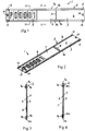
- a sign 1 according to two different embodiments of the present invention is illustrated in Figs. 1-8 .
- the sign 1 comprises an elongated base profile 2 with a bottom portion 3, a first over-folded edge portion 4a arranged along a first side edge 5a of the bottom portion 3 and a second over-folded edge portion 4b arranged along a second side edge 5b of the bottom portion opposite the first over-folded edge portion 4a.
- the bottom portion 3 has a front side 6 and a backside 7.
- a number of sign elements 8 are received in the base profile 2 and arranged on the front side 6 of the bottom portion.
- the sign elements 8 are provided with desired symbols, for instance in the form of digits or letters.
- Each sign element 8 has a first edge portion 9a (see Fig.
- the sign elements 8 suitably have the form of rectangular plates.
- the symbol of a sign element 8 is with advantage punched out of the sign element so that the bottom portion 3 of the base profile is visible through the punching.
- the sign elements 8 suitably have another colour than the bottom portion 3 so that the symbols of the sign elements 8 will appear through contrasting effect between the sign elements and the bottom portion.
- the symbol of a sign element 8 could of course also be formed in another way, for instance by printing or painting.
- a bar code label 10 (see Figs. 5, 6 and 8 ) is arranged on the front side 6 of the bottom portion between said first and second over-folded edge portions 4a, 4b and at the side of the sign elements 8.
- the bar code label 10 is suitably a sticker provided with a unique bar code pattern.
- a preferably rectangular covering plate 11 is displaceably received in the base profile 2 and arranged on the front side 6 of the bottom portion at the side of the sign elements 8.
- the covering plate 11 is fastened to the base profile 2 in the same manner as the sign elements 8 and has a first edge portion 12a (see Fig. 4 ) which is in engagement with the first over-folded edge portion 4a of the base profile and an opposite second edge portion 12b which is in engagement with the second over-folded edge portion 4b of the base profile, the over-folded edge portions 4a, 4b of the base profile overlapping said first and second edge portions 12a, 12b of the covering plate so that the covering plate 11 thereby is kept in place in the base profile 2.
- the covering plate 11 is displaceable in relation to the bottom portion 3 to an fro between a first displacement position (see Figs. 1, 2 and 7 ), in which the covering plate 11 is located on the bar code label 10 and thereby protectingly covers the bar code label, and a second displacement position (see Figs. 5, 6 and 8 ), in which the covering plate 11 is located at the side of the bar code label 10 and thereby leaves the bar code label accessible for reading.
- the covering plate 11 is displaceable in relation to the base profile 2 in the longitudinal direction of the base profile, i.e. along the over-folded edge portions 4a, 4b of the base profile.
- the covering plate 11 could be displaceable in the cross-direction of the base profile through a slit arranged in one of the over-folded edge portions 4a, 4b of the base profile.
- the covering plate 11 may be completely blank or provided with a company logo or other marking.
- a covering plate 11 and a desired combination of sign elements 8 are inserted into the base profile 2 from an end of the base profile so that the over-folded edge portions 4a, 4b of the base profile are made to overlap the first and second edge portions 12a, 12b of the covering plate and the first and second edge portions 9a, 9b of the sign elements.
- the over-folded edge portions 4a, 4b are then deformed at their ends at the areas marked with 13 by pressing the edge portions 4a, 4b inwards against the bottom portion 3 in these areas so that the covering plate 11 and the sign elements 8 are unable to slide past these areas.
- the covering plate 11 and the sign elements 8 are kept in place in the base profile 2 and prevented from sliding out of the base profile.
- Through holes 14 are arranged in the end portions of the base profile so that the sign 1 through these holes may be fixed to an object by means of fastening members in the form of for instance screws, nails or rivets.
- the base profile 2, the sign elements 8 and the covering plate 11 are suitably made of aluminium or other suitable metal.
- the covering plate 11 is provided with a handle 15 which is designed to be gripped with one or more finger or a hand by a user in order to displace the covering plate 11 in relation to the base profile 2 between the above-mentioned displacement positions.
- the sign 1 comprises a springy locking member 16 which is intended to be clamped to the base profile 2 by engagement with the first and second over-folded edge portions 4a, 4b of the base profile to thereby keep the covering plate 11 in said first displacement position.
- the locking member 16 comprises an elongated base portion 17 which extends between the over-folded edge portions 4a, 4b of the base profile, a first leg 18a which is configured for engagement with the first over-folded edge portion 4a of the base profile and an opposite second leg 18b which is configured for engagement with the second over-folded edge portion 4b of the base profile.
- the legs 18a, 18b are springingly connected to each other through the base portion 17 and are displaceable in the direction towards each other against the action of a spring force.
- the locking member 16 is displaceably received in the base profile 2 so as to be displaceable in relation to the base profile 2 in the longitudinal direction of the base profile, i.e. along the over-folded edge portions 4a, 4b of the base profile.
- each leg 18a, 18b is pressed against the over-folded edge portions 4a, 4b of the base profile so that the locking member 16 is held to the base profile 2 in the prevailing position.
- each leg is at its outer end provided with a gripping part 19a, 19b which projects from the bottom portion 3 of the base profile and which is configured to be grippable by the fingers.
- the base portion 17 and the legs 18a, 18b of the locking member are preferably formed in one piece of spring steel.
- the locking member 16 is with advantage fixed to the covering plate 11 so as to be displaceable in relation to the base profile 2 together with the covering plate.
- the above-mentioned gripping parts 19a, 19b of the legs 18a, 18b of the locking member may be used as handles in connection with a displacement of the covering plate 11 along the base profile 2.
- the base profile 2 and the covering plate 11 could be provided with recesses and projections which come into engagement with each other with snap-in effect when the covering plate 11 assumes the above-mentioned second displacement position and thereby keeps the covering plates in this displacement position so as to thereby secure that the bar code label 10 remains uncovered in connection with a reading thereof.
Landscapes
- Physics & Mathematics (AREA)
- General Physics & Mathematics (AREA)
- Engineering & Computer Science (AREA)
- Theoretical Computer Science (AREA)
- Road Signs Or Road Markings (AREA)
- Vehicle Waterproofing, Decoration, And Sanitation Devices (AREA)
Claims (6)
- Schild, aufweisend:
ein länglicher Basisprofil (2) mit einem unteren Bereich (3), einem ersten gefalzten Randbereich (4a), der entlang eines ersten Seitenrands (5a) des unteren Bereichs angeordnet ist, und einem zweiten gefalzten Randbereich (4b), der entlang eines zweiten Seitenrands (5b) des unteren Bereichs gegenüber dem ersten gefalzten Randbereich (4a) angeordnet ist, wobei der untere Bereich (3) eine Vorderseite (6) und eine Rückseite (7) aufweist;- ein oder mehrere Schildelemente (8), das bzw. die im Basisprofil (2) aufgenommen und auf der Vorderseite (6) des unteren Bereichs angeordnet ist bzw. sind, wobei jedes dieser Schildelemente (8) einen ersten Randbereich (9a), der mit dem ersten gefalzten Randbereich (4a) des Basisprofils in Eingriff steht, und einen entgegengesetzten zweiten Randbereich (9b) aufweist, der in Eingriff mit dem zweiten gefalzten Randbereich (4b) des Basisprofils steht; und- eine Abdeckplatte (11), die verschiebbar in dem Basisprofil (2) aufgenommen und auf der Vorderseite (6) des unteren Bereichs seitlich der Schildelemente (8) angeordnet ist, wobei diese Abdeckplatte (11) einen ersten Randbereich (12a), der in Eingriff mit dem ersten gefalzten Randbereich (4a) des Basisprofils steht, und einen entgegengesetzten zweiten Randteilbereich (12b) aufweist, der in Eingriff mit dem zweiten gefalzten Randbereich (4b) des Basisprofils steht,dadurch gekennzeichnet:- dass ein Strichcode-Etikett (10) auf der Vorderseite (6) des unteren Bereichs zwischen dem ersten und dem zweiten gefalzten Randbereich (4a, 4b) und seitlich der Schildelemente (8) angeordnet ist;- dass die Abdeckplatte (11) in Bezug auf den unteren Bereich (3) hin und her verschiebbar zwischen einer ersten Verschiebungsposition ist, in der sich die Abdeckplatte (11) auf dem Strichcode-Etikett (10) befindet und dadurch das Strichcode-Etikett schützend abdeckt, und einer zweiten Verschiebungsposition, in der sich die Abdeckplatte (11) seitlich des Strichcode-Etiketts (10) befindet und dadurch das Strichcode-Etikett (10) zum Ablesen zugänglich belässt; und- dass das Schild (1) ein federnd arretierendes Element (16) aufweist, das dazu vorgesehen ist, durch einen Eingriff mit dem ersten und dem zweiten gefalzten Randbereich (4a, 4b) des Basisprofils am Basisprofil (2) festgeklemmt zu werden, um dadurch die Abdeckplatte (11) in der ersten Verschiebungsposition zu halten. - Schild nach Anspruch 1, dadurch gekennzeichnet, dass die Abdeckplatte (11) in Bezug auf das Basisprofil (2) in der Längsrichtung des Basisprofils verschiebbar ist.
- Schild nach Anspruch 1 oder 2, dadurch gekennzeichnet, dass das arretierende Element (16) einen ersten Schenkel (18a), der zum Eingriff mit dem ersten gefalzten Randbereich (4a) des Basisprofils ausgelegt ist, und einen entgegengesetzten zweiten Schenkel (18b) aufweist, der zum Eingriff mit dem zweiten gefalzten Randbereich (4b) des Basisprofils ausgelegt ist, wobei diese Schenkel (18a, 18b) federnd miteinander verbunden und in der Richtung aufeinander zu gegen die Wirkung einer Federkraft verschiebbar sind.
- Schild nach einem der Ansprüche 1 bis 3, dadurch gekennzeichnet, dass das arretierende Element (16) verschiebbar in dem Basisprofil (2) aufnehmbar ist, um in Bezug auf das Basisprofil (2) in der Längsrichtung des Basisprofils verschiebbar zu sein.
- Schild nach Anspruch 4, dadurch gekennzeichnet, dass das arretierende Element (16) an der Abdeckplatte (11) befestigt ist, um in Bezug auf das Basisprofil (2) zusammen mit der Abdeckplatte verschiebbar zu sein.
- Schild nach einem der Ansprüche 1 bis 5, dadurch gekennzeichnet, dass die Abdeckplatte (11) mit einem Handgriff (15) versehen ist, der dazu ausgelegt ist, von einem Benutzer zur Verschiebung der Abdeckplatte in Bezug auf das Basisprofil (2) ergriffen zu werden.
Applications Claiming Priority (2)
| Application Number | Priority Date | Filing Date | Title |
|---|---|---|---|
| SE1350194A SE536882C2 (sv) | 2013-02-18 | 2013-02-18 | Skylt innefattande teckenelement |
| PCT/SE2014/050173 WO2014126530A1 (en) | 2013-02-18 | 2014-02-13 | Sign with sign elements |
Publications (3)
| Publication Number | Publication Date |
|---|---|
| EP2956922A1 EP2956922A1 (de) | 2015-12-23 |
| EP2956922A4 EP2956922A4 (de) | 2016-11-16 |
| EP2956922B1 true EP2956922B1 (de) | 2018-06-20 |
Family
ID=51354419
Family Applications (1)
| Application Number | Title | Priority Date | Filing Date |
|---|---|---|---|
| EP14751558.9A Active EP2956922B1 (de) | 2013-02-18 | 2014-02-13 | Schild mit zeichenelemente |
Country Status (5)
| Country | Link |
|---|---|
| EP (1) | EP2956922B1 (de) |
| DK (1) | DK2956922T3 (de) |
| ES (1) | ES2687896T3 (de) |
| SE (1) | SE536882C2 (de) |
| WO (1) | WO2014126530A1 (de) |
Families Citing this family (1)
| Publication number | Priority date | Publication date | Assignee | Title |
|---|---|---|---|---|
| EP4345800A1 (de) * | 2022-09-30 | 2024-04-03 | Friedr. Lohmann GmbH Werk für Spezial- & Edelsähle | Markierungseinheit |
Family Cites Families (9)
| Publication number | Priority date | Publication date | Assignee | Title |
|---|---|---|---|---|
| GB191503078A (en) * | 1915-02-25 | 1915-12-16 | Smith Nehemiah Lord | Improvements in or connected with Notice Boards or Indicators. |
| GB376507A (en) * | 1931-07-21 | 1932-07-14 | John Humphrey Herbert Goodall | Improvements in or relating to signs |
| GB506243A (en) * | 1938-08-22 | 1939-05-24 | David Gerard Wassell | Improvements in or relating to registration number plates for vehicles |
| US3913249A (en) * | 1974-08-22 | 1975-10-21 | Walter Kaslow | Brand name shopping guide |
| SE420938B (sv) * | 1981-03-12 | 1981-11-09 | Linexa Maskin Ab | Anordning vid snoplogar, serskilt plogar avsedda att passera hinder |
| SE468379B (sv) | 1991-05-13 | 1993-01-11 | Hammarprodukter Ab | Verktyg |
| SE504702C2 (sv) | 1995-04-19 | 1997-04-07 | Lars Hammar | Verktyg |
| WO2000033284A1 (en) * | 1998-12-02 | 2000-06-08 | John Dimitrov Proynoff | Information panel guide |
| US20070266604A1 (en) * | 2006-04-27 | 2007-11-22 | Garfinkle Benjamin L | Decorative and informative signage |
-
2013
- 2013-02-18 SE SE1350194A patent/SE536882C2/sv unknown
-
2014
- 2014-02-13 DK DK14751558.9T patent/DK2956922T3/en active
- 2014-02-13 WO PCT/SE2014/050173 patent/WO2014126530A1/en not_active Ceased
- 2014-02-13 EP EP14751558.9A patent/EP2956922B1/de active Active
- 2014-02-13 ES ES14751558.9T patent/ES2687896T3/es active Active
Non-Patent Citations (1)
| Title |
|---|
| None * |
Also Published As
| Publication number | Publication date |
|---|---|
| SE536882C2 (sv) | 2014-10-14 |
| WO2014126530A1 (en) | 2014-08-21 |
| SE1350194A1 (sv) | 2014-08-19 |
| EP2956922A1 (de) | 2015-12-23 |
| EP2956922A4 (de) | 2016-11-16 |
| ES2687896T3 (es) | 2018-10-29 |
| DK2956922T3 (en) | 2018-10-08 |
Similar Documents
| Publication | Publication Date | Title |
|---|---|---|
| EP0069100B1 (de) | Markiergerät für elektrische Leitungen, Kabel, Rohre oder dergleichen und Verfahren zu dessen Herstellung | |
| US9490743B2 (en) | Grounding clips and tabs for mounting components to solar modules | |
| EP2956922B1 (de) | Schild mit zeichenelemente | |
| US4033057A (en) | Marking tapes for marking articles | |
| DE50300419D1 (de) | Sensor-Spiegel-Anordnung an einer Windschutzscheibe | |
| EP2383852B1 (de) | Elektrisches Installationsgerät | |
| CA2330940A1 (en) | Rectangular panel fastener | |
| JP2018507139A (ja) | ライセンスプレートを保持するためのプレートホルダ | |
| TR199900221A3 (tr) | Firinlandiginda kizil-kahve bir renk alan boyar cisimler, bunlarin hazirlanmasi için islem ve kullanimlari. | |
| US1865485A (en) | Means to protect corners of frangible material | |
| US20020092219A1 (en) | Vandal resistant sign and method | |
| CN203715049U (zh) | 一种自动扶梯踏板 | |
| US20250018550A1 (en) | Hand-held tool and functional part for a detent connection with a grip region of a hand-held tool | |
| DE3219510A1 (de) | Elektrisches installationsgeraet | |
| GB1578676A (en) | Identification carrier | |
| WO2006029703A3 (de) | Aufhänger zum asfhängen von gegenständen an ebenen flächen sowie anordnung zum aufhängen von gegenständen | |
| DE60106833D1 (de) | Schutzverpackung für einen zylindrischen Gegenstand mit einer Befestigungsvorrichtung | |
| EP3335940B1 (de) | Halterung zum verankern eines dokuments an einem fahrzeug | |
| EP0849757A3 (de) | Gehäuse für ein elektrisches Installationsgerät, insbesondere für einen Leitungsschutzschalter oder Fehlerstromschutzschalter oder dergleichen | |
| DE7327094U (de) | Elektrischer Installationsschalter | |
| DE69900011D1 (de) | Auf drei Seiten geschlossener Ordner, mit einer versetzten Oeffnung | |
| DE1077050B (de) | Bezeichnungsschild z. B. fuer elektrische Anlagen | |
| KR200336149Y1 (ko) | 문패 | |
| FR2829198B1 (fr) | Pince a double blocage sur un axe | |
| DE202007004382U1 (de) | Mehrzweckschlüsselanhänger |
Legal Events
| Date | Code | Title | Description |
|---|---|---|---|
| PUAI | Public reference made under article 153(3) epc to a published international application that has entered the european phase |
Free format text: ORIGINAL CODE: 0009012 |
|
| 17P | Request for examination filed |
Effective date: 20150720 |
|
| AK | Designated contracting states |
Kind code of ref document: A1 Designated state(s): AL AT BE BG CH CY CZ DE DK EE ES FI FR GB GR HR HU IE IS IT LI LT LU LV MC MK MT NL NO PL PT RO RS SE SI SK SM TR |
|
| AX | Request for extension of the european patent |
Extension state: BA ME |
|
| DAX | Request for extension of the european patent (deleted) | ||
| A4 | Supplementary search report drawn up and despatched |
Effective date: 20161019 |
|
| RIC1 | Information provided on ipc code assigned before grant |
Ipc: G09F 7/10 20060101AFI20161013BHEP Ipc: G09F 7/00 20060101ALI20161013BHEP Ipc: G09F 3/00 20060101ALI20161013BHEP |
|
| GRAP | Despatch of communication of intention to grant a patent |
Free format text: ORIGINAL CODE: EPIDOSNIGR1 |
|
| STAA | Information on the status of an ep patent application or granted ep patent |
Free format text: STATUS: GRANT OF PATENT IS INTENDED |
|
| INTG | Intention to grant announced |
Effective date: 20180111 |
|
| GRAS | Grant fee paid |
Free format text: ORIGINAL CODE: EPIDOSNIGR3 |
|
| GRAA | (expected) grant |
Free format text: ORIGINAL CODE: 0009210 |
|
| STAA | Information on the status of an ep patent application or granted ep patent |
Free format text: STATUS: THE PATENT HAS BEEN GRANTED |
|
| AK | Designated contracting states |
Kind code of ref document: B1 Designated state(s): AL AT BE BG CH CY CZ DE DK EE ES FI FR GB GR HR HU IE IS IT LI LT LU LV MC MK MT NL NO PL PT RO RS SE SI SK SM TR |
|
| REG | Reference to a national code |
Ref country code: GB Ref legal event code: FG4D |
|
| REG | Reference to a national code |
Ref country code: IE Ref legal event code: FG4D |
|
| REG | Reference to a national code |
Ref country code: AT Ref legal event code: REF Ref document number: 1011141 Country of ref document: AT Kind code of ref document: T Effective date: 20180715 |
|
| REG | Reference to a national code |
Ref country code: DE Ref legal event code: R096 Ref document number: 602014027310 Country of ref document: DE |
|
| REG | Reference to a national code |
Ref country code: DK Ref legal event code: T3 Effective date: 20181001 |
|
| REG | Reference to a national code |
Ref country code: NL Ref legal event code: MP Effective date: 20180620 |
|
| REG | Reference to a national code |
Ref country code: ES Ref legal event code: FG2A Ref document number: 2687896 Country of ref document: ES Kind code of ref document: T3 Effective date: 20181029 Ref country code: NO Ref legal event code: T2 Effective date: 20180620 |
|
| PG25 | Lapsed in a contracting state [announced via postgrant information from national office to epo] |
Ref country code: FI Free format text: LAPSE BECAUSE OF FAILURE TO SUBMIT A TRANSLATION OF THE DESCRIPTION OR TO PAY THE FEE WITHIN THE PRESCRIBED TIME-LIMIT Effective date: 20180620 Ref country code: BG Free format text: LAPSE BECAUSE OF FAILURE TO SUBMIT A TRANSLATION OF THE DESCRIPTION OR TO PAY THE FEE WITHIN THE PRESCRIBED TIME-LIMIT Effective date: 20180920 Ref country code: SE Free format text: LAPSE BECAUSE OF FAILURE TO SUBMIT A TRANSLATION OF THE DESCRIPTION OR TO PAY THE FEE WITHIN THE PRESCRIBED TIME-LIMIT Effective date: 20180620 Ref country code: LT Free format text: LAPSE BECAUSE OF FAILURE TO SUBMIT A TRANSLATION OF THE DESCRIPTION OR TO PAY THE FEE WITHIN THE PRESCRIBED TIME-LIMIT Effective date: 20180620 |
|
| REG | Reference to a national code |
Ref country code: LT Ref legal event code: MG4D |
|
| REG | Reference to a national code |
Ref country code: EE Ref legal event code: FG4A Ref document number: E016113 Country of ref document: EE Effective date: 20180913 |
|
| PG25 | Lapsed in a contracting state [announced via postgrant information from national office to epo] |
Ref country code: HR Free format text: LAPSE BECAUSE OF FAILURE TO SUBMIT A TRANSLATION OF THE DESCRIPTION OR TO PAY THE FEE WITHIN THE PRESCRIBED TIME-LIMIT Effective date: 20180620 Ref country code: RS Free format text: LAPSE BECAUSE OF FAILURE TO SUBMIT A TRANSLATION OF THE DESCRIPTION OR TO PAY THE FEE WITHIN THE PRESCRIBED TIME-LIMIT Effective date: 20180620 Ref country code: GR Free format text: LAPSE BECAUSE OF FAILURE TO SUBMIT A TRANSLATION OF THE DESCRIPTION OR TO PAY THE FEE WITHIN THE PRESCRIBED TIME-LIMIT Effective date: 20180921 |
|
| PG25 | Lapsed in a contracting state [announced via postgrant information from national office to epo] |
Ref country code: NL Free format text: LAPSE BECAUSE OF FAILURE TO SUBMIT A TRANSLATION OF THE DESCRIPTION OR TO PAY THE FEE WITHIN THE PRESCRIBED TIME-LIMIT Effective date: 20180620 |
|
| PG25 | Lapsed in a contracting state [announced via postgrant information from national office to epo] |
Ref country code: PL Free format text: LAPSE BECAUSE OF FAILURE TO SUBMIT A TRANSLATION OF THE DESCRIPTION OR TO PAY THE FEE WITHIN THE PRESCRIBED TIME-LIMIT Effective date: 20180620 Ref country code: CZ Free format text: LAPSE BECAUSE OF FAILURE TO SUBMIT A TRANSLATION OF THE DESCRIPTION OR TO PAY THE FEE WITHIN THE PRESCRIBED TIME-LIMIT Effective date: 20180620 Ref country code: IS Free format text: LAPSE BECAUSE OF FAILURE TO SUBMIT A TRANSLATION OF THE DESCRIPTION OR TO PAY THE FEE WITHIN THE PRESCRIBED TIME-LIMIT Effective date: 20181020 Ref country code: RO Free format text: LAPSE BECAUSE OF FAILURE TO SUBMIT A TRANSLATION OF THE DESCRIPTION OR TO PAY THE FEE WITHIN THE PRESCRIBED TIME-LIMIT Effective date: 20180620 Ref country code: SK Free format text: LAPSE BECAUSE OF FAILURE TO SUBMIT A TRANSLATION OF THE DESCRIPTION OR TO PAY THE FEE WITHIN THE PRESCRIBED TIME-LIMIT Effective date: 20180620 |
|
| PG25 | Lapsed in a contracting state [announced via postgrant information from national office to epo] |
Ref country code: IT Free format text: LAPSE BECAUSE OF FAILURE TO SUBMIT A TRANSLATION OF THE DESCRIPTION OR TO PAY THE FEE WITHIN THE PRESCRIBED TIME-LIMIT Effective date: 20180620 Ref country code: SM Free format text: LAPSE BECAUSE OF FAILURE TO SUBMIT A TRANSLATION OF THE DESCRIPTION OR TO PAY THE FEE WITHIN THE PRESCRIBED TIME-LIMIT Effective date: 20180620 |
|
| REG | Reference to a national code |
Ref country code: DE Ref legal event code: R097 Ref document number: 602014027310 Country of ref document: DE |
|
| PLBE | No opposition filed within time limit |
Free format text: ORIGINAL CODE: 0009261 |
|
| STAA | Information on the status of an ep patent application or granted ep patent |
Free format text: STATUS: NO OPPOSITION FILED WITHIN TIME LIMIT |
|
| 26N | No opposition filed |
Effective date: 20190321 |
|
| PG25 | Lapsed in a contracting state [announced via postgrant information from national office to epo] |
Ref country code: SI Free format text: LAPSE BECAUSE OF FAILURE TO SUBMIT A TRANSLATION OF THE DESCRIPTION OR TO PAY THE FEE WITHIN THE PRESCRIBED TIME-LIMIT Effective date: 20180620 |
|
| REG | Reference to a national code |
Ref country code: CH Ref legal event code: PL |
|
| PG25 | Lapsed in a contracting state [announced via postgrant information from national office to epo] |
Ref country code: MC Free format text: LAPSE BECAUSE OF FAILURE TO SUBMIT A TRANSLATION OF THE DESCRIPTION OR TO PAY THE FEE WITHIN THE PRESCRIBED TIME-LIMIT Effective date: 20180620 Ref country code: LU Free format text: LAPSE BECAUSE OF NON-PAYMENT OF DUE FEES Effective date: 20190213 |
|
| REG | Reference to a national code |
Ref country code: BE Ref legal event code: MM Effective date: 20190228 |
|
| REG | Reference to a national code |
Ref country code: IE Ref legal event code: MM4A |
|
| PG25 | Lapsed in a contracting state [announced via postgrant information from national office to epo] |
Ref country code: AL Free format text: LAPSE BECAUSE OF FAILURE TO SUBMIT A TRANSLATION OF THE DESCRIPTION OR TO PAY THE FEE WITHIN THE PRESCRIBED TIME-LIMIT Effective date: 20180620 |
|
| PG25 | Lapsed in a contracting state [announced via postgrant information from national office to epo] |
Ref country code: LI Free format text: LAPSE BECAUSE OF NON-PAYMENT OF DUE FEES Effective date: 20190228 Ref country code: CH Free format text: LAPSE BECAUSE OF NON-PAYMENT OF DUE FEES Effective date: 20190228 |
|
| PG25 | Lapsed in a contracting state [announced via postgrant information from national office to epo] |
Ref country code: IE Free format text: LAPSE BECAUSE OF NON-PAYMENT OF DUE FEES Effective date: 20190213 |
|
| PG25 | Lapsed in a contracting state [announced via postgrant information from national office to epo] |
Ref country code: BE Free format text: LAPSE BECAUSE OF NON-PAYMENT OF DUE FEES Effective date: 20190228 |
|
| PG25 | Lapsed in a contracting state [announced via postgrant information from national office to epo] |
Ref country code: PT Free format text: LAPSE BECAUSE OF FAILURE TO SUBMIT A TRANSLATION OF THE DESCRIPTION OR TO PAY THE FEE WITHIN THE PRESCRIBED TIME-LIMIT Effective date: 20181022 Ref country code: MT Free format text: LAPSE BECAUSE OF NON-PAYMENT OF DUE FEES Effective date: 20190213 |
|
| REG | Reference to a national code |
Ref country code: AT Ref legal event code: UEP Ref document number: 1011141 Country of ref document: AT Kind code of ref document: T Effective date: 20180620 |
|
| PG25 | Lapsed in a contracting state [announced via postgrant information from national office to epo] |
Ref country code: CY Free format text: LAPSE BECAUSE OF FAILURE TO SUBMIT A TRANSLATION OF THE DESCRIPTION OR TO PAY THE FEE WITHIN THE PRESCRIBED TIME-LIMIT Effective date: 20180620 |
|
| PG25 | Lapsed in a contracting state [announced via postgrant information from national office to epo] |
Ref country code: HU Free format text: LAPSE BECAUSE OF FAILURE TO SUBMIT A TRANSLATION OF THE DESCRIPTION OR TO PAY THE FEE WITHIN THE PRESCRIBED TIME-LIMIT; INVALID AB INITIO Effective date: 20140213 |
|
| PG25 | Lapsed in a contracting state [announced via postgrant information from national office to epo] |
Ref country code: MK Free format text: LAPSE BECAUSE OF FAILURE TO SUBMIT A TRANSLATION OF THE DESCRIPTION OR TO PAY THE FEE WITHIN THE PRESCRIBED TIME-LIMIT Effective date: 20180620 |
|
| P01 | Opt-out of the competence of the unified patent court (upc) registered |
Effective date: 20230520 |
|
| PGFP | Annual fee paid to national office [announced via postgrant information from national office to epo] |
Ref country code: LV Payment date: 20250219 Year of fee payment: 12 Ref country code: EE Payment date: 20250226 Year of fee payment: 12 |
|
| PGFP | Annual fee paid to national office [announced via postgrant information from national office to epo] |
Ref country code: GB Payment date: 20260217 Year of fee payment: 13 |
|
| PGFP | Annual fee paid to national office [announced via postgrant information from national office to epo] |
Ref country code: ES Payment date: 20260303 Year of fee payment: 13 |
|
| PGFP | Annual fee paid to national office [announced via postgrant information from national office to epo] |
Ref country code: NO Payment date: 20260219 Year of fee payment: 13 Ref country code: DE Payment date: 20260217 Year of fee payment: 13 Ref country code: DK Payment date: 20260220 Year of fee payment: 13 |
|
| PGFP | Annual fee paid to national office [announced via postgrant information from national office to epo] |
Ref country code: AT Payment date: 20260217 Year of fee payment: 13 |
|
| PGFP | Annual fee paid to national office [announced via postgrant information from national office to epo] |
Ref country code: FR Payment date: 20260217 Year of fee payment: 13 |
|
| PGFP | Annual fee paid to national office [announced via postgrant information from national office to epo] |
Ref country code: TR Payment date: 20260126 Year of fee payment: 13 |