EP2955427A1 - Station de remplissage de réservoirs de gaz sous pression - Google Patents
Station de remplissage de réservoirs de gaz sous pression Download PDFInfo
- Publication number
- EP2955427A1 EP2955427A1 EP15159230.0A EP15159230A EP2955427A1 EP 2955427 A1 EP2955427 A1 EP 2955427A1 EP 15159230 A EP15159230 A EP 15159230A EP 2955427 A1 EP2955427 A1 EP 2955427A1
- Authority
- EP
- European Patent Office
- Prior art keywords
- heat exchanger
- support
- terminal
- distribution
- station
- Prior art date
- Legal status (The legal status is an assumption and is not a legal conclusion. Google has not performed a legal analysis and makes no representation as to the accuracy of the status listed.)
- Granted
Links
Images

Classifications
-
- F—MECHANICAL ENGINEERING; LIGHTING; HEATING; WEAPONS; BLASTING
- F17—STORING OR DISTRIBUTING GASES OR LIQUIDS
- F17C—VESSELS FOR CONTAINING OR STORING COMPRESSED, LIQUEFIED OR SOLIDIFIED GASES; FIXED-CAPACITY GAS-HOLDERS; FILLING VESSELS WITH, OR DISCHARGING FROM VESSELS, COMPRESSED, LIQUEFIED, OR SOLIDIFIED GASES
- F17C5/00—Methods or apparatus for filling containers with liquefied, solidified, or compressed gases under pressures
- F17C5/002—Automated filling apparatus
- F17C5/007—Automated filling apparatus for individual gas tanks or containers, e.g. in vehicles
-
- F—MECHANICAL ENGINEERING; LIGHTING; HEATING; WEAPONS; BLASTING
- F17—STORING OR DISTRIBUTING GASES OR LIQUIDS
- F17C—VESSELS FOR CONTAINING OR STORING COMPRESSED, LIQUEFIED OR SOLIDIFIED GASES; FIXED-CAPACITY GAS-HOLDERS; FILLING VESSELS WITH, OR DISCHARGING FROM VESSELS, COMPRESSED, LIQUEFIED, OR SOLIDIFIED GASES
- F17C13/00—Details of vessels or of the filling or discharging of vessels
- F17C13/02—Special adaptations of indicating, measuring, or monitoring equipment
-
- F—MECHANICAL ENGINEERING; LIGHTING; HEATING; WEAPONS; BLASTING
- F17—STORING OR DISTRIBUTING GASES OR LIQUIDS
- F17C—VESSELS FOR CONTAINING OR STORING COMPRESSED, LIQUEFIED OR SOLIDIFIED GASES; FIXED-CAPACITY GAS-HOLDERS; FILLING VESSELS WITH, OR DISCHARGING FROM VESSELS, COMPRESSED, LIQUEFIED, OR SOLIDIFIED GASES
- F17C13/00—Details of vessels or of the filling or discharging of vessels
- F17C13/02—Special adaptations of indicating, measuring, or monitoring equipment
- F17C13/025—Special adaptations of indicating, measuring, or monitoring equipment having the pressure as the parameter
-
- F—MECHANICAL ENGINEERING; LIGHTING; HEATING; WEAPONS; BLASTING
- F17—STORING OR DISTRIBUTING GASES OR LIQUIDS
- F17C—VESSELS FOR CONTAINING OR STORING COMPRESSED, LIQUEFIED OR SOLIDIFIED GASES; FIXED-CAPACITY GAS-HOLDERS; FILLING VESSELS WITH, OR DISCHARGING FROM VESSELS, COMPRESSED, LIQUEFIED, OR SOLIDIFIED GASES
- F17C5/00—Methods or apparatus for filling containers with liquefied, solidified, or compressed gases under pressures
- F17C5/06—Methods or apparatus for filling containers with liquefied, solidified, or compressed gases under pressures for filling with compressed gases
-
- F—MECHANICAL ENGINEERING; LIGHTING; HEATING; WEAPONS; BLASTING
- F17—STORING OR DISTRIBUTING GASES OR LIQUIDS
- F17C—VESSELS FOR CONTAINING OR STORING COMPRESSED, LIQUEFIED OR SOLIDIFIED GASES; FIXED-CAPACITY GAS-HOLDERS; FILLING VESSELS WITH, OR DISCHARGING FROM VESSELS, COMPRESSED, LIQUEFIED, OR SOLIDIFIED GASES
- F17C2205/00—Vessel construction, in particular mounting arrangements, attachments or identifications means
- F17C2205/01—Mounting arrangements
- F17C2205/0103—Exterior arrangements
- F17C2205/0107—Frames
-
- F—MECHANICAL ENGINEERING; LIGHTING; HEATING; WEAPONS; BLASTING
- F17—STORING OR DISTRIBUTING GASES OR LIQUIDS
- F17C—VESSELS FOR CONTAINING OR STORING COMPRESSED, LIQUEFIED OR SOLIDIFIED GASES; FIXED-CAPACITY GAS-HOLDERS; FILLING VESSELS WITH, OR DISCHARGING FROM VESSELS, COMPRESSED, LIQUEFIED, OR SOLIDIFIED GASES
- F17C2205/00—Vessel construction, in particular mounting arrangements, attachments or identifications means
- F17C2205/01—Mounting arrangements
- F17C2205/0153—Details of mounting arrangements
- F17C2205/018—Supporting feet
-
- F—MECHANICAL ENGINEERING; LIGHTING; HEATING; WEAPONS; BLASTING
- F17—STORING OR DISTRIBUTING GASES OR LIQUIDS
- F17C—VESSELS FOR CONTAINING OR STORING COMPRESSED, LIQUEFIED OR SOLIDIFIED GASES; FIXED-CAPACITY GAS-HOLDERS; FILLING VESSELS WITH, OR DISCHARGING FROM VESSELS, COMPRESSED, LIQUEFIED, OR SOLIDIFIED GASES
- F17C2205/00—Vessel construction, in particular mounting arrangements, attachments or identifications means
- F17C2205/03—Fluid connections, filters, valves, closure means or other attachments
- F17C2205/0302—Fittings, valves, filters, or components in connection with the gas storage device
- F17C2205/0352—Pipes
- F17C2205/0364—Pipes flexible or articulated, e.g. a hose
-
- F—MECHANICAL ENGINEERING; LIGHTING; HEATING; WEAPONS; BLASTING
- F17—STORING OR DISTRIBUTING GASES OR LIQUIDS
- F17C—VESSELS FOR CONTAINING OR STORING COMPRESSED, LIQUEFIED OR SOLIDIFIED GASES; FIXED-CAPACITY GAS-HOLDERS; FILLING VESSELS WITH, OR DISCHARGING FROM VESSELS, COMPRESSED, LIQUEFIED, OR SOLIDIFIED GASES
- F17C2205/00—Vessel construction, in particular mounting arrangements, attachments or identifications means
- F17C2205/03—Fluid connections, filters, valves, closure means or other attachments
- F17C2205/0302—Fittings, valves, filters, or components in connection with the gas storage device
- F17C2205/037—Quick connecting means, e.g. couplings
-
- F—MECHANICAL ENGINEERING; LIGHTING; HEATING; WEAPONS; BLASTING
- F17—STORING OR DISTRIBUTING GASES OR LIQUIDS
- F17C—VESSELS FOR CONTAINING OR STORING COMPRESSED, LIQUEFIED OR SOLIDIFIED GASES; FIXED-CAPACITY GAS-HOLDERS; FILLING VESSELS WITH, OR DISCHARGING FROM VESSELS, COMPRESSED, LIQUEFIED, OR SOLIDIFIED GASES
- F17C2205/00—Vessel construction, in particular mounting arrangements, attachments or identifications means
- F17C2205/03—Fluid connections, filters, valves, closure means or other attachments
- F17C2205/0302—Fittings, valves, filters, or components in connection with the gas storage device
- F17C2205/0379—Manholes or access openings for human beings
-
- F—MECHANICAL ENGINEERING; LIGHTING; HEATING; WEAPONS; BLASTING
- F17—STORING OR DISTRIBUTING GASES OR LIQUIDS
- F17C—VESSELS FOR CONTAINING OR STORING COMPRESSED, LIQUEFIED OR SOLIDIFIED GASES; FIXED-CAPACITY GAS-HOLDERS; FILLING VESSELS WITH, OR DISCHARGING FROM VESSELS, COMPRESSED, LIQUEFIED, OR SOLIDIFIED GASES
- F17C2221/00—Handled fluid, in particular type of fluid
- F17C2221/01—Pure fluids
- F17C2221/012—Hydrogen
-
- F—MECHANICAL ENGINEERING; LIGHTING; HEATING; WEAPONS; BLASTING
- F17—STORING OR DISTRIBUTING GASES OR LIQUIDS
- F17C—VESSELS FOR CONTAINING OR STORING COMPRESSED, LIQUEFIED OR SOLIDIFIED GASES; FIXED-CAPACITY GAS-HOLDERS; FILLING VESSELS WITH, OR DISCHARGING FROM VESSELS, COMPRESSED, LIQUEFIED, OR SOLIDIFIED GASES
- F17C2223/00—Handled fluid before transfer, i.e. state of fluid when stored in the vessel or before transfer from the vessel
- F17C2223/01—Handled fluid before transfer, i.e. state of fluid when stored in the vessel or before transfer from the vessel characterised by the phase
- F17C2223/0107—Single phase
- F17C2223/0123—Single phase gaseous, e.g. CNG, GNC
-
- F—MECHANICAL ENGINEERING; LIGHTING; HEATING; WEAPONS; BLASTING
- F17—STORING OR DISTRIBUTING GASES OR LIQUIDS
- F17C—VESSELS FOR CONTAINING OR STORING COMPRESSED, LIQUEFIED OR SOLIDIFIED GASES; FIXED-CAPACITY GAS-HOLDERS; FILLING VESSELS WITH, OR DISCHARGING FROM VESSELS, COMPRESSED, LIQUEFIED, OR SOLIDIFIED GASES
- F17C2223/00—Handled fluid before transfer, i.e. state of fluid when stored in the vessel or before transfer from the vessel
- F17C2223/01—Handled fluid before transfer, i.e. state of fluid when stored in the vessel or before transfer from the vessel characterised by the phase
- F17C2223/0146—Two-phase
- F17C2223/0153—Liquefied gas, e.g. LPG, GPL
- F17C2223/0161—Liquefied gas, e.g. LPG, GPL cryogenic, e.g. LNG, GNL, PLNG
-
- F—MECHANICAL ENGINEERING; LIGHTING; HEATING; WEAPONS; BLASTING
- F17—STORING OR DISTRIBUTING GASES OR LIQUIDS
- F17C—VESSELS FOR CONTAINING OR STORING COMPRESSED, LIQUEFIED OR SOLIDIFIED GASES; FIXED-CAPACITY GAS-HOLDERS; FILLING VESSELS WITH, OR DISCHARGING FROM VESSELS, COMPRESSED, LIQUEFIED, OR SOLIDIFIED GASES
- F17C2223/00—Handled fluid before transfer, i.e. state of fluid when stored in the vessel or before transfer from the vessel
- F17C2223/03—Handled fluid before transfer, i.e. state of fluid when stored in the vessel or before transfer from the vessel characterised by the pressure level
- F17C2223/033—Small pressure, e.g. for liquefied gas
-
- F—MECHANICAL ENGINEERING; LIGHTING; HEATING; WEAPONS; BLASTING
- F17—STORING OR DISTRIBUTING GASES OR LIQUIDS
- F17C—VESSELS FOR CONTAINING OR STORING COMPRESSED, LIQUEFIED OR SOLIDIFIED GASES; FIXED-CAPACITY GAS-HOLDERS; FILLING VESSELS WITH, OR DISCHARGING FROM VESSELS, COMPRESSED, LIQUEFIED, OR SOLIDIFIED GASES
- F17C2223/00—Handled fluid before transfer, i.e. state of fluid when stored in the vessel or before transfer from the vessel
- F17C2223/03—Handled fluid before transfer, i.e. state of fluid when stored in the vessel or before transfer from the vessel characterised by the pressure level
- F17C2223/035—High pressure (>10 bar)
-
- F—MECHANICAL ENGINEERING; LIGHTING; HEATING; WEAPONS; BLASTING
- F17—STORING OR DISTRIBUTING GASES OR LIQUIDS
- F17C—VESSELS FOR CONTAINING OR STORING COMPRESSED, LIQUEFIED OR SOLIDIFIED GASES; FIXED-CAPACITY GAS-HOLDERS; FILLING VESSELS WITH, OR DISCHARGING FROM VESSELS, COMPRESSED, LIQUEFIED, OR SOLIDIFIED GASES
- F17C2223/00—Handled fluid before transfer, i.e. state of fluid when stored in the vessel or before transfer from the vessel
- F17C2223/03—Handled fluid before transfer, i.e. state of fluid when stored in the vessel or before transfer from the vessel characterised by the pressure level
- F17C2223/036—Very high pressure (>80 bar)
-
- F—MECHANICAL ENGINEERING; LIGHTING; HEATING; WEAPONS; BLASTING
- F17—STORING OR DISTRIBUTING GASES OR LIQUIDS
- F17C—VESSELS FOR CONTAINING OR STORING COMPRESSED, LIQUEFIED OR SOLIDIFIED GASES; FIXED-CAPACITY GAS-HOLDERS; FILLING VESSELS WITH, OR DISCHARGING FROM VESSELS, COMPRESSED, LIQUEFIED, OR SOLIDIFIED GASES
- F17C2223/00—Handled fluid before transfer, i.e. state of fluid when stored in the vessel or before transfer from the vessel
- F17C2223/04—Handled fluid before transfer, i.e. state of fluid when stored in the vessel or before transfer from the vessel characterised by other properties of handled fluid before transfer
- F17C2223/042—Localisation of the removal point
- F17C2223/043—Localisation of the removal point in the gas
-
- F—MECHANICAL ENGINEERING; LIGHTING; HEATING; WEAPONS; BLASTING
- F17—STORING OR DISTRIBUTING GASES OR LIQUIDS
- F17C—VESSELS FOR CONTAINING OR STORING COMPRESSED, LIQUEFIED OR SOLIDIFIED GASES; FIXED-CAPACITY GAS-HOLDERS; FILLING VESSELS WITH, OR DISCHARGING FROM VESSELS, COMPRESSED, LIQUEFIED, OR SOLIDIFIED GASES
- F17C2223/00—Handled fluid before transfer, i.e. state of fluid when stored in the vessel or before transfer from the vessel
- F17C2223/04—Handled fluid before transfer, i.e. state of fluid when stored in the vessel or before transfer from the vessel characterised by other properties of handled fluid before transfer
- F17C2223/042—Localisation of the removal point
- F17C2223/046—Localisation of the removal point in the liquid
-
- F—MECHANICAL ENGINEERING; LIGHTING; HEATING; WEAPONS; BLASTING
- F17—STORING OR DISTRIBUTING GASES OR LIQUIDS
- F17C—VESSELS FOR CONTAINING OR STORING COMPRESSED, LIQUEFIED OR SOLIDIFIED GASES; FIXED-CAPACITY GAS-HOLDERS; FILLING VESSELS WITH, OR DISCHARGING FROM VESSELS, COMPRESSED, LIQUEFIED, OR SOLIDIFIED GASES
- F17C2225/00—Handled fluid after transfer, i.e. state of fluid after transfer from the vessel
- F17C2225/01—Handled fluid after transfer, i.e. state of fluid after transfer from the vessel characterised by the phase
- F17C2225/0107—Single phase
- F17C2225/0123—Single phase gaseous, e.g. CNG, GNC
-
- F—MECHANICAL ENGINEERING; LIGHTING; HEATING; WEAPONS; BLASTING
- F17—STORING OR DISTRIBUTING GASES OR LIQUIDS
- F17C—VESSELS FOR CONTAINING OR STORING COMPRESSED, LIQUEFIED OR SOLIDIFIED GASES; FIXED-CAPACITY GAS-HOLDERS; FILLING VESSELS WITH, OR DISCHARGING FROM VESSELS, COMPRESSED, LIQUEFIED, OR SOLIDIFIED GASES
- F17C2225/00—Handled fluid after transfer, i.e. state of fluid after transfer from the vessel
- F17C2225/03—Handled fluid after transfer, i.e. state of fluid after transfer from the vessel characterised by the pressure level
- F17C2225/036—Very high pressure, i.e. above 80 bars
-
- F—MECHANICAL ENGINEERING; LIGHTING; HEATING; WEAPONS; BLASTING
- F17—STORING OR DISTRIBUTING GASES OR LIQUIDS
- F17C—VESSELS FOR CONTAINING OR STORING COMPRESSED, LIQUEFIED OR SOLIDIFIED GASES; FIXED-CAPACITY GAS-HOLDERS; FILLING VESSELS WITH, OR DISCHARGING FROM VESSELS, COMPRESSED, LIQUEFIED, OR SOLIDIFIED GASES
- F17C2227/00—Transfer of fluids, i.e. method or means for transferring the fluid; Heat exchange with the fluid
- F17C2227/01—Propulsion of the fluid
- F17C2227/0128—Propulsion of the fluid with pumps or compressors
- F17C2227/0157—Compressors
-
- F—MECHANICAL ENGINEERING; LIGHTING; HEATING; WEAPONS; BLASTING
- F17—STORING OR DISTRIBUTING GASES OR LIQUIDS
- F17C—VESSELS FOR CONTAINING OR STORING COMPRESSED, LIQUEFIED OR SOLIDIFIED GASES; FIXED-CAPACITY GAS-HOLDERS; FILLING VESSELS WITH, OR DISCHARGING FROM VESSELS, COMPRESSED, LIQUEFIED, OR SOLIDIFIED GASES
- F17C2227/00—Transfer of fluids, i.e. method or means for transferring the fluid; Heat exchange with the fluid
- F17C2227/03—Heat exchange with the fluid
- F17C2227/0337—Heat exchange with the fluid by cooling
- F17C2227/0341—Heat exchange with the fluid by cooling using another fluid
-
- F—MECHANICAL ENGINEERING; LIGHTING; HEATING; WEAPONS; BLASTING
- F17—STORING OR DISTRIBUTING GASES OR LIQUIDS
- F17C—VESSELS FOR CONTAINING OR STORING COMPRESSED, LIQUEFIED OR SOLIDIFIED GASES; FIXED-CAPACITY GAS-HOLDERS; FILLING VESSELS WITH, OR DISCHARGING FROM VESSELS, COMPRESSED, LIQUEFIED, OR SOLIDIFIED GASES
- F17C2227/00—Transfer of fluids, i.e. method or means for transferring the fluid; Heat exchange with the fluid
- F17C2227/03—Heat exchange with the fluid
- F17C2227/0337—Heat exchange with the fluid by cooling
- F17C2227/0341—Heat exchange with the fluid by cooling using another fluid
- F17C2227/0355—Heat exchange with the fluid by cooling using another fluid in a closed loop
-
- F—MECHANICAL ENGINEERING; LIGHTING; HEATING; WEAPONS; BLASTING
- F17—STORING OR DISTRIBUTING GASES OR LIQUIDS
- F17C—VESSELS FOR CONTAINING OR STORING COMPRESSED, LIQUEFIED OR SOLIDIFIED GASES; FIXED-CAPACITY GAS-HOLDERS; FILLING VESSELS WITH, OR DISCHARGING FROM VESSELS, COMPRESSED, LIQUEFIED, OR SOLIDIFIED GASES
- F17C2227/00—Transfer of fluids, i.e. method or means for transferring the fluid; Heat exchange with the fluid
- F17C2227/03—Heat exchange with the fluid
- F17C2227/0367—Localisation of heat exchange
- F17C2227/0388—Localisation of heat exchange separate
-
- F—MECHANICAL ENGINEERING; LIGHTING; HEATING; WEAPONS; BLASTING
- F17—STORING OR DISTRIBUTING GASES OR LIQUIDS
- F17C—VESSELS FOR CONTAINING OR STORING COMPRESSED, LIQUEFIED OR SOLIDIFIED GASES; FIXED-CAPACITY GAS-HOLDERS; FILLING VESSELS WITH, OR DISCHARGING FROM VESSELS, COMPRESSED, LIQUEFIED, OR SOLIDIFIED GASES
- F17C2250/00—Accessories; Control means; Indicating, measuring or monitoring of parameters
- F17C2250/03—Control means
- F17C2250/032—Control means using computers
-
- F—MECHANICAL ENGINEERING; LIGHTING; HEATING; WEAPONS; BLASTING
- F17—STORING OR DISTRIBUTING GASES OR LIQUIDS
- F17C—VESSELS FOR CONTAINING OR STORING COMPRESSED, LIQUEFIED OR SOLIDIFIED GASES; FIXED-CAPACITY GAS-HOLDERS; FILLING VESSELS WITH, OR DISCHARGING FROM VESSELS, COMPRESSED, LIQUEFIED, OR SOLIDIFIED GASES
- F17C2250/00—Accessories; Control means; Indicating, measuring or monitoring of parameters
- F17C2250/03—Control means
- F17C2250/038—Control means using cameras
-
- F—MECHANICAL ENGINEERING; LIGHTING; HEATING; WEAPONS; BLASTING
- F17—STORING OR DISTRIBUTING GASES OR LIQUIDS
- F17C—VESSELS FOR CONTAINING OR STORING COMPRESSED, LIQUEFIED OR SOLIDIFIED GASES; FIXED-CAPACITY GAS-HOLDERS; FILLING VESSELS WITH, OR DISCHARGING FROM VESSELS, COMPRESSED, LIQUEFIED, OR SOLIDIFIED GASES
- F17C2250/00—Accessories; Control means; Indicating, measuring or monitoring of parameters
- F17C2250/04—Indicating or measuring of parameters as input values
- F17C2250/0404—Parameters indicated or measured
-
- F—MECHANICAL ENGINEERING; LIGHTING; HEATING; WEAPONS; BLASTING
- F17—STORING OR DISTRIBUTING GASES OR LIQUIDS
- F17C—VESSELS FOR CONTAINING OR STORING COMPRESSED, LIQUEFIED OR SOLIDIFIED GASES; FIXED-CAPACITY GAS-HOLDERS; FILLING VESSELS WITH, OR DISCHARGING FROM VESSELS, COMPRESSED, LIQUEFIED, OR SOLIDIFIED GASES
- F17C2250/00—Accessories; Control means; Indicating, measuring or monitoring of parameters
- F17C2250/04—Indicating or measuring of parameters as input values
- F17C2250/0404—Parameters indicated or measured
- F17C2250/043—Pressure
-
- F—MECHANICAL ENGINEERING; LIGHTING; HEATING; WEAPONS; BLASTING
- F17—STORING OR DISTRIBUTING GASES OR LIQUIDS
- F17C—VESSELS FOR CONTAINING OR STORING COMPRESSED, LIQUEFIED OR SOLIDIFIED GASES; FIXED-CAPACITY GAS-HOLDERS; FILLING VESSELS WITH, OR DISCHARGING FROM VESSELS, COMPRESSED, LIQUEFIED, OR SOLIDIFIED GASES
- F17C2250/00—Accessories; Control means; Indicating, measuring or monitoring of parameters
- F17C2250/04—Indicating or measuring of parameters as input values
- F17C2250/0404—Parameters indicated or measured
- F17C2250/0478—Position or presence
-
- F—MECHANICAL ENGINEERING; LIGHTING; HEATING; WEAPONS; BLASTING
- F17—STORING OR DISTRIBUTING GASES OR LIQUIDS
- F17C—VESSELS FOR CONTAINING OR STORING COMPRESSED, LIQUEFIED OR SOLIDIFIED GASES; FIXED-CAPACITY GAS-HOLDERS; FILLING VESSELS WITH, OR DISCHARGING FROM VESSELS, COMPRESSED, LIQUEFIED, OR SOLIDIFIED GASES
- F17C2260/00—Purposes of gas storage and gas handling
- F17C2260/02—Improving properties related to fluid or fluid transfer
- F17C2260/025—Reducing transfer time
-
- F—MECHANICAL ENGINEERING; LIGHTING; HEATING; WEAPONS; BLASTING
- F17—STORING OR DISTRIBUTING GASES OR LIQUIDS
- F17C—VESSELS FOR CONTAINING OR STORING COMPRESSED, LIQUEFIED OR SOLIDIFIED GASES; FIXED-CAPACITY GAS-HOLDERS; FILLING VESSELS WITH, OR DISCHARGING FROM VESSELS, COMPRESSED, LIQUEFIED, OR SOLIDIFIED GASES
- F17C2260/00—Purposes of gas storage and gas handling
- F17C2260/03—Dealing with losses
- F17C2260/031—Dealing with losses due to heat transfer
-
- F—MECHANICAL ENGINEERING; LIGHTING; HEATING; WEAPONS; BLASTING
- F17—STORING OR DISTRIBUTING GASES OR LIQUIDS
- F17C—VESSELS FOR CONTAINING OR STORING COMPRESSED, LIQUEFIED OR SOLIDIFIED GASES; FIXED-CAPACITY GAS-HOLDERS; FILLING VESSELS WITH, OR DISCHARGING FROM VESSELS, COMPRESSED, LIQUEFIED, OR SOLIDIFIED GASES
- F17C2265/00—Effects achieved by gas storage or gas handling
- F17C2265/06—Fluid distribution
- F17C2265/065—Fluid distribution for refuelling vehicle fuel tanks
-
- F—MECHANICAL ENGINEERING; LIGHTING; HEATING; WEAPONS; BLASTING
- F17—STORING OR DISTRIBUTING GASES OR LIQUIDS
- F17C—VESSELS FOR CONTAINING OR STORING COMPRESSED, LIQUEFIED OR SOLIDIFIED GASES; FIXED-CAPACITY GAS-HOLDERS; FILLING VESSELS WITH, OR DISCHARGING FROM VESSELS, COMPRESSED, LIQUEFIED, OR SOLIDIFIED GASES
- F17C2270/00—Applications
- F17C2270/01—Applications for fluid transport or storage
- F17C2270/0134—Applications for fluid transport or storage placed above the ground
- F17C2270/0139—Fuel stations
-
- Y—GENERAL TAGGING OF NEW TECHNOLOGICAL DEVELOPMENTS; GENERAL TAGGING OF CROSS-SECTIONAL TECHNOLOGIES SPANNING OVER SEVERAL SECTIONS OF THE IPC; TECHNICAL SUBJECTS COVERED BY FORMER USPC CROSS-REFERENCE ART COLLECTIONS [XRACs] AND DIGESTS
- Y02—TECHNOLOGIES OR APPLICATIONS FOR MITIGATION OR ADAPTATION AGAINST CLIMATE CHANGE
- Y02E—REDUCTION OF GREENHOUSE GAS [GHG] EMISSIONS, RELATED TO ENERGY GENERATION, TRANSMISSION OR DISTRIBUTION
- Y02E60/00—Enabling technologies; Technologies with a potential or indirect contribution to GHG emissions mitigation
- Y02E60/30—Hydrogen technology
- Y02E60/32—Hydrogen storage
Definitions
- the present invention relates to a fuel gas filling station.
- the invention relates more particularly to a tank filling station with pressurized fuel gas, the station comprising a gas distribution terminal comprising at least one pipe whose one end is provided with a connection intended to be fluidly connected to a reservoir. to fill, the distribution terminal being fluidically connected to a gas source via a pressurized gas distribution circuit, the station comprising at least one heat exchanger in heat exchange with the gas supplied to the distribution terminal for cooling said gas , the heat exchanger being located on the distribution circuit.
- the invention relates in particular to filling stations of hydrogen tanks under pressure of fuel cell vehicles. These filling stations are designed to fill tanks in a few minutes at a high pressure, for example 700 bar.
- the filling station generally comprises a heat exchanger provided for cooling the gas that fills the vehicle.
- the heat exchanger must be as close as possible to the hydrogen distribution terminal to ensure a cold gas delivery at the earliest during filling (ie to minimize the cooling time of the piping between the exchanger and the distribution terminal)
- the gaseous hydrogen filling stations are more and more often integrated into existing refueling stations delivering all kinds of fuel (gasoline in particular).
- the fuel distribution terminals are placed on islands, that is to say locations of the station having a determined floor area.
- the width of these islands is usually determined by the width of the conventional fuel distribution terminals.
- the length of these islands varies in depending on the configuration of the site, of the order of 3 to 4 m per terminal
- the proposed solutions must be compact.
- a first known solution is to have a heat exchanger in the distribution terminal.
- integration in an existing "standard" island of the station is difficult because the exchanger has a diameter close to the width of the island and the length of the island does not allow to integrate a distribution terminal comprising an exchanger.
- the heat exchanger is not placed in the distribution terminal but closer to the distribution terminal. This requires placing the heat exchanger in the island, in an underground vault. This solution, however, requires the availability of space available for the exchanger in the station and does not facilitate its maintenance and installation (the gas distribution terminal and the cooling exchanger are then two separate entities that must be integrated on the site). In addition, the piping between the distribution terminal and the heat exchanger must be insulated or cooled, which complicates the on-site assembly of the system.
- Another solution is to deport the cold setting of the gas (the heat exchanger) relative to the filling terminal.
- the pipes for transferring the cooled gas must be thermally insulated to maintain the cold between the remote heat exchanger and the distribution terminal or, in another known solution, the pipes must be actively cooled by the coolant. This increases the complexity and the cost of the station due to the need to provide for the gas an insulated and cooled high pressure circuit.
- An object of the present invention is to overcome all or part of the disadvantages of the prior art noted above.
- the station according to the invention is essentially characterized in that the distribution terminal and the heat exchanger are arranged on a common support , the heat exchanger being disposed below the distribution terminal, the support being movable between a first low position in which the base of the terminal rests at ground level while the heat exchanger is located in a cavity in below ground level and a second high position in which the exchanger is raised from the cavity at ground level or above ground level.
- the invention may also relate to any alternative device or method comprising any combination of the above or below features.
- the Figures 1 and 2 represent an example of a tank filling station with pressurized fuel gas (for example hydrogen).
- pressurized fuel gas for example hydrogen
- the station 1 conventionally comprises a gas distribution terminal 2 comprising at least one hose 3, one end of which is provided with a coupling intended to be fluidly connected to a tank to be filled (for example a tank of a motor vehicle).
- a gas distribution terminal 2 comprising at least one hose 3, one end of which is provided with a coupling intended to be fluidly connected to a tank to be filled (for example a tank of a motor vehicle).
- the distribution terminal 2 is fluidly connected to a source 13 of gas under pressure via a pressurized gas distribution circuit 4.
- a pressurized gas distribution circuit 4 For example, at least a portion of the distribution circuit 4 is underground and / or integrated in a gutter.
- Station 1 comprises a heat exchanger conventionally provided for cooling the pressurized gas which fills the tanks.
- the heat exchanger 5 is in heat exchange with the gas supplied to the distribution terminal 2.
- terminal 2 is supplied with pressurized gas from one or more tanks 13 and possibly a compressor 15.
- any other system for supplying gas under pressure can be provided several tanks in parallel to ensure filling by successive pressure balancing "in cascade", a system for producing pressurized gas from a liquefied gas tank and a vaporizer ).
- the source 13 of gas supplies the distribution terminal 2 via the distribution circuit 4 and the exchanger 5.
- the heat exchanger 5 is located on the distribution circuit 4, for example just upstream of the distribution terminal 2 (depending on the flow direction of the gas).
- the heat exchanger 5 is for example an exchanger ensuring a heat exchange between the gas to be cooled and a cooling fluid.
- the heat exchanger 5 can be supplied with frigories from a cold source 7 via a refrigerant circuit 8.
- the cooling system and in particular the heat exchanger may comprise all or some of the features described in the document FR2928716A1 .
- the cooling fluid may comprise a liquid such as nitrogen, brine, salt water or any other suitable fluid.
- the exchanger 5 may comprise aluminum or any other material and may comprise a mass forming a block of material having a large thermal inertia to form a cold accumulator.
- the distribution terminal 2 and the heat exchanger 5 are arranged on a common support 6, the heat exchanger 5 being disposed below the distribution terminal 2 and the support 6 is movable between a first low position in which the base of the terminal 2 rests at ground level while the heat exchanger 5 is located in a cavity 12 below the ground level and a second high position in which the heat exchanger 5 is raised from the ground cavity 12 at ground level or above ground level.
- the support 6 may comprise two superimposed trays on which the filling terminal 2 and the exchanger 5 are respectively arranged.
- the support 6 is connected to a mechanism 16, 26 elevator to raise all and down.
- the mechanism comprises for example at least one of: a lifting table, an elevator, a pantograph mechanism, a cable mechanism (s) and pulley (s).
- the support 6 is connected to a mechanism 16, 26 elevator (lift) mechanical and / or hydraulic and / or electric.
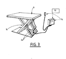
- the figure 3 illustrates an example of a lifting platform mounted on two pairs of pantographs 16 actuated by a system of hydraulic or pneumatic cylinders 26 controlled by an electric control box 14.
- the elevator plate is for example arranged / fixed on the bottom of the cavity 12 underground.
- any other suitable lifting system could be used for example a cable mechanism (s) and pulley (s).
- the support 6 In operational mode (when the station 1 is in configuration of filling tanks), the support 6 is in the low position (cf. figure 1 ). On the other hand, in order to facilitate maintenance, the support 6 can be raised ( figure 2 ).
- the station 1 comprises a member 14 for locking the support 6 in the low position.
- the locking member 14 is switchable between a first state in which the locking member 14 blocks the support 6 in its first lower position, that is to say prevents its movement towards the second high position and a second state in which the locking member 14 allows the displacement of the support 6 to the second high position.
- the locking member 14 may comprise a latch (mechanical stop) and / or an electric lock if appropriate.
- the refrigerant circuit 8 includes a zone 9 for quick connection / disconnection with the heat exchanger 5 to allow the disconnection / connection between the heat exchanger 5 and the refrigerant circuit 8.
- This zone 9 connection / disconnection comprises for example a set of quick connector (s) to connect fluidically or not the refrigerant circuit 8 with the heat exchanger 5.
- connection lines of the circuits 4, 8 may be flexible or semi-rigid connected to removable connectors in order to compensate for misalignment of the pipes.
- the distribution circuit 4 may also include a zone 11 for fast connection / disconnection with the heat exchanger (and / or the terminal 2) to enable the disconnection / connection between the heat exchanger (or terminal 2) and the pressurized gas distribution circuit.
- the locking member 14 is connected or cooperates with the zone 9 of fast connection / disconnection and is shaped to switch in its first state and block the support 6 in its first lower position as the exchanger 5 and / or a distribution terminal 2 is connected to the refrigerant circuit 8 or the distribution circuit 4.
- the locking system of the mechanism prevents any movement of the support 6 if one of the pipes is not disconnected.
- This mechanical system may be a rotary physical shutter mechanically or electrically coupled to the elevation system which allows the mounting of the support 6 only when all the connections 9, 11 are dismounted.
- the vertical position of the support 6 is determined by a system of cylinders 26 electrically controlled via a system 14 comprising for example an electrical cabinet and a push button manual terminal.
- a system 14 comprising for example an electrical cabinet and a push button manual terminal.
- the control of the lifting of the support 6 is inactivated by its electronic control logic for example as long as a sensor 10 indicates that the fluidic connections 9, 11 have not been disconnected.
- the sensor 10 may comprise at least one of: an electrical sensor, a pressure sensor, a switch, an optical sensor, etc.
- the station 1 may comprise a cover or flap 17 movable to access the zones 9, 11 of connection / disconnection in the cavity 12 when the support 6 is in the low position.
- the flap 17 is for example movably mounted (articulated) on the support 6.
- the locking member 14 and / or the lifting system of the support 6 is inaccessible or deactivated as long as the circuits 4, 8 remain fluidly connected to the terminal 2 and / or the exchanger 5.
Landscapes
- Engineering & Computer Science (AREA)
- Mechanical Engineering (AREA)
- General Engineering & Computer Science (AREA)
- Filling Or Discharging Of Gas Storage Vessels (AREA)
Abstract
Description
- La présente invention concerne une station de remplissage de gaz carburant.
- L'invention concerne plus particulièrement une station de remplissage de réservoirs avec du gaz carburant sous pression, la station comprenant une borne de distribution de gaz comportant au moins une conduite dont une extrémité est munie d'un raccord destiné à être relié fluidiquement à un réservoir à remplir, la borne de distribution étant reliée fluidiquement à une source de gaz via un circuit de distribution de gaz sous pression, la station comprenant au moins un échangeur de chaleur en échange thermique avec le gaz fourni à la borne de distribution pour refroidir ledit gaz, l'échangeur de chaleur étant situé sur le circuit de distribution.
- L'invention concerne notamment les stations de remplissage de réservoirs d'hydrogène sous pression de véhicules à pile à combustible. Ces stations de remplissages sont prévues pour remplir des réservoirs en quelques minutes à une pression élevée, par exemple 700 bar.
- Afin de permettre un remplissage rapide, l'hydrogène doit dans certains cas être refroidi avant d'être injecté dans le réservoir du véhicule. En effet, pour permettre le remplissage rapide des réservoirs, l'hydrogène doit par exemple être refroidi à une température pouvant aller jusqu'à -40°C. Pour ce faire, la station de remplissage comprend généralement un échangeur de chaleur prévu pour le refroidissement du gaz qui remplit le véhicule. L'échangeur de chaleur doit être le plus près possible de la borne de distribution d'hydrogène afin de garantir une distribution de gaz froid au plus tôt lors du remplissage (c'est-à-dire pour minimiser le temps de refroidissement de la tuyauterie entre l'échangeur et la borne de distribution)
- Les stations de remplissage d'hydrogène gazeux sont de plus en plus souvent intégrées dans des stations de ravitaillement existantes délivrant toutes sortes de carburant (essence notamment).
- Les bornes de distribution du carburant sont placées sur des ilots, c'est-à-dire des emplacements de la station ayant une surface au sol déterminée. La largeur de ces ilots est la plupart du temps déterminée par la largeur des bornes de distribution de carburant conventionnels. La longueur de ces ilots varie en fonction de la configuration du site, de l'ordre de 3 à 4 m par borne Les solutions proposées doivent être compactes.
- Une première solution connue consiste à disposer un échangeur de chaleur dans la borne de distribution. Cependant, dans ce cas, une intégration dans un ilot « standard » existant de la station est difficile car l'échangeur a un diamètre proche de la largeur de l'ilot et la longueur de l'ilot ne permet pas d'y intégrer une borne de distribution comprenant un échangeur.
- Dans une autre solution, l'échangeur de chaleur n'est pas placé dans la borne de distribution mais au plus près de la borne de distribution. Ceci impose de placer l'échangeur de chaleur dans l'ilot, dans un caveau sous-terrain. Cette solution nécessite cependant de prévoir de la place disponible pour l'échangeur dans la station et ne facilite pas sa maintenance et son installation (la borne de distribution de gaz et l'échangeur de refroidissement sont alors deux entités séparées qui doivent être intégrées sur le site). De plus, la tuyauterie entre la borne de distribution et l'échangeur doit être isolée ou refroidie, ce qui complique le montage sur site du système.
- Une autre solution consiste à déporter la mise en froid du gaz (l'échangeur de chaleur) par rapport à la borne de remplissage. Dans ce cas les conduites de transfert du gaz refroidi doivent être isolées thermiquement pour maintenir le froid entre l'échangeur déporté et la borne de distribution ou, dans autre une solution connue, les conduites doivent être activement refroidies par le liquide réfrigérant. Ceci augmente la complexité et le coût de la station du fait de la nécessité de prévoir pour le gaz un circuit à haute pression isolé et refroidi.
- Un but de la présente invention est de pallier tout ou partie des inconvénients de l'art antérieur relevés ci-dessus.
- A cette fin, la station selon l'invention, par ailleurs conforme à la définition générique qu'en donne le préambule ci-dessus, est essentiellement caractérisée en ce que la borne de distribution et l'échangeur de chaleur sont disposés sur un support commun, l'échangeur de chaleur étant disposé en dessous de la borne de distribution, le support étant mobile entre une première position basse dans laquelle la base de la borne repose au niveau du sol tandis que l'échangeur de chaleur est situé dans une cavité en dessous du niveau du sol et une seconde position haute dans laquelle l'échangeur est remonté de la cavité au niveau du sol ou au-dessus du niveau du sol.
- Ceci permet d'intégrer un échangeur de chaleur à la borne de distribution tout en possédant une empreinte au sol limitée et une accessibilité optimale.
- Par ailleurs, des modes de réalisation de l'invention peuvent comporter l'une ou plusieurs des caractéristiques suivantes :
- le support est relié à un mécanisme élévateur comprenant au moins l'un parmi : une table élévatrice, un ascenseur, un mécanisme à pantographe(s),
- le support est relié à un mécanisme élévateur mécanique et/ou hydraulique et/ou électrique,
- l'échangeur de chaleur est alimenté en frigories à partir d'une source froide de fluide frigorigène via un circuit de fluide frigorigène, le circuit de fluide frigorigène comprenant une zone de connexion/déconnexion rapide avec l'échangeur de chaleur pour permettre la déconnexion/connexion entre le l'échangeur de chaleur et le circuit de fluide frigorigène,
- la station comprend un organe de verrouillage du support en position basse, l'organe de verrouillage étant commutable entre un premier état dans lequel l'organe de verrouillage bloque le support dans sa première position basse, c'est-à-dire empêche son déplacement vers la seconde position haute et un second état dans lequel l'organe de verrouillage autorise le déplacement du support vers la seconde position haute,
- l'organe de verrouillage est relié ou coopère avec la zone de connexion/déconnexion rapide et est conformé pour commuter dans son premier état et bloquer le support dans sa première position basse tant que l'échangeur de chaleur est connecté au circuit de fluide frigorigène,
- le circuit de distribution comprend une zone de connexion/déconnexion rapide avec l'échangeur de chaleur et/ou la borne pour permettre la déconnexion/connexion entre d'une part le circuit de distribution et, d'autre part, l'échangeur de chaleur ou la borne,
- l'organe de verrouillage est relié ou coopère avec la zone de connexion/déconnexion rapide et est conformé pour commuter dans son premier état bloquant le support dans sa première position basse tant que l'échangeur de chaleur ou la borne est connecté au circuit de distribution,
- l'organe de verrouillage comprend un organe mécanique et/ou électrique relié au support mobile et relié physiquement ou électriquement à la zone de connexion rapide,
- le mécanisme élévateur comprend un organe d'actionnement à commande électrique via un logique électronique de traitement de données, la logique électronique intégrant l'organe de verrouillage.
- L'invention peut concerner également tout dispositif ou procédé alternatif comprenant toute combinaison des caractéristiques ci-dessus ou ci-dessous.
- D'autres particularités et avantages apparaîtront à la lecture de la description ci-après, faite en référence aux figures dans lesquelles :
- la
figure 1 représente une vue en coupe verticale, schématique et partielle, illustrant un exemple de réalisation d'une station de remplissage selon l'invention dans une première configuration abaissée, - la
figure 2 représente la station de lafigure 1 mais dans une seconde configuration relevée, - la
figure 3 représente une vue en perspective et schématique illustrant un exemple de réalisation possible d'un système de support mobile. - Les
figures 1 et 2 représentent un exemple de station de remplissage de réservoirs avec du gaz carburant sous pression (par exemple de l'hydrogène). - La station 1 comprend classiquement une borne 2 de distribution de gaz comportant au moins un flexible 3 dont une extrémité est munie d'un raccord destiné à être relié fluidiquement à un réservoir à remplir (par exemple un réservoir de véhicule automobile).
- La borne 2 de distribution est reliée fluidiquement à une source 13 de gaz sous pression via un circuit 4 de distribution de gaz sous pression. Par exemple, au moins une partie du circuit 4 de distribution est souterrain et/ou intégré dans un caniveau.
- La station 1 comprend un échangeur 5 de chaleur prévu classiquement pour refroidir le gaz sous pression qui remplit les réservoirs. L'échangeur 5 de chaleur est en échange thermique avec le gaz fourni à la borne 2 de distribution.
- Par exemple, la borne 2 est alimentée en gaz sous pression à partir d'un ou plusieurs réservoirs13 et éventuellement d'un compresseur 15. Bien entendu tout autre système de fourniture de gaz sous pression peut être prévu (système de plusieurs réservoirs en parallèle pour assurer un remplissage par équilibrages de pression successifs « en cascade », un système de production de gaz sous pression à partir d'un réservoir de gaz liquéfié et d'un vaporiseur...). La source 13 de gaz alimente la borne 2 de distribution via le circuit 4 de distribution et l'échangeur 5.
- L'échangeur 5 de chaleur est situé sur le circuit 4 de distribution par exemple juste en amont de la borne 2 de distribution (selon le sens d'écoulement du gaz).
- L'échangeur 5 de chaleur est par exemple un échangeur assurant un échange de chaleur entre le gaz à refroidir et un fluide de refroidissement. A cet effet, l'échangeur 5 de chaleur peut être alimenté en frigories à partir d'une source 7 froide via un circuit 8 de fluide frigorigène. Par exemple, le système de refroidissement et notamment l'échangeur peut comporter tout ou partie des caractéristiques décrites dans le document
FR2928716A1 - Selon une particularité avantageuse, la borne 2 de distribution et l'échangeur 5 de chaleur sont disposés sur un support 6 commun, l'échangeur 5 de chaleur étant disposé en dessous de la borne 2 de distribution et le support 6 est mobile entre une première position basse dans laquelle la base de la borne 2 repose au niveau du sol tandis que l'échangeur 5 de chaleur est situé dans une cavité 12 en dessous du niveau du sol et une seconde position haute dans laquelle l'échangeur 5 est remonté de la cavité 12 au niveau du sol ou au-dessus du niveau du sol.
- Par exemple, le support 6 peut comporter deux plateaux superposés sur lesquels sont disposés respectivement la borne 2 de remplissage et l'échangeur 5.
- Le support 6 est relié à un mécanisme 16, 26 élévateur permettant d'élever l'ensemble et de le redescendre.
- Le mécanisme comprend par exemple au moins l'un parmi : une table élévatrice, un ascenseur, un mécanisme à pantographe, un mécanisme à câble(s) et poulie(s).
- C'est-à-dire que le support 6 est relié à un mécanisme 16, 26 élévateur (ascenseur) mécanique et/ou hydraulique et/ou électrique.
- La
figure 3 illustre un exemple de plateau élévateur monté sur deux paires de pantographes 16 actionnés par un système des vérins 26 hydrauliques ou pneumatiques commandés par un boîtier 14 électrique de commande. Le plateau élévateur est par exemple disposé/fixé sur le fond de la cavité 12 souterraine. - Bien entendu tout autre système élévateur approprié pourrait être utilisé par exemple un mécanisme à câble(s) et poulie(s).
- En mode opérationnel (lorsque la station 1 est en configuration de remplir des réservoirs), le support 6 est en position basse (cf.
figure 1 ). En revanche, afin de faciliter la maintenance, le support 6 peut être relevé (figure 2 ). - De préférence la station 1 comprend un organe 14 de verrouillage du support 6 en position basse. L'organe 14 de verrouillage est commutable entre un premier état dans lequel l'organe 14 de verrouillage bloque le support 6 dans sa première position basse, c'est-à-dire empêche son déplacement vers la seconde position haute et un second état dans lequel l'organe 14 de verrouillage autorise le déplacement du support 6 vers la seconde position haute.
- L'organe 14 de verrouillage peut comporter un loquet (butée) mécanique et/ou un verrou électrique le cas échéant.
- De préférence également, le circuit 8 de fluide frigorigène comprend une zone 9 de connexion/déconnexion rapide avec l'échangeur 5 de chaleur pour permettre la déconnexion/connexion entre le l'échangeur 5 de chaleur et le circuit 8 de fluide frigorigène. Cette zone 9 de connexion/déconnexion comprend par exemple un ensemble de raccord(s) rapide(s) pour relier fluidiquement ou non le circuit 8 de fluide frigorigène avec l'échangeur 5 de chaleur.
- Les lignes de connexion des circuits 4, 8 peuvent être flexibles ou semi rigides connectées à des raccords démontables afin de compenser les écarts d'alignement des tuyauteries.
- De même, selon le même principe que ci-dessus, le circuit 4 de distribution peut également comprendre une zone 11 de connexion/déconnexion rapide avec l'échangeur 5 de chaleur (et/ou la borne 2) pour permettre la déconnexion/connexion entre le l'échangeur 5 de chaleur (ou la borne 2) et le circuit 8 de distribution de gaz sous pression.
- De préférence, l'organe 14 de verrouillage est relié ou coopère avec la zone 9 de connexion/déconnexion rapide et est conformé pour commuter dans son premier état et bloquer le support 6 dans sa première position basse tant que l'échangeur 5 et/ou a borne 2 de distribution est connecté au circuit 8 de fluide frigorigène ou au circuit 4 de distribution.
- C'est-à-dire que le système de verrouillage du mécanisme empêche tout mouvement du support 6 si une des tuyauteries n'est pas débranchée. Ce système mécanique peut être un obturateur physique rotatif couplé mécaniquement ou électriquement au système d'élévation qui n'autorise la montée du support 6 que lorsque tous les raccords 9, 11 sont démontés.
- Dans l'exemple de la
figure 3 la position verticale du support 6 est déterminée par un système de vérins 26 commandé électriquement via un système 14 comprenant par exemple une armoire électrique et une borne de manuelle à boutons poussoirs. Par exemple, la commande du levage du support 6 est inactivée par sa logique électronique de commande par exemple tant qu'un capteur 10 indique que les connexions fluidiques 9, 11 n'ont pas été débranchées. Le capteur 10 peut comprendre au moins un parmi : un capteur électrique, un capteur de pression, un interrupteur, un capteur optique... - De cette façon, l'échangeur 5 de chaleur (et la borne 2) doivent être détachés des circuits fluidiques les alimentant avant de surélever le support 6. Ceci permet d'éviter des accidents et ruptures de câbles par exemple.
- La station 1 peut comporter un capot ou volet 17 mobile permettant d'accéder aux zones 9, 11 de connexion/déconnexion dans la cavité 12 lorsque le support 6 est en position basse. Le volet 17 est par exemple monté mobile (articulé) sur le support 6.
- Par exemple, l'organe 14 de verrouillage et/ou le système de levage du support 6 est inaccessible ou désactivé tant que les circuits 4, 8 restent connectés fluidiquement à la borne 2 et/ou à l'échangeur 5.
- La station 1 présente de nombreux avantage et notamment :
- une grande compacité,
- un coût d'installation réduit (l'échangeur 5 de chaleur pouvant être assemblé à l'avance en usine avec la borne 2 de distribution),
- une disposition de l'échangeur 5 de chaleur au plus près de la borne 2 de remplissage ce qui permet de refroidir efficacement le gaz,
- un accès aisé à l'échangeur 5 de chaleur pour sa maintenance (par rapport notamment à une solution enterrée fixe).
Claims (10)
- Station de remplissage de réservoirs avec du gaz carburant sous pression, la station (1) comprenant une borne (2) de distribution de gaz comportant au moins une conduite (3) dont une extrémité est munie d'un raccord destiné à être relié fluidiquement à un réservoir à remplir, la borne (2) de distribution étant reliée fluidiquement à une source (13) de gaz via un circuit (4) de distribution de gaz sous pression, la station (1) comprenant au moins un échangeur (5) de chaleur en échange thermique avec le gaz fourni à la borne (2) de distribution pour refroidir ledit gaz, l'échangeur (5) de chaleur étant situé sur le circuit (4) de distribution, caractérisé en ce que la borne (2) de distribution et l'échangeur (5) de chaleur sont disposés sur un support (6) commun, l'échangeur (5) de chaleur étant disposé en dessous de la borne (2) de distribution et en ce que le support (6) est mobile entre une première position basse dans laquelle la base de la borne (2) repose au niveau du sol tandis que l'échangeur (5) de chaleur est situé dans une cavité (12) en dessous du niveau du sol et une seconde position haute dans laquelle l'échangeur (5) est remonté de la cavité (12) au niveau du sol ou au-dessus du niveau du sol.
- Station selon la revendication 1, caractérisée en ce que le support (6) est relié à un mécanisme (16, 26) élévateur comprenant au moins l'un parmi : une table élévatrice, un ascenseur, un mécanisme à pantographe(s).
- Station selon la revendication 1 ou 2, caractérisée en ce que le support (6) est relié à un mécanisme (16, 26) élévateur mécanique et/ou hydraulique et/ou électrique.
- Station selon l'une quelconque des revendications 1 à 3, caractérisée en ce que l'échangeur (5) de chaleur est alimenté en frigories à partir d'une source (7) froide de fluide frigorigène via un circuit (8) de fluide frigorigène et en ce que le circuit (8) de fluide frigorigène comprend une zone (9) de connexion/déconnexion rapide avec l'échangeur (5) de chaleur pour permettre la déconnexion/connexion entre le l'échangeur (5) de chaleur et le circuit (8) de fluide frigorigène.
- Station selon l'une quelconque des revendications 1 à 4, caractérisée en ce que la station (1) comprend un organe (14) de verrouillage du support (6) en position basse, l'organe (14) de verrouillage étant commutable entre un premier état dans lequel l'organe (14) de verrouillage bloque le support (6) dans sa première position basse, c'est-à-dire empêche son déplacement vers la seconde position haute et un second état dans lequel l'organe (14) de verrouillage autorise le déplacement du support (6) vers la seconde position haute.
- Station selon les revendications 4 et 5, caractérisée en ce que l'organe (14) de verrouillage est relié ou coopère avec la zone (9) de connexion/déconnexion rapide et est conformé pour commuter dans son premier état et bloquer le support (6) dans sa première position basse tant que l'échangeur (5) de chaleur est connecté au circuit (8) de fluide frigorigène.
- Station selon l'une quelconque des revendications 1 à 6, caractérisée en ce que le circuit (4) de distribution comprend une zone (11) de connexion/déconnexion rapide avec l'échangeur (5) de chaleur et/ou la borne (2) pour permettre la déconnexion/connexion entre d'une part le circuit (8) de distribution et, d'autre part, l'échangeur (5) de chaleur ou la borne (2).
- Station selon les revendications 5 et 7, caractérisée en ce que l'organe (14) de verrouillage est relié ou coopère avec la zone (11) de connexion/déconnexion rapide et est conformé pour commuter dans son premier état bloquant le support (6) dans sa première position basse tant que l'échangeur (5) de chaleur ou la borne (2) est connecté au circuit (4) de distribution.
- Station selon l'une quelconque des revendications 5, 6 ou 8, caractérisée en ce que l'organe (14) de verrouillage comprend un organe mécanique et/ou électrique relié au support (6) mobile et relié physiquement ou électriquement à la zone de connexion rapide (9, 11).
- Station selon la revendication 9, caractérisé en ce que le mécanisme (16, 26) élévateur comprend un organe (26) d'actionnement à commande électrique via un logique (14) électronique de traitement de données et en ce que la logique (14) électronique intègre l'organe (14) de verrouillage.
Applications Claiming Priority (1)
| Application Number | Priority Date | Filing Date | Title |
|---|---|---|---|
| FR1454816A FR3021727B1 (fr) | 2014-05-28 | 2014-05-28 | Station de remplissage de reservoirs de gaz sous pression |
Publications (2)
| Publication Number | Publication Date |
|---|---|
| EP2955427A1 true EP2955427A1 (fr) | 2015-12-16 |
| EP2955427B1 EP2955427B1 (fr) | 2018-05-09 |
Family
ID=51168239
Family Applications (1)
| Application Number | Title | Priority Date | Filing Date |
|---|---|---|---|
| EP15159230.0A Not-in-force EP2955427B1 (fr) | 2014-05-28 | 2015-03-16 | Station de remplissage de réservoirs de gaz sous pression |
Country Status (9)
| Country | Link |
|---|---|
| US (1) | US20150345703A1 (fr) |
| EP (1) | EP2955427B1 (fr) |
| JP (1) | JP6576691B2 (fr) |
| KR (1) | KR20150137005A (fr) |
| CN (1) | CN105318183B (fr) |
| CA (1) | CA2885511A1 (fr) |
| DK (1) | DK2955427T3 (fr) |
| FR (1) | FR3021727B1 (fr) |
| NO (1) | NO2955427T3 (fr) |
Cited By (1)
| Publication number | Priority date | Publication date | Assignee | Title |
|---|---|---|---|---|
| WO2022248295A1 (fr) * | 2021-05-28 | 2022-12-01 | L'air Liquide, Societe Anonyme Pour L'etude Et L'exploitation Des Procedes Georges Claude | Installation de transfert de fluide |
Families Citing this family (3)
| Publication number | Priority date | Publication date | Assignee | Title |
|---|---|---|---|---|
| FR3067092B1 (fr) * | 2017-05-31 | 2020-08-14 | L'air Liquide Sa Pour L'etude Et L'exploitation Des Procedes Georges Claude | Station et procede de remplissage de reservoir(s) de gaz sous pression |
| CN108413245A (zh) * | 2018-05-24 | 2018-08-17 | 浙江智海化工设备工程有限公司 | 一种低温液体运输槽车中带压气体回收系统及回收方法 |
| FR3090812B1 (fr) * | 2018-12-21 | 2022-01-07 | Grtgaz | Poste de détente d’un gaz |
Citations (3)
| Publication number | Priority date | Publication date | Assignee | Title |
|---|---|---|---|---|
| EP1593905A2 (fr) * | 2002-09-25 | 2005-11-09 | Taiyo Nippon Sanso Corporation | Dispositif et methode pour remplir un reservoir de carburant avec un gaz comprime, comme de l'hydrogene, en controlant le debit et la temperature |
| FR2928716A1 (fr) | 2008-03-11 | 2009-09-18 | Air Liquide | Dispositif et procede de remplissage d'un gaz sous pression dans un reservoir |
| US20120024892A1 (en) * | 2010-07-27 | 2012-02-02 | Jack Francis Bartlett | Fuel or def dispenser having fluid temperature conditioning and control system |
Family Cites Families (14)
| Publication number | Priority date | Publication date | Assignee | Title |
|---|---|---|---|---|
| US1867602A (en) * | 1930-12-01 | 1932-07-19 | Louis C Stukenborg | Fueling system |
| DE721995C (de) * | 1940-11-05 | 1942-06-25 | Ruhrchemie Ag | Vorrichtung zum Tanken von unter Druck stehenden verfluessigten Gasen |
| US2642957A (en) * | 1948-08-27 | 1953-06-23 | Wattpar Corp | Gasoline dispensing system for airplanes |
| IT1102377B (it) * | 1978-02-15 | 1985-10-07 | Cutore Gaetano | Complesso di collegamento di una sorgente fissa di un liquido sotto pressione e un apparecchio di erogazione mobile verticalmente rispetto a essa |
| IT1101971B (it) * | 1978-02-23 | 1985-10-07 | Cutore Gaetano | Complesso perfezionato a scomparsa totale per il rifornimento di carburante ad aeromobili |
| US4531558A (en) * | 1983-04-13 | 1985-07-30 | Michigan Consolidated Gas Co. | Gaseous fuel refueling apparatus |
| DE4040077A1 (de) * | 1990-12-14 | 1992-06-17 | Walther Carl Kurt Gmbh | In betankungsleitungen oder dergleichen einsetzbare kupplung |
| JPH04137171U (ja) * | 1991-06-13 | 1992-12-21 | 東立エンジニアリング株式会社 | 地下格納庫 |
| US6983196B2 (en) * | 2000-10-27 | 2006-01-03 | Delaware Capital Formation, Inc. | Electronically controlled vehicle lift and vehicle service system |
| US6622758B2 (en) * | 2001-02-08 | 2003-09-23 | Chart Inc. | Interlock for cryogenic liquid off-loading systems |
| JP2006182530A (ja) * | 2004-12-28 | 2006-07-13 | Tatsuji Ishikawa | 車両点検用リフトとそれを備えた車検設備 |
| US7497191B2 (en) * | 2006-02-06 | 2009-03-03 | Eden Innovations Ltd. | System and method for producing, dispensing, using and monitoring a hydrogen enriched fuel |
| JP2008074342A (ja) * | 2006-09-25 | 2008-04-03 | Hitachi Constr Mach Co Ltd | 作業機械の燃料タンク |
| US7938150B2 (en) * | 2007-06-11 | 2011-05-10 | Honda Motor Co, Ltd | Station side cooling for refueling vehicle storage tanks with high pressure fuel |
-
2014
- 2014-05-28 FR FR1454816A patent/FR3021727B1/fr not_active Expired - Fee Related
-
2015
- 2015-03-16 EP EP15159230.0A patent/EP2955427B1/fr not_active Not-in-force
- 2015-03-16 NO NO15159230A patent/NO2955427T3/no unknown
- 2015-03-16 DK DK15159230.0T patent/DK2955427T3/en active
- 2015-03-18 CA CA2885511A patent/CA2885511A1/fr not_active Abandoned
- 2015-05-20 CN CN201510259829.8A patent/CN105318183B/zh active Active
- 2015-05-22 KR KR1020150071609A patent/KR20150137005A/ko not_active Ceased
- 2015-05-27 US US14/722,977 patent/US20150345703A1/en not_active Abandoned
- 2015-05-27 JP JP2015107649A patent/JP6576691B2/ja active Active
Patent Citations (3)
| Publication number | Priority date | Publication date | Assignee | Title |
|---|---|---|---|---|
| EP1593905A2 (fr) * | 2002-09-25 | 2005-11-09 | Taiyo Nippon Sanso Corporation | Dispositif et methode pour remplir un reservoir de carburant avec un gaz comprime, comme de l'hydrogene, en controlant le debit et la temperature |
| FR2928716A1 (fr) | 2008-03-11 | 2009-09-18 | Air Liquide | Dispositif et procede de remplissage d'un gaz sous pression dans un reservoir |
| US20120024892A1 (en) * | 2010-07-27 | 2012-02-02 | Jack Francis Bartlett | Fuel or def dispenser having fluid temperature conditioning and control system |
Cited By (3)
| Publication number | Priority date | Publication date | Assignee | Title |
|---|---|---|---|---|
| WO2022248295A1 (fr) * | 2021-05-28 | 2022-12-01 | L'air Liquide, Societe Anonyme Pour L'etude Et L'exploitation Des Procedes Georges Claude | Installation de transfert de fluide |
| FR3123340A1 (fr) * | 2021-05-28 | 2022-12-02 | L'air Liquide, Societe Anonyme Pour L'etude Et L'exploitation Des Procedes Georges Claude | Installation de transfert de fluide |
| US12474019B2 (en) | 2021-05-28 | 2025-11-18 | L'air Liquide, Societe Anonyme Pour L'etude Et L'exploitation Des Procedes Georges Claude | Fluid transfer installation |
Also Published As
| Publication number | Publication date |
|---|---|
| DK2955427T3 (en) | 2018-06-14 |
| FR3021727A1 (fr) | 2015-12-04 |
| US20150345703A1 (en) | 2015-12-03 |
| KR20150137005A (ko) | 2015-12-08 |
| EP2955427B1 (fr) | 2018-05-09 |
| JP6576691B2 (ja) | 2019-09-18 |
| NO2955427T3 (fr) | 2018-10-06 |
| CN105318183B (zh) | 2019-07-26 |
| JP2015227725A (ja) | 2015-12-17 |
| CN105318183A (zh) | 2016-02-10 |
| FR3021727B1 (fr) | 2016-05-20 |
| CA2885511A1 (fr) | 2015-11-28 |
Similar Documents
| Publication | Publication Date | Title |
|---|---|---|
| EP2955427B1 (fr) | Station de remplissage de réservoirs de gaz sous pression | |
| EP3942220B1 (fr) | Dispositif et procédé de stockage et de fourniture de carburant fluide | |
| US11326741B2 (en) | Cryogenic storage vessel | |
| US8164302B2 (en) | System for replenishing energy sources onboard different types of automatic vehicles | |
| FR2975748A1 (fr) | Dispositif sous-marin de transport d'hydrocarbures et de regulation de leur temperature | |
| EP2618039B1 (fr) | Elément modulaire de distribution de gaz sous pression et installation correspondante | |
| EP3759564B1 (fr) | Distributeur mobile d'hydrogène pour véhicules à pile à combustible | |
| US20150276130A1 (en) | Method and System for a Submerged Pump | |
| FR2485158A1 (fr) | Procede pour l'augmentation de la duree de conservation d'hydrogene a l'etat liquide dans un reservoir et dispositif pour la mise en oeuvre dudit procede | |
| EP4455537B1 (fr) | Dispositif de fourniture de fluide cryogénique et installation de remplissage de réservoirs | |
| EP4075048A1 (fr) | Dispositif de stockage et de fourniture de fluide, véhicule et procédé comportant un tel dispositif | |
| EP2782435B1 (fr) | Convertisseur de puissance électrique pour un véhicule ferroviaire | |
| FR2978119A1 (fr) | Navire equipe d'un systeme de stockage de carburant et procede correspondant | |
| EP4437261A1 (fr) | Réservoir de stockage de gaz liquéfié et procédé de transfert de fluide | |
| FR2947230A1 (fr) | Dispositif modulaire de generation de puissance pour vehicule | |
| EP1703610B1 (fr) | Structure de connexion électrique pour élément supraconducteur | |
| KR102094023B1 (ko) | 가스 충전 장치 | |
| FR3067820B1 (fr) | Installation de radioastronomie | |
| JP4599153B2 (ja) | 自動車用の液化ガス燃料供給装置 | |
| CN218626408U (zh) | 带有泄漏保护的独立储罐垂向支撑装置 | |
| CN109229998B (zh) | 油罐、其温度控制方法、撬装加油机构以及油罐车 | |
| US20140261865A1 (en) | Methods and apparatuses for recovering, storing, transporting and using compressed gas | |
| US20140261866A1 (en) | Methods and apparatuses for recovering, storing, transporting and using compressed gas | |
| EP4484818A1 (fr) | Dispositif de guidage pour tour de chargement et/ou de déchargement de fluide cryogénique | |
| FR3073675A1 (fr) | Systeme de generation d'energie electrique nomade pour un aeronef comprenant une pile a combustible |
Legal Events
| Date | Code | Title | Description |
|---|---|---|---|
| PUAI | Public reference made under article 153(3) epc to a published international application that has entered the european phase |
Free format text: ORIGINAL CODE: 0009012 |
|
| AK | Designated contracting states |
Kind code of ref document: A1 Designated state(s): AL AT BE BG CH CY CZ DE DK EE ES FI FR GB GR HR HU IE IS IT LI LT LU LV MC MK MT NL NO PL PT RO RS SE SI SK SM TR |
|
| AX | Request for extension of the european patent |
Extension state: BA ME |
|
| 17P | Request for examination filed |
Effective date: 20160616 |
|
| RBV | Designated contracting states (corrected) |
Designated state(s): AL AT BE BG CH CY CZ DE DK EE ES FI FR GB GR HR HU IE IS IT LI LT LU LV MC MK MT NL NO PL PT RO RS SE SI SK SM TR |
|
| GRAP | Despatch of communication of intention to grant a patent |
Free format text: ORIGINAL CODE: EPIDOSNIGR1 |
|
| STAA | Information on the status of an ep patent application or granted ep patent |
Free format text: STATUS: GRANT OF PATENT IS INTENDED |
|
| RIC1 | Information provided on ipc code assigned before grant |
Ipc: F17C 5/06 20060101ALI20171116BHEP Ipc: F17C 13/02 20060101ALI20171116BHEP Ipc: F17C 5/00 20060101AFI20171116BHEP |
|
| INTG | Intention to grant announced |
Effective date: 20171213 |
|
| GRAS | Grant fee paid |
Free format text: ORIGINAL CODE: EPIDOSNIGR3 |
|
| GRAA | (expected) grant |
Free format text: ORIGINAL CODE: 0009210 |
|
| STAA | Information on the status of an ep patent application or granted ep patent |
Free format text: STATUS: THE PATENT HAS BEEN GRANTED |
|
| AK | Designated contracting states |
Kind code of ref document: B1 Designated state(s): AL AT BE BG CH CY CZ DE DK EE ES FI FR GB GR HR HU IE IS IT LI LT LU LV MC MK MT NL NO PL PT RO RS SE SI SK SM TR |
|
| REG | Reference to a national code |
Ref country code: GB Ref legal event code: FG4D Free format text: NOT ENGLISH |
|
| REG | Reference to a national code |
Ref country code: CH Ref legal event code: EP Ref country code: AT Ref legal event code: REF Ref document number: 997900 Country of ref document: AT Kind code of ref document: T Effective date: 20180515 |
|
| REG | Reference to a national code |
Ref country code: IE Ref legal event code: FG4D Free format text: LANGUAGE OF EP DOCUMENT: FRENCH |
|
| REG | Reference to a national code |
Ref country code: DE Ref legal event code: R096 Ref document number: 602015010846 Country of ref document: DE |
|
| REG | Reference to a national code |
Ref country code: DK Ref legal event code: T3 Effective date: 20180607 |
|
| REG | Reference to a national code |
Ref country code: NO Ref legal event code: T2 Effective date: 20180509 |
|
| REG | Reference to a national code |
Ref country code: NL Ref legal event code: MP Effective date: 20180509 |
|
| REG | Reference to a national code |
Ref country code: LT Ref legal event code: MG4D |
|
| PG25 | Lapsed in a contracting state [announced via postgrant information from national office to epo] |
Ref country code: SE Free format text: LAPSE BECAUSE OF FAILURE TO SUBMIT A TRANSLATION OF THE DESCRIPTION OR TO PAY THE FEE WITHIN THE PRESCRIBED TIME-LIMIT Effective date: 20180509 Ref country code: LT Free format text: LAPSE BECAUSE OF FAILURE TO SUBMIT A TRANSLATION OF THE DESCRIPTION OR TO PAY THE FEE WITHIN THE PRESCRIBED TIME-LIMIT Effective date: 20180509 Ref country code: BG Free format text: LAPSE BECAUSE OF FAILURE TO SUBMIT A TRANSLATION OF THE DESCRIPTION OR TO PAY THE FEE WITHIN THE PRESCRIBED TIME-LIMIT Effective date: 20180809 Ref country code: FI Free format text: LAPSE BECAUSE OF FAILURE TO SUBMIT A TRANSLATION OF THE DESCRIPTION OR TO PAY THE FEE WITHIN THE PRESCRIBED TIME-LIMIT Effective date: 20180509 Ref country code: ES Free format text: LAPSE BECAUSE OF FAILURE TO SUBMIT A TRANSLATION OF THE DESCRIPTION OR TO PAY THE FEE WITHIN THE PRESCRIBED TIME-LIMIT Effective date: 20180509 |
|
| PG25 | Lapsed in a contracting state [announced via postgrant information from national office to epo] |
Ref country code: LV Free format text: LAPSE BECAUSE OF FAILURE TO SUBMIT A TRANSLATION OF THE DESCRIPTION OR TO PAY THE FEE WITHIN THE PRESCRIBED TIME-LIMIT Effective date: 20180509 Ref country code: HR Free format text: LAPSE BECAUSE OF FAILURE TO SUBMIT A TRANSLATION OF THE DESCRIPTION OR TO PAY THE FEE WITHIN THE PRESCRIBED TIME-LIMIT Effective date: 20180509 Ref country code: RS Free format text: LAPSE BECAUSE OF FAILURE TO SUBMIT A TRANSLATION OF THE DESCRIPTION OR TO PAY THE FEE WITHIN THE PRESCRIBED TIME-LIMIT Effective date: 20180509 Ref country code: NL Free format text: LAPSE BECAUSE OF FAILURE TO SUBMIT A TRANSLATION OF THE DESCRIPTION OR TO PAY THE FEE WITHIN THE PRESCRIBED TIME-LIMIT Effective date: 20180509 Ref country code: GR Free format text: LAPSE BECAUSE OF FAILURE TO SUBMIT A TRANSLATION OF THE DESCRIPTION OR TO PAY THE FEE WITHIN THE PRESCRIBED TIME-LIMIT Effective date: 20180810 |
|
| REG | Reference to a national code |
Ref country code: AT Ref legal event code: MK05 Ref document number: 997900 Country of ref document: AT Kind code of ref document: T Effective date: 20180509 |
|
| PG25 | Lapsed in a contracting state [announced via postgrant information from national office to epo] |
Ref country code: CZ Free format text: LAPSE BECAUSE OF FAILURE TO SUBMIT A TRANSLATION OF THE DESCRIPTION OR TO PAY THE FEE WITHIN THE PRESCRIBED TIME-LIMIT Effective date: 20180509 Ref country code: RO Free format text: LAPSE BECAUSE OF FAILURE TO SUBMIT A TRANSLATION OF THE DESCRIPTION OR TO PAY THE FEE WITHIN THE PRESCRIBED TIME-LIMIT Effective date: 20180509 Ref country code: PL Free format text: LAPSE BECAUSE OF FAILURE TO SUBMIT A TRANSLATION OF THE DESCRIPTION OR TO PAY THE FEE WITHIN THE PRESCRIBED TIME-LIMIT Effective date: 20180509 Ref country code: SK Free format text: LAPSE BECAUSE OF FAILURE TO SUBMIT A TRANSLATION OF THE DESCRIPTION OR TO PAY THE FEE WITHIN THE PRESCRIBED TIME-LIMIT Effective date: 20180509 Ref country code: EE Free format text: LAPSE BECAUSE OF FAILURE TO SUBMIT A TRANSLATION OF THE DESCRIPTION OR TO PAY THE FEE WITHIN THE PRESCRIBED TIME-LIMIT Effective date: 20180509 Ref country code: AT Free format text: LAPSE BECAUSE OF FAILURE TO SUBMIT A TRANSLATION OF THE DESCRIPTION OR TO PAY THE FEE WITHIN THE PRESCRIBED TIME-LIMIT Effective date: 20180509 |
|
| REG | Reference to a national code |
Ref country code: DE Ref legal event code: R097 Ref document number: 602015010846 Country of ref document: DE |
|
| PG25 | Lapsed in a contracting state [announced via postgrant information from national office to epo] |
Ref country code: SM Free format text: LAPSE BECAUSE OF FAILURE TO SUBMIT A TRANSLATION OF THE DESCRIPTION OR TO PAY THE FEE WITHIN THE PRESCRIBED TIME-LIMIT Effective date: 20180509 Ref country code: IT Free format text: LAPSE BECAUSE OF FAILURE TO SUBMIT A TRANSLATION OF THE DESCRIPTION OR TO PAY THE FEE WITHIN THE PRESCRIBED TIME-LIMIT Effective date: 20180509 |
|
| PLBE | No opposition filed within time limit |
Free format text: ORIGINAL CODE: 0009261 |
|
| STAA | Information on the status of an ep patent application or granted ep patent |
Free format text: STATUS: NO OPPOSITION FILED WITHIN TIME LIMIT |
|
| 26N | No opposition filed |
Effective date: 20190212 |
|
| PG25 | Lapsed in a contracting state [announced via postgrant information from national office to epo] |
Ref country code: SI Free format text: LAPSE BECAUSE OF FAILURE TO SUBMIT A TRANSLATION OF THE DESCRIPTION OR TO PAY THE FEE WITHIN THE PRESCRIBED TIME-LIMIT Effective date: 20180509 |
|
| PG25 | Lapsed in a contracting state [announced via postgrant information from national office to epo] |
Ref country code: MC Free format text: LAPSE BECAUSE OF FAILURE TO SUBMIT A TRANSLATION OF THE DESCRIPTION OR TO PAY THE FEE WITHIN THE PRESCRIBED TIME-LIMIT Effective date: 20180509 |
|
| REG | Reference to a national code |
Ref country code: CH Ref legal event code: PL |
|
| PG25 | Lapsed in a contracting state [announced via postgrant information from national office to epo] |
Ref country code: LU Free format text: LAPSE BECAUSE OF NON-PAYMENT OF DUE FEES Effective date: 20190316 Ref country code: AL Free format text: LAPSE BECAUSE OF FAILURE TO SUBMIT A TRANSLATION OF THE DESCRIPTION OR TO PAY THE FEE WITHIN THE PRESCRIBED TIME-LIMIT Effective date: 20180509 |
|
| PG25 | Lapsed in a contracting state [announced via postgrant information from national office to epo] |
Ref country code: CH Free format text: LAPSE BECAUSE OF NON-PAYMENT OF DUE FEES Effective date: 20190331 Ref country code: LI Free format text: LAPSE BECAUSE OF NON-PAYMENT OF DUE FEES Effective date: 20190331 Ref country code: IE Free format text: LAPSE BECAUSE OF NON-PAYMENT OF DUE FEES Effective date: 20190316 |
|
| PG25 | Lapsed in a contracting state [announced via postgrant information from national office to epo] |
Ref country code: TR Free format text: LAPSE BECAUSE OF FAILURE TO SUBMIT A TRANSLATION OF THE DESCRIPTION OR TO PAY THE FEE WITHIN THE PRESCRIBED TIME-LIMIT Effective date: 20180509 |
|
| PG25 | Lapsed in a contracting state [announced via postgrant information from national office to epo] |
Ref country code: PT Free format text: LAPSE BECAUSE OF FAILURE TO SUBMIT A TRANSLATION OF THE DESCRIPTION OR TO PAY THE FEE WITHIN THE PRESCRIBED TIME-LIMIT Effective date: 20180910 Ref country code: MT Free format text: LAPSE BECAUSE OF FAILURE TO SUBMIT A TRANSLATION OF THE DESCRIPTION OR TO PAY THE FEE WITHIN THE PRESCRIBED TIME-LIMIT Effective date: 20180509 |
|
| PG25 | Lapsed in a contracting state [announced via postgrant information from national office to epo] |
Ref country code: CY Free format text: LAPSE BECAUSE OF FAILURE TO SUBMIT A TRANSLATION OF THE DESCRIPTION OR TO PAY THE FEE WITHIN THE PRESCRIBED TIME-LIMIT Effective date: 20180509 |
|
| PG25 | Lapsed in a contracting state [announced via postgrant information from national office to epo] |
Ref country code: IS Free format text: LAPSE BECAUSE OF FAILURE TO SUBMIT A TRANSLATION OF THE DESCRIPTION OR TO PAY THE FEE WITHIN THE PRESCRIBED TIME-LIMIT Effective date: 20180909 |
|
| PG25 | Lapsed in a contracting state [announced via postgrant information from national office to epo] |
Ref country code: HU Free format text: LAPSE BECAUSE OF FAILURE TO SUBMIT A TRANSLATION OF THE DESCRIPTION OR TO PAY THE FEE WITHIN THE PRESCRIBED TIME-LIMIT; INVALID AB INITIO Effective date: 20150316 |
|
| PG25 | Lapsed in a contracting state [announced via postgrant information from national office to epo] |
Ref country code: MK Free format text: LAPSE BECAUSE OF FAILURE TO SUBMIT A TRANSLATION OF THE DESCRIPTION OR TO PAY THE FEE WITHIN THE PRESCRIBED TIME-LIMIT Effective date: 20180509 |
|
| PGFP | Annual fee paid to national office [announced via postgrant information from national office to epo] |
Ref country code: DE Payment date: 20240320 Year of fee payment: 10 Ref country code: GB Payment date: 20240320 Year of fee payment: 10 |
|
| PGFP | Annual fee paid to national office [announced via postgrant information from national office to epo] |
Ref country code: NO Payment date: 20240322 Year of fee payment: 10 Ref country code: FR Payment date: 20240328 Year of fee payment: 10 Ref country code: DK Payment date: 20240326 Year of fee payment: 10 Ref country code: BE Payment date: 20240320 Year of fee payment: 10 |
|
| REG | Reference to a national code |
Ref country code: DE Ref legal event code: R119 Ref document number: 602015010846 Country of ref document: DE |
|
| REG | Reference to a national code |
Ref country code: DK Ref legal event code: EBP Effective date: 20250331 |
|
| GBPC | Gb: european patent ceased through non-payment of renewal fee |
Effective date: 20250316 |
|
| REG | Reference to a national code |
Ref country code: BE Ref legal event code: MM Effective date: 20250331 |
|
| PG25 | Lapsed in a contracting state [announced via postgrant information from national office to epo] |
Ref country code: DE Free format text: LAPSE BECAUSE OF NON-PAYMENT OF DUE FEES Effective date: 20251001 |
|
| PG25 | Lapsed in a contracting state [announced via postgrant information from national office to epo] |
Ref country code: GB Free format text: LAPSE BECAUSE OF NON-PAYMENT OF DUE FEES Effective date: 20250316 |
|
| PG25 | Lapsed in a contracting state [announced via postgrant information from national office to epo] |
Ref country code: NO Free format text: LAPSE BECAUSE OF NON-PAYMENT OF DUE FEES Effective date: 20250331 |
|
| PG25 | Lapsed in a contracting state [announced via postgrant information from national office to epo] |
Ref country code: FR Free format text: LAPSE BECAUSE OF NON-PAYMENT OF DUE FEES Effective date: 20250331 |
|
| PG25 | Lapsed in a contracting state [announced via postgrant information from national office to epo] |
Ref country code: BE Free format text: LAPSE BECAUSE OF NON-PAYMENT OF DUE FEES Effective date: 20250331 |
|
| PG25 | Lapsed in a contracting state [announced via postgrant information from national office to epo] |
Ref country code: DK Free format text: LAPSE BECAUSE OF NON-PAYMENT OF DUE FEES Effective date: 20250331 |