EP2955239B1 - Procede et installation de chauffage pour le chauffage en serie de platines en tole par formation de differentes zones de temperature - Google Patents
Procede et installation de chauffage pour le chauffage en serie de platines en tole par formation de differentes zones de temperature Download PDFInfo
- Publication number
- EP2955239B1 EP2955239B1 EP15171386.4A EP15171386A EP2955239B1 EP 2955239 B1 EP2955239 B1 EP 2955239B1 EP 15171386 A EP15171386 A EP 15171386A EP 2955239 B1 EP2955239 B1 EP 2955239B1
- Authority
- EP
- European Patent Office
- Prior art keywords
- inductor
- heating
- blanks
- sheet steel
- sheet metal
- Prior art date
- Legal status (The legal status is an assumption and is not a legal conclusion. Google has not performed a legal analysis and makes no representation as to the accuracy of the status listed.)
- Active
Links
Images


Classifications
-
- C—CHEMISTRY; METALLURGY
- C21—METALLURGY OF IRON
- C21D—MODIFYING THE PHYSICAL STRUCTURE OF FERROUS METALS; GENERAL DEVICES FOR HEAT TREATMENT OF FERROUS OR NON-FERROUS METALS OR ALLOYS; MAKING METAL MALLEABLE, e.g. BY DECARBURISATION OR TEMPERING
- C21D1/00—General methods or devices for heat treatment, e.g. annealing, hardening, quenching or tempering
- C21D1/62—Quenching devices
- C21D1/673—Quenching devices for die quenching
-
- C—CHEMISTRY; METALLURGY
- C21—METALLURGY OF IRON
- C21D—MODIFYING THE PHYSICAL STRUCTURE OF FERROUS METALS; GENERAL DEVICES FOR HEAT TREATMENT OF FERROUS OR NON-FERROUS METALS OR ALLOYS; MAKING METAL MALLEABLE, e.g. BY DECARBURISATION OR TEMPERING
- C21D1/00—General methods or devices for heat treatment, e.g. annealing, hardening, quenching or tempering
- C21D1/34—Methods of heating
- C21D1/42—Induction heating
-
- C—CHEMISTRY; METALLURGY
- C21—METALLURGY OF IRON
- C21D—MODIFYING THE PHYSICAL STRUCTURE OF FERROUS METALS; GENERAL DEVICES FOR HEAT TREATMENT OF FERROUS OR NON-FERROUS METALS OR ALLOYS; MAKING METAL MALLEABLE, e.g. BY DECARBURISATION OR TEMPERING
- C21D9/00—Heat treatment, e.g. annealing, hardening, quenching or tempering, adapted for particular articles; Furnaces therefor
- C21D9/52—Heat treatment, e.g. annealing, hardening, quenching or tempering, adapted for particular articles; Furnaces therefor for wires; for strips ; for rods of unlimited length
- C21D9/54—Furnaces for treating strips or wire
- C21D9/56—Continuous furnaces for strip or wire
- C21D9/60—Continuous furnaces for strip or wire with induction heating
-
- H—ELECTRICITY
- H05—ELECTRIC TECHNIQUES NOT OTHERWISE PROVIDED FOR
- H05B—ELECTRIC HEATING; ELECTRIC LIGHT SOURCES NOT OTHERWISE PROVIDED FOR; CIRCUIT ARRANGEMENTS FOR ELECTRIC LIGHT SOURCES, IN GENERAL
- H05B6/00—Heating by electric, magnetic or electromagnetic fields
- H05B6/02—Induction heating
- H05B6/10—Induction heating apparatus, other than furnaces, for specific applications
- H05B6/101—Induction heating apparatus, other than furnaces, for specific applications for local heating of metal pieces
- H05B6/102—Induction heating apparatus, other than furnaces, for specific applications for local heating of metal pieces the metal pieces being rotated while induction heated
-
- H—ELECTRICITY
- H05—ELECTRIC TECHNIQUES NOT OTHERWISE PROVIDED FOR
- H05B—ELECTRIC HEATING; ELECTRIC LIGHT SOURCES NOT OTHERWISE PROVIDED FOR; CIRCUIT ARRANGEMENTS FOR ELECTRIC LIGHT SOURCES, IN GENERAL
- H05B6/00—Heating by electric, magnetic or electromagnetic fields
- H05B6/02—Induction heating
- H05B6/36—Coil arrangements
- H05B6/40—Establishing desired heat distribution, e.g. to heat particular parts of workpieces
-
- H—ELECTRICITY
- H05—ELECTRIC TECHNIQUES NOT OTHERWISE PROVIDED FOR
- H05B—ELECTRIC HEATING; ELECTRIC LIGHT SOURCES NOT OTHERWISE PROVIDED FOR; CIRCUIT ARRANGEMENTS FOR ELECTRIC LIGHT SOURCES, IN GENERAL
- H05B6/00—Heating by electric, magnetic or electromagnetic fields
- H05B6/02—Induction heating
- H05B6/36—Coil arrangements
- H05B6/44—Coil arrangements having more than one coil or coil segment
-
- C—CHEMISTRY; METALLURGY
- C21—METALLURGY OF IRON
- C21D—MODIFYING THE PHYSICAL STRUCTURE OF FERROUS METALS; GENERAL DEVICES FOR HEAT TREATMENT OF FERROUS OR NON-FERROUS METALS OR ALLOYS; MAKING METAL MALLEABLE, e.g. BY DECARBURISATION OR TEMPERING
- C21D2221/00—Treating localised areas of an article
-
- F—MECHANICAL ENGINEERING; LIGHTING; HEATING; WEAPONS; BLASTING
- F27—FURNACES; KILNS; OVENS; RETORTS
- F27D—DETAILS OR ACCESSORIES OF FURNACES, KILNS, OVENS, OR RETORTS, IN SO FAR AS THEY ARE OF KINDS OCCURRING IN MORE THAN ONE KIND OF FURNACE
- F27D99/00—Subject matter not provided for in other groups of this subclass
- F27D99/0001—Heating elements or systems
- F27D99/0006—Electric heating elements or system
- F27D2099/0015—Induction heating
- F27D2099/0018—Relative movement of the coil and the charge during the heat treatment
-
- H—ELECTRICITY
- H05—ELECTRIC TECHNIQUES NOT OTHERWISE PROVIDED FOR
- H05B—ELECTRIC HEATING; ELECTRIC LIGHT SOURCES NOT OTHERWISE PROVIDED FOR; CIRCUIT ARRANGEMENTS FOR ELECTRIC LIGHT SOURCES, IN GENERAL
- H05B2206/00—Aspects relating to heating by electric, magnetic, or electromagnetic fields covered by group H05B6/00
- H05B2206/02—Induction heating
- H05B2206/023—Induction heating using the curie point of the material in which heating current is being generated to control the heating temperature
-
- Y—GENERAL TAGGING OF NEW TECHNOLOGICAL DEVELOPMENTS; GENERAL TAGGING OF CROSS-SECTIONAL TECHNOLOGIES SPANNING OVER SEVERAL SECTIONS OF THE IPC; TECHNICAL SUBJECTS COVERED BY FORMER USPC CROSS-REFERENCE ART COLLECTIONS [XRACs] AND DIGESTS
- Y02—TECHNOLOGIES OR APPLICATIONS FOR MITIGATION OR ADAPTATION AGAINST CLIMATE CHANGE
- Y02P—CLIMATE CHANGE MITIGATION TECHNOLOGIES IN THE PRODUCTION OR PROCESSING OF GOODS
- Y02P10/00—Technologies related to metal processing
- Y02P10/25—Process efficiency
Definitions
- the invention relates to a method for the series heating of sheet metal blanks and in particular of shaped blanks, the sheet metal blanks after the heating should have a temperature distribution comprising different temperature zones for subsequent hot forming and in particular press hardening.
- the invention further relates to a heating system or heat treatment system for the series heating of sheet metal blanks, which enables a corresponding heating of sheet metal blanks.
- the sheet metal plates used are heated beforehand.
- Different procedures are known from the prior art, with which a certain temperature distribution can be generated within a sheet metal blank during heating by forming different temperature zones, in order to be able to produce, for example, a partially press-hardened sheet metal part.
- DE 200 14 361 U1 It is proposed to isolate individual areas of the sheet metal board against the effects of temperature in an oven, so that these isolated areas do not experience significant heating.
- DE 10 2009 015 013 B4 the use of absorption masses absorbing thermal energy is proposed during the heating of the circuit board.
- DE 102 56 621 B3 describes a continuous furnace with a plurality of furnace zones separated from one another by means of partition walls and having different temperature levels.
- the DE 10 2012 001 742 A1 describes an arrangement of heating systems which are divided into a main alley and a side alley via a switch.
- the DE 10 2009 042 026 A1 shows a heating device for heating a stack of circuit boards, wherein the circuit boards can be isolated from the oven after heating.
- the DE 10 2008 062 270 A1 a device for partial hardening of workpieces, such as. B. circuit boards are partially heated to a temperature.
- the invention is based on the object of specifying a method of the type which does not have at least one disadvantage associated with the prior art or at least only to a reduced extent.
- the method according to the invention is characterized in that the sheet metal plates, in particular individually, are moved for heating relative to at least one first inductor, which is operated as a longitudinal field inductor, and are then moved relative to at least one second inductor, which is operated as a transverse field inductor, wherein Due to the arrangement of at least these two inductors with respect to one another and / or through a coordinated mode of operation of these inductors, the production of a specific or defined temperature distribution (within the sheet metal plates) comprising different temperature zones is accomplished or brought about in such a way that the sheet metal plates on the first inductor are homogeneous are heated to a temperature of up to 770 ° C and then the second inductor is partially heated to a temperature above 770 ° C.
- At least one temperature zone is heated to a temperature above the material-specific Curie temperature (approx. 720 ° C to 770 ° C for sheet steel).
- the inductors are designed according to their operating mode.
- longitudinal field induction longitudinal field heating
- cross-field induction cross-field heating
- inductor coils are located on the surfaces of the sheet-metal plate to be heated, so that the main magnetic flux runs essentially perpendicularly through the sheet-metal plate.
- longitudinal and transverse field induction as well as corresponding longitudinal and transverse field inductors, are known from the prior art, for which purpose, for example DE 103 12 623 A1 is pointed out.
- the homogeneous heating of sheet metal blanks by means of a cross-field inductor or a longitudinal field inductor is also possible DE 10 2009 016 027 A1 described.
- the sheet metal plates to be heated are preferably moved relative to the fixed inductors in such a way that these sheet metal plates, in particular individually or individually, are guided past the first inductor and then past the second inductor.
- the sheet metal plate in question can be moved or briefly be stopped.
- the speed of movement or throughput speed can be 40 mm / sec to 250 mm / sec and depends in particular on the power of the inductors and on the sheet thickness.
- the throughput speed (feed) and / or the power of the inductors (or the inductor power) can be adapted to the sheet thickness, which is particularly advantageous when using tailored blanks (both tailored welded blanks and tailored rolled blanks).
- inductors according to the invention enables rapid and precise heating (without an oven) with high efficiency and a short cycle time. Compared to the electrically and / or gas-operated roller hearth furnaces which are widespread in the prior art, considerable time, space and / or energy savings result.
- the use of several, in particular differently operated, inductors according to the invention enables the targeted generation or formation of a predetermined temperature distribution in a sheet metal blank.
- the invention enables the generation of precise temperature zones with small transition zones.
- the temperature zones can also be small.
- the magnetic field guidance can be individually adapted to a board shape or contour. Each circuit board contour can be heated in a temperature-optimized manner.
- the second inductor can be energized only temporarily or in phases, in order to thereby heat only a certain area or a certain zone of a sheet metal plate (inhomogeneous heating).
- the second inductor is moved relative to this sheet metal blank before or during the heating of a sheet metal blank (for example by shifting), in particular transversely to a direction of passage of the sheet metal blank, in order thereby to selectively only a specific area or a specific zone of the sheet metal blank to warm up. Both measures for zone heating can also be combined with each other.
- the sheet metal plates on the first inductor are heated homogeneously. It is provided that the second inductor is used to heat different areas or zones.
- the invention has many advantages. In addition to the already described effective possibility of heating sheet metal plates with different temperature zones, overheating in the edge zones of the circuit board (both on the outer and inner edges) can be prevented, as is often the case with cross-field induction or cross-field heating. Can also existing heating systems or devices are retrofitted for operation according to the invention. This is not an exhaustive list of advantages.
- the method according to the invention provides that the sheet metal blanks, in particular steel sheet blanks, are heated or preheated essentially homogeneously to a temperature of up to 720 ° C. and in particular to a temperature of up to 770 ° C. with the aid of a first inductor designed or operated as a longitudinal field inductor (This corresponds approximately to the Curie temperature of sheet steel) and that then with the help of the second inductor (cross-field inductor), the preheated sheet metal plate is heated up in regions or zones (inhomogeneous heating) to a temperature above 720 ° C., preferably up to a temperature range of 920 ° C to 950 ° C (austenitizing temperature of sheet steel, plus a cooling allowance for transport to the mold) and in particular to a temperature up to 1100 ° C, i.e.
- Homogeneous heating can also be called basic heating.
- the first inductor can also be operated as a cross-field inductor or can be designed as a cross-field inductor, in particular when basic heating is provided above the Curie temperature.
- the zone-by-zone or inhomogeneous heating can take place in particular using the zone heating measures explained above.
- sheet steel blanks on the first inductor are heated homogeneously to a temperature of up to 770 ° C. and then that the second inductor is heated in regions to a temperature above 770 ° C.
- the metal plates can be heat-treated in a furnace between the heating on the first inductor and the second inductor, in order to form a diffusion protection layer on coated metal plates (for example AISi coating).
- the furnace is in particular an electrically and / or gas-operated furnace.
- the sheet metal plates When entering the furnace, the sheet metal plates preferably have a homogeneous basic heating which was generated with the aid of the first inductor. Preferably, neither heating nor cooling takes place in the furnace, but so-called temperature maintenance.
- the oven temperature can be several hundred degrees Celsius.
- the sheet metal plates can also be fed to such a furnace after heating at the second inductor.
- the heating system according to the invention is of course suitable for carrying out or executing a method according to the invention.
- the heating system according to the invention is designed as a continuous system, the inductors being arranged in a stationary manner one behind the other in the direction of throughflow of the sheet metal plates to be heated. Nevertheless, the heating system according to the invention (in the direction of passage) has a short overall length.
- the first inductor and the second inductor are particularly preferably structurally combined and are arranged, for example, in a frame, housing or the like.
- the passage of the blank through the heating installation according to the invention can be carried out with the aid of rollers and in particular bottom and top rollers (or bottom and top rollers) arranged in pairs. With the help of pairs of rollers arranged in a precise and trouble-free passage of the sheet metal plates to be heated is made possible and thereby also prevents thermal deformation of the same.
- the second inductor can be designed to be convertible (in particular interchangeable or interchangeable), with the given convertibility allowing individual adaptation to sheet metal plates to be heated and / or to temperature distributions to be generated.
- the heating system according to the invention preferably includes a multiplicity of differently designed second inductors, which enable rapid retrofitting.
- the second inductor (or at least its coil arrangement), in particular transversely to a direction of passage of the sheet metal plates, is designed to be movable or displaceable, in order thereby to specifically heat only a specific area or a specific zone of the metal plate, as already done described above.
- the mobility is made possible in particular by a corresponding storage, the movements or traversing movements being able to be accomplished with the aid of a suitable controllable drive.
- the first inductor is preferably designed to be switchable, so that it can be operated or operated as a longitudinal field or transverse field inductor. Especially it is preferably provided that the operation as a longitudinal field inductor corresponds to a, in particular preset, standard operating mode.
- the second inductor can also be designed to be switchable with regard to its operating mode.
- the heating system according to the invention can at least one (in the direction of flow of the sheet metal plates) between the inductors, i. H. between the first inductor and the second inductor, or after the second inductor arranged furnace.
- it is an electrically and / or gas-operated furnace which is provided to enable the formation of a diffusion protection layer on the sheet metal plates to be heated.
- the heating system comprises at least one and preferably exactly one first inductor designed or operable as a longitudinal field inductor (which is provided in particular for homogeneous heating of the sheet metal plates) and two second inductors (which are provided in particular for inhomogeneous or area-specific heating of the sheet metal plates), these second inductors are designed or operable as cross-field inductors (so-called pair of cross-field inductors).
- This pair of cross-field inductors comprises two cross-field inductors, one behind the other and preferably directly following one another in the direction of flow, which overlap the sheet metal plates to be heated and, in particular, guided past the fixed pair of cross-field inductors from different sides and preferably from opposite outer sides.
- each of these cross-field inductors can specifically influence only a certain edge area of the board or the outside edge of the board. B. overheating in these board edge zones can be prevented.
- the cross-field inductors of the pair of cross-field inductors can preferably be moved or displaced separately, so that overheating and / or undercooling in the edge regions of the board or on the outside edges of the board can be prevented and / or brought about by independent shifting, depending on the objective.
- Fig. 1 shows a top view of a heating system 100 according to the invention for the series heating of sheet metal plates, the sheet metal plates after the heating having a temperature distribution encompassing different temperature zones and subsequently hot-formed in a press-linked tool 200 and in particular press-hardened (or partially press-hardened according to the temperature distribution).
- the arrows DLR indicate the direction of travel of the sheet metal blanks.
- the heating system 100 which is designed as a continuous system, comprises a first inductor 110 with a coil arrangement 115, which can be operated as a longitudinal field inductor, and a second inductor 120, which is designed as a transverse field inductor.
- the second inductor 120 (or at least its coil arrangement 125) is designed to be movable or horizontally displaceable transversely to the direction of passage DLR, as illustrated by the double arrow.
- the first inductor 110 can also be referred to as a run-in inductor and the second inductor 120 as a run-out inductor.
- a pair of cross-field inductors (as explained above) can also be provided.
- a furnace 130 is optionally arranged between the first inductor 110 and the second inductor 120, which in the present case is designed as a continuous furnace.
- the furnace 130 can also be arranged downstream of the second inductor 120 in the direction of passage DLR.
- the furnace 130 is used in particular to form a diffusion protection layer on the sheet metal plates.
- the heating system 100 is characterized (in particular without an oven 130) by a short overall length.
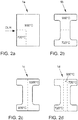
- Fig. 2 shows a top view of a plurality of sheet metal plates 1 formed from sheet steel, which were heated with the heating system 100 and each have a temperature distribution comprising different temperature zones. The division of the temperature zones is with Illustrated with dashed lines.
- the sheet metal plates 1b, 1c and 1d according to 2b, 2c and 2d it is an example of molded boards for the production of B-pillars for a car motor vehicle body.
- the heated sheet metal plate 1a (according to Fig. 2a ) has two temperature zones or ranges.
- the first inductor 110 is used to achieve a homogeneous basic heating of the sheet metal plate 1a to 720 ° C., the first inductor 110 being operated as a longitudinal field inductor.
- the second inductor 120 With the help of the second inductor 120, the marked area is heated to 930 ° C., the second inductor 120 being moved outwards during the heating, so that, as shown, a corner area is excluded from the high temperature.
- the form plate 1b (according to FIG Fig. 2b ), the second inductor 120 being positioned such that only the left half of the board (or, as shown, the upper half of the board) of the molded board 1b is heated up. If the temperature in the temperature zones should not be 720 ° C and 930 ° C, but, for example, 800 ° C and 1000 ° C, the first inductor 110 would be operated as a cross-field inductor in order to generate the higher basic heating.
- the form board 1c (according to Fig. 2c ) is heated homogeneously to 800 ° C. with the aid of the first inductor 110, for which purpose the first inductor 110 is operated as a cross-field inductor.
- the second inductor 120 With the help of the second inductor 120, only the front half of the board (or, as shown, the right half of the board) of the molded board 1c is heated up to 1000 ° C., for which purpose the second inductor 120 is energized only up to half the throughput of the board.
- the mold board 1d (according to Fig. 2d ) is heated homogeneously to 720 ° C. with the aid of the first inductor 110, for which purpose the first inductor 110 is operated as a longitudinal field inductor.
- the aid of the second inductor 120 only the middle band-like circuit board area of the molded board 1d is heated up to 930 ° C., for which purpose the second inductor 120 is only briefly energized when passing through the circuit board area in question.
- the related to the Fig. 2 Procedures explained by way of example can be combined to generate other temperature distributions or temperature profiles.
- the heating temperature can be influenced and, in particular, adjusted or set, which can also be done in a control loop.
- Fig. 3 shows the coil arrangement 115 of the first inductor 110, which comprises an upper inductor part 115a, with a conductor package 116a comprising a plurality of individual conductors, and a symmetrically formed lower inductor part 115b, with a conductor package 116b comprising a plurality of individual conductors.
- the coil arrangement 115 of the first inductor 110 is operated as a cross-field inductor, the metal plate 1 located between the inductor parts 115a and 115b being penetrated vertically by the magnetic field or the main magnetic flux, as illustrated by the magnetic flux lines B shown.
- the same coil arrangement 115 is operated as a longitudinal field inductor, the sheet metal plate 1 to be heated being penetrated by the magnetic field parallel to its surfaces, and the main magnetic flux lying virtually in the sheet metal plane, as illustrated by the magnetic flux lines B ′ shown.
- the magnetic field image does not differ from a classic longitudinal field, although the coil arrangement does not correspond to the conventional surrounding or encompassing structure, but has two inductor parts or an upper inductor 115a and a lower inductor 115b arranged above and below the sheet metal plate 1 to be heated.
- the first inductor 110 or its coil arrangement 115 can, analogously to the second inductor 120 or its coil arrangement 125, be designed to be movable or horizontally displaceable, in particular in such a way that the upper inductor part 115a and the lower inductor part 115b can be moved or moved together or synchronously are.
- the second inductor 120 can be configured analogously to the first inductor 110.
Landscapes
- Chemical & Material Sciences (AREA)
- Physics & Mathematics (AREA)
- Engineering & Computer Science (AREA)
- Thermal Sciences (AREA)
- Crystallography & Structural Chemistry (AREA)
- Mechanical Engineering (AREA)
- Materials Engineering (AREA)
- Metallurgy (AREA)
- Organic Chemistry (AREA)
- Electromagnetism (AREA)
- General Induction Heating (AREA)
- Shaping Metal By Deep-Drawing, Or The Like (AREA)
Claims (7)
- Procédé de chauffage en série de plaques de tôle d'acier (1) et en particulier de plaques de moulage dans une installation à passage continu, les plaques de tôle d'acier (1) comprenant, après le chauffage, une distribution de température comprenant différentes zones de température pour un formage à chaud ultérieur et en particulier pour un trempage sous presse,
caractérisé en ce que
les plaques de tôle d'acier (1), pour le chauffage, sont déplacées par rapport à au moins un premier inducteur (110), lequel fonctionne comme inducteur à champ longitudinal, puis lesdites plaques de tôle d'acier sont déplacées par rapport à au moins un deuxième inducteur (120), lequel fonctionne comme inducteur à champ transversal, la génération d'une distribution de température déterminée comprenant différentes zones de température étant effectuée en raison de l'agencement des deux inducteurs (110, 120) l'un par rapport à l'autre et/ou au moyen d'un mode de fonctionnement adapté des inducteurs (110, 120), de telle sorte que les plaques de tôle d'acier (1) sont chauffées, au niveau du premier inducteur (110), de manière homogène à une température allant jusqu'à 770 °C, puis un chauffage par zones à une température supérieure à 770 °C a lieu au niveau du deuxième inducteur (120). - Procédé selon la revendication 1,
caractérisé en ce que
le deuxième inducteur (120), lors du chauffage d'une plaque de tôle d'acier (1), n'est alimenté en courant que temporairement afin de chauffer uniquement une zone déterminée de la plaque de tôle d'acier (1). - Procédé selon la revendication 1 ou 2,
caractérisé en ce que
le deuxième inducteur (120), avant ou lors du chauffage d'une plaque de tôle d'acier (1), est déplacé afin de chauffer de manière ciblée uniquement une zone déterminée de la plaque de tôle d'acier (1). - Procédé selon l'une quelconque des revendications précédentes,
caractérisé en ce que
les plaques de tôle d'acier (1), entre le chauffage au niveau du premier inducteur (110) et celui au niveau du deuxième inducteur (120) ou après le chauffage au niveau du deuxième inducteur (120), sont traitées thermiquement dans un four (130), en particulier pour former ainsi une couche de protection contre la diffusion sur les plaques de tôle d'acier (1). - Installation de chauffage (100) pour le chauffage en série de plaques de tôle d'acier (1) et en particulier de plaques de moulage, les plaques de tôle d'acier (1) comprenant, après le chauffage, une distribution de température comprenant différentes zones de température pour un formage à chaud ultérieur et en particulier pour un trempage sous presse, comprenant :- au moins un premier inducteur (110), lequel est un inducteur à champ longitudinal ; et- au moins un deuxième inducteur (120), lequel est un inducteur à champ transversal ;ladite installation de chauffage (100) étant conçue sous la forme d'une installation à passage continu et les inducteurs (110, 120) étant disposés l'un derrière l'autre dans le sens de passage continu (DLR) des plaques de tôles d'acier (1) à chauffer et
le deuxième inducteur (120) comprenant une paire d'inducteurs à champ transversal comportant deux inducteurs à champ transversal situés l'un derrière l'autre dans le sens de passage continu (DLR), lesquels chevauchent les plaques de tôle d'acier (1) à chauffer à partir de côtés extérieurs opposés. - Installation de chauffage (100) selon la revendication 5,
caractérisé en ce que
le deuxième inducteur (120) est conçu pour être adaptable et/ou mobile, en particulier transversalement à un sens de passage continu (DLR). - Installation de chauffage (100) selon l'une quelconque des revendications 5 ou 6,
comprenant
un four (130) disposé entre le premier inducteur (110) et le deuxième inducteur (120) ou après le deuxième inducteur (120).
Applications Claiming Priority (1)
| Application Number | Priority Date | Filing Date | Title |
|---|---|---|---|
| DE102014211241.9A DE102014211241A1 (de) | 2014-06-12 | 2014-06-12 | Verfahren und Erwärmungsanlage für das serienmäßige Erwärmen von Blechplatinen mit Ausbildung unterschiedlicher Temperaturzonen |
Publications (2)
| Publication Number | Publication Date |
|---|---|
| EP2955239A1 EP2955239A1 (fr) | 2015-12-16 |
| EP2955239B1 true EP2955239B1 (fr) | 2020-03-11 |
Family
ID=53433015
Family Applications (1)
| Application Number | Title | Priority Date | Filing Date |
|---|---|---|---|
| EP15171386.4A Active EP2955239B1 (fr) | 2014-06-12 | 2015-06-10 | Procede et installation de chauffage pour le chauffage en serie de platines en tole par formation de differentes zones de temperature |
Country Status (3)
| Country | Link |
|---|---|
| EP (1) | EP2955239B1 (fr) |
| CN (1) | CN105296730B (fr) |
| DE (1) | DE102014211241A1 (fr) |
Families Citing this family (7)
| Publication number | Priority date | Publication date | Assignee | Title |
|---|---|---|---|---|
| DE102016219579A1 (de) * | 2016-10-10 | 2018-04-12 | Volkswagen Aktiengesellschaft | Verfahren zur Wärmebehandlung und Einrichtung zur Wärmebehandlung |
| SE540333C2 (sv) * | 2017-01-11 | 2018-07-03 | Tc Tech Sweden Ab Publ | Method and arrangement for metal hardening |
| KR101858611B1 (ko) * | 2017-04-12 | 2018-05-17 | 주식회사 새한산업 | 자동차용 도어 임팩트 빔 제조장치 |
| DE102018206343A1 (de) * | 2018-04-25 | 2019-10-31 | Volkswagen Aktiengesellschaft | Verfahren und Anlage zur Serienfertigung warmumgeformter Blechformteile aus einem Stahlblechband |
| US20210237138A1 (en) * | 2018-05-11 | 2021-08-05 | Magna International Inc. | Conduction pre-heating of sheet for hot forming |
| CN113578982B (zh) * | 2021-06-30 | 2023-08-15 | 首钢京唐钢铁联合有限责任公司 | 一种板坯感应加热调整方法及感应加热系统 |
| CN114713724B (zh) * | 2022-06-09 | 2022-08-30 | 北京科技大学 | 一种汽车桥壳用高强钢中厚板坯的加热装备及冲压工艺 |
Citations (2)
| Publication number | Priority date | Publication date | Assignee | Title |
|---|---|---|---|---|
| DE102008062270A1 (de) * | 2008-12-15 | 2010-06-17 | GM Global Technology Operations, Inc., Detroit | Vorrichtung und Verfahren zum Härten metallischer werkstücke |
| DE102009016027A1 (de) * | 2009-04-02 | 2010-10-07 | Volkswagen Ag | Verfahren zur Herstellung eines Bauteils, insbesondere eines Karosserieteiles, sowie Fertigungsstraße zur Durchführung des Verfahrens |
Family Cites Families (12)
| Publication number | Priority date | Publication date | Assignee | Title |
|---|---|---|---|---|
| DE20014361U1 (de) | 2000-08-19 | 2000-10-12 | Benteler Werke Ag | B-Säule für ein Kraftfahrzeug |
| DE10256621B3 (de) | 2002-12-03 | 2004-04-15 | Benteler Automobiltechnik Gmbh | Verfahren zur Herstellung eines Formbauteils mit mindestens zwei Gefügebereichen unterschiedlicher Duktilität und Durchlaufofen hierfür |
| DE10312623B4 (de) | 2003-03-19 | 2005-03-24 | Universität Hannover | Querfeld-Erwärmungsanlage |
| EP1643199B1 (fr) * | 2003-06-27 | 2010-05-05 | IHI Corporation | Four de traitement thermique sous vide de type a refroidissement par gaz et dispositif de changement de sens de gaz de refroidissement |
| JP5114671B2 (ja) * | 2007-04-16 | 2013-01-09 | 新日鐵住金株式会社 | 金属板の誘導加熱装置および誘導加熱方法 |
| CN101319271A (zh) * | 2008-07-18 | 2008-12-10 | 沈阳恒进真空科技有限公司 | 可对流加热的喷嘴冷却真空气淬炉 |
| DE102009015013B4 (de) | 2009-03-26 | 2011-05-12 | Voestalpine Automotive Gmbh | Verfahren zum Herstellen partiell gehärteter Stahlbauteile |
| DE102009019496A1 (de) * | 2009-05-04 | 2010-11-18 | Braun, Elisabeth | Vorrichtung und Verfahren zur Erwärmung warm umzuformender Werkstücke |
| DE102009042026A1 (de) * | 2009-09-17 | 2011-03-24 | Volkswagen Ag | Verfahren zum Vorbehandeln und Bereitstellen eines Blechteils |
| DE102012001742A1 (de) * | 2012-01-28 | 2013-08-01 | Volkswagen Aktiengesellschaft | Vorrichtung zum Erwärmen von Blechwerkstücken für ein nachfolgendes Warmumformen und insbesondere Presshärten |
| KR101376412B1 (ko) * | 2012-05-17 | 2014-03-20 | 현대하이스코 주식회사 | 핫스탬핑 블랭크 국부 가열 장치 및 이를 이용한 핫스탬핑 블랭크 가열방법 |
| EP2679692A1 (fr) * | 2012-06-29 | 2014-01-01 | GEDIA Gebrüder Dingerkus GmbH | Procédé de fabrication d'un composant de formage en tôle d'acier durci par une presse |
-
2014
- 2014-06-12 DE DE102014211241.9A patent/DE102014211241A1/de not_active Withdrawn
-
2015
- 2015-06-10 EP EP15171386.4A patent/EP2955239B1/fr active Active
- 2015-06-12 CN CN201510321676.5A patent/CN105296730B/zh active Active
Patent Citations (2)
| Publication number | Priority date | Publication date | Assignee | Title |
|---|---|---|---|---|
| DE102008062270A1 (de) * | 2008-12-15 | 2010-06-17 | GM Global Technology Operations, Inc., Detroit | Vorrichtung und Verfahren zum Härten metallischer werkstücke |
| DE102009016027A1 (de) * | 2009-04-02 | 2010-10-07 | Volkswagen Ag | Verfahren zur Herstellung eines Bauteils, insbesondere eines Karosserieteiles, sowie Fertigungsstraße zur Durchführung des Verfahrens |
Also Published As
| Publication number | Publication date |
|---|---|
| CN105296730A (zh) | 2016-02-03 |
| DE102014211241A1 (de) | 2015-12-17 |
| CN105296730B (zh) | 2018-05-04 |
| EP2955239A1 (fr) | 2015-12-16 |
Similar Documents
| Publication | Publication Date | Title |
|---|---|---|
| EP2955239B1 (fr) | Procede et installation de chauffage pour le chauffage en serie de platines en tole par formation de differentes zones de temperature | |
| EP2497840B1 (fr) | Système de four et procédé pour le réchauffage partiel d'ébauches métalliques | |
| DE102014101539B9 (de) | Warmformlinie und Verfahren zur Herstellung von warmumgeformten Blechprodukten | |
| EP2905346B1 (fr) | Procede de traitement de la chaleur | |
| DE102007043154A1 (de) | Verfahren und Vorrichtung zum Härten von Profilen | |
| DE102011078075A1 (de) | Durch Warmbehandlungsnachbearbeitung passendgemachte Eigenschaften | |
| EP2516079B1 (fr) | Procédé de laminage à chaud d'une brame et laminoir à chaud | |
| WO2010127837A2 (fr) | Dispositif et procédé pour chauffer des pièces à usiner façonnables à chaud | |
| EP2883967B1 (fr) | Procédé et dispositif de post-traitement d'un élément de formage métallique durci au moyen du chauffage par résistance électrique | |
| AT522345B1 (de) | Heizungsvorrichtung zum induktiven Erhitzen eines Flachstahlstreifens in einem Warmwalzwerk | |
| DE102015112293A1 (de) | Verfahren und Vorrichtung zur planheitsadaptiven Temperaturänderung von Metallbändern | |
| DE102011102167A1 (de) | Verfahren zur Herstellung eines Formbauteils mit mindestens zwei Gefügebereichen unterschiedlicher Duktilität und Erwärmungseinrichtung | |
| EP3353330A1 (fr) | Procédé de fabrication d'une matière brute pour la fabrication de composants métalliques présentant des zones de différentes résistances | |
| EP2540405B1 (fr) | Procédé de fabrication de platines de différentes épaisseurs | |
| DE10323796B3 (de) | Vorrichtung zum Erwärmen eines Metallbandes sowie mit einer derartigen Vorrichtung ausgestattete Anlagen zum Erzeugen von warmgewalztem Metallband | |
| EP2336374A1 (fr) | Procédé et dispositif destinés au chauffage et au refroidissement partiel de pièces usinées dans un four à passage continu | |
| WO2018103841A1 (fr) | Dispositif de thermorégulation pour thermoréguler un élément structural | |
| EP3420111B1 (fr) | Procédé de traitement thermique ciblé sur les zones d'une pièce | |
| WO2019101486A1 (fr) | Barre de refroidissement et processus de refroidissement avec taux de refroidissement variable pour tôles d'acier | |
| DE3032222A1 (de) | Vorrichtung zur kontinuierlichen herstellung stumpfnahtgeschweisster rohre | |
| EP3184655A1 (fr) | Four à traitement thermique et procédé de traitement thermique d'une plaque de tôle d'acier et procédé de production d'un composant de véhicule | |
| EP3201369B1 (fr) | Procédé de formation d'acier en bande ayant différentes propriétés mécaniques sur la largeur d'une bande | |
| CH711031B1 (de) | Verfahren zur Herstellung von Führungsschienen für ein Linearwälzlager. | |
| DE102017202377A1 (de) | Verfahren zur Wärmebehandlung, Verfahren zur Warmumformung, Vorrichtung zur Durchführung des Verfahrens und Kraftfahrzeug | |
| EP3985133A2 (fr) | Procédé de fabrication d'une platine d'acier, ainsi que station de thermorégulation |
Legal Events
| Date | Code | Title | Description |
|---|---|---|---|
| PUAI | Public reference made under article 153(3) epc to a published international application that has entered the european phase |
Free format text: ORIGINAL CODE: 0009012 |
|
| AK | Designated contracting states |
Kind code of ref document: A1 Designated state(s): AL AT BE BG CH CY CZ DE DK EE ES FI FR GB GR HR HU IE IS IT LI LT LU LV MC MK MT NL NO PL PT RO RS SE SI SK SM TR |
|
| AX | Request for extension of the european patent |
Extension state: BA ME |
|
| 17P | Request for examination filed |
Effective date: 20160616 |
|
| RBV | Designated contracting states (corrected) |
Designated state(s): AL AT BE BG CH CY CZ DE DK EE ES FI FR GB GR HR HU IE IS IT LI LT LU LV MC MK MT NL NO PL PT RO RS SE SI SK SM TR |
|
| STAA | Information on the status of an ep patent application or granted ep patent |
Free format text: STATUS: EXAMINATION IS IN PROGRESS |
|
| 17Q | First examination report despatched |
Effective date: 20171218 |
|
| RIC1 | Information provided on ipc code assigned before grant |
Ipc: C21D 1/42 20060101ALI20190802BHEP Ipc: F27D 99/00 20100101ALI20190802BHEP Ipc: C21D 9/60 20060101AFI20190802BHEP Ipc: C21D 1/673 20060101ALI20190802BHEP Ipc: H05B 6/10 20060101ALI20190802BHEP Ipc: H05B 6/44 20060101ALI20190802BHEP Ipc: H05B 6/40 20060101ALI20190802BHEP |
|
| GRAP | Despatch of communication of intention to grant a patent |
Free format text: ORIGINAL CODE: EPIDOSNIGR1 |
|
| STAA | Information on the status of an ep patent application or granted ep patent |
Free format text: STATUS: GRANT OF PATENT IS INTENDED |
|
| INTG | Intention to grant announced |
Effective date: 20190925 |
|
| GRAS | Grant fee paid |
Free format text: ORIGINAL CODE: EPIDOSNIGR3 |
|
| GRAA | (expected) grant |
Free format text: ORIGINAL CODE: 0009210 |
|
| STAA | Information on the status of an ep patent application or granted ep patent |
Free format text: STATUS: THE PATENT HAS BEEN GRANTED |
|
| AK | Designated contracting states |
Kind code of ref document: B1 Designated state(s): AL AT BE BG CH CY CZ DE DK EE ES FI FR GB GR HR HU IE IS IT LI LT LU LV MC MK MT NL NO PL PT RO RS SE SI SK SM TR |
|
| REG | Reference to a national code |
Ref country code: GB Ref legal event code: FG4D Free format text: NOT ENGLISH |
|
| REG | Reference to a national code |
Ref country code: CH Ref legal event code: EP |
|
| REG | Reference to a national code |
Ref country code: AT Ref legal event code: REF Ref document number: 1243205 Country of ref document: AT Kind code of ref document: T Effective date: 20200315 |
|
| REG | Reference to a national code |
Ref country code: IE Ref legal event code: FG4D Free format text: LANGUAGE OF EP DOCUMENT: GERMAN |
|
| REG | Reference to a national code |
Ref country code: DE Ref legal event code: R096 Ref document number: 502015011964 Country of ref document: DE |
|
| PG25 | Lapsed in a contracting state [announced via postgrant information from national office to epo] |
Ref country code: FI Free format text: LAPSE BECAUSE OF FAILURE TO SUBMIT A TRANSLATION OF THE DESCRIPTION OR TO PAY THE FEE WITHIN THE PRESCRIBED TIME-LIMIT Effective date: 20200311 Ref country code: NO Free format text: LAPSE BECAUSE OF FAILURE TO SUBMIT A TRANSLATION OF THE DESCRIPTION OR TO PAY THE FEE WITHIN THE PRESCRIBED TIME-LIMIT Effective date: 20200611 Ref country code: RS Free format text: LAPSE BECAUSE OF FAILURE TO SUBMIT A TRANSLATION OF THE DESCRIPTION OR TO PAY THE FEE WITHIN THE PRESCRIBED TIME-LIMIT Effective date: 20200311 |
|
| REG | Reference to a national code |
Ref country code: NL Ref legal event code: MP Effective date: 20200311 |
|
| PG25 | Lapsed in a contracting state [announced via postgrant information from national office to epo] |
Ref country code: GR Free format text: LAPSE BECAUSE OF FAILURE TO SUBMIT A TRANSLATION OF THE DESCRIPTION OR TO PAY THE FEE WITHIN THE PRESCRIBED TIME-LIMIT Effective date: 20200612 Ref country code: BG Free format text: LAPSE BECAUSE OF FAILURE TO SUBMIT A TRANSLATION OF THE DESCRIPTION OR TO PAY THE FEE WITHIN THE PRESCRIBED TIME-LIMIT Effective date: 20200611 Ref country code: LV Free format text: LAPSE BECAUSE OF FAILURE TO SUBMIT A TRANSLATION OF THE DESCRIPTION OR TO PAY THE FEE WITHIN THE PRESCRIBED TIME-LIMIT Effective date: 20200311 Ref country code: SE Free format text: LAPSE BECAUSE OF FAILURE TO SUBMIT A TRANSLATION OF THE DESCRIPTION OR TO PAY THE FEE WITHIN THE PRESCRIBED TIME-LIMIT Effective date: 20200311 Ref country code: HR Free format text: LAPSE BECAUSE OF FAILURE TO SUBMIT A TRANSLATION OF THE DESCRIPTION OR TO PAY THE FEE WITHIN THE PRESCRIBED TIME-LIMIT Effective date: 20200311 |
|
| REG | Reference to a national code |
Ref country code: LT Ref legal event code: MG4D |
|
| PG25 | Lapsed in a contracting state [announced via postgrant information from national office to epo] |
Ref country code: NL Free format text: LAPSE BECAUSE OF FAILURE TO SUBMIT A TRANSLATION OF THE DESCRIPTION OR TO PAY THE FEE WITHIN THE PRESCRIBED TIME-LIMIT Effective date: 20200311 |
|
| PG25 | Lapsed in a contracting state [announced via postgrant information from national office to epo] |
Ref country code: LT Free format text: LAPSE BECAUSE OF FAILURE TO SUBMIT A TRANSLATION OF THE DESCRIPTION OR TO PAY THE FEE WITHIN THE PRESCRIBED TIME-LIMIT Effective date: 20200311 Ref country code: IS Free format text: LAPSE BECAUSE OF FAILURE TO SUBMIT A TRANSLATION OF THE DESCRIPTION OR TO PAY THE FEE WITHIN THE PRESCRIBED TIME-LIMIT Effective date: 20200711 Ref country code: SK Free format text: LAPSE BECAUSE OF FAILURE TO SUBMIT A TRANSLATION OF THE DESCRIPTION OR TO PAY THE FEE WITHIN THE PRESCRIBED TIME-LIMIT Effective date: 20200311 Ref country code: PT Free format text: LAPSE BECAUSE OF FAILURE TO SUBMIT A TRANSLATION OF THE DESCRIPTION OR TO PAY THE FEE WITHIN THE PRESCRIBED TIME-LIMIT Effective date: 20200805 Ref country code: RO Free format text: LAPSE BECAUSE OF FAILURE TO SUBMIT A TRANSLATION OF THE DESCRIPTION OR TO PAY THE FEE WITHIN THE PRESCRIBED TIME-LIMIT Effective date: 20200311 Ref country code: CZ Free format text: LAPSE BECAUSE OF FAILURE TO SUBMIT A TRANSLATION OF THE DESCRIPTION OR TO PAY THE FEE WITHIN THE PRESCRIBED TIME-LIMIT Effective date: 20200311 Ref country code: EE Free format text: LAPSE BECAUSE OF FAILURE TO SUBMIT A TRANSLATION OF THE DESCRIPTION OR TO PAY THE FEE WITHIN THE PRESCRIBED TIME-LIMIT Effective date: 20200311 Ref country code: SM Free format text: LAPSE BECAUSE OF FAILURE TO SUBMIT A TRANSLATION OF THE DESCRIPTION OR TO PAY THE FEE WITHIN THE PRESCRIBED TIME-LIMIT Effective date: 20200311 |
|
| REG | Reference to a national code |
Ref country code: DE Ref legal event code: R097 Ref document number: 502015011964 Country of ref document: DE |
|
| PLBE | No opposition filed within time limit |
Free format text: ORIGINAL CODE: 0009261 |
|
| STAA | Information on the status of an ep patent application or granted ep patent |
Free format text: STATUS: NO OPPOSITION FILED WITHIN TIME LIMIT |
|
| PG25 | Lapsed in a contracting state [announced via postgrant information from national office to epo] |
Ref country code: IT Free format text: LAPSE BECAUSE OF FAILURE TO SUBMIT A TRANSLATION OF THE DESCRIPTION OR TO PAY THE FEE WITHIN THE PRESCRIBED TIME-LIMIT Effective date: 20200311 Ref country code: MC Free format text: LAPSE BECAUSE OF FAILURE TO SUBMIT A TRANSLATION OF THE DESCRIPTION OR TO PAY THE FEE WITHIN THE PRESCRIBED TIME-LIMIT Effective date: 20200311 Ref country code: ES Free format text: LAPSE BECAUSE OF FAILURE TO SUBMIT A TRANSLATION OF THE DESCRIPTION OR TO PAY THE FEE WITHIN THE PRESCRIBED TIME-LIMIT Effective date: 20200311 Ref country code: DK Free format text: LAPSE BECAUSE OF FAILURE TO SUBMIT A TRANSLATION OF THE DESCRIPTION OR TO PAY THE FEE WITHIN THE PRESCRIBED TIME-LIMIT Effective date: 20200311 |
|
| REG | Reference to a national code |
Ref country code: CH Ref legal event code: PL |
|
| 26N | No opposition filed |
Effective date: 20201214 |
|
| PG25 | Lapsed in a contracting state [announced via postgrant information from national office to epo] |
Ref country code: SI Free format text: LAPSE BECAUSE OF FAILURE TO SUBMIT A TRANSLATION OF THE DESCRIPTION OR TO PAY THE FEE WITHIN THE PRESCRIBED TIME-LIMIT Effective date: 20200311 Ref country code: PL Free format text: LAPSE BECAUSE OF FAILURE TO SUBMIT A TRANSLATION OF THE DESCRIPTION OR TO PAY THE FEE WITHIN THE PRESCRIBED TIME-LIMIT Effective date: 20200311 |
|
| PG25 | Lapsed in a contracting state [announced via postgrant information from national office to epo] |
Ref country code: LU Free format text: LAPSE BECAUSE OF NON-PAYMENT OF DUE FEES Effective date: 20200610 |
|
| REG | Reference to a national code |
Ref country code: BE Ref legal event code: MM Effective date: 20200630 |
|
| PG25 | Lapsed in a contracting state [announced via postgrant information from national office to epo] |
Ref country code: LI Free format text: LAPSE BECAUSE OF NON-PAYMENT OF DUE FEES Effective date: 20200630 Ref country code: CH Free format text: LAPSE BECAUSE OF NON-PAYMENT OF DUE FEES Effective date: 20200630 Ref country code: IE Free format text: LAPSE BECAUSE OF NON-PAYMENT OF DUE FEES Effective date: 20200610 |
|
| PG25 | Lapsed in a contracting state [announced via postgrant information from national office to epo] |
Ref country code: BE Free format text: LAPSE BECAUSE OF NON-PAYMENT OF DUE FEES Effective date: 20200630 |
|
| REG | Reference to a national code |
Ref country code: AT Ref legal event code: MM01 Ref document number: 1243205 Country of ref document: AT Kind code of ref document: T Effective date: 20200610 |
|
| PG25 | Lapsed in a contracting state [announced via postgrant information from national office to epo] |
Ref country code: AT Free format text: LAPSE BECAUSE OF NON-PAYMENT OF DUE FEES Effective date: 20200610 |
|
| PG25 | Lapsed in a contracting state [announced via postgrant information from national office to epo] |
Ref country code: TR Free format text: LAPSE BECAUSE OF FAILURE TO SUBMIT A TRANSLATION OF THE DESCRIPTION OR TO PAY THE FEE WITHIN THE PRESCRIBED TIME-LIMIT Effective date: 20200311 Ref country code: MT Free format text: LAPSE BECAUSE OF FAILURE TO SUBMIT A TRANSLATION OF THE DESCRIPTION OR TO PAY THE FEE WITHIN THE PRESCRIBED TIME-LIMIT Effective date: 20200311 Ref country code: CY Free format text: LAPSE BECAUSE OF FAILURE TO SUBMIT A TRANSLATION OF THE DESCRIPTION OR TO PAY THE FEE WITHIN THE PRESCRIBED TIME-LIMIT Effective date: 20200311 |
|
| PG25 | Lapsed in a contracting state [announced via postgrant information from national office to epo] |
Ref country code: MK Free format text: LAPSE BECAUSE OF FAILURE TO SUBMIT A TRANSLATION OF THE DESCRIPTION OR TO PAY THE FEE WITHIN THE PRESCRIBED TIME-LIMIT Effective date: 20200311 Ref country code: AL Free format text: LAPSE BECAUSE OF FAILURE TO SUBMIT A TRANSLATION OF THE DESCRIPTION OR TO PAY THE FEE WITHIN THE PRESCRIBED TIME-LIMIT Effective date: 20200311 |
|
| P01 | Opt-out of the competence of the unified patent court (upc) registered |
Effective date: 20230526 |
|
| PGFP | Annual fee paid to national office [announced via postgrant information from national office to epo] |
Ref country code: FR Payment date: 20230629 Year of fee payment: 9 Ref country code: DE Payment date: 20230620 Year of fee payment: 9 |
|
| PGFP | Annual fee paid to national office [announced via postgrant information from national office to epo] |
Ref country code: GB Payment date: 20230615 Year of fee payment: 9 |